

MIPRO ACT-717 User Manual
ACT-717B / ACT-727B / ACT-747B
2 CE 4 9 3 B
ACT-717 / ACT-727 / ACT-747
WIRELESS MICROPHONE SYSTEMS
User Guide
All rights reserved. Do not copy or forward without prior approvals MIPRO.
Specifications and design subject to change without notice. MN 014/02

! IMPORTANT SAFETY INSTRUCTIONS !
WARNING
1. Read these instructions.
2. Keep these instructions.
3. Heed all warnings.
4. Follow all instructions.
5. Do not use this apparatus near water.
6. Clean only with a dry cloth.
7. Do not block any ventilation openings. Install in accordance with the
manufacturer's instructions.
8. Do not install near any heat sources such as radiators, heat registers, stoves, or
other apparatus (including amplifiers) that produce heat.
9. Do not defeat the safety purpose of the polarised or ground plug: A polarised plug
has two blades with one wider than the other. The wide blade is provided for your
safety. When the provided plug does not fit into your outlet, consult an electrician
for replacement of the obsolete outlet.
10. Protect the power cord from being walked on or pinched particularly at plug,
convenience receptacles, and the point where they exit from the apparatus.
11. Only use attachments/accessories specified by the manufacturer.
12. Use only with a cart, stand, tripod, bracket, or table specified by the
manufacturer, or sold with the apparatus. When a cart is used, use
caution when moving the cart/apparatus combination to avoid
injury from tip-over.
13. Unplug this apparatus during lightning storms or when unused for
long periods of time.
14. Refer all servicing to qualified service personnel. Servicing is required when the
apparatus has been damaged in any way, such as power-supply cord or plug is
damaged, liquid has been spilled or objects have fallen into the apparatus, the
apparatus has been exposed to rain or moisture, does not operate normally, or has
been dropped.
15. To reduce the risk of fire or electric shock, do not expose this apparatus to rain or
moisture.
16. Apparatus should not be exposed to dripping or splashing and no objects filled with
liquids, should be placed on the apparatus.
17. Use only with the battery which specified by manufacturer.
18. The power supply cord set is to be the main disconnected device.
1. FOR OUTDOOR USE:
To reduce the risk of fire or electric shock, do not expose this apparatus to rain or
moisture.
2. UNDER WET LOCATION:
Apparatus should not be exposed to dripping or splashing and no objects filled with
liquids, such as vases should be placed on the apparatus.
3. SERVICE INSTRUCTIONS:
CAUTION - These servicing instructions are for use by qualified service personnel
only. To reduce the risk of electric shock, do not perform any servicing other than
that contained in the operating instructions unless you are qualified to do so.
This symbol indicates that dangerous voltage constituting a risk of electric
shock is present within this unit.
This symbol indicates that there are important operating and maintenance
instructions in the literature accompanying this unit.
& IC - ID
THIS DEVICE COMPLIES WITH PART15 OF THE FCC RULES AND RSS-123 ISSUE2 OF
CANADA. OPERATION IS SUBJECT TO THE FOLLOWING TWO CONDITIONS:
(1) This device may not cause interference.
(2) This device must accept any interference, including interference that may cause
undesired operation of the device. This equipment complies with FCC RF radiation
exposure limits set forth for an uncontrolled environment.
Disposal
200 5-08- 13
Dispose of any unusable devices or batteries responsibly and in
accordance with any applicable regulations.
Disposing of used batteries with domestic waste is to be avoided!
Batteries / NiCad cells often contain heavy metals such as cadmium(Cd),
mercury(Hg) and lead(Pb) that makes them unsuitable for disposal with
domestic waste. You may return spent batteries/ accumulators free of
charge to recycling centres or anywhere else batteries/accumulators are
sold.
By doing so, you contribute to the conservation of our environment!
Contents
True Diversity Receivers
TRUE DIVERSITY RECEIVERS
2 MIPRO'S Proprietary “ACT" Function & Operation
3
6
7
8
11
22
23
24
Part Names and Functions
Receiver Installation
Receiver Operation Tips
Rackmount Installation for Receivers
Receiver VFD Interface
Computer Network Interface Operation
General Tips for Improving System Performance
Troubleshooting
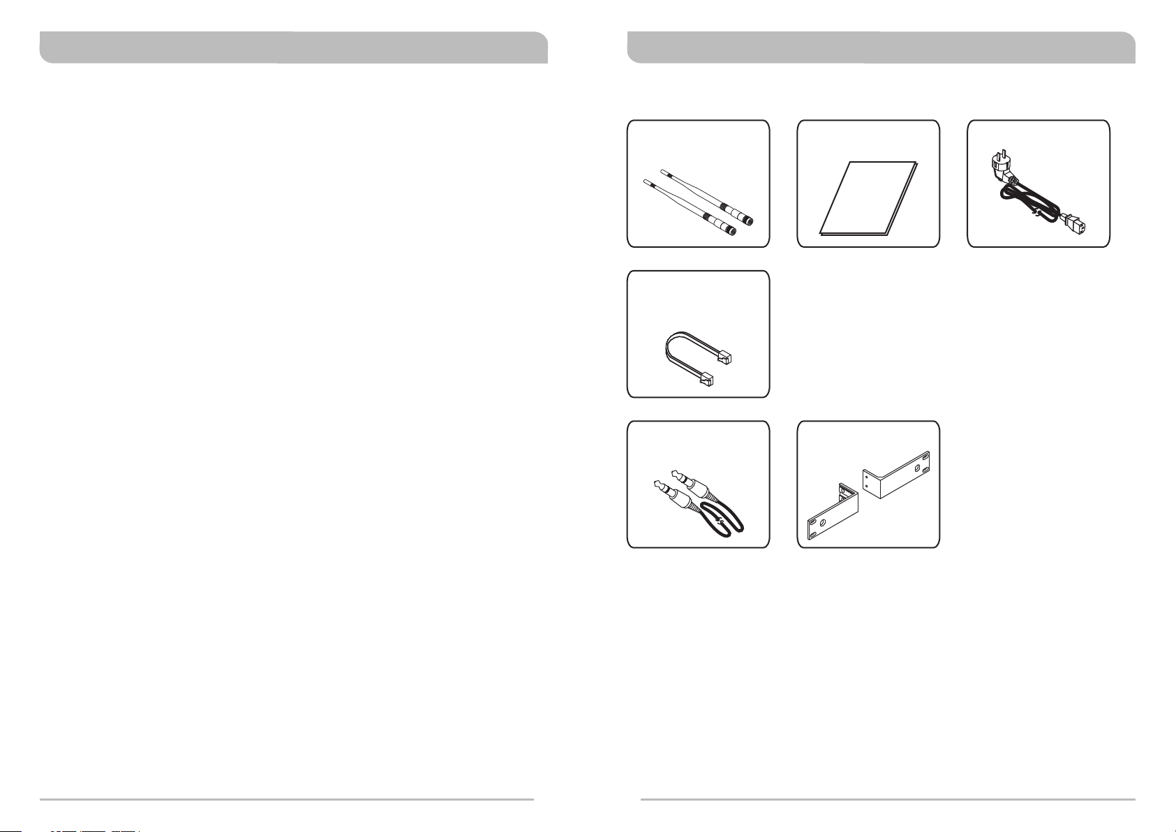
Included Accessories
Antenna × 2 User Guide × 1
Phone Cable × 1
Audio Output Cable × 1
(ACT-717/ACT-717B)
Rack-mount kit × 1 set
(ACT-717/ACT-717B)
Power cable × 1
0
1
True Diversity ReceiversTrue Diversity Receivers
CHANNEL
1
ACT SET
BA
BA
L
SQ
GRP
CH
NAME
ADD
FRQ
SET
MIPRO'S PROPRIETARY "ACT" FUNCTION & OPERATION
What is ACT?
“ACT” stands for “Automatic Channel Targeting”. MIPRO was the first manufacturer in
the industry to use infrared (IR) technology to automatically synchronize the frequency
selected on the receiver to any ACT handheld or bodypack transmitter on the same
frequency band.
ACT Features
!
No manual frequency adjusting needed, unlike traditional transmitters.
Simple, fast and precise frequency set-up without mechanical errors.
!
Once the frequency has been set, the data is stored in memory, meaning that the
!
frequency is set until it is changed by performing the “ACT” function again, even
after powering off.
ACT Set-Up
! Ensure a receiver channel is set up.
! Press and release the “ACT” button to activate the ACT function. Once activated,
the word “ACT” appears.
! Locate the transmitter infrared (IR) port and bring it within 30cm (12”) of the
receiver's ACT port. The receiver's IR port is a round “window” located between the
ACT & SET buttons. The transmitter IR port is normally indicated by a round red
colored spot.
! When the frequencies are synchronized successfully between the transmitter and
receiver, the word “ACT” disappears and the original group and channel reappears.
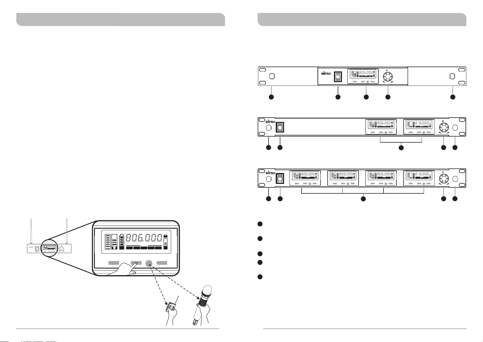
PART NAMES AND FUNCTIONS
Front Panel:
ACT-717 / ACT-717B Single-Channel True-Diversity Receiver
ON
POWER
SET
BA
BA
FRQ
GRPCHNAME
CHANNEL1ACT SET
ADD
1 2 3 4 5
ACT-727 / ACT-727B Dual-Channel True-Diversity Receiver
ON
POWER
CHANNEL1ACT SET
1 2 4 5
ACT-747 / ACT-747B Four-Channel True-Diversity Receiver
POWER
ON
BA
CHANNEL1ACT SET
BA
GRPCHNAME
L
SET
SQ
FRQ
ADD
BA
CHANNEL2ACT SET
1 2 4
BA
GRPCHNAME
L
SET
SQ
FRQ
ADD
CHANNEL3ACT SET
3
SET
L
SQ
SELECT
L
SET
BA
BA
SQ
FRQ
GRPCHNAME
ADD
SET
BA
BA
FRQ
GRPCHNAME
CHANNEL2ACT SET
SQ
ADD
3
L
SET
BA
BA
SQ
FRQ
GRPCHNAME
ADD
SET
BA
BA
FRQ
GRPCHNAME
CHANNEL4ACT SET
SQ
ADD
SET
SELECT
SET
SELECT
5
ON
POWER
BA
BA
CHANNEL1ACT SET
GRPCHNAME
1
Antenna “A” Front Mount: Allows an optional FBC-71 rear-to-front antenna
cable for front antenna placement.
2
SET
L
SET
SQ
FRQ
ADD
ACT-71 7
SELECT
Power Switch and Indicator: When the switch is turned on, the red indicator
illuminates to denote normal power status.
3
Receiver Display: Color VFDs.
4
Rotary Controller: To set up parameters. Move cursors by turning the control
clockwise or counterclockwise.
5
Antenna “B” Front Mount: Allows an optional FBC-71 rear-to-front antenna
cable for front antenna placement.
<
30
c
m
(12
in
.)
or
2
3
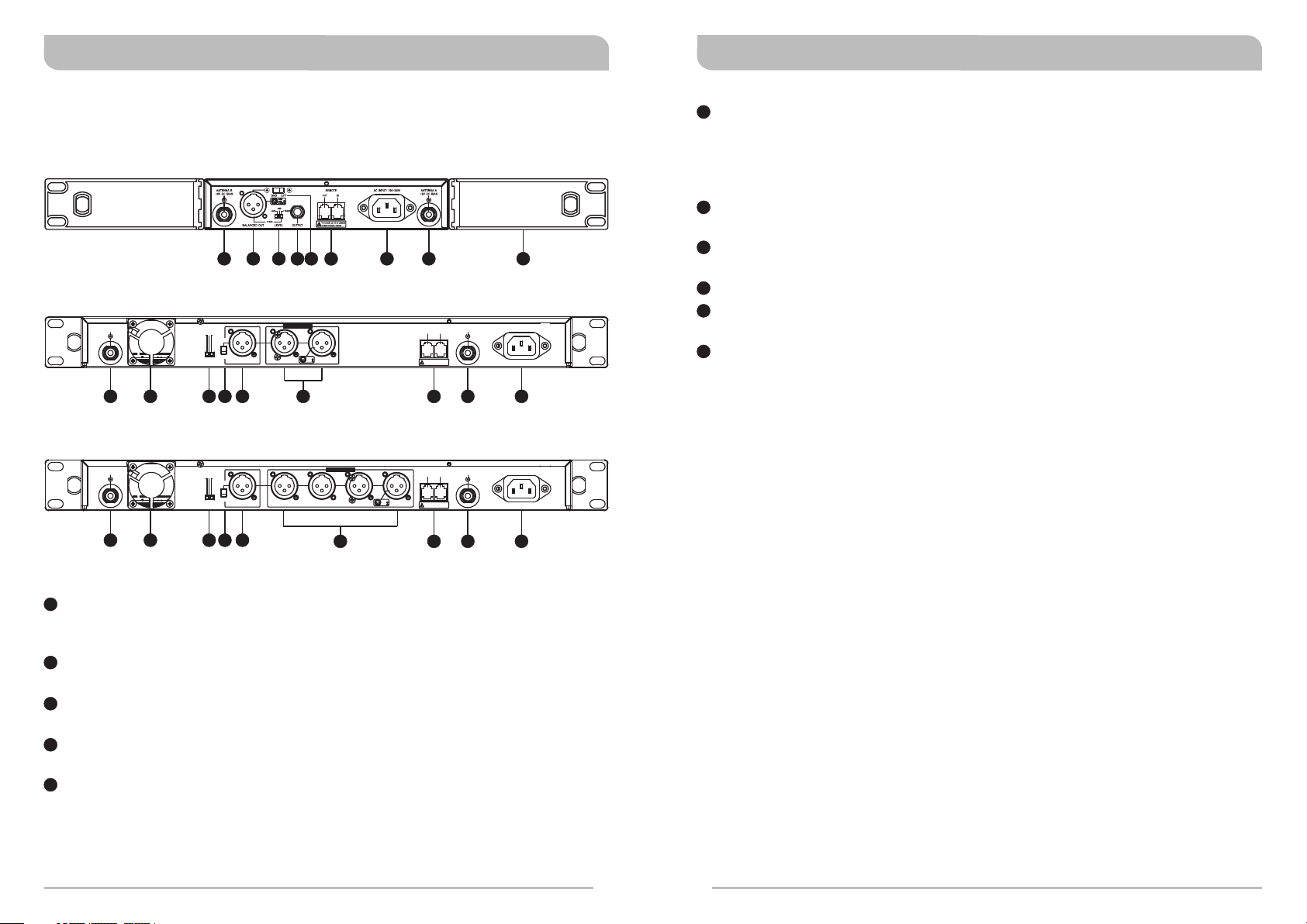
Rear Panel:
ACT-717 / ACT-717B Single-Channel True-Diversity Receiver
10
6
8 11
16
12
ACT-727 / ACT-727B Dual-Channel True-Diversity Receiver
ANTENNA B
+8V DC BIAS
0dB
-6dB
+16dB
LIFT
GND
LEVEL
BALANCED OUT
1: GND
21
+
2: HOT
3
-
3: COLD
CH 1CH 2MIXED
14 13
OUT
This connector can not be connected
to telecommunication networks.
True Diversity ReceiversTrue Diversity Receivers
11
Unbalanced Audio Output Jack: ¼” PHONE PLUG type connector provides
unbalanced audio output signal from this jack to the mixer (ACT-717/ACT-717B
only). Output level is selectable from among 3 levels: “-6dB”, “0dB” and +10dB
(the switch will show +16dB on the receiver, but actually puts out +10dB on the
unbalanced jack).
12
Network Interface Connector: For linking the receivers to a computer system-
monitoring program.
13
15
ANTENNA A
REMOTE
+8V DC BIAS
IN
AC INPUT: 100~240V
Rear Antenna “A” Input Connector: The A antenna can be installed directly to
this antenna connector which also provides power to an optional antenna booster.
14
AC Power Socket: The input socket for AC power ranging from 100V ~ 240V AC.
15
Rack-Mount Brackets: To install the receiver into a standard EIA 19-inch rack
case.
16
LIFT/GND switch: Lifts ground from Pin 1 of the XLR connector. (GND= default).
7
6
9
16
8
10
12
13 14
ACT-747 / ACT-747B Four-Channel True-Diversity Receiver
ANTENNA B
+8V DC BIAS
6
7
6
Rear Antenna “B” Input Connector: The “B” antenna can be installed directly
0dB
-6dB
+16dB
LIFT
GND
LEVEL
8 9
16
BALANCED OUT
10
1: GND
21
+
2: HOT
3
-
CH 1CH 2CH 3CH 4MIXED
3: COLD
REMOTE
OUT
This connector can not be connected
to telecommunication networks.
12
ANTENNA A
+8V DC BIAS
IN
13 14
AC INPUT: 100~240V
to this antenna connector which also provides power to an optional antenna
booster.
7
Ventilation Fan: Ensures stable performance in long hours of operation under
high temperature environments.
8
Level Switch: "0dB" selection is for "Microphone level" output. “+16dB" selection
is for “AUX level” output. “-6dB” selection is for half of cable microphone volume.
9
Mixed AF Output Jack: A balanced output jack for mixed AF signals from all
installed channels; 3 output levels to choose from.
10
Balanced Audio Output Jack: XLR type connector provides balanced audio
output signal from this jack to the mixer, and output level is selectable from
among 3 levels: “-6dB”, “0dB” and “+16dB”.
4
5
 Loading...