

Page 1
Operating Instructions
To Purchase, Visit Avobus.com or call 1-800-674-3655
0070-01-0628-02_revD_Trio ops color.indd 1 3/10/10 5:37:08 PM
Page 2

Operating Instructions
Page 3

Trio™ is a U.S. trademark of Mindray DS USA, Inc.
Navigator
™
Masimo SET
®
Nellcor
and OxiMax® are U.S. registered trademarks of Nellcor Puritan Bennett Inc.
SatSeconds
is a U.S. trademark of Mindray DS USA, Inc.
®
is a U.S. registered trademark of Masimo Corp.
™
is a U.S. trademark of Nellcor Puritan Bennett Inc.
Copyright © Mindray DS USA, Inc., 2008. All rights reserved. Contents of this publication may not be
reproduced in any form without permission of Mindray DS USA, Inc.
0070-10-0666-01 Trio™ Operations Manual
Page 4

Table of Contents
Foreword....................................................................................................................................................... v
Warnings, Precautions And Notes ....................................................................................................................v
Warnings ......................................................................................................................................................vi
Precautions ....................................................................................................................................................vii
Notes............................................................................................................................................................xi
Indication For Use........................................................................................................................................... xi
Unpacking ..................................................................................................................................................... xi
Symbols.........................................................................................................................................................xii
General Product Description.............................................................................................. 1 - 1
Front Panel..................................................................................................................................................... 1 - 3
Front Panel Keypad ................................................................................................................................. 1 - 4
Display................................................................................................................................................... 1 - 6
Left Side Panel................................................................................................................................................ 1 - 10
Right Side Panel ............................................................................................................................................. 1 - 11
Rear Panel ..................................................................................................................................................... 1 - 12
Operations ....................................................................................................................... 2 - 1
Getting Started ............................................................................................................................................... 2 - 1
Setting-up Patients.................................................................................................................................... 2 - 1
Setting the Clock (Date and Time).............................................................................................................. 2 - 2
Menus ........................................................................................................................................................... 2 - 2
System Menu.................................................................................................................................................. 2 - 3
Patient Setup........................................................................................................................................... 2 - 3
List Trend................................................................................................................................................ 2 - 5
Graphic Trend ........................................................................................................................................ 2 - 5
Mark Event ............................................................................................................................................. 2 - 6
Monitor Setup ......................................................................................................................................... 2 - 6
Maintenance........................................................................................................................................... 2 - 13
Normal Screen........................................................................................................................................ 2 - 13
Parameter Menus............................................................................................................................................ 2 - 14
Electrocardiogram (ECG) Monitoring ......................................................................................................... 2 - 14
Respiration Monitoring............................................................................................................................. 2 - 29
Monitoring .................................................................................................................................... 2 - 32
SpO
2
NIBP Monitoring...................................................................................................................................... 2 - 44
Temperature Monitoring ........................................................................................................................... 2 - 53
IBP Monitoring (Optional)......................................................................................................................... 2 - 56
Alarms........................................................................................................................................................... 2 - 63
Alarm Categories .................................................................................................................................... 2 - 63
Alarm Priorities........................................................................................................................................ 2 - 64
Alarm Setup Menus ................................................................................................................................. 2 - 64
Alarm Troubleshooting ............................................................................................................................. 2 - 75
Trends ........................................................................................................................................................... 2 - 76
Graphic Trend ........................................................................................................................................ 2 - 76
List Trend................................................................................................................................................ 2 - 79
Recorder (Optional) ........................................................................................................................................ 2 - 82
Print Functions......................................................................................................................................... 2 - 82
Recorder Troubleshooting ......................................................................................................................... 2 - 86
Defaults............................................................................................................................ 3 - 1
Default Configurations..................................................................................................................................... 3 - 1
Factory Default Configuration.................................................................................................................... 3 - 1
User Default Configuration........................................................................................................................ 3 - 6
Current Configuration .............................................................................................................................. 3 - 6
Non-Volatile Configuration ....................................................................................................................... 3 - 7
Trio™ Operating Instructions 0070-10-0666-01 i
To Purchase, Visit Avobus.com or call 1-800-674-3655
Page 5

Table of Contents
User Maintenance............................................................................................................. 4 - 1
Introduction.................................................................................................................................................... 4 - 1
Decontamination of the Monitor........................................................................................................................ 4 - 2
Care and Cleaning of the Monitor .................................................................................................................... 4 - 2
Care and Cleaning of Accessories.................................................................................................................... 4 - 3
SpO
Sensors ......................................................................................................................................... 4 - 3
2
Blood Pressure Cuffs ................................................................................................................................ 4 - 4
Temperature Sensor Cleaning and Disinfection (Reusable).................................................................................... 4 - 6
Battery Replacement and Maintenance .............................................................................................................. 4 - 6
Recorder Maintenance .................................................................................................................................... 4 - 7
Recorder Paper Replacement .................................................................................................................... 4 - 8
Care and Storage of Thermal Paper.................................................................................................................. 4 - 9
Care and Cleaning of ECG Cables and Leadwires ............................................................................................. 4 - 9
Accessories ....................................................................................................................... 5 - 1
Optional Accessories ...................................................................................................................................... 5 - 1
NIBP Accessories..................................................................................................................................... 5 - 1
Oximetry Sensors and Accessories............................................................................................................. 5 - 3
Reusable Temperature Probes.................................................................................................................... 5 - 4
Disposable Temperature Probes................................................................................................................. 5 - 4
ECG Accessories..................................................................................................................................... 5 - 4
IBP Accessories ....................................................................................................................................... 5 - 5
Miscellaneous Accessories........................................................................................................................ 5 - 5
Mounting Kits and Accessories.................................................................................................................. 5 - 6
Replacement Parts, Trio Rolling Stand......................................................................................................... 5 - 6
Appendix ......................................................................................................................... 6 - 1
Specifications................................................................................................................................................. 6 - 1
Safety Standards ..................................................................................................................................... 6 - 1
Safety Designations ................................................................................................................................. 6 - 2
Performance / Accuracy .......................................................................................................................... 6 - 3
Environmental / EMC .............................................................................................................................. 6 - 4
United States Food and Drug Administration Documents............................................................................... 6 - 4
Patient Parameter Specifications ....................................................................................................................... 6 - 5
ECG ...................................................................................................................................................... 6 - 5
ECG Performance Requirements ................................................................................................................ 6 - 5
ANSI/AAMI EC13-2002 Compliance........................................................................................................ 6 - 7
ECG Systole Detector and Heart Rate Meter ............................................................................................... 6 - 8
ECG Respiration Performance Requirements................................................................................................ 6 - 9
NIBP Sub-System Performance Characteristics ............................................................................................. 6 - 9
IBP Parameter Sub-System Performance Characteristics................................................................................. 6 - 12
IBP Safety Requirements............................................................................................................................ 6 - 12
Temperature Parameter Performance Characteristics .................................................................................... 6 - 13
Performance Requirements............................................................................................................... 6 - 13
SpO
Physical Specifications..................................................................................................................................... 6 - 17
2
Information Display and Control................................................................................................................ 6 - 17
LED Indicators ......................................................................................................................................... 6 - 17
Real Time Clock ...................................................................................................................................... 6 - 18
Input/Output Communications................................................................................................................... 6 - 18
Power Supply.......................................................................................................................................... 6 - 19
AC Mains Power Source .......................................................................................................................... 6 - 19
Battery Power.......................................................................................................................................... 6 - 19
Data Storage .......................................................................................................................................... 6 - 20
Printers................................................................................................................................................... 6 - 21
Physical Characteristics ............................................................................................................................ 6 - 21
ii 0070-10-0666-01 Trio™ Operating Instructions
Page 6

Table of Contents
Environmental and Safety Characteristics.................................................................................................... 6 - 22
Warranty Statements....................................................................................................................................... 6 - 28
Phone Numbers and How To Get Assistance...................................................................................................... 6 - 29
Manufacturer’s Responsibility ........................................................................................................................... 6 - 29
Trio™ Operating Instructions 0070-10-0666-01 iii
Page 7

This page intentionally left blank.
iv 0070-10-0666-01 Trio™ Operating Instructions
To Purchase, Visit Avobus.com or call 1-800-674-3655
Page 8

Foreword Introduction
Foreword
The Trio Operating Instructions are intended to provide information for proper operation.
General knowledge of monitoring and an understanding of the features and the functions of
the Trio Monitor are prerequisites for proper use.
Do not operate this monitor before reading these instructions.
Information for servicing this instrument is contained in the Trio Monitor Service Manual,
(Part Number 0070-00-0627-03). For additional information or assistance, please contact a
service representative in your area.
CAUTION: U.S. Federal Law restricts this device to sale by or on the
order of a physician or other practitioner licensed by U.S.
state law to use or order the use of this device.
Patents: This device is covered under one (1) of more of the following U.S. patents and any
foreign equivalents 4,621,643; 4,700,708; 4,770,179; 4,869,254; 4,653,498;
4,928,692; 4,934,372; 4,960,126; 5,078,136; 5,482,036; 5,490,505; 5,632,272;
5,685,299; 5,743,263; 5,758,644; 5,769,785; 6,157,850; 6,206,830; 4,802,486;
5,351,685; 5,421,329; 5,485,847; 5,533,507; 5,577,500; 5,803,910; 5,853,364;
5,865,736; 6,035,223; 6,263,222; 6,298,252; 6,463,310; 6,591,123; 6,675,031;
6,708,049; 6,801,797; 6,083,172 Re. 35,122. Possession or purchase of this device does
not convey any express or implied license to use this device with replacement parts which
would, alone, or in combination with this device, fall within the scope or one (1) or more of
the patents related to this device.
Warnings, Precautions And Notes
Please read and adhere to all warnings, precautions and notes listed here and in the
appropriate areas throughout this manual.
A WARNING is provided to alert the user to potential serious outcomes (death, injury, or
serious adverse events) to the patient or the user.
A CAUTION is provided to alert the user to use special care necessary for the safe and
effective use of the device. They may include actions to be taken to avoid effects on patients
or users that may not be potentially life threatening or result in serious injury, but about which
the user should be aware. Cautions are also provided to alert the user to adverse effects on
this device of use or misuse and the care necessary to avoid such effects.
A NOTE is provided when additional general information is applicable.
Trio™ Operating Instructions 0070-10-0666-01 v
Page 9

Introduction Warni ngs
Warnings
WARNING: Equipment not suitable for use in the presence of a
flammable anesthetic mixture with air or with oxygen or
with nitrous oxide.
WARNING: The AC line cord and interface cables (i.e. non-patient
WARNING: Observe extreme caution when a defibrillator is used on a
WARNING: Route cables neatly. Ensure cables, hoses, and wires are
WARNING: This monitor is not intended for use in an MR environment.
WARNING: When using electrosurgery equipment, leads should be
WARNING: The Trio monitor is intended for hospital use under the direct
WARNING: Ensure that the conductive parts of ECG electrodes do not
WARNING: Pacemaker patients’ rate meters may continue to count the
cables) may utilize the same ground. Therefore, removal of
the AC line cord does not necessarily isolate the Trio, if nonpatient interface cables are attached.
patient. Do not touch any part of patient, table or monitor
when a defibrillator is in use.
away from patient’s neck to avoid strangulation. Keep
floors and walkways free of cables to reduce risk to
hospital personnel, patients and visitors.
placed equidistant from electrosurgery electrotome and the
grounding plate to avoid cautery. Ensure that wires from
electrosurgery equipment and ECG cables do not become
tangled.
supervision of a licensed health care practitioner.
contact other conductive parts, including earth ground.
pacemaker rate during occurrences of cardiac arrest or
some arrhythmias. Do not rely entirely upon rate meter
alarms. Keep pacemaker patients under close surveillance.
See Appendix section of this manual for disclosure of the
pacemaker pulse rejection capability of this instrument.
WARNING: Do not clean the monitor or sensors while it is on and/or
connected to AC power.
WARNING: Ensure that the ECG lead wires are neatly secured in a
manner that will prevent them from encircling the patient’s
neck, creating a strangulation hazard.
WARNING: Perform the decontamination process with the unit powered
down and power cord removed.
vi 0070-10-0666-01 Trio™ Operating Instructions
Page 10

Precautions Introduction
Precautions
CAUTION: The use of portable and mobile RF communications
equipment, in the proximity of the Trio, can affect the
performance of this monitor.
CAUTION: The use of unapproved accessories may diminish monitor
CAUTION: The Trio should not be used adjacent to or stacked with
CAUTION: Operation of the Trio below the minimum amplitude or
CAUTION: When using electrosurgery equipment, never place an
CAUTION: The patient size selection should be matched to the actual
CAUTION: To avoid possible damage to the Trio, use only approved
CAUTION: Line isolation transients may resemble actual cardiac
CAUTION: Use of accessories, transducers and cables other than those
performance.
other equipment. If adjacent or stacked use is necessary, the
Trio should be observed to verify normal operation in the
configuration in which it will be used.
value of PATIENT physiological signal may cause inaccurate
results (see section 6.0, Appendix).
electrode near the grounding plate of the electrosurgery
device. This may create interference with the ECG signal.
patient before monitoring begins.
ECG cables and approved accessories.
waveforms, thus inhibiting heart rate alarms. Check lead
wires for damage and ensure good skin contact prior to and
during use. Always use fresh electrodes and follow proper
skin preparation techniques.
specified in the manual may result in increased
Electromagnetic Emissions or decreased Electromagnetic
Immunity of the Trio. It can also cause delayed recovery
after the discharge of a cardiac defibrillator.
CAUTION: Thoracic respiration measurement may interfere with some
CAUTION: If a 3 Lead cable is used when a unit is set to 5 lead mode,
CAUTION: Do not place the SpO
CAUTION: Tissue damage or inaccurate measurement may be caused
CAUTION: Excessive ambient light may cause inaccurate
Trio™ Operating Instructions 0070-10-0666-01 vii
pacemakers. Refer to the pacemaker's manufacturer
supplied manual.
no ECG signal will be obtained. If a 5 lead cable is used
when the unit is set to 3 lead mode only Lead I, II and III are
operable.
invasive catheter or blood pressure cuff in place.
by incorrect sensor application or use, such as wrapping too
tightly, applying supplemental tape, failing to inspect the
sensor site periodically or failing to position appropriately.
Carefully read the sensor directions and all precautionary
information before use.
measurements. In such cases, cover the sensor site with
opaque material.
2
To Purchase, Visit Avobus.com or call 1-800-674-3655
sensor on an extremity with an
Page 11

Introduction Precautions
CAUTION: Inaccurate SpO
measurements may be caused by:
2
• incorrect sensor application or use
• significant levels of dysfunctional hemoglobins, (e.g.,
carboxyhemoglobin or methemoglobin)
• intra-vascular dyes such as indocyanine green or
methylene blue
• exposure to excessive illumination such as surgical
lamps (especially ones with a xenon light source),
bilirubin lamps, fluorescent lights, infrared heating
lamps, or excessive ambient light. In such cases, cover
the sensor site with opaque material.
• excessive patient movement
• venous pulsations
• electro-surgical interference
• placement of a sensor on an extremity that has a blood
pressure cuff, arterial catheter or intra-vascular line.
• nail polish or fungus
CAUTION: In certain situations in which perfusion and signal strength
are low, such as in patients with thick or pigmented skin,
inaccurately low SpO
oxygenation should be made, especially in preterm infants
readings will result. Verification of
2
and patients with chronic lung disease, before instituting
any therapy or intervention.
CAUTION: Many patients suffer from poor peripheral perfusion due to
hypothermia, hypovolemia, severe vasoconstriction,
reduced cardiac output, etc. These symptoms may cause a
loss in vital sign readings.
CAUTION: If the sensor or patient cable are damaged in any way,
discontinue use immediately. To prevent damage, do not
soak or immerse the sensor in any liquid solution. Do not
attempt to sterilize.
CAUTION: When equipped with Masimo SpO
oxygen sensors and cables. Use of other oxygen sensors
, use only Masimo
2
may cause improper oximeter performance.
CAUTION: When equipped with Nellcor SpO
sensors and cables. Use of other oxygen sensors may cause
, use only Nellcor oxygen
2
improper oximeter performance.
CAUTION: When using the Trio equipped with SpO
, use only
2
approved supplied oxygen transducers and Patient Cables.
Use of other oxygen transducers may cause improper
oximeter performance.
CAUTION: Use only approved blood pressure cuffs and hoses with the
Trio.
CAUTION: Please consult a physician for interpretation of blood
pressure measurements.
CAUTION: A blood pressure measurement can be affected by the
position of the patient, and his/her physiological condition
as well as other factors, such as patient movement.
viii 0070-10-0666-01 Trio™ Operating Instructions
Page 12

Precautions Introduction
CAUTION: A patient's skin is sometimes fragile (i.e. on pediatric and
CAUTION: Observe caution on all patients (Pediatrics and Adults) when
CAUTION: Any condition which may affect the regularity and strength
CAUTION: When cleaning sensors, do not use an excessive amount of
CAUTION: Do not subject the sensor to autoclaving.
geriatric patients or due to physiological conditions). In
these cases, a longer time duration between measurements
should be considered to decrease the number of cuff
inflations over a period of time. In extreme cases, a thin
layer of soft roll or cotton padding may be applied to the
limb in order to cushion the skin when the cuff is inflated.
This measure may affect NIBP performance and should be
used with caution.
NIBP is set to the Continuous mode and the 1 minute
Interval. When the NIBP “Continuous” interval is chosen, the
Trio will continually take back to back blood pressure
readings. As a safety precaution, a limit is placed on the
Continuous mode to revert to an interval of every 5 minutes
after 5 minutes of continuous readings.
of arterial pressures (such as patient movement, cardiac
arrhythmias, restriction of hose, etc.), will affect the
accuracy and ability to measure the NIBP.
liquid. Wipe the sensor surface with a soft cloth, dampened
with a cleaning solution.
CAUTION: Do not use sensors or cables that are damaged or have
deteriorated.
CAUTION: Replace the battery with one of the following part numbers:
0146-00-0043 (for a sealed lead acid battery),
0146-00-0069 (for a Lithium Ion battery).
CAUTION: Remove the battery if the Trio is not likely to be used for an
extended period of time.
CAUTION: Remove the battery prior to shipping the Trio.
CAUTION: To avoid permanent damage, do not expose metal
components (pins, sockets, snaps) to disinfectants, soaps or
chemicals.
CAUTION: The cuff must be properly applied to the patient's limb
before inflating. If it is inflated without being securely
wrapped, damage to the cuff can result.
CAUTION: Only connect NIBP Luer fittings to Blood Pressure Cuff or
CAUTION: During the decontamination process, do not get the LpH SE
CAUTION: To ensure continued use of the Factory Defaults when the
Monitor.
Germicidal detergent into any vent openings.
unit is powered off and on, save the Factory Defaults as the
User Default Configuration (see section 3.1.2).
Trio™ Operating Instructions 0070-10-0666-01 ix
Page 13

Introduction Precautions
CAUTION: Prolonged and continuous monitoring may increase the risk
of skin erosion and pressure necrosis at the site of the
sensor. Check the SpO
proper positioning, alignment and skin integrity at least
every eight (8) hours; with the Adult and Pediatric re-usable
finger sensor, check every four (4) hours; for patients of
poor perfusion or with skin sensitive to light, check every
2 - 3 hours; more frequent examinations may be required
for different patients. Change the sensor site if signs of
circulatory compromise occur.
sensor site frequently to ensure
2
x 0070-10-0666-01 Trio™ Operating Instructions
To Purchase, Visit Avobus.com or call 1-800-674-3655
Page 14

Notes Introduction
Notes
NOTE: Potential hazards due to errors in software or hardware
have been minimized by actions taken in accordance with
IEC 60601-1.
NOTE: Messages are provided to assist in the identification and
NOTE: Should the device become accidently saturated with any
NOTE: The comparison testing conducted via the auscultatory
NOTE: Only operate this device within the specified operating
correction of problems that may occur with the monitor.
liquid, immediately discontinue use and contact Customer
Service.
method used both Phase 4 and Phase 5 Korotkoff sounds.
Reports of study findings for both the auscultatory method
as well as the intra-arterial methods are available by
contacting Technical Support (201) 995-8116.
signal range.
Indication For Use
The Trio™ monitor is intended for use in healthcare settings under the direct supervision of a
licensed healthcare practitioner. The intended use of the monitor is to monitor physiologic
parameter data on adult and pediatric patients. Physiologic data includes:
electrocardiogram, invasive blood pressure, non-invasive blood pressure (NIBP), pulse
oximetry, heart rate (derived from ECG, SpO
summarized in the operating instructions manual. The information can be displayed, stored,
trended and printed.
The monitor is not intended for home use. The monitor is not intended to be an apnea
monitor. It was not designed or validated for use as an apnea monitor.
, or NIBP), respiration and temperature as
2
Unpacking
Remove the instrument and accessories from the shipping cartons and examine them for signs
of shipping damage. Save all packing materials, invoice and bill of lading. These may be
required to process a claim with the carrier. Check all materials against the packing list.
Contact your Sales Representative or Distributor for assistance in resolving shipping
problems.
Trio™ Operating Instructions 0070-10-0666-01 xi
Page 15
Introduction Symbols
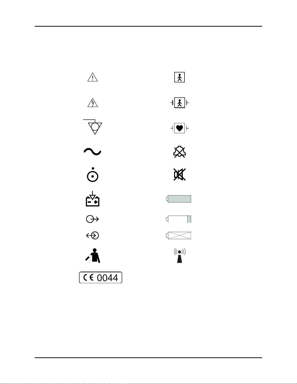
Symbols
SYMBOL DESCRIPTION SYMBOL DESCRIPTION
Attention, Consult
Accompanying Documents /
Refer to Manual
Type BF Equipment
Dangerous Voltage
Equipotentiality
Alternating Current (AC) Alarm Off
ON/OFF (only for a part
of the equipment)
Battery Charging Full Battery Indicator
Data Output Low Battery Indicator
Data Input/Output No Battery in Unit
Defibrillator Proof Type BF
Equipment
Defibrillator Proof Type CF
Equipment
Alarm Mute
NIBP Connection
A symbol designating compliance of the Trio monitor with the
Medical Device Directive (MDD) 93/42/EEC, Class II b device.
xii 0070-10-0666-01 Trio™ Operating Instructions
Non-ionizing electromagnetic
radiation
Page 16

1.0
General Product Description
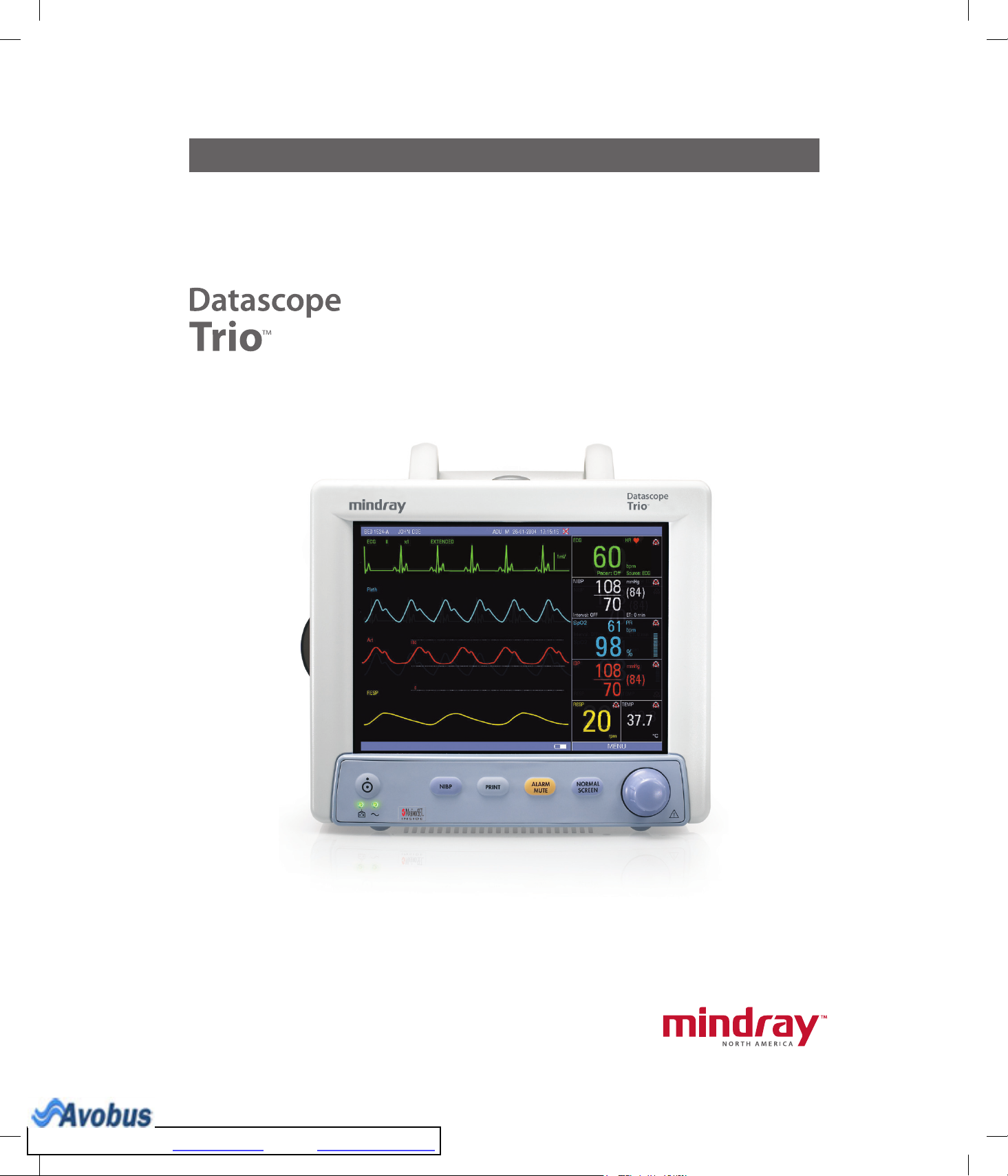
The Trio is a vital signs monitor intended for intra-hospital use on human patients. It is
adaptable for use with adult and pediatric patients. The Trio is a three (3) to four (4) trace
monitor. The unit has many features and functions, yet is easy to use through an integrated
keypad, Navigator
Panel Keypad for details.
™
Knob (see FIGURE 1-2) and an intuitive menu system. Refer to Front
The patient parameters that can be monitored with the Trio are: ECG (3-lead or 5-lead
selectable), SpO
The Trio is equipped with an 8.4" Color High Resolution (800 x 600) TFT LCD. Digital
displays are provided for Heart Rate, Pulse Rate, Pulse Oximetry (SpO2), Non-Invasive Blood
Pressure (NIBP), Respiration Rate and Temperature (T1). Waveform displays are provided for
ECG, Pleth and Respiration. An optional digital and waveform display for Invasive Blood
Pressure (IBP) is available. The optional built-in thermal recorder provides hard copies of all
digital data and waveforms, as well as Tabular and Graphic Trend information.
The Trio monitor can be mounted on a rolling stand, a wall mount bracket, a bed rail or
operated as a tabletop device.
The Trio is powered by an AC connection or an optional internal battery.
NOTE: The Trio is suitable for use in the presence of the discharge
NOTE: The Trio is suitable for use in the presence of electrosurgery.
NOTE: The Trio may not meet performance specifications if stored
, Non-Invasive Blood Pressure, Respiration and Temperature.
2
of a defibrillator.
or used outside of the specified environmental conditions
(see section 6.0).
Trio™ Operating Instructions 0070-10-0666-01 1 - 1
To Purchase, Visit Avobus.com or call 1-800-674-3655
Page 17

General Product Description
Key Features
The Trio offers several new features that enhance the capabilities of the monitor. The main
improvements of this release are as follows:
• Support for the full line of adult and pediatric NIBP Cuffs, see Section 5.
• Determination of heart rate from an NIBP measurement, see Section 2.
• An enhancement to SpO
monitoring that enables audible distinction of oxygen
2
saturation changes, see Section 2.
• A serial port that offers connectivity to various medical devices, see Section 1.
FEATURES STANDARD OPTIONAL
Display 8.4 inch color TFT LCD
4-trace erase bar refresh
ECG 3 or 5 Lead (I, II, III, aVR, aVL, aVF, V)
ECG Cascade
ESIS Capability (3 or 5 Lead)
Blood Pressure Non-Invasive Blood Pressure
SpO
2
Respiration Impedance
Temperature One YSI 400 channel
Trend Tabular and Graphic Trends up to 24 hours*
Power Internal isolated power module Sealed lead acid battery or
Printing Two-trace recorder
Communication Ethernet,
Other Handle with bedrail hook Wall mount and rolling stand
* When the monitor is powered OFF, the tabular and graphic trend data is maintained for 2 hours. If the
monitor remains OFF for more than 2 hours, the tabular and graphic trend data is deleted.
** Model number 0998-00-0600-4XXXX only
Masimo SET® SpO
Serial Communication Port (DIAP),**
Analog Output
Navigator
Dedicated keys
™
2
Knob
Nellcor® OxiMax® SpO
Lithium Ion battery
kits
2
1 - 2 0070-10-0666-01 Trio™ Operating Instructions
Page 18
General Product Description Front Panel
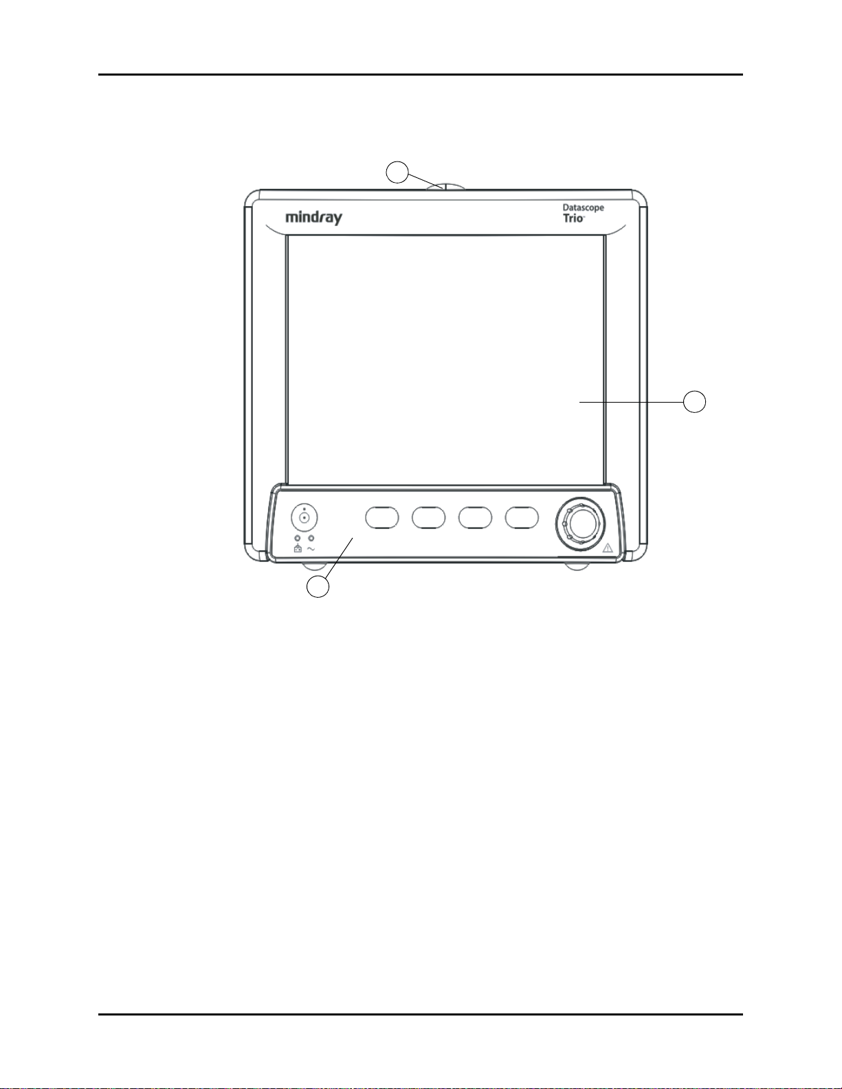
1.1 Front Panel
1
2
3
FIGURE 1-1 Front View of Monitor
1. Alarm Light
Illuminates when an alarm is triggered.
2. Display
8.4” color TFT LCD (800 x 600 resolution).
3. Front Panel Keypad
™
Navigator
Knob and dedicated quick-action keys.
Trio™ Operating Instructions 0070-10-0666-01 1 - 3
Page 19
Front Panel General Product Description
2
3
8
7
6
5
4
1
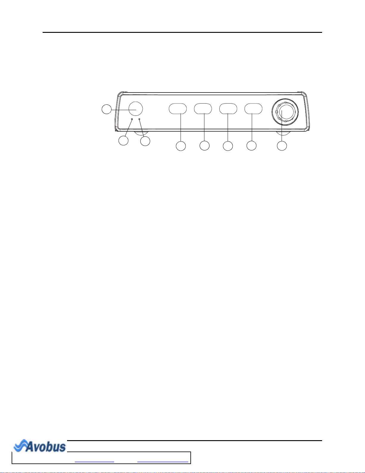
1.1.1 Front Panel Keypad
The front panel keypad is used to access many main functions quickly and easily (see
FIGURE 1-2).
FIGURE 1-2 Keypad
1. POWER Press this key to power the Trio ON or OFF.
NOTE: The power supply and battery
charger are active any time AC
power is supplied, regardless of
whether the monitor is ON or
OFF.
2. BATTERY
CHARGING
INDICATOR
A green LED that is illuminated when AC power is present and
the battery is installed and charging. When the monitor is
running on battery power, this LED does not illuminate. When
a “low battery” condition exists, this LED flashes at a constant
rate.
3. AC POWER
A green LED that is illuminated when AC power is present.
INDICATOR
4. NIBP Press this key to begin a NIBP measurement. During a
measurement, press this key to cancel the measurement and
deflate the cuff.
5. PRINT Press this key to initiate a real-time printout of numeric data
and selected waveforms. Results are output via the optional
internal printer. During a printing, press this key to cancel the
print job. Various print settings (such as speed and duration of
printout) are adjustable and may be set by accessing the
PRINTER SETUP menu in the MONITOR SETUP menu.
(Refer to section 2.3.5.3 for details).
1 - 4 0070-10-0666-01 Trio™ Operating Instructions
To Purchase, Visit Avobus.com or call 1-800-674-3655
Page 20

General Product Description Front Panel
6. ALARM MUTE Press this key to suspend audio alarms on all currently
alarming parameters. The alarms remain suspended for a user
selected amount of time as set in the ALARM SETUP menu or
until the alarm condition is no longer present. Any new alarms
that occur while the alarm tone is silenced will disable the
silence and sound the alarm tone. While the alarms are
suspended, an ALARM MUTE icon is displayed in the
message bar. When in ALARM MUTE mode, press this key
again to re-enable the audio alarm.
7. NORMAL
SCREEN
Press the key to close all open menus and return the normal
real-time display.
8. NAVIGATOR™
KNOB
Rotate this knob to highlight the various menus on the display.
When highlighted, the menu target will display as black text
on a white background. Available menu targets on the main
display include the MENU icon, ECG lead, ECG size, ECG
filter, IBP label, ECG, NIBP, SpO2, IBP, RESP and TEMP. Press
the knob to display the highlighted menu. Once a menu is
displayed, rotate the knob to highlight one of the items listed.
Press the knob to select the highlighted item.
• When it is not highlighted, the MENU icon will display as
white text on the footer background with a white outline.
When all other menu targets are not highlighted, they will
be displayed in the colors that are defined in the
PARAMETER COLORS menu.
• When navigating within a menu, the menu target will
display as black text on a white background. When the
menu target is selected by pressing the knob, it will display
as follows:
• If the menu target is a Drop-Down Box, it will open with
the current selection displayed in black text on a white
background. Rotate and press the knob as necessary to
make a selection.
• If the menu target is a Text Edit Box, a cursor will be
inserted in the menu target and the letter “A” in the
onscreen keypad will display in black text on a white
background. Rotate and press the knob as necessary to
input the desired text. Select “OK” in the onscreen
keypad to accept the text and return the cursor to the
Text Edit Box.
• If the menu target is a Spin Edit Box, it will display as
white text on a black background. Rotate and press the
knob as necessary to make a selection.
Trio™ Operating Instructions 0070-10-0666-01 1 - 5
Page 21
Front Panel General Product Description
1
4
3
5
2
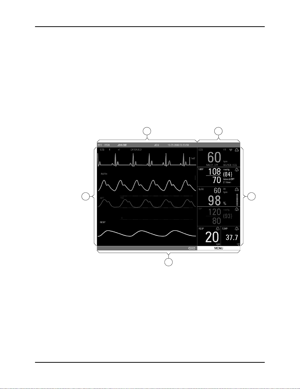
1.1.2 Display
The Trio display provides menus, waveforms, parameter information, patient information,
and messages. The Trio includes various features that enable the user to customize the
display. Additionally, the user default feature enables the user to save the customized
settings. The display is divided into the following areas (see FIGURE 1-3):
1. Demographics
2. Technical Alarms
3. Waveform Data/Menus
4. Parameter Tiles
5. Status Bar
FIGURE 1-3 Main Display
1. Demographics
The demographics area displays the following information:
Bed # Bed number (6 characters maximum)
First Name First name of the patient (10 characters maximum)
Last Name Last name of the patient (10 characters maximum)
Patient Size Size of the patient: ADU (Adult), PED (Pediatric)
1 - 6 0070-10-0666-01 Trio™ Operating Instructions
Page 22

General Product Description Front Panel
Gender Gender of the patient: M (Male), F (Female)
Current Date XX-XX-XXXX (month-day-year)
Current Time
XX:XX:XX (hours:minutes:seconds)
(24-hour format)
Indicates that all alarm tones have been manually disabled. It is
displayed when the ALARM MUTE button is pressed.
2. Technical Alarms
Technical Alarms are failures or errors that require resolution or attention to continue patient
monitoring (also called System Error Messages).
3. Waveform Data/Menus
The waveform data/menus area is used to display parameter waveforms and system menus.
Waveform Data
Up to four (4) waveforms may be displayed. When all waveforms are selected in the
TRACE SETUP menu, the waveforms will be displayed, from top to bottom, as follows:
ECG, SpO
(Pleth), IBP (optional), Respiration (RESP). (Refer to Trace Setup for details.)
2
Up to four (4) waveforms may be displayed on this monitor.
• If the parameter waveforms only include ECG, SpO2 (PLETH), and Respiration (RESP),
and the ECG cascade is set to OFF, then only three (3) waveforms will be displayed. If
the ECG cascade is set to ON, then four (4) waveforms will be displayed. The first two
(2) will be ECG.
• For those monitors in which IBP is ordered as an option, and the cascade is set to OFF,
the display will show four (4) waveforms: ECG, SpO
(PLETH), IBP, and Respiration
2
(RESP). If the ECG cascade is set to ON, then the cascaded ECG will replace the
(PLETH) waveform.
SpO
2
ECG Lead, Gain and Filter are displayed in the upper left corner of the main display. The
IBP waveform label is displayed in the upper left corner of the IBP waveform window.
The waveforms are refreshed according to the rate designated by the user. (Refer to
specific parameter sections for details of sweep speed.)
Menus
When performing menu functions, a menu will be displayed, potentially obstructing the
view of select waveforms. Select NORMAL SCREEN in the menu (or on the Front Panel
Keypad) to exit all menus and return to the normal screen. If the user does not perform
any screen operation for 30 seconds, the menu will be removed automatically and the
screen will return to the normal display mode. Trend displays do not time out.
Trio™ Operating Instructions 0070-10-0666-01 1 - 7
To Purchase, Visit Avobus.com or call 1-800-674-3655
Page 23
Front Panel General Product Description
A
C
B
FE
D
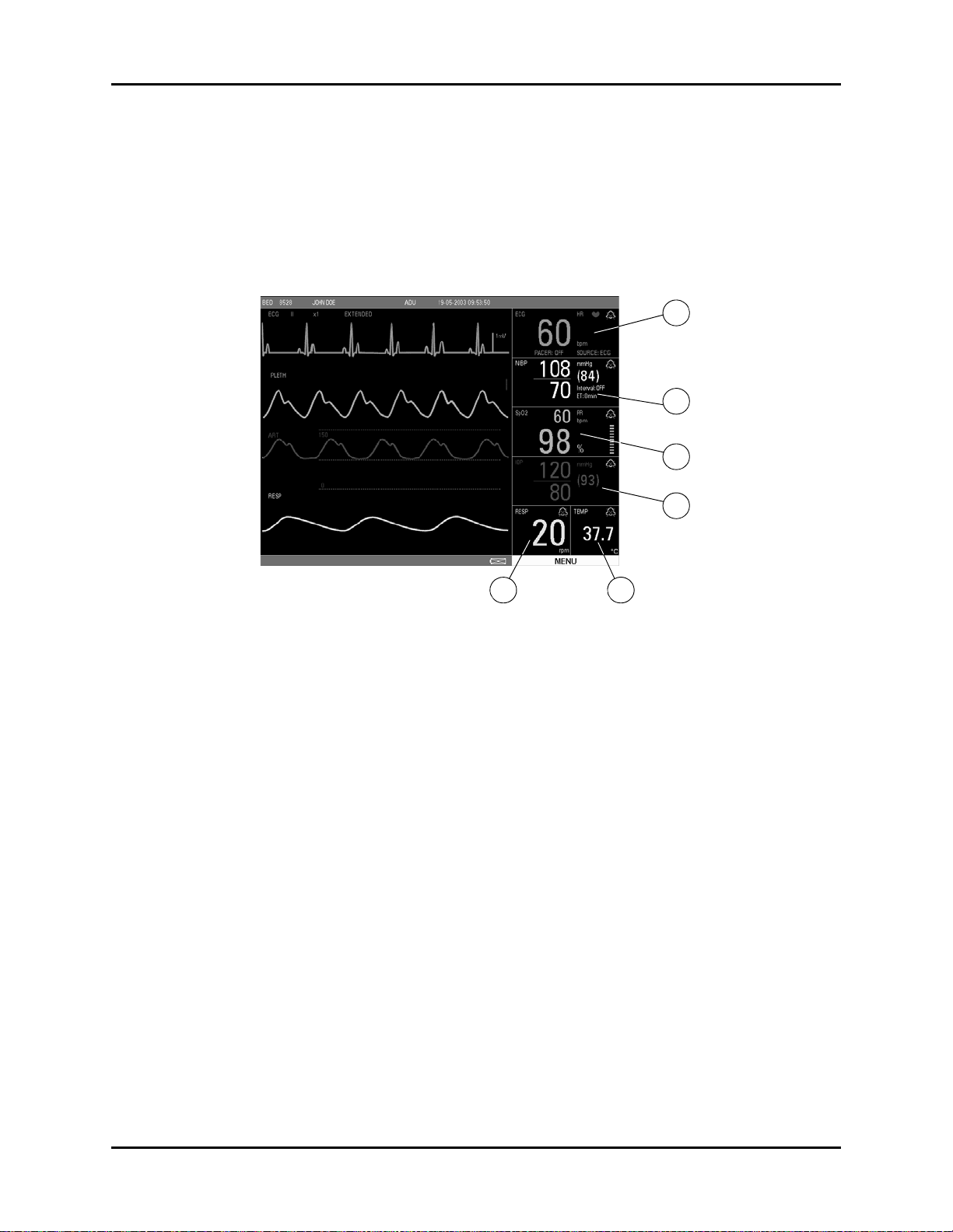
4. Parameter Tiles
The numeric data in each parameter tile refreshes continuously, except for the NIBP value,
which refreshes each time a measurement is completed (see section 6). Using the MODULE
SETUP menu, parameters can be turned ON or OFF, and the screen display will adjust
accordingly. The numeric data is displayed at fixed positions within each parameter tile. (see
FIGURE 1-4).
FIGURE 1-4 Parameter Tiles
A. ECG
• PACER Display (ON or OFF)
• Heart Rate (HR)/Pulse Rate (PR) (Unit: bpm)
B. NIBP
• Systolic, Diastolic, Mean (Units: mmHg or kPa)
• Interval Display (CONT, 1min, 2min, 3min, 4min, 5min, 10min, 15min, 30min, 1HR,
2HRS, 4HRS, OFF)
• Elapsed Time Display (ET)
C. SpO2
• Pulse Rate (PR) (Unit: bpm)
•SpO
(Unit: %)
2
• Pulse Amplitude Indicator
D. IBP
• Systolic, Diastolic, Mean (Units: mmHg or kPa)
E. RESP
• Respiration Rate (Units: rpm)
F. TEMP
• Temperature (Units: °C or °F)
1 - 8 0070-10-0666-01 Trio™ Operating Instructions
Page 24

General Product Description Front Panel
5. Status Bar
The status bar is located at the bottom of the screen. It displays the DEMO MODE status, the
battery icons and the MENU icon.
• The DEMO MODE status message indicates that the monitor is in demo mode and is
displaying simulated patient data.
• The battery icons indicate the relative charge status of the optional battery.
• Battery (Full)
The battery full icon appears in the lower right portion of the display when the unit is
operated by battery power. When the batteries are fully charged, the color will be
filled in as shown.
• Battery (Low)
The battery low icon appears in the lower right portion of the display when the unit is
operating on battery power. When the batteries are running low, color appears only
on the right portion of the indicator.
• No Battery in Unit
The no battery icon appears in the lower right portion of the display when a battery is
not installed in the monitor.
•The MENU icon is used to access the SYSTEM MENU. It is a rectangular icon
positioned below the parameter tiles and is the same width as that area.
Trio™ Operating Instructions 0070-10-0666-01 1 - 9
Page 25
Left Side Panel General Product Description
2
4
1
3
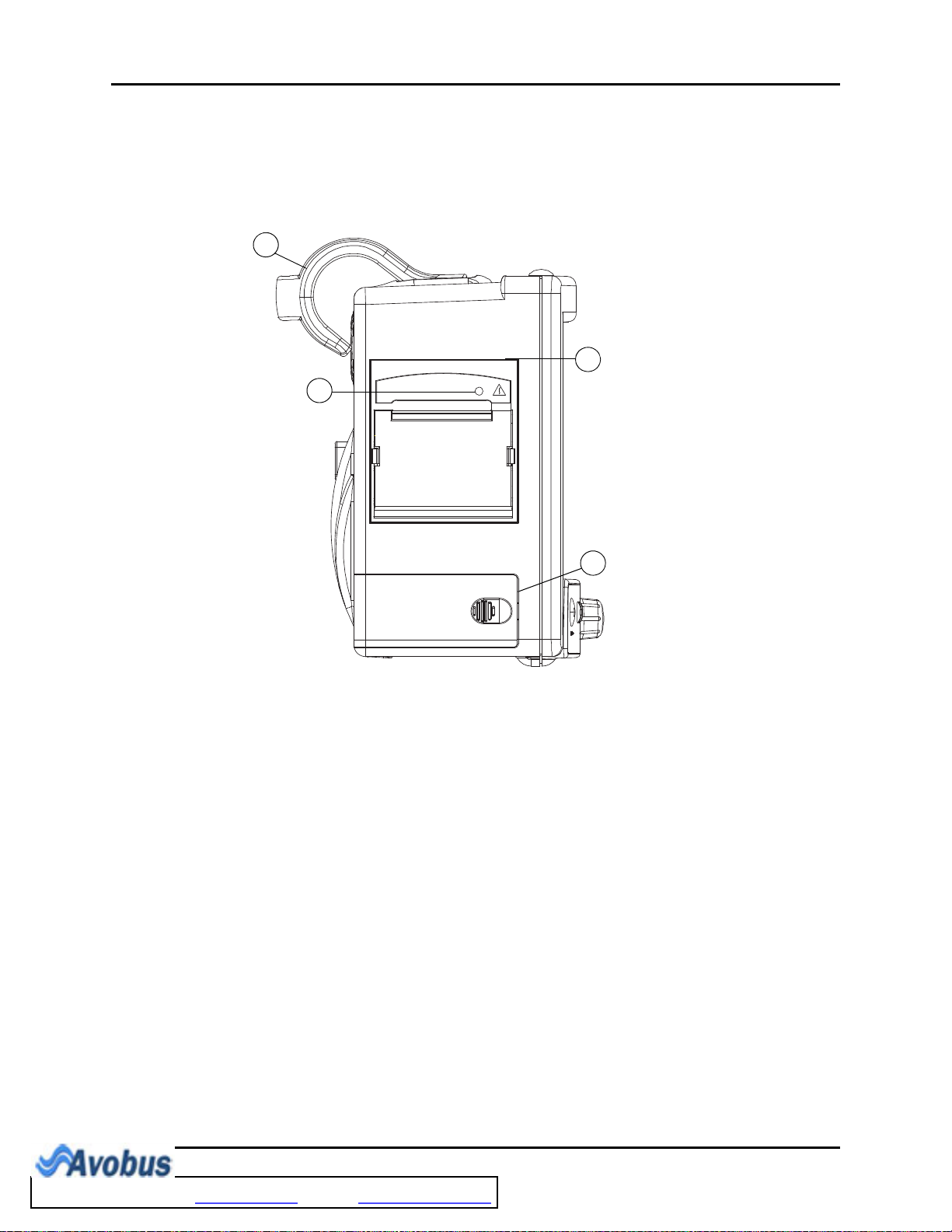
1.2 Left Side Panel
The optional, two-trace thermal strip chart recorder and the battery compartment are located
on the left side panel (see FIGURE 1-5).
FIGURE 1-5 Left Side Panel
1. Handle/bedrail hook
Handle with integrated bedrail hook
2. Recorder (Optional)
Two-trace thermal strip chart recorder
3. Recorder Power LED
A green LED that indicates that the recorder is receiving power
4. Battery compartment
The housing for the optional, user-replaceable, rechargeable battery (sealed lead acid or
Lithium Ion)
1 - 10 0070-10-0666-01 Trio™ Operating Instructions
To Purchase, Visit Avobus.com or call 1-800-674-3655
Page 26
General Product Description Right Side Panel
SpO
2
T1
IBP 1
ECG
¨
1
4
5
3
2
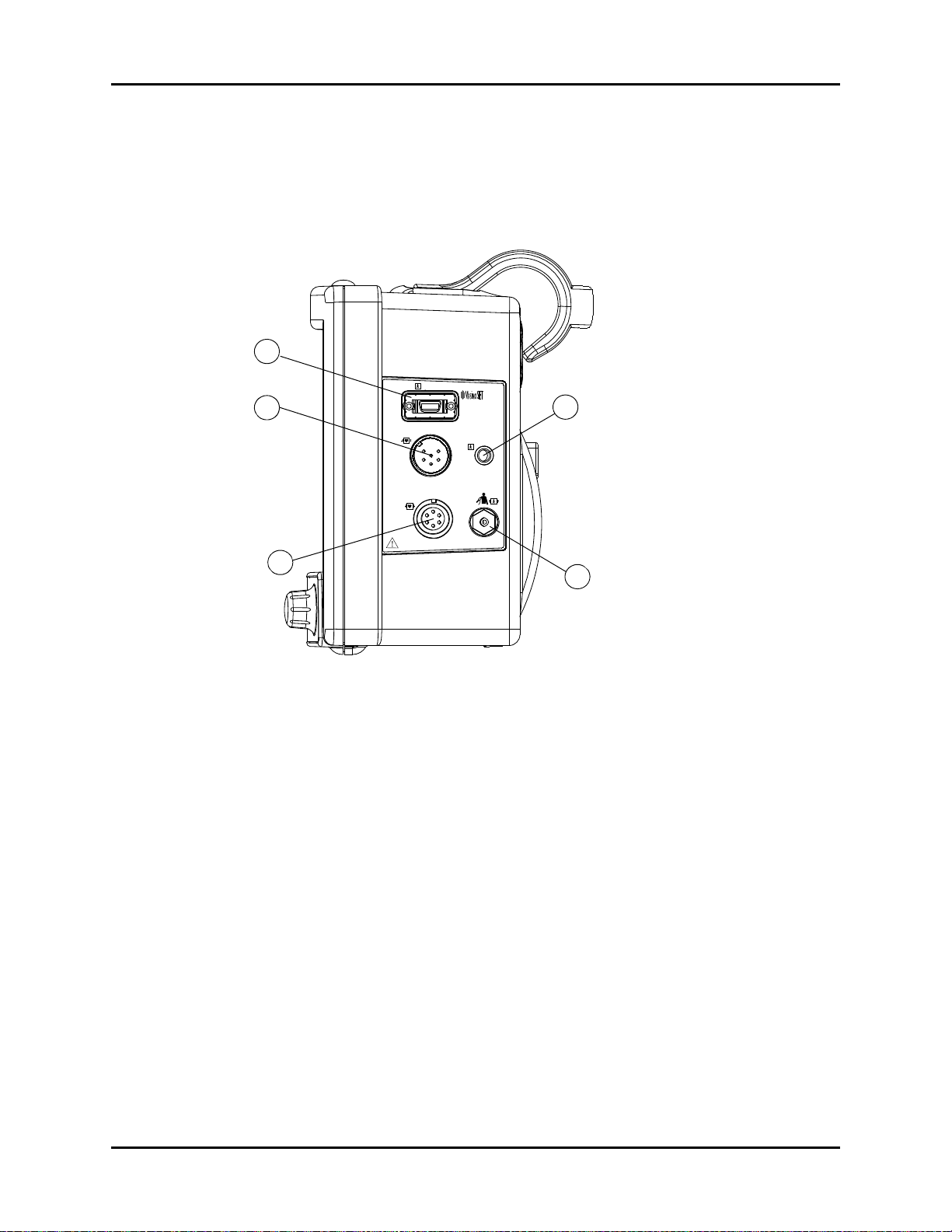
1.3 Right Side Panel
The connectors for patient cables and sensors are located on the right side panel
(see FIGURE 1-6).
FIGURE 1-6 Right Side Panel
1. SpO
This receptacle is used to attach the SpO
Receptacle
2
sensor to the monitor.
2
2. Optional IBP
A six-pin male receptacle used for an IBP connection.
3. ECG Receptacle
A six position female receptacle used to attach a 3 or 5 Lead ECG cable.
4. T1 Receptacle
A standard 1/4” phone jack is used to mate with the YSI series 400 temperature probe.
5. NIBP Quick-Connect Rectus* Pneumatic Fitting
This pneumatic fitting is used to attach the NIBP hose to the unit.
* Quick Connect Pneumatic Fittings available from Rectus-TEMA Corporation.
Trio™ Operating Instructions 0070-10-0666-01 1 - 11
Page 27
Rear Panel General Product Description
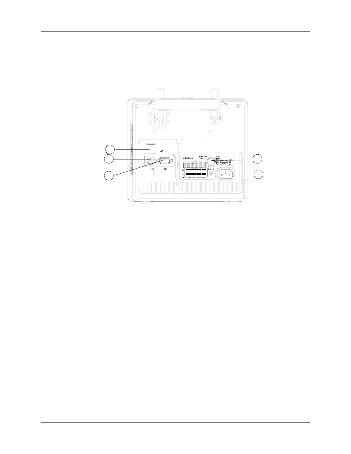
1.4 Rear Panel
The following connectors are located on the rear panel (see FIGURE 1-7).
1
2
3
CS1
4
AO1
SP1
XXXX- XX - XXXX - XXXXX
XXXX- XX - XXXX - XXXXX
5
FIGURE 1-7 Rear Panel
1. Ethernet Port (CS1)
The ethernet port is an RJ45 jack that is used for software upgrades.
NOTE: This port should not be used while monitoring a patient.
2. Analog Output (AO1)
The analog signal output connector may be used with a oscillometer, pen recorder or other
external devices (see section 4). The connector is a BNC jack.
NOTE: After connecting any external device to the Analog Output,
verify that leakage currents do not exceed accepted limits.
1 - 12 0070-10-0666-01 Trio™ Operating Instructions
Page 28

General Product Description Rear Panel
3. Serial Port (SP1) or VGA Output (RD1)
Trio monitors bearing a model number of 0998-00-0600-4XXXX are equipped with a
9-position D-shell serial port connector. Trio monitors bearing a model number of 0998-000600-0XXXX or 0998-00-0600-2XXXX are equipped with a 15-position D-Shell VGA output
connector.
The proprietary serial port is a 9-position D-shell plug connector with interface based on TIA/
EIA-232-F signal compliance. Information is transferred via DIAP protocol. (For additional
information see P/N 0070-00-0307).
The VGA output connector provides connectivity to a medical grade remote display. The
connector is a 15-position D-Shell connector. Connection to this port should be made with the
monitor power OFF. Power ON the monitor after powering ON the remote display.
NOTE: After connecting any external device to the Serial Port or the
VGA Output, verify that leakage currents do not exceed
accepted limits.
4. Equipotential Lug
The equipotential lug provides equipotential grounding for hospital equipment.
NOTE: Ensure that when connecting external devices to the unit all
equipotential terminals are connected.
5. AC Receptacle
Insert the AC power cord into this receptacle.
Trio™ Operating Instructions 0070-10-0666-01 1 - 13
To Purchase, Visit Avobus.com or call 1-800-674-3655
Page 29

Rear Panel General Product Description
This page intentionally left blank.
1 - 14 0070-10-0666-01 Trio™ Operating Instructions
Page 30

2.0
Operations
2.1 Getting Started
The Trio features default factory settings that enable monitoring to begin without setting
waveforms, parameters, alarms, or functions. Each of these settings can be changed based
on specific patient or departmental needs. Certain operating characteristics (e.g. NIBP start
pressure) are based on the selected patient size.
CAUTION: The patient size selection should be matched to the actual
patient before monitoring begins.
Before using the monitor, complete the following steps:
1. Examine the device, all external cables, inserted modules and accessories for damage
2. Check all monitor functions for proper operation.
NOTE: If the monitor is damaged, contact the biomedical engineer
of the hospital or Customer Service immediately.
2.1.1 Setting-up Patients
1. Turn the monitor ON using the POWER key on the front panel.
2. Remove all of the previous patient data (except BED # and SIZE) as follows:
a. Use the Navigator™ Knob to select the MENU icon located in the bottom right
corner of the screen. The SYSTEM MENU (FIGURE 2-1) is displayed.
b. From the SYSTEM MENU, select PATIENT SETUP. The PATIENT SETUP menu
(FIGURE 2-2) is displayed.
c. Select PATIENT DISCHARGE. A confirmation dialog is displayed with the prompt,
Discharge patient from monitor?.
d. Select YES to remove the previous patient data from the monitor.
3. Connect the patient to the monitor, apply appropriate accessories such as ECG
electrodes, NIBP cuff, SpO
probe, etc.
2
Trio™ Operating Instructions 0070-10-0666-01 2 - 1
Page 31

Menus Operations
4. Enter the desired patient information into the Trio via the PATIENT SETUP menu.
Select appropriate patient SIZE.
5. If desired, press the NIBP key to initiate a non-invasive blood pressure measurement.
6. When monitoring has concluded, clear the patient's data by selecting PATIENT
DISCHARGE from the PATIENT SETUP menu.
2.1.2 Setting the Clock (Date and Time)
From the MONITOR SETUP menu the date and time can be set.
1. Using the Navigator Knob, select the MENU icon located in the bottom right corner of
the display.
2. From the SYSTEM MENU select MONITOR SETUP.
3. Select TIME SETUP.
4. Select YEAR, MONTH, DAY, HOUR, MINUTE or SECOND and adjust accordingly.
5. Select PREVIOUS MENU to return to the previous menu or select NORMAL SCREEN
(from the menu or the Front Panel Keypad) to exit the menu and return to the normal
screen.
2.2 Menus
The Trio menu system is accessed using the Navigator™ Knob. The flexibility of the menu
system enables the configuration of various features including the monitored parameters,
waveform sweep speed, audio volume, and parameter colors.
The MENU icon located in the bottom right corner of the display provides access to the
SYSTEM MENU. The parameter menu label in each parameter tile provides access to its
user-definable settings. Parameter menus include: ECG, NIBP, SpO2, IBP (optional), RESP
and TEMP.
The menu system restricts the overlap of settings that adjust upper and lower alarm limits. The
menu targets for these limits will be Spin Edit Boxes. See the following example for further
explanation.
Example: if a lower limit is set to 82, the menu system will restrict the upper limit choices
from being 82 or less.
NOTE: All menus time-out after 30 seconds of inactivity with the
exception of the List Trend and Graphic Trend menus, which
display indefinitely until closed manually.
2 - 2 0070-10-0666-01 Trio™ Operating Instructions
To Purchase, Visit Avobus.com or call 1-800-674-3655
Page 32

Operations System Menu
2.3 System Menu
The SYSTEM MENU provides the following submenu choices: PATIENT SETUP, LIST
TREND, GRAPHIC TREND, MARK EVENT, MONITOR SETUP, MAINTENANCE, and
NORMAL SCREEN. For the default settings of all menu selections, refer to section 3.0,
“Defaults”.
Use the Navigator Knob to select the MENU icon in the lower right corner of the screen. The
SYSTEM MENU (FIGURE 2-1) is displayed. From the SYSTEM MENU, select a submenu.
FIGURE 2-1 System Menu
2.3.1 Patient Setup
Select PATIENT SETUP from the SYSTEM MENU. The PATIENT SETUP menu (FIGURE 2-
2) is displayed.
FIGURE 2-2 Patient Setup Menu
Trio™ Operating Instructions 0070-10-0666-01 2 - 3
Page 33

System Menu Operations
The PATIENT SETUP menu provides the following choices for entering patient demographic
information and for patient discharge.
NOTE: The ID #, BED#, FIRST NAME and LAST NAME use the on-
screen keypad to enter demographic information. The
remaining demographic information is chosen from DropDown or Spin Edit Boxes.
ID # Select to enter the patient ID number (only appears on recorder printouts)
BED# Select to enter the patient bed number
FIRST NAME Select to enter the patient's first name
LAST NAME Select to enter the patient's last name
GENDER Select to enter the patient gender (choices are: F for Female, M for Male)
SIZE Select to enter the patient size (choices are: ADU for Adult and PED
for Pediatric)
BIRTH Select to enter the patient date of birth (format: year/month/day)
HT. (cm) Select to enter the patient height
WT. (kg) Select to enter the patient weight
PATIEN T
DISCHARGE
Select to discharge the current patient and admit a new patient. Selecting
PATIENT DISCHARGE
The user is prompted to answer
opens the confirmation dialog box (FIGURE 2-3).
YES
or NO to the question:
Discharge
patient from monitor?
Select YES to discharge the current patient from the monitor, erase the
stored record of the current patient (except BED # and SIZE) and exit the
menu. Select NO to continue monitoring the current patient, maintain the
stored record of the current patient and exit the menu.
NOTE: Selecting YES will delete all information
related to the currently monitored patient.
FIGURE 2-3 Confirmation Dialog Box
2 - 4 0070-10-0666-01 Trio™ Operating Instructions
Page 34

Operations System Menu
Entering the ID #, BED#, FIRST NAME and LAST NAME
Use the onscreen keypad to enter the ID #, BED#, FIRST NAME and LAST NAME
information, proceed as follows:
1. Select the PATIENT SETUP menu and use the Navigator™ Knob to scroll to the item
that will be entered or changed.
2. Press the Navigator Knob and the cursor will automatically move to the on-screen
keypad.
3. Move the cursor to the appropriate character and press the knob so that the character
appears in the box above. Continue this technique until the information for that item is
complete.
NOTE: Select DEL to delete incorrect characters.
4. When finished entering the data for a particular item, select OK. The patient
information will be displayed in the box for that menu item and the cursor will return
to the starting position.
5. Select PREVIOUS MENU to return to the previous menu. Select NORMAL
SCREEN (from the menu or the Front Panel Keypad) to exit the menu and return to the
normal screen.
Entering the GENDER, SIZE, BIRTH DATE, HEIGHT and WEIGHT.
Use the Drop-Down and Spin Edit Boxes to enter the GENDER, SIZE, BIRTH, HT. and WT.
information, proceed as follows:
NOTE: Setting the SIZE will automatically select all user defined
1. Select the PATIENT SETUP menu and use the Navigator™ Knob to scroll to the item
2. Press the Navigator Knob to access the Drop-Down or Spin Edit box for that selection.
3. Scroll to the desired setting and press the knob to accept the selection.
4. Select PREVIOUS MENU to return to the previous menu. Select NORMAL
defaults for that patient size.
that will be entered or changed.
SCREEN (from the menu or the Front Panel Keypad) to exit the menu and return to the
normal screen.
2.3.2 List Trend
To access the LIST TREND menu/display, select LIST TREND from the SYSTEM MENU.
Refer to "Trends" on page 2-76 for details on List Trend functions.
2.3.3 Graphic Trend
To access the GRAPHIC TREND menu/display, select GRAPHIC TREND from the
SYSTEM MENU. Refer to "Trends" on page 2-76 for details on Graphic Trend functions.
Trio™ Operating Instructions 0070-10-0666-01 2 - 5
To Purchase, Visit Avobus.com or call 1-800-674-3655
Page 35

System Menu Operations
2.3.4 Mark Event
The Mark Event function places a time stamp event marker (A, B, C or D) in the trend
memory. This function may be used to identify medication delivery, change in patient status,
etc. There may be a time delay between the time at which the event is marked and the point
in time at which it displays on the trend screen.
Select MARK EVENT from the SYSTEM MENU (see FIGURE 2-4).
FIGURE 2-4 Mark Event Menu
To mark an event, use the Navigator™ Knob to select EVENT A, B, C or D. Once an event
is marked, the @ symbol appears in the event box. To cancel the selection, move the cursor to
the event and press the knob again. Select PREVIOUS MENU to save the marked event,
exit the MARK EVENT menu and return to the previous menu. Select NORMAL SCREEN
(from the menu or the Front Panel Keypad) to save the marked event, to exit the menu and
return to the normal screen.
NOTE: Marked Events will not be saved if the menu times out.
2.3.5 Monitor Setup
1. Select MONITOR SETUP from the SYSTEM MENU. The MONITOR SETUP menu,
containing various submenus (FIGURE 2-5), is displayed.
FIGURE 2-5 Monitor Setup Menu
2 - 6 0070-10-0666-01 Trio™ Operating Instructions
Page 36

Operations System Menu
2.3.5.1 Alarm Setup
Select ALARM SETUP from the MONITOR SETUP menu (see FIGURE 2-5).
The ALARM SETUP menu allows the user to adjust various alarm functions. Refer to section
2.5, “Alarms” for details on Alarm functions.
2.3.5.2 Time Setup
From the MONITOR SETUP menu, select the TIME SETUP menu to modify the time and
date settings displayed on the monitor (see FIGURE 2-6). The TIME SETUP menu allows the
user to set the YEAR, MONTH, DAY, HOUR, MINUTE and SECOND. Use the
Navigator™ Knob to adjust settings accordingly. Select PREVIOUS MENU to exit the TIME
SETUP menu and return to the previous menu. Select NORMAL SCREEN (from the menu or
the Front Panel Keypad) to exit the menu and return to the normal screen.
FIGURE 2-6 Time Setup Menu
Trio™ Operating Instructions 0070-10-0666-01 2 - 7
Page 37

System Menu Operations
2.3.5.3 Printer Setup
Select PRINTER SETUP from the MONITOR SETUP (see FIGURE 2-7).
FIGURE 2-7 Printer Setup Menu
Printer Setup Menu Selections
WAVEFORM 1 or
WAVEFORM 2
The PRINTER SETUP menu allows the user to designate which two
(2) parameter waveforms are displayed on the printout as
WAVEFORM 1 and WAVEFORM 2. Only waveforms that are
displayed on screen are available for selection.
Available parameter waveform selections include:
ECG: ECG waveform
: SpO2 Plethysmogram
SpO
2
IBP: IBP waveform (optional)
RESP: Respiration waveform
OFF: No display for this waveform
NOTE: Two (2) waveforms can not be set to
the same parameter. Attempting to
set a duplicate parameter will cause
the previous selection to default to
the next available parameter
waveform.
2 - 8 0070-10-0666-01 Trio™ Operating Instructions
To Purchase, Visit Avobus.com or call 1-800-674-3655
Page 38

Operations System Menu
TIME TIME represents the length of recording time. There are two (2)
selections available: CONTINUAL and 8s. CONTINUAL means
once the user presses the PRINT key on the front panel, the
recorder will continuously print out the selected waveform(s) until the
button is pressed again. 8s indicates a waveform recording time
length of 8 seconds.
INTERVAL INTERVAL represents the time interval between the start of recorder
activations. The following 10 selections are available: OFF,
10min, 20min, 30min, 40min, 50min, 1HR, 2HRS, 3HRS
and 4HRS. The system will initiate the print operation according to
the selected time interval. All interval waveform printouts are 8
seconds in length.
NOTE: A real-time printout (based on TIME
as described in the previous menu)
takes priority over a printout based
on INTERVAL.
SPEED SPEED is used to select the speed at which the paper advances in
the printer. There are two (2) options: 25.0 and 50.0 mm/s.
GRID GRID is used to select output format: OFF produces a printout
without a background grid, and ON produces a printout with a
background grid.
CLEAR PRINT
TASK
CLEAR PRINT TASK is used to clear all print tasks from the
recorder. This can be used, for example, when multiple alarm print
tasks are triggered simultaneously.
NOTE: The recorder is optional.
Select PREVIOUS MENU to return to the previous menu. Select NORMAL SCREEN (from
the menu or the Front Panel Keypad) to exit the menu and return to the normal screen.
Trio™ Operating Instructions 0070-10-0666-01 2 - 9
Page 39

System Menu Operations
2.3.5.4 Analog Setup
The monitor can output an analog waveform from the analog output connector (AO1) on the
rear panel.
Select ANALOG SETUP from the MONITOR SETUP menu (see FIGURE 2-8). Select
ANALOG OUT, to set analog out to ON or OFF. Select ANALOG WAVE to select the
parameter waveform output. Choices are ECG and IBP (optional).
Select PREVIOUS MENU to return to the previous menu. Select NORMAL SCREEN (from
the menu or the Front Panel Keypad) to exit the menu and return to the normal screen.
FIGURE 2-8 Analog Setup Menu
2.3.5.5 Module Setup
MODULE SETUP allows the user to customize the display by selecting the parameters to be
monitored. Select MODULE SETUP from the MONITOR SETUP menu (see FIGURE 2-9).
FIGURE 2-9 Module Setup Menu
Select the parameters to monitor by using the Navigator™ Knob to select the item to be
displayed. A check mark will be displayed in the box next to each parameter selected. To
deselect a parameter, press the knob again (the check mark will be removed). Select
PREVIOUS MENU to return to the previous menu. Select NORMAL SCREEN (from the
menu or the Front Panel Keypad) to exit the menu and return to the normal screen.
NOTE: If the optional IBP is not installed, it will not be displayed in
2 - 10 0070-10-0666-01 Trio™ Operating Instructions
the MODULE SETUP menu.
Page 40

Operations System Menu
2.3.5.6 Trace Setup
TRACE SETUP allows the user to choose the traces that will be displayed in the waveform
area and to choose the viewing mode. The viewing modes improve the viewability of the
display depending on how the Trio is positioned for use. There are two viewing modes that
can be selected from the WAVE DISPLAY pull-down menu.
• MODE 1 – provides an enhanced view angle and a less smooth wave. This mode should
be used when the Trio is being viewed from an angle. In most instances, this mode will
provide optimal viewing of waveform data. (MODE 1 is the factory default setting.)
• MODE 2 – provides a basic view angle and a smooth wave. This mode should be used
when the Trio is wall-mounted and being viewed from below.
1. Select TRACE SETUP from the MONITOR SETUP menu. The TRACE SETUP menu
(FIGURE 2-10) is displayed.
FIGURE 2-10 Trace Setup Menu
2. Use the Navigator™ Knob to select each parameter waveform (a check mark in the box
next to a parameter indicates that it has been selected). To deselect a parameter
waveform, press the knob again.
3. Choose the desired viewing mode from the WAVE DISPLAY pull-down menu.
4. Select PREVIOUS MENU to return to the previous menu. Select NORMAL SCREEN
(from the menu or the Front Panel Keypad) to exit the menu and return to the normal
screen.
NOTE: If the optional IBP is not installed, it will not be provided as
a choice in the TRACE SETUP menu.
Trio™ Operating Instructions 0070-10-0666-01 2 - 11
To Purchase, Visit Avobus.com or call 1-800-674-3655
Page 41

System Menu Operations
2.3.5.7 Parameter Colors
1. Select PARAMETER COLORS from the MONITOR SETUP menu. The PARAMETER
COLORS menu (FIGURE 2-11) is displayed. From this menu, the colors for displayed
parameters can be selected. The numeric and waveform data for each parameter
displays in the same color, as selected by the user. The color choices are: GREEN, RED,
YELLOW, BLUE, and WHITE.
FIGURE 2-11 Parameter Colors Menu
2. Select PREVIOUS MENU to return to the previous menu. Select NORMAL SCREEN
(from the menu or the Front Panel Keypad) to exit the menu and return to the normal
screen.
2.3.5.8 Restore Defaults
1. Select RESTORE DEFAULTS from the MONITOR SETUP menu. The RESTORE
DEFAULTS menu (FIGURE 2-12) is displayed.
FIGURE 2-12 Restore Defaults Menu
The RESTORE DEFAULTS menu allows the user to perform the following two (2) functions:
•The RESTORE USER DEFAULTS function allows the user to revert back to a previously
saved group of monitor settings for the selected patient size.
•The RESTORE FACTORY DEFAULTS function allows the user to revert back to the group
of monitor settings initially set by the manufacturer. Factory alarm defaults for each
parameter are indicated in the parameter sections to follow. (See section 3.0 “Defaults”
for a complete list of Factory Default Settings.)
2. Select PREVIOUS MENU to return to the previous menu. Select NORMAL SCREEN
(from the menu or the Front Panel Keypad) to exit the menu and return to the normal
screen.
2 - 12 0070-10-0666-01 Trio™ Operating Instructions
Page 42

Operations System Menu
2.3.5.9 Save Current
SAVE CURRENT allows the user to save the current customized settings as the default
settings (or the “User Default Configuration”), replacing the existing user-defined
configuration for the current patient size.
1. Select SAVE CURRENT from the MONITOR SETUP menu. The confirmation dialog
box in FIGURE 2-13 is displayed.
2. Select YES to replace the existing user-defined configuration with the current customized
settings. Select NO to cancel the task.
FIGURE 2-13 Confirmation Dialog Box
2.3.6 Maintenance
Refer to the Trio Service Manual (Part Number 0070-00-0627-03) for details on
maintenance functions.
2.3.7 Normal Screen
Select NORMAL SCREEN to exit the SYSTEM MENU and return to the normal screen.
Trio™ Operating Instructions 0070-10-0666-01 2 - 13
Page 43

Parameter Menus Operations
2.4 Parameter Menus
2.4.1 Electrocardiogram (ECG) Monitoring
ECG is a continuous waveform of a patient's cardiac electrical activity. The ECG waveform
will display in the first waveform area of the Trio.
The quality of an ECG signal is directly affected by electrode site skin preparation, electrode
patch quality and ECG lead placement. If artifact is present on the ECG waveform, then the
arrhythmia processing, alarm processing, and quality of the monitoring function may be
affected. The presence of artifact can prevent the monitor from establishing an accurate ECG
reference waveform, increasing the difficulty experienced in assessing the ECG rhythm.
Optimizing the ECG signal is imperative for accurate monitoring. Use high quality
electrodes, designed to acquire the ECG with excellent base line stability, recovery from
defibrillation and minimum artifact from patient movement.
With the Trio, ECG can be obtained by using either a 3 Lead or 5 Lead ECG cable in
conjunction with a lead set and skin electrodes. For best performance and safety, inspect the
ECG cables and electrodes daily.
WARNING: Ensure that the conductive parts of ECG electrodes do not
contact other conductive parts, including earth ground.
CAUTION: To avoid possible damage to the Trio, use only approved
ECG cables and approved accessories.
CAUTION: Line isolation transients may resemble actual cardiac
waveforms, thus inhibiting heart rate alarms. Check lead
wires for damage and ensure good skin contact prior to and
during use. Always use fresh electrodes and follow proper
skin preparation techniques.
CAUTION: Use of accessories, transducers and cables other than those
specified in the manual may result in increased
Electromagnetic Emissions or decreased Electromagnetic
Immunity of the Trio. It can also cause delayed recovery
after the discharge of a cardiac defibrillator.
NOTE: This device is not intended for direct cardiac application.
2.4.1.1 Skin Preparation
Proper skin preparation is essential in obtaining an accurate ECG reading. Electrode sites
should be clean and dry and should provide a smooth flat surface. Incidental electrical
activity and inaccurate readings may arise from incorrect skin preparation.
The following procedure is recommended for secure electrode patch application:
1. Shave the hair from the electrode sites in a circular area with a diameter of 2 – 4 inches.
2. Use a dry gauze pad to remove excess skin oils, skin cells and residue from the
electrode sites. Never rub the skin until it is raw or bleeding.
2 - 14 0070-10-0666-01 Trio™ Operating Instructions
To Purchase, Visit Avobus.com or call 1-800-674-3655
Page 44

Operations Parameter Menus
NOTE: Prepare the electrode site with alcohol only if the skin is
extremely greasy. If alcohol is used as a drying agent,
always allow the skin to dry before placing the electrode
patch on the skin.
2.4.1.2 Electrode Patch Location
NOTE: Store electrode patches at room temperature and open just
prior to use.
NOTE: Avoid more than one type of electrode on a patient because
of variations in electrical resistance.
NOTE: Avoid placing electrode patches directly over bone
prominences or over any high activity movement areas such
as shoulders or arms because muscle motion produces
electrical activity. If an electrode patch is placed over a large
muscle such as the pectorals, the monitor may detect this
additional muscle activity and could lead to false
arrhythmia calls.
1. To prevent evaporation of the contact gel medium, peel the backing off of the electrode
patch only when it is ready for use. Visually inspect the contact gel medium for
moistness. If the gel medium is not moist, do not use the electrode patch. Dry electrode
patches are not conductive.
NOTE: If using the snap type electrode wires, attach the electrode
patch to the lead wire before placing patch on the patient.
2. Attach the electrode patch to the skin at the prepared site. Smooth the electrode patch
down in a circular motion to ensure proper skin contact. If using soft gel electrodes,
never push down directly over the contact gel medium as this may displace the gel and
cause monitoring artifact. If using hard gel electrodes, it is recommended that during
application, the center of the electrode should be slightly pressed onto the skin to ensure
direct contact. Consult the electrode patch manufacturer’s instructions for specific use.
3. Secure the lead wires to the patient according to hospital practice. For additional
information see section 2.4.1.3, “Lead Placement”.
WARNING: Ensure that the ECG lead wires are neatly secured in a
manner that will prevent them from encircling the patient’s
neck, creating a strangulation hazard.
NOTE: It is recommended that electrode patches be changed at
least every 24 – 36 hours to maintain proper contact with
the skin. Some patients may require electrodes to be
changed more often. Electrode patches are disposable and
should be applied only once. Try to avoid reusing the exact
same electrode site during reapplication. If an electrode
becomes wet with fluid, change the electrode patch.
Trio™ Operating Instructions 0070-10-0666-01 2 - 15
Page 45
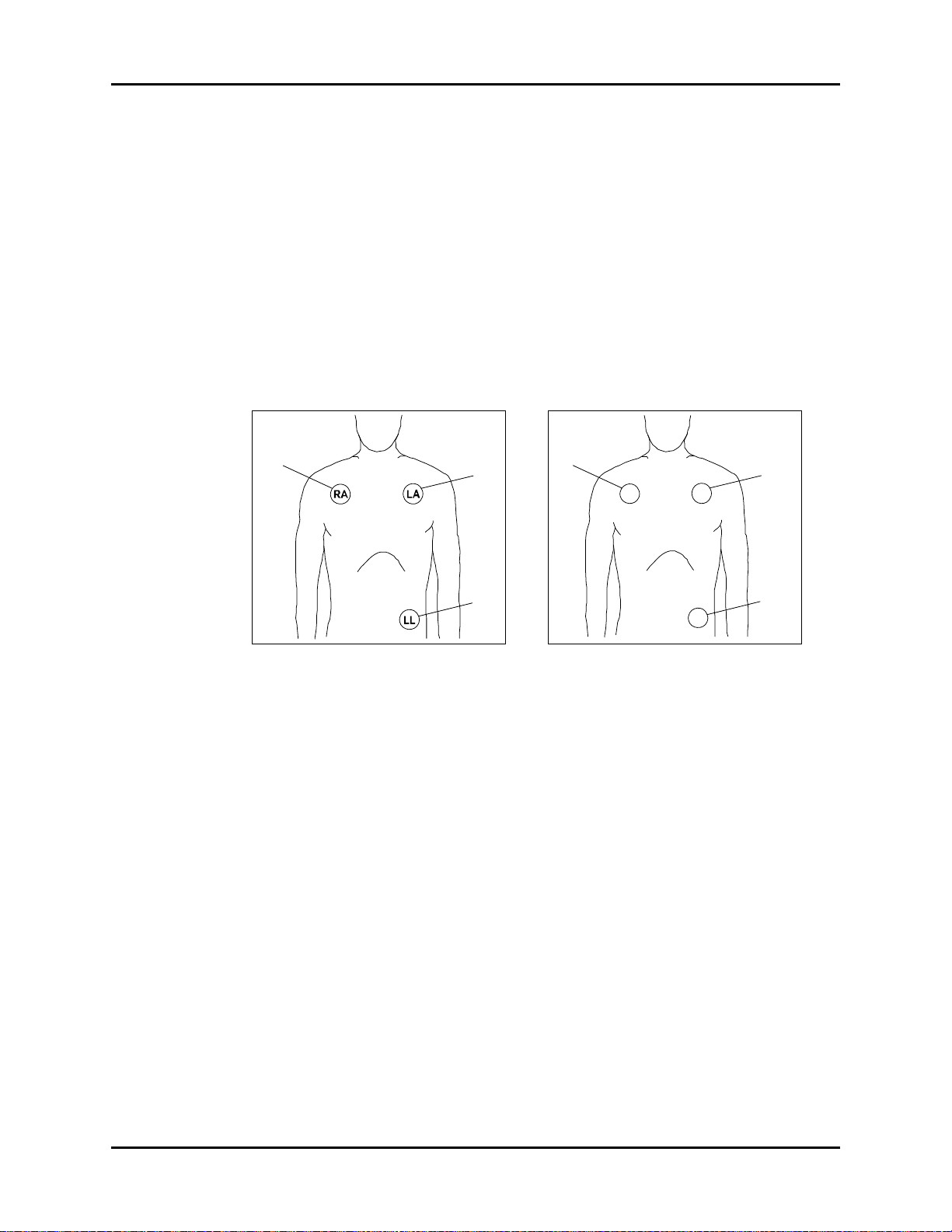
Parameter Menus Operations
White
Black
Red
Red
Yel l ow
Green
R
L
F
2.4.1.3 Lead Placement
The computerized arrhythmia algorithm works best when the patient’s R wave is significantly
larger than the P wave or the T wave. If the R wave is not significantly larger than other lower
voltage waves on the ECG tracing, the computer may have some difficulty in identifying the
appropriate waves. On some patients, electrode patch placement and/or the viewed ECG
lead may need to be adjusted in order to obtain a significant R wave.
This section outlines lead placement according to the guidelines of the American Heart
Association (AHA) and the International Electro-Technical Commission (IEC).
Standard 3-wire Lead Sets
Standard 3-wire lead sets include 3 ECG leads (I, II and III). Only 1 lead is monitored.
FIGURE 2-14 3-wire Lead Placement
(AHA)
• Place the RA (white) electrode under the
patient’s right clavicle, at the midclavicular line within the rib cage frame.
• Place the LA (black) electrode under the
patient’s left clavicle, at the midclavicular line within the rib cage frame.
• Place the LL (red) electrode on the
patient’s lower left abdomen within the
rib cage frame.
FIGURE 2-15 3-wire Lead Placement
(IEC)
• Place the R (red) electrode under the
patient’s right clavicle, at the midclavicular line within the rib cage frame.
• Place the L (yellow) electrode under the
patient’s left clavicle, at the midclavicular line within the rib cage frame.
• Place the F (green) electrode on the
patient’s lower left abdomen within the
rib cage frame.
2 - 16 0070-10-0666-01 Trio™ Operating Instructions
Page 46

Operations Parameter Menus
Black
White
RA
RL
Brown
V Lead
(any V position)
LA
Green
LL
Red
V
Yellow
Red
R
N
White
C Lead
(any position)C
L
Black
F
Green
C
Standard 5-wire Lead Sets
Standard 5-wire lead sets monitor 7 ECG leads: I, II, III, aVR, aVL, aVF and V.
FIGURE 2-16 5-wire Lead Placement
(AHA)
• Place the RA (white) electrode under the
patient’s right clavicle, at the midclavicular line within the rib cage frame.
• Place the LA (black) electrode under the
patient’s left clavicle, at the midclavicular line within the rib cage frame.
• Place the LL (red) electrode on the
patient’s lower left abdomen within the
rib cage frame.
• Place the RL (green) electrode on the
patient’s lower right abdomen within the
rib cage frame.
• Place the V (brown) electrode in one of
the V-lead positions (V1 – V6) depicted
in the following section.
FIGURE 2-17 5-wire Lead Placement
(IEC)
• Place the R (red) electrode under the
patient’s right clavicle, at the midclavicular line within the rib cage frame.
• Place the L (yellow) electrode under the
patient’s left clavicle, at the midclavicular line within the rib cage frame.
• Place the F (green) electrode on the
patient’s lower left abdomen within the
rib cage frame.
• Place the N (black) electrode on the
patient’s lower right abdomen within the
rib cage frame.
• Place the C (white) electrode in one of
the C-lead (C1 – C6) positions depicted
in the following section.
To Purchase, Visit Avobus.com or call 1-800-674-3655
Trio™ Operating Instructions 0070-10-0666-01 2 - 17
Page 47

Parameter Menus Operations
V-Lead and C-Lead Electrode Positions
FIGURE 2-18 V-Lead Electrode Placement
(AHA)
• V1 - Place the electrode at the
fourth intercostal space, on the right
sternal border
• V2 - Place the electrode at the
fourth intercostal space, on the left
sternal border
• V3 - Place the electrode midway
between V2 and V4 on a line joining
these 2 locations
• V4 - Place the electrode at the
fifth intercostal space on the midclavicular line
• V5 - Place the electrode at the fifth
intercostal space on the anterior
axillary line
• V6 - Place the electrode at the fifth
intercostal space on the mid-axillary line
FIGURE 2-19 C-Lead Electrode Placement
(IEC)
• C1 - Place the electrode at the
fourth intercostal space, on the right
sternal border
• C2 - Place the electrode at the
fourth intercostal space, on the left
sternal border
• C3 - Place the electrode midway
between C2 and C4 on a line joining
these 2 locations
• C4 - Place the electrode at the
fifth intercostal space on the midclavicular line
• C5 - Place the electrode at the fifth
intercostal space on the anterior
axillary line
• C6 - Place the electrode at the fifth
intercostal space on the mid-axillary line
2 - 18 0070-10-0666-01 Trio™ Operating Instructions
Page 48

Operations Parameter Menus
White
Black
Red
Red
Yellow
Green
R
L
F
Lead II Monitoring
FIGURE 2-20 Lead II Monitoring (AHA) FIGURE 2-21 Lead II Monitoring (IEC)
• Place the RA (white) electrode under the
patient’s right clavicle, at the midclavicular line within the rib cage frame.
• Place the LA (black) electrode under the
patient’s left clavicle, at the midclavicular line within the rib cage frame.
• Place the LL (red) electrode on the
patient’s lower left abdomen within the
rib cage frame.
• Place the R (red) electrode under the
patient’s right clavicle, at the midclavicular line within the rib cage frame.
• Place the L (yellow) electrode under the
patient’s left clavicle, at the midclavicular line within the rib cage frame.
• Place the F (green) electrode on the
patient’s lower left abdomen within the
rib cage frame.
Select ECG Lead II on the monitor. Lead II is
the direct electrical line between the RA
(white) electrode and the LL (red) electrode.
Select ECG Lead II on the monitor. Lead II is
the direct electrical line between the R (red)
electrode and the F (green) electrode.
Trio™ Operating Instructions 0070-10-0666-01 2 - 19
Page 49

Parameter Menus Operations
LL
LA
RA
White
Red
Black
F
L
R
Red
Green
Yellow
Modified Chest Lead (MCL) Monitoring
FIGURE 2-22 MCL Monitoring with a
3-wire Lead Set (AHA)
• Place the RA (white) electrode under the
patient’s left clavicle, at the midclavicular line within the rib cage frame.
• Place the LA (black) electrode on the
right sternal border, at the fourth
intercostal space within the rib cage
frame.
• Place the LL (red) electrode on the
patient’s lower left abdomen within the
rib cage frame.
Select ECG Lead I for MCL
monitoring.
1
Lead I is the direct electrical line between
the RA (white) electrode and the LA (black)
electrode.
Select ECG Lead II for MCL
monitoring.
6
Lead II is the direct electrical line between
the RA (white) electrode and the LL (red)
electrode.
FIGURE 2-23 MCL Monitoring with a
3-wire Lead Set (IEC)
• Place the R (red) electrode under the
patient’s left clavicle, at the midclavicular line within the rib cage frame.
• Place the L (yellow) electrode on the
right sternal border, at the fourth
intercostal space within the rib cage
frame.
• Place the F (green) electrode on the
patient’s lower left abdomen within the
rib cage frame.
Select ECG Lead I for MCL
monitoring.
1
Lead I is the direct electrical line between
the R (red) electrode and the L (yellow)
electrode.
Select ECG Lead II for MCL
monitoring.
6
Lead II is the direct electrical line between
the L (red) electrode and the F (green)
electrode.
2 - 20 0070-10-0666-01 Trio™ Operating Instructions
To Purchase, Visit Avobus.com or call 1-800-674-3655
Page 50

Operations Parameter Menus
Black
White
Red
Pacer
Pacer
White
Red
V
Brown
Green
Black
Monitoring a Pacemaker Patient
FIGURE 2-24 3-wire Lead Placement for
a Pacemaker Patient (AHA)
FIGURE 2-25 5-wire Lead Placement for
a Pacemaker Patient (AHA)
A Pacemaker patient usually requires a different electrode patch placement configuration
than a non-pacemaker patient.
Do not place an ECG electrode directly over the pacemaker generator. Place the electrode
patches 3 – 5 inches away from the pacemaker generator area. For example, if the
pacemaker generator is located in the right subclavian area, relocate the Right Arm (white)
electrode closer in towards the center of the chest.
WARNING: Pacemaker patients’ rate meters may continue to count the
pacemaker rate during occurrences of cardiac arrest or
some arrhythmias. Do not rely entirely upon rate meter
alarms. Keep pacemaker patients under close surveillance.
See Appendix section of this manual for disclosure of the
pacemaker pulse rejection capability of this instrument.
CAUTION: Thoracic respiration measurement may interfere with some
pacemakers. Refer to the pacemaker's manufacturer
supplied manual.
Using a Transcutaneous Electrical Nerve Stimulator (TENS)
Since a TENS unit transmits electrical impulses, avoid placing ECG electrode patches near
the TENS electrodes. ECG electrode patches may need to be repositioned and the ECG lead
viewed may need to be adjusted until the optimum ECG tracing is obtained.
Trio™ Operating Instructions 0070-10-0666-01 2 - 21
Page 51

Parameter Menus Operations
2.4.1.4 ECG Monitoring
NOTE: If an electro-surgical device is to be used on the patient, use
the ESIS cable. Respiration from ECG is not available if the
ESIS cable is used.
• Plug the patient cable firmly into the ECG connector on the Trio. An ECG waveform will
begin to display in the ECG waveform tile and the heart rate will be displayed in the
ECG parameter tile to the right (see FIGURE 2-26).
• Select the desired ECG lead by turning the Navigator™ Knob to highlight the lead label,
located in the upper left corner of the ECG waveform tile. Press the knob to enable
scrolling through available leads. Lead II is the default setting.
• Select the desired ECG size by turning the Navigator™ Knob to highlight the current
waveform size, located in the upper left corner of the ECG waveform tile. Press the knob
to enable scrolling through available sizes. The default setting is 2 cm/mV.
NOTE: Check ECG electrode sites every day for skin irritation.
Replace electrodes as necessary.
2 - 22 0070-10-0666-01 Trio™ Operating Instructions
Page 52

Operations Parameter Menus
1
2
3
2.4.1.5 ECG Lead, Size and Filter Settings
FIGURE 2-26 ECG settings on the Main Display
Use the Navigator™ Knob to select the following ECG settings (located in the upper left
corner of the ECG waveform tile): ECG Lead, ECG Size, and ECG Filter.
1. ECG Lead
• The selectable leads when in 3 Lead mode are I, II and III
• The selectable leads when in 5 Lead mode are I, II, III, aVR, aVL, aVF and V
CAUTION: If a 3 Lead cable is used when a unit is set to 5 lead mode,
no ECG signal will be obtained. If a 5 lead cable is used
when the unit is set to 3 lead mode only Lead I, II and III are
operable.
2. ECG Size
The selectable waveform sizes are: 0.25, 0.5, 1 and 2.
• A waveform scale bar displays on the right side of each ECG channel. The height of
the waveform bar is directly proportional to the waveform amplitude
3. ECG Filter
The available filter modes are: MONITOR, EXTENDED and SURGERY. These modes offer
different frequency ranges over which the ECG signal is measured and displayed along with
varying amounts of noise suppression.
• MONITOR Mode
MONITOR mode should be used for typical monitoring conditions. Its frequency range
of 0.50 Hz to 40 Hz filters out most low frequency noise that can be generated by patient
motion, muscle artifact, etc.
Trio™ Operating Instructions 0070-10-0666-01 2 - 23
To Purchase, Visit Avobus.com or call 1-800-674-3655
Page 53

Parameter Menus Operations
• EXTENDED Mode
EXTENDED mode should be used for diagnostic purposes. It has the widest frequency
range and least noise suppression of the 3 modes. Its extended frequency range of
0.05 Hz to 100 Hz can provide a more accurate view of the waveform, but as a result
can also be more susceptible to low frequency noise generated by patient motion, muscle
artifact, etc.
• SURGERY Mode
SURGERY mode is recommended for use in OR situations or where the ability to
measure a heart rate is more important than the fidelity of the waveform. It has the
narrowest frequency range (1 Hz to 20 Hz) and hence the most noise suppression. It
filters out more low frequency noise as well as the extreme amount of high frequency
noise generated by an Electro-Surgical Device. However, the resultant waveform lacks
detail. SURGERY mode is not recommended for Paced patients. The Pacer pulse can
become sufficiently distorted so that it could be mistaken for a QRS complex, whereby a
heart rate would continue to be counted even though the patient could be in cardiac
arrest.
NOTE: During surgery or procedures which may introduce
NOTE: There will be a delay in the heart rate and systole beep,
2.4.1.6 ECG Setup
electrosurgical interference, the SURGERY mode should be
used.
reappearing after a change of lead or scale.
FIGURE 2-27 ECG Setup Menu
Accessing the ECG Setup Menu
To access the ECG SETUP menu, select ECG from the ECG parameter tile using the
Navigator™ Knob. Once in the ECG SETUP menu, use the Navigator Knob to adjust
settings. To close the menu, select NORMAL SCREEN (from the menu or the Front Panel
Keypad).
2 - 24 0070-10-0666-01 Trio™ Operating Instructions
Page 54

Operations Parameter Menus
ECG Setup Menu Selections
ALM
NOTE: In the French configuration, the HR
(Heart Rate) alarm is always ON. It
cannot be disabled by turning it OFF.
Allows the user to turn the HR (Heart Rate) alarm ON or OFF. Choose
ON to enable the alarm; choose OFF to disable the alarm. If the
alarm is set to OFF, the alarm OFF symbol will display to the right
of ECG on the screen. The HR alarm is activated when the heart rate
is equal to or exceeds set high or low HR values.
ALM PRIORITY Allows the user to select the priority of the ECG alarm. Choices are 1,
2 and 3. Priority 1 alarms are considered the most serious.
ALM PRINT Enables or disables automatic printing during a HR alarm condition.
Choose ON to enable printing upon HR alarm. Choose OFF to
disable printing upon HR alarm.
HR ALM HI Allows the user to set the upper limit of the HR alarm. (See “Heart
Rate Alarm Limits” on page 2-27.)
HR ALM LO Allows the user to set the lower limit of the HR alarm. (See “Heart
Rate Alarm Limits” on page 2-27.)
SOURCE Determines the source of heart rate. An audible tone is generated
when a heart beat is detected from the selected source. The selections
are ECG, SpO2 and AUTO.
NOTE: When heart rate is being measured, a
heart rate source label
(“SOURCE:XXXX”) is displayed in the
ECG parameter tile. This label indicates
from where the heart rate parameter
is derived and is displayed in the same
color as the ECG waveform.
ECG: When ECG is selected as the heart rate source, the label HR
(heart rate) is displayed in the ECG parameter tile. This label and its
associated numeric value are displayed in the same color as the ECG
waveform. The audible tone sounds with each R wave.
SpO2: When SpO
is selected as the heart rate source, the label PR
2
(pulse rate) is displayed in the ECG and SpO2 parameter tiles. This
label and its associated numeric value are displayed in the same color
as the SpO
numeric value. The audible tone sounds at the peak of
2
each pulse wave.
Trio™ Operating Instructions 0070-10-0666-01 2 - 25
Page 55

Parameter Menus Operations
AUTO: When AUTO is selected as the heart rate source, the label
and associated numeric value in the ECG parameter tile will be
displayed based on the following hierarchy:
1. ECG will be the heart rate source as previously described if ECG
is currently being monitored.
2. SpO2 will be the heart rate source as previously described if
SpO2 is currently being monitored and ECG is not currently
being monitored.
3. NIBP will be the heart rate source if NIBP is currently being
monitored, ECG and SpO
are not currently being monitored,
2
and the ECG ALM (alarm) is set to OFF. The label HR (heart rate)
will be displayed in the ECG parameter tile. This label and its
associated numeric value are displayed in the same color as the
NIBP numeric/waveform data.
NOTE: Heart rate that is sourced through
NIBP will time-out according to the
NIBP “DISPLAY TIMEOUT” rules
described on page 2-49.
PACER To be used when a patient has a pacemaker. This should be used
whether the pacemaker is active or is in standby mode.
The ON selection will mark each detected pacemaker signal on the
ECG waveform.
CASCADE ECG cascade extends the ECG waveform into the second waveform
tile. The selections are ON or OFF.
LEAD TYPE Set the lead type on the monitor to match the type of ECG cable used.
The selections are 3 Lead or 5 Lead ECG cables.
SWEEP Adjusts the speed of the ECG waveform on the display. The selections
are 12.5, 25.0 and 50.0 mm/sec.
BEEP VOL Beep volume is the volume of the audible tone for the Heart Rate. The
selections are OFF, LOW, MED and HIGH.
RESTORE
Allows the user to restore the ECG user default configuration.
DEFAULTS
FIGURE 2-28 Confirmation Dialog Box
2 - 26 0070-10-0666-01 Trio™ Operating Instructions
To Purchase, Visit Avobus.com or call 1-800-674-3655
Page 56

Operations Parameter Menus
*
Heart Rate Alarm Limits
PATIENT SIZE HIGH ALARM (bpm) LOW ALARM (bpm)
Adult (ADU) 60 – 250 [150] 30 – 120 [45]
Pediatric (PED) 100 – 300 [175] 30 – 150 [70]
* Factory default values shown in brackets.
Alarms occurring during the process of ECG measurement include two (2) types:
physiological alarms and technical alarms. Physiological alarms occur when the patient’s
heart rate value is equal to or exceeds set alarm limits. Technical alarms are any ECG-related
alarms, which are not physiological, such as functional failures.
2.4.1.7 ECG Troubleshooting
MESSAGE/
PROBLEM REASON SOLUTION
ECG LEAD OFF, or
ECG XX LEAD OFF
ECG INIT ERR ECG module failure Notify hospital technician or
ECG COMM STOP Intermittent communication failure Notify hospital technician or
ECG COMM ERR Intermittent communication failure Notify hospital technician or
HR ALM LMT ERR Functional failure Notify hospital technician or
ECG NOISE ECG signal interference Apply fresh, moist electrodes.
Noisy ECG trace Loose or dry electrodes Apply fresh, moist electrodes.
Excessive Electrosurgical
Interference
Intermittent Signal Connections not tight and/or properly
ECG electrodes are detached from the
skin, ECG cables are disconnected
from the monitor or ECG lead wires
are disconnected from ECG cable
Defective cable or lead wires Replace cable or lead wires as
Patient cable or leads are routed too
close to other electrical devices.
Inadequate skin preparation prior to
application of electrode
secured
Electrodes dry or loose Repeat skin preparation and apply
Cable or leadwires damaged Check with a continuity tester.
Check all patient connections. Prep
chest, change electrodes, check
and replace leads.
Customer Support
Customer Support
Customer Support
Customer Support
Replace cable or lead wires as
necessary.
Eliminate 60 Hz interference. Use
ECG cable with internal filter block.
necessary
Eliminate 60 Hz interference. Use
ECG cable with internal filter block.
Repeat skin preparation and
electrode placement procedures.
Apply fresh, moist electrodes.
Ensure proper connection. (cable to
monitor, cable to lead, lead to
electrode).
fresh, moist electrodes.
Trio™ Operating Instructions 0070-10-0666-01 2 - 27
Page 57

Parameter Menus Operations
MESSAGE/
PROBLEM REASON SOLUTION
Excessive alarms:
Heart rate, lead
fault
Low Amplitude
ECG Signal
No ECG waveform Size not set properly Readjust the ECG wave gain as
Base Line Wander Patient moving excessively. Secure lead wires and cable to
Electrodes dry Repeat skin preparation and apply
fresh, moist electrodes.
Alarm limits set too close to patient's
normal heart rate
R-wave wrong size Readjust the waveform size or
Excessive patient movement or muscle
tremor
Gain set too low Readjust the ECG wave gain as
Electrodes dry/old Apply fresh, moist electrodes.
Skin improperly prepped Abrade the skin and repeat skin
This could be the patient's normal
QRS complex.
Electrode positioned over a bone or
muscle mass
Lead wires and/or patient cable not
fully inserted into proper receptacle
Cables or lead wires damaged Check with a continuity tester.
Patient respiration variance. Reposition electrodes
Electrodes dry or loose Repeat skin preparation and apply
Readjust alarm limits.
move ECG electrodes to optimize
R-wave.
Reposition electrodes and secure
with tape if necessary.
required. Refer to "ECG Lead, Size
and Filter Settings" on page 2-23
for instructions on adjusting the
wave gain setting.
preparation.
Verify with a 12-lead electro-
cardiogram.
Reposition electrodes.
required. Refer to "ECG Lead, Size
and Filter Settings" on page 2-23
for instructions on adjusting the
wave gain setting.
Check cables for proper connection
patient.
fresh, moist electrodes.
2 - 28 0070-10-0666-01 Trio™ Operating Instructions
Page 58

Operations Parameter Menus
2.4.2 Respiration Monitoring
The Trio utilizes thoracic impedance to measure respiration. This is accomplished by passing
a small electrical signal across the RA and LL (R and F) ECG limb leads. This signal changes
as the patient's chest wall rises and falls during the breath cycle. The change of impedance
between the two (2) electrodes, (due to the thoracic movement), produces a respiratory
waveform on the screen.
2.4.2.1 Setting Up Respiration Measurement
For Respiration monitoring, it is not necessary to use additional electrodes. However, the
proper placement of electrodes is important. Depending upon the medical condition of the
patient it may be necessary to reposition the ECG electrodes to optimize respiratory signal.
Prep the patient’s skin for electrode placement as described in the ECG section of this manual
(See section 2.4.1).
2.4.2.2 Respiration Setup Menu
Accessing the Respiration Menu
To access the RESP SETUP menu, select RESP from the RESP parameter tile using the
Navigator™ Knob. The RESP SETUP menu (FIGURE 2-29) is displayed. Use the Navigator
Knob to adjust settings. To close the menu, select NORMAL SCREEN (from the menu or the
Front Panel Keypad).
FIGURE 2-29 Respiration Setup Menu
Respiration Setup Menu Selections
ALM Allows the user to turn the RESP (Respiration) alarm ON or OFF.
Choose ON to enable the alarm; choose OFF to disable the alarm. If
the alarm is set to OFF, the alarm OFF symbol will display to the
right of RESP on the screen. The RESP alarm is activated when the
respiration rate exceeds set high or low RESP values.
Trio™ Operating Instructions 0070-10-0666-01 2 - 29
To Purchase, Visit Avobus.com or call 1-800-674-3655
Page 59

Parameter Menus Operations
*
ALM PRIORITY Allows the user to select the priority of the RESP alarm. Choices are
1, 2 and 3. Priority 1 alarms are considered the most serious.
ALM PRINT Enables or disables automatic printing during a RESP alarm
condition. Choose ON to enable printing upon RESP alarm. Choose
OFF to disable printing upon RESP alarm.
ALM HI Allows the user to set the upper limit of the RESP alarm. (See
“Respiration Rate Alarm Limits” on page 2-30.)
ALM LO Allows the user to set the lower limit of the RESP alarm. (See
“Respiration Rate Alarm Limits” on page 2-30.)
SWEEP Adjusts the speed of the RESP waveform on the display. The
selections are 6.25, 12.5 and 25.0 mm/sec.
SCALE Changes the size of the RESP waveform. The selections are 0.25,
0.5, 1, 2, 3, 4 and 5.
RESTORE
DEFAULTS
Allows the user to restore the RESP user default configuration.
FIGURE 2-30 Confirmation Dialog Box
Respiration Rate Alarm Limits
PATIENT SIZE HIGH ALARM (rpm) LOW ALARM (rpm)
Adult (ADU) 10 – 100 [30] 6 – 30 [6]
Pediatric (PED) 15 – 150 [30] 6 – 40 [6]
* Factory default values shown in brackets.
Alarms occurring during the process of Respiration measurement include two (2) types:
physiological alarms and technical alarms. Physiological alarms occur when the patient’s
respiration rate is equal to or exceeds set alarm limits. Technical alarms are any Respiratoryrelated alarms, which are not physiological, such as functional failures.
2 - 30 0070-10-0666-01 Trio™ Operating Instructions
Page 60

Operations Parameter Menus
2.4.2.3 Respiration Troubleshooting
MESSAGE/
PROBLEM REASON SOLUTION
RESP ALM LMT ERR Functional failure Notify hospital technician or
Customer Support
RR EXCEED Respiration value exceeds the
measurement range
Respiration
Waveform too
Large
Respiration
Waveform too
Small
ARTIFACT Respiration value equals the heart rate Check patient, notify physician
No Respiration
Wav efo rm
No Respiration rate
displayed
Scales set inappropriately Change lead selection
Patient breathing shallow or turned on
side
Scale set inappropriately Change Respiration scale
Shallow breathing Change Respiration scale, Adjust
Cessation of breathing Check patient, notify physician
Cable not connected Check cable connections
ESIS cable in use Use non-ESIS cable only for
Cable not connected Check cable
ESIS cable in use Use non-ESIS cable only for
Cardiovascular Artifact Detected Check patient, notify physician
Check patient, notify physician
Change Respiration scale
Change lead selection
leads
Respiration detection
respiration detection
Change Respiration scale
Adjust leads
Trio™ Operating Instructions 0070-10-0666-01 2 - 31
Page 61

Parameter Menus Operations
%
SpO2
98
84
PR
25
bpm
Pulse Rate
SpO
2
Pulse Amplitude Indicator
Alarm OFF Symbol
(SpO2 alarm high only)
SatSeconds Indicator
(Nellcor® only)
SatSeconds Setting
(Nellcor® only)
2.4.3 SpO2 Monitoring
Each of the following terms are associated with blood oxygenation: oxygen saturation, pulse
oximetry, SpO2 and plethysmography.
Oxygen saturation in capillary blood is measured by a method called pulse oximetry. Pulse
oximetry is a continuous and non-invasive measurement of oxyhemoglobin saturation (the
amount of oxygen attached to the hemoglobin in red blood cells). SpO
arterial oxygen saturation. This term is used interchangeably with SaO2. This value is
displayed in the SpO
Amplitude Indicator. The indicator provides a graphic depiction of the relative pulse volume.
When the Trio is equipped with Nellcor® OxiMax® SpO2, the SpO2 parameter tile
displays a SatSeconds™ Indicator when the SatSeconds function is enabled as described in
section 2.4.3.2.
parameter tile (FIGURE 2-31) along with the Pulse Rate and the Pulse
2
is the estimation of
2
FIGURE 2-31 SpO2 Parameter Tile
The corresponding plethysmogram is a waveform representation of the arterial oxygenation
and pulse detection. The pleth waveform is automatically scaled and no adjustment can be
made to its size. The SpO
Traditional pulse oximetry determines SpO
bed and measuring changes in light absorption during the pulsatile cycle. Red and infrared
2 - 32 0070-10-0666-01 Trio™ Operating Instructions
To Purchase, Visit Avobus.com or call 1-800-674-3655
light-emitting diodes (LEDs) in oximetry sensors serve as the light sources, a photodiode
serves as the photo detector.
Traditional pulse oximetry assumes that all pulsations in the light absorbance signal are
caused by oscillations in the arterial blood volume. This also assumes that the blood flow in
the region of the sensor passes entirely through the capillary bed rather than through any
arterio-venous shunts.
results are updated once every second.
2
2
by passing red and infrared light into a capillary
Page 62

Operations Parameter Menus
Performance Considerations
To ensure optimal SpO2 measurement, use an appropriate sensor, apply it as directed, and
observe all warnings and cautions. Sensors are designed for specific sites on patients with
designated weight ranges. To select the appropriate sensor, consider the patient’s weight,
level of activity, adequacy of perfusion, available sensor sites and the sterility requirement.
If excessive ambient light is present, cover the sensor site with opaque material. Failure to do
so may cause inaccurate measurements. Light sources that can affect performance include
surgical lights (especially those with a xenon light source), bilirubin lamps, fluorescent lights,
infrared heating lamps, and direct sunlight.
If a reading is unobtainable or inaccurate, consider the following:
• If the patient is poorly perfused, apply the sensor to a different finger or toe.
• Ensure that the sensor is properly aligned and securely applied.
• Use a new sensor.
• Move the sensor to a less active site.
• Use a type of sensor that tolerates some patient motion.
• Ensure that the sensor and site are clean/non-greasy. Remove nail polish and fungus.
Calibration
The oximetry sub-system incorporates automatic calibration mechanisms. No other
calibration is required.
Auto Scaling
The pleth waveform is automatically scaled and is not proportional to the patient’s pulse
volume. There is no adjustment that can be made to the pleth waveform.
CAUTION: Prolonged and continuous monitoring may increase the risk
of skin erosion and pressure necrosis at the site of the
sensor. Check the SpO2 sensor site frequently to ensure
proper positioning, alignment and skin integrity at least
every eight (8) hours; with the Adult and Pediatric re-usable
finger sensor, check every four (4) hours; for patients of
poor perfusion or with skin sensitive to light, check every 2
- 3 hours; more frequent examinations may be required for
different patients. Change the sensor site if signs of
circulatory compromise occur.
Trio™ Operating Instructions 0070-10-0666-01 2 - 33
Page 63

Parameter Menus Operations
CAUTION: Do not place the SpO2 sensor on an extremity with an
CAUTION: Tissue damage or inaccurate measurement may be caused
CAUTION: Inaccurate SpO2 measurements may be caused by:
invasive catheter or blood pressure cuff in place.
by incorrect sensor application or use, such as wrapping too
tightly, applying supplemental tape, failing to inspect the
sensor site periodically or failing to position appropriately.
Carefully read the sensor directions and all precautionary
information before use.
• incorrect sensor application or use
• significant levels of dysfunctional hemoglobins, (e.g.,
carboxyhemoglobin or methemoglobin)
• intra-vascular dyes such as indocyanine green or
methylene blue
• exposure to excessive illumination such as surgical
lamps (especially ones with a xenon light source),
bilirubin lamps, fluorescent lights, infrared heating
lamps, or excessive ambient light. In such cases, cover
the sensor site with opaque material.
• excessive patient movement
• venous pulsations
• electro-surgical interference
• placement of a sensor on an extremity that has a blood
pressure cuff, arterial catheter or intra-vascular line.
• nail polish or fungus
CAUTION: In certain situations in which perfusion and signal strength
are low, such as in patients with thick or pigmented skin,
inaccurately low SpO2 readings will result. Verification of
oxygenation should be made, especially in preterm infants
and patients with chronic lung disease, before instituting
any therapy or intervention.
CAUTION: Many patients suffer from poor peripheral perfusion due to
CAUTION: If the sensor or patient cable are damaged in any way,
CAUTION: Excessive ambient light may cause inaccurate
hypothermia, hypovolemia, severe vasoconstriction,
reduced cardiac output, etc. These symptoms may cause a
loss in vital sign readings.
discontinue use immediately. To prevent damage, do not
soak or immerse the sensor in any liquid solution. Do not
attempt to sterilize.
measurements. In such cases, cover the sensor site with
opaque material.
2 - 34 0070-10-0666-01 Trio™ Operating Instructions
Page 64

Operations Parameter Menus
2.4.3.1 Masimo SET® SpO
The Masimo pulse oximeter determines SpO2 in the traditional manner of passing red and
infrared light into a capillary bed and measuring changes in light absorption during the
pulsatile cycle. It assumes that arterio-venous shunting is highly variable and that fluctuating
absorbance by venous blood is the major component of noise during the pulse. The Masimo
pulse oximeter calculates the ratio of the arterial signals without the noise.
Masimo SET provides a family of sensors suitable for a wide variety of clinical settings and
patient sizes. All sensors are:
• Indicated for continuous non-invasive monitoring of arterial oxygen saturation (SpO
and Pulse Rate
• Non-sterile
• Usable during patient movement
The LNOP®•DCI Adult Reusable Finger Sensor can be used for “spot check” applications if
needed. Adhesive-type sensors are also available. Refer to "Accessories" on page 5-1 for
approved sensors. All sensors are intended for “single-patient use only” unless indicated as
“reusable”.
CAUTION: When equipped with Masimo SpO2, use only Masimo
oxygen sensors and cables. Use of other oxygen sensors
may cause improper oximeter performance.
2
)
2
NOTE: Refer to instructions included with each SpO
cable for proper placement and use.
sensor and
2
1. Select an SpO2 sensor that is appropriate for the size of the patient.
2. Attach the connector of the SpO2 sensor to the SpO2 extension cable.
3. Attach the SpO
sensor to the patient’s finger (or other appropriate site).
2
4. Orient the connector on the end of the SpO2 extension cable so that the Masimo SET
logo is facing upward. Plug the connector into the SpO
panel of the Trio. The SpO
measurement will display when the Trio detects that the
2
receptacle on the right side
2
sensor is connected to the patient. A plethysmogram will be displayed to the left of the
parameter tile (if SpO2 is selected in the TRACE SETUP menu).
SpO
2
NOTE: To disconnect the cable from the Trio, squeeze the tabs on
the sides of the connector and then pull it straight out.
CAUTION: Prolonged and continuous monitoring may increase the risk
of skin erosion and pressure necrosis at the site of the
sensor. Check the SpO2 sensor site frequently to ensure
proper positioning, alignment and skin integrity at least
every eight (8) hours; with the Adult and Pediatric re-usable
finger sensor, check every four (4) hours; for patients of
poor perfusion or with skin sensitive to light, check every 2
- 3 hours; more frequent examinations may be required for
different patients. Change the sensor site if signs of
circulatory compromise occur.
Trio™ Operating Instructions 0070-10-0666-01 2 - 35
To Purchase, Visit Avobus.com or call 1-800-674-3655
Page 65

Parameter Menus Operations
2.4.3.1.1 Masimo SET® SpO2 Setup Menu
FIGURE 2-32 Masimo SET SpO2 Setup Menu
Accessing the Masimo SET SpO2 Setup Menu
To access the MASIMO SPO2 SETUP menu, select SpO2 from the SpO2 parameter tile
using the Navigator™ Knob. Once in the MASIMO SPO2 SETUP menu, use the Navigator
Knob to adjust settings. To close the menu, select NORMAL SCREEN (from the menu or the
Front Panel Keypad).
Masimo SET SpO2 Setup Menu Selections
ALM PRIORITY Enables the user to select the priority of the SpO2 alarm. Choices are:
1, 2 and 3. Priority 1 alarms are considered the most serious.
ALM PRINT Enables or disables automatic printing during an SpO
condition. Choose ON to enable printing upon SpO
OFF to disable printing upon SpO2 alarm.
SPO2 ALM HI Allows the user to set the upper limit of the SpO
“Masimo SET SpO2 Alarm Limits” on page 2-38.)
SPO2 ALM LO Allows the user to set the lower limit of the SpO
SET SpO2 Alarm Limits” on page 2-38.)
PR ALM HI Allows the user to set the upper limit of the Pulse Rate alarm. (See
“Masimo SET SpO2 Alarm Limits” on page 2-38.)
2
alarm
2
alarm. Choose
2
alarm. (See
2
alarm. (See “Masimo
PR ALM LO Allows the user to set the lower limit of the Pulse Rate alarm. (See
“Masimo SET SpO2 Alarm Limits” on page 2-38.)
SWEEP Adjusts the speed of the SpO
selections are 12.5 and 25.0 mm/sec.
2 - 36 0070-10-0666-01 Trio™ Operating Instructions
waveform on the display. The
2
Page 66

Operations Parameter Menus
BEEP VOL Beep volume is the volume of the audible pulse rate tone when SpO2
is selected as the HR Source. The selections are OFF, LOW, MED
and HIGH.
AVG T IM E Averaging time is the length of time during which the SpO
calculated. The selections are 2-4, 4-6, 8, 10, 12, 14, and 16
seconds. When 2-4 or 4-6 are selected, the FastSAT mode is
enabled. In this mode, shorter averaging times are achieved under
low noise conditions. Under high noise conditions, a longer
averaging time is utilized.
SENSITIVITY
MODE
Sensitivity mode should be selected based on signal quality and
patient motion. In most cases where there is some level of patient
motion present, the normal sensitivity setting is appropriate. If patient
motion is limited, the high sensitivity setting can be used. High
sensitivity should be used when it is difficult to get a reading on a
patient with low perfusion. This mode will compromise the probe off
detection. Selections are Normal and High.
SENSOR OFF
AUDIO
Controls the onset of the audio beep alarm for the “SpO2 Sensor
OFF” condition. The selections are ON and OFF.
If ON is selected, then the audio beep alarm will sound when an
“SpO2 Sensor OFF” condition occurs. If OFF is selected, then the
audio beep alarm will not sound when an “SpO2 Sensor OFF”
condition occurs.
value is
2
RESTORE
Allows the user to restore the SpO
user default configuration.
2
DEFAULTS
FIGURE 2-33 Confirmation Dialog Box
Trio™ Operating Instructions 0070-10-0666-01 2 - 37
Page 67

Parameter Menus Operations
*
Masimo SET SpO2 Alarm Limits
HIGH
SpO
2
PATIENT SIZE
Adult (ADU) 80 – 100 [OFF] 50 – 99 [85] 60 – 240 [150] 25 – 120 [45]
Pediatric (PED) 80 – 100 [OFF] 50 – 99 [85] 100 – 240 [175] 25 – 150 [70]
* Factory default values shown in brackets.
NOTE: If the SpO2 alarm high is set to OFF, the alarm OFF
symbol will display in the SpO
ALARM (%)
SpO2 LOW
ALARM (%)
Alarms occurring during the process of SpO2 measurement include two (2) types:
physiological alarms and technical alarms. Physiological alarms occur when the patient’s
pulse rate or oxygen saturation level is equal to or exceeds set alarm limits. Technical alarms
are any SpO
-related alarms, which are not physiological, such as functional failures.
2
2.4.3.1.2 Masimo SET® SpO2 Troubleshooting
MESSAGE REASON ACTION
SpO
: Sensor Off SpO2 sensor may be
2
: No Sensor SpO2 sensor may be
SpO
2
: Interference Noise detected on the pulse
SpO
2
: Pulse Search Hardware settings are being
SpO
2
SpO
: Low Perfusion Patient perfusion is low Check patient connection and patient
2
SpO
: Too Much Light There is too much ambient room
2
: Unrecognized
SpO
2
Sensor
:
SpO
2
Communication Error
: Board Fault Masimo SET board failed to
SpO
2
: Sensor Fault Defective Sensor Replace sensor
SpO
2
disconnected from the patient
disconnected from the monitor
or the extension cable
signal prevents pulse
discrimination
adjusted in order to
discriminate a pulse waveform
light for the sensor to function
properly
The sensor is not recognized by
the monitor
The monitor and the SpO2
modules are not communicating
properly
operate properly
PR HIGH
ALARM (bpm)
parameter tile.
2
Place the sensor on the patient.
Plug the sensor into the monitor or the
extension cable.
Decrease patient motion. Check
sensor.
Wait several seconds for saturation
value to be displayed. If it does not
display, do one of the following:
• Change to site where pulse is
stronger if patient is
vasoconstricted.
• Change or readjust sensor if loose.
status
Minimize the room light around the
patient. Check sensor.
Replace the sensor with a
recommended authorized sensor
Power the unit OFF/ON. If problem
persists, notify hospital technician or
Customer Support.
Notify hospital technician or Customer
Support
PR LOW
ALARM (bpm)
2 - 38 0070-10-0666-01 Trio™ Operating Instructions
To Purchase, Visit Avobus.com or call 1-800-674-3655
Page 68

Operations Parameter Menus
2.4.3.2 Nellcor® SpO
Nellcor provides a family of sensors suitable for a wide variety of clinical settings and
patients. Specific sensors have been developed for a variety of patient sizes.
Nellcor’s SatSeconds™ Alarm Management feature in their OxiMax® SpO2 sensor offers an
effective means of managing nuisance alarms without sacrificing patient safety. Nuisance
alarms are often triggered by minor and brief desaturation events that are clinically
insignificant and are often managed by widening alarm limits, turning OFF the alarm or
monitor, or simply ignoring the alarm. The SatSeconds feature distinguishes clinically
insignificant events from events of consequence.
When an SpO
clockwise. The difference between the measurement and the limit multiplied by the time the
measurement remains outside the limit determines if or when the SatSeconds alarm occurs.
For example:
The low SpO
• If the measurement is 85% for 4 seconds (i.e., 5% below the limit for 4 seconds), then
5% X 4 seconds = 20 SatSeconds. This is less than the 25 SatSeconds setting,
therefore no alarm will occur.
• If the measurement is 85% for 7 seconds (i.e., 5% below the limit for 7 seconds), then
5% X 7 seconds = 35 SatSeconds. This is greater than the 25 SatSeconds setting,
therefore an alarm occurs at 5 seconds because 5% X 5 seconds = 25 SatSeconds.
The alarm continues for another 2 seconds.
When the SpO
clears (empties) counter-clockwise in the same amount of time that it took for the SatSeconds
alarm condition to be acquired. The “clear” time is equivalent to the acquire time.
measurement exceeds the alarm limit, the SatSeconds indicator begins to fill
2
2
2
alarm is set at 90% and the SatSeconds “clock” is set to 25.
2
measurement returns to within the alarm limits, the SatSeconds indicator
Nellcor’s SatSeconds™ Alarm Management technology also features a safety precaution.
When three (3) SpO
alarm violations occur within 60 seconds, a priority 2 alarm will
2
trigger even if the SatSeconds limit has not been reached.
CAUTION: When equipped with Nellcor SpO2, use only Nellcor oxygen
sensors and cables. Use of other oxygen sensors may cause
improper oximeter performance.
NOTE: Refer to instructions included with each SpO
cable for proper placement and use. If the sensor LED does
not illuminate within 3 seconds after being connected, then
the sensor is probably defective and should be replaced.
sensor and
2
1. Select an SpO2 sensor that is appropriate for the size of the patient.
2. Attach the connector of the SpO
sensor to the SpO2 extension cable.
2
3. Attach the SpO2 sensor to the patient’s finger (or other appropriate site).
4. Plug the connector on the end of the SpO
the right side panel of the Trio. The SpO
extension cable into the SpO2 receptacle on
2
measurement will display when the Trio
2
detects that the sensor is connected to the patient. A plethysmogram will be displayed to
the left of the SpO
NOTE: To disconnect the cable from the Trio, squeeze the tabs on
the sides of the connector and then pull it straight out.
Trio™ Operating Instructions 0070-10-0666-01 2 - 39
parameter tile (if SpO2 is selected in the TRACE SETUP menu).
2
Page 69

Parameter Menus Operations
CAUTION: Prolonged and continuous monitoring may increase the risk
of skin erosion and pressure necrosis at the site of the
sensor. Check the SpO2 sensor site frequently to ensure
proper positioning, alignment and skin integrity at least
every eight (8) hours; with the Adult and Pediatric re-usable
finger sensor, check every four (4) hours; for patients of
poor perfusion or with skin sensitive to light, check every 2
- 3 hours; more frequent examinations may be required for
different patients. Change the sensor site if signs of
circulatory compromise occur.
2.4.3.2.1 Nellcor® SpO2 Setup Menu
FIGURE 2-34 Nellcor SpO2 Setup Menu
Accessing the Nellcor SpO2 Setup Menu
To access the NELLCOR SPO2 SETUP menu, select SpO2 from the SpO2 parameter tile
using the Navigator™ Knob. Once in the NELLCOR SPO2 SETUP menu, use the
Navigator Knob to adjust settings. To close the menu, select NORMAL SCREEN (from the
menu or the Front Panel Keypad).
Nellcor SpO2 Setup Menu Selections
ALM PRIORITY Enables the user to select the priority of the SpO2 alarm. Choices are:
1, 2 and 3. Priority 1 alarms are considered the most serious.
ALM PRINT Enables or disables automatic printing during an SpO
condition. Choose ON to enable printing upon SpO
OFF to disable printing upon SpO
alarm.
2
SPO2 ALM HI Allows the user to set the upper limit of the SpO
(See “Nellcor SpO2 Alarm Limits” on page 2-42.)
SPO2 ALM LO Allows the user to set the lower limit of the SpO
(See “Nellcor SpO2 Alarm Limits” on page 2-42.)
alarm
2
alarm. Choose
2
alarm.
2
alarm.
2
2 - 40 0070-10-0666-01 Trio™ Operating Instructions
Page 70

Operations Parameter Menus
PR ALM HI Allows the user to set the upper limit of the Pulse Rate alarm.
(See “Nellcor SpO2 Alarm Limits” on page 2-42.)
PR ALM LO Allows the user to set the lower limit of the Pulse Rate alarm.
(See “Nellcor SpO2 Alarm Limits” on page 2-42.)
SWEEP Adjusts the speed of the SpO
waveform on the display. The
2
selections are 12.5 and 25.0 mm/sec.
BEEP VOL Beep volume is the volume of the audible pulse rate tone when SpO
is selected as the HR Source. The selections are OFF, LOW, MED
and HIGH.
SENSOR OFF
AUDIO
Controls the onset of the audio beep alarm for the “SpO2 Sensor
OFF” condition. The selections are ON and OFF.
If ON is selected, then the audio beep alarm will sound when an
“SpO2 Sensor OFF” condition occurs. If OFF is selected, then the
audio beep alarm will not sound when an “SpO2 Sensor OFF”
condition occurs.
SAT SECONDS Controls pulse oximetry nuisance alarms (see section 2.4.3.2 for
details on SatSeconds™ features). The selections are OFF, 10, 25,
50 or 100.
When SatSeconds is enabled, the SpO
Low and High Alarm
2
functions are automatically disabled. As a safety precaution, if three
(3) SpO
alarm violations occur within 60 seconds, a priority 2 alarm
2
will trigger even if the SatSeconds limit has not been reached.
2
RESTORE
Allows the user to restore the SpO
user default configuration.
2
DEFAULTS
FIGURE 2-35 Confirmation Dialog Box
Trio™ Operating Instructions 0070-10-0666-01 2 - 41
To Purchase, Visit Avobus.com or call 1-800-674-3655
Page 71

Parameter Menus Operations
*
Nellcor SpO2 Alarm Limits
SpO
HIGH
PATIENT SIZE
Adult (ADU) 80 – 100 [OFF] 50 – 99 [85] 60 – 250 [150] 20 – 120 [45]
Pediatric (PED) 80 – 100 [OFF] 50 – 99 [85] 100 – 250 [175] 20 – 150 [70]
* Factory default values shown in brackets.
2
ALARM (%)
SpO2 LOW
ALARM (%)
PR HIGH
ALARM (bpm)
PR LOW
ALARM (bpm)
NOTE: If the SpO2 alarm high is set to OFF, the alarm OFF
symbol will display in the SpO
Alarms occurring during the process of SpO2 measurement include two (2) types:
physiological alarms and technical alarms. Physiological alarms occur when the patient’s
pulse rate or oxygen saturation level is equal to or exceeds set alarm limits. Technical alarms
are any SpO
-related alarms, which are not physiological, such as functional failures.
2
2.4.3.2.2 Nellcor SpO2 Troubleshooting
MESSAGE REASON ACTION
SPO2 SENSOR OFF SpO
SPO2 NO SENSOR SpO
SPO2 PULSE SEARCH Hardware settings are being
SPO2 CHECK
SENSOR
SPO2
COMMUNICATION
ERROR
SPO2 BOARD FAULT SpO
SPO2 MOTION Motion is detected. Decrease patient motion.
SPO2 INIT ERR SpO2 module failure. Notify hospital technician or Customer
SPO2 COMM STOP SpO2 module failure or
SPO2 ALM LMT ERR Functional failure. Notify hospital technician or Customer
PR ALM LMT ERR Functional failure. Notify hospital technician or Customer
sensor may be
2
disconnected from the patient
sensor may be
2
disconnected from the monitor
or the extension cable
adjusted in order to
discriminate a pulse waveform
sensor may be defective,
SpO
2
incompatible, or improperly
connected.
The monitor and the SpO
modules are not communicating
properly
board is not producing
2
measurement values.
communication error.
parameter tile.
2
Place the sensor on the patient.
Plug the sensor into the monitor or the
extension cable.
Wait several seconds for saturation
value to be displayed. If it does not
display, do one of the following:
• Change to site where pulse is
• Change or readjust sensor if loose.
Reconnect the same sensor or replace
the sensor.
2
Power the unit OFF/ON. If problem
persists, notify hospital technician or
Customer Support.
Power the unit OFF/ON. If problem
persists, notify hospital technician or
Customer Support.
Support
Notify hospital technician or Customer
Support
Support
Support
stronger if patient is
vasoconstricted.
2 - 42 0070-10-0666-01 Trio™ Operating Instructions
Page 72

Operations Parameter Menus
MESSAGE REASON ACTION
SPO2 EXCEED SpO2 value exceeds the
measurement range.
PR EXCEED PR value exceeds the
measurement range.
Check patient, notify physician
Check patient, notify physician
Trio™ Operating Instructions 0070-10-0666-01 2 - 43
Page 73

Parameter Menus Operations
2.4.4 NIBP Monitoring
The Trio utilizes the oscillometric method of measuring Non-Invasive Blood Pressure (NIBP).
The measurement includes Systolic (SYS), Diastolic (DIA) and Mean Arterial Pressures (MAP).
Two (2) frequency modes of obtaining measurements are available: MANUAL and
INTERVAL. Each mode will display the Systolic (SYS), Diastolic (DIA) and Mean Arterial
Pressure (MAP) values in the NIBP tile.
MANUAL MODE Each time a measurement is desired, press the NIBP key on the Trio
keypad to initiate a measurement. Press the NIBP key a second time
to stop a measurement already in progress.
INTERVAL MODE Measurements are taken automatically at selected time intervals. The
selections are: CONT (continuous), 1min, 2min, 3min, 4min,
5min, 10min, 15min, 30min, 1HR, 2HRS, 4HRS or OFF. The
NIBP key on the Trio keypad must be pressed to initiate the first
measurement of the interval measurement cycle. If the patient is
discharged from the monitor while in interval mode, the interval
setting will revert to the User Default and the next measurement will be
delayed until the NIBP key is pressed. During the delay period, the
interval setting will remain displayed in the NIBP numeric tile and the
Elapsed Time (ET) will display as “0min”.
CAUTION: Use only approved blood pressure cuffs and hoses with the
CAUTION: A patient's skin is sometimes fragile (i.e. on pediatric and
CAUTION: Please consult a physician for interpretation of blood
CAUTION: A blood pressure measurement can be affected by the
CAUTION: Any condition which may affect the regularity and strength
CAUTION: Observe caution on all patients (Pediatrics and Adults) when
Trio.
geriatric patients or due to physiological conditions). In
these cases, a longer time duration between measurements
should be considered to decrease the number of cuff
inflations over a period of time. In extreme cases, a thin
layer of soft roll or cotton padding may be applied to the
limb in order to cushion the skin when the cuff is inflated.
This measure may affect NIBP performance and should be
used with caution.
pressure measurements.
position of the patient, and his/her physiological condition
as well as other factors, such as patient movement.
of arterial pressures (such as patient movement, cardiac
arrhythmias, restriction of hose, etc.), will affect the
accuracy and ability to measure the NIBP.
NIBP is set to the Continuous mode and the 1 minute
Interval. When the NIBP “Continuous” interval is chosen, the
Trio will continually take back to back blood pressure
readings. As a safety precaution, a limit is placed on the
Continuous mode to revert to an interval of every 5 minutes
after 5 minutes of continuous readings.
2 - 44 0070-10-0666-01 Trio™ Operating Instructions
To Purchase, Visit Avobus.com or call 1-800-674-3655
Page 74
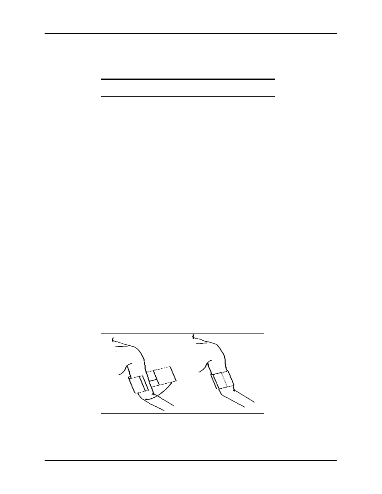
Operations Parameter Menus
The initial default cuff inflation pressure is dependent on the patient size setting as follows:
PATIENT SIZE SETTING DEFAULT CUFF INFLATION PRESSURE
Adult 178 ± 5 mmHg
Pediatric 133 ± 5 mmHg
After the first successful measurement, the subsequent inflation pressure for the same patient
will be 50 ±10 mmHg above the previous systolic pressure measurement.
Upon power ON of the Trio, the NIBP unit of measure defaults to the most recent setting
made in the NIBP SETUP menu.
2.4.4.1 Cuff Application
1. Select a blood pressure cuff that is appropriate for the size of the patient. Measure the
circumference of the patient's limb for the best results.
NOTE: Using a correctly sized cuff, among other considerations,
has a direct bearing on the accuracy of the obtained NIBP
measurements. A cuff that is too narrow for the limb will
result in erroneously high readings. Selection of the cuff size
should be based on the circumference of the patient’s limb.
The design dimensions of the cuffs and their intended use
are based on recommendations made by the American
Heart Association.
NOTE: Use only the authorized blood pressure cuffs and hoses
listed in section 5.0, “Accessories” with the Trio.
2. Attach the NIBP cuff to the NIBP extension hose.
3. Attach the NIBP extension hose to the NIBP pneumatic fitting on the Trio.
4. Apply the cuff to the patient as shown in FIGURE 2-36. To reduce errors, ensure that the
cuff is deflated and lies directly against the patient's skin. The cuff should fit snugly.
There should be no clothing between the patient’s skin and the cuff
CAUTION: The cuff must be properly applied to the patient's limb
before inflating. If it is inflated without being securely
wrapped, damage to the cuff can result.
FIGURE 2-36 Application of the Blood Pressure Cuff
Trio™ Operating Instructions 0070-10-0666-01 2 - 45
Page 75

Parameter Menus Operations
2.4.4.2 Measurement
1. Ensure that the appropriate PATIENT SIZE (Adult or Pediatric) has been selected from
the PATIENT SETUP menu accessible from the SYSTEM MENU.
2. Depending on the desired measurement frequency mode, proceed as follows:
Manual Mode
Press the NIBP key, located on the front panel keypad, to begin the NIBP measurement.
Interval Mode
a. Open the NIBP SETUP menu by selecting NIBP from the main display using the
Navigator™ Knob. Once in the NIBP SETUP menu, select the INTERVAL Drop-
Down menu and choose the desired setting.
b. Press the NIBP key, located on the front panel keypad, to initiate the first
measurement of the interval measurement cycle.
• To initiate a STAT blood pressure at any time between intervals, press the NIBP
key on the front panel keypad.
• To exit the Interval Mode, choose OFF from the INTERVAL Drop-Down menu.
NOTE: If CONT (Continuous) is chosen as the interval, the
monitor will take continuous blood pressure
readings for five (5) minutes. After 5 minutes, the
Trio will automatically revert to an Interval Mode of
5 minutes. The NIBP key on the front panel keypad
must be pressed to initiate the new interval.
The cuff begins to inflate. After reaching the default pressure for the selected patient size, the
cuff gradually deflates and the Trio collects oscillometric pulsations. During this inflation and
deflation portion of the measurement, the current pressure in the cuff is displayed in the lower
right corner of the NIBP parameter tile as “CUFF:XXX”.
If a measurement cannot be obtained, the Trio automatically reinflates the cuff to 30 – 60
mmHg higher than the initial inflation pressure, but will not exceed the maximum cuff
pressure listed in the “NIBP Sub-System Functional Requirements”, section 6.2.6.5.
The patient should remain still to avoid the introduction of unnecessary motion artifact. After
the cuff pressure drops below the diastolic pressure, the measurements are displayed in the
NIBP parameter tile. These results will remain displayed in the NIBP parameter tile until the
user-definable DISPLAY TIMEOUT interval has been reached or until a new NIBP
measurement is obtained. The default DISPLAY TIMEOUT interval is 15 minutes.
NOTE: Pressing the NIBP key while the NIBP measurement is in
progress will stop the measurement and deflate the cuff.
2 - 46 0070-10-0666-01 Trio™ Operating Instructions
Page 76

Operations Parameter Menus
ET:5min
CUFF: 100
NIBP
mmHg
108
70
(84)
Cont measuring...
Interval:OFF
Systolic Value
Mean Value
Status Message
Elapsed Time
(since the last
measurement)
Diastolic Value
Unit of Measure
Current Cuff Pressure
Alarm OFF Symbol
Interval
2.4.4.3 NIBP Display Tile
If ECG and NIBP are selected in the MODULE SETUP menu, NIBP will be displayed in the
second parameter tile, beneath the ECG parameter tile. If ECG is not selected in the
MODULE SETUP menu, NIBP will be displayed in the first parameter tile. The following
data is displayed:
FIGURE 2-37 NIBP Parameter Tile
The following status messages may be displayed during the measurement of NIBP:
MESSAGE CAUSE
Cont measuring… Displayed during Continuous measuring
Auto measuring… Displayed during Automatic / Interval measuring
Please start Displayed after selecting an INTERVAL in the NIBP SETUP
Measurement over Displayed after an NIBP measurement has been manually stopped by
pressing the NIBP key during the measurement.
menu
To Purchase, Visit Avobus.com or call 1-800-674-3655
Trio™ Operating Instructions 0070-10-0666-01 2 - 47
Page 77

Parameter Menus Operations
2.4.4.4 NIBP Setup Menu
FIGURE 2-38 NIBP Setup Menu
Accessing the NIBP Setup Menu
To access the NIBP SETUP menu, select NIBP from the NIBP parameter tile using the
Navigator™ Knob. Once in the NIBP SETUP menu, use the Navigator Knob to adjust
settings. To close the menu, select NORMAL SCREEN (from the menu or the Front Panel
Keypad).
NIBP Setup Menu Selections
ALM Allows the user to turn the NIBP alarm ON or OFF. Choose ON to
enable the alarm; choose OFF to disable the alarm. If the alarm is set
to OFF, the alarm OFF symbol will display to the right of NIBP on
the screen. The NIBP alarm is activated when the blood pressure
value exceeds set high or low NIBP values.
ALM PRIORITY Allows the user to select the priority of the NIBP alarm. Choices are 1,
2 and 3. Priority 1 alarms are considered the most serious.
ALM PRINT Enables or disables automatic printing during a NIBP alarm condition.
Choose ON to enable printing upon NIBP alarm. Choose OFF to
disable printing upon NIBP alarm.
SYS ALM HI Allows the user to set the upper limit of the Systolic NIBP alarm. (See
“NIBP Alarm Limits” on page 2-50.)
SYS ALM LO Allows the user to set the lower limit of the Systolic NIBP alarm. (See
“NIBP Alarm Limits” on page 2-50.)
2 - 48 0070-10-0666-01 Trio™ Operating Instructions
Page 78

Operations Parameter Menus
MEAN ALM HI Allows the user to set the upper limit of the Mean NIBP alarm. (See
“NIBP Alarm Limits” on page 2-50.)
MEAN ALM LO Allows the user to set the lower limit of the Mean NIBP alarm. (See
“NIBP Alarm Limits” on page 2-50.)
DIA ALM HI Allows the user to set the upper limit of the Diastolic NIBP alarm. (See
“NIBP Alarm Limits” on page 2-50.)
DIA ALM LO Allows the user to set the lower limit of the Diastolic NIBP alarm. (See
“NIBP Alarm Limits” on page 2-50.)
UNITS Allows the user to select the unit of measurement for NIBP. The
selections are mmHg or kPa.
INTERVAL Allows the user to select the interval at which NIBP measurement will
automatically initiate. It also allows the user to turn the automatic
measurement OFF. The selections are: CONT (continuous), 1min,
2min, 3min, 4min, 5min, 10min, 15min, 30min, 1HR,
2HRS, 4HRS and OFF.
DISPLAY
TIMEOUT
RESTORE
DEFAULTS
Allows the user to select the interval at which the NIBP measurement
will time-out from the display. The selections are: 15min, 30min,
45min, and 1HR.
NIBP measurement will time-out from the display when the elapsed
time exceeds the chosen interval, except during an NIBP alarm
condition. The time-out will be suspended until the alarm condition is
resolved and will then resume. When the time-out interval has been
exceeded, the NIBP measurement is replaced by dashes.
Allows the user to restore the NIBP user default configuration.
FIGURE 2-39 Confirmation Dialog Box
Trio™ Operating Instructions 0070-10-0666-01 2 - 49
Page 79

Parameter Menus Operations
*
NIBP Alarm Limits
SYS
PATIENT SIZE
Adult (ADU) 70 – 240
Pediatric (PED) 40 – 180
* Factory default values shown in brackets.
HIGH
(mmHg)
[180]
[150]
SYS
LOW
(mmHg)
50 – 150
[80]
15 – 130
[70]
MEAN
HIGH
(mmHg)
60 – 200
[100]
50 – 180
[80]
MEAN
LOW
(mmHg)
40 – 140
[40]
10 – 100
[30]
DIA
HIGH
(mmHg)
40 – 130
[100]
50 – 100
[80]
DIA
LOW
(mmHg)
30 – 120
[50]
10 – 50
[40]
Alarms occurring during the process of NIBP measurement include two (2) types:
physiological alarms and technical alarms. Physiological alarms occur when the patient’s
pressure values are equal to or exceed set alarm limits. Technical alarms are any NIBPrelated alarms, which are not physiological, such as functional failures.
Indirect BP Measurements and Associated Errors
Place the patient in a supine position to obtain true physiological pressure. If the cuff is not at
the patient's heart level, the pressure values obtained will not reflect the true physiological
pressure. Instead, the readings will be decreased by 0.75 mmHg (0.10 kPa) for every inch
above heart level, and increased by 0.75 mmHg (0.10 kPa) for every inch below heart level.
This is due to changes in hydrostatic pressure.
Precautions While Making Automatically Cycled Blood Pressure
Measurements
Reports have been made of nerve injury occurring from automatically cycled blood pressure
measurements. The following practices are recommended when making automatically cycled
blood pressure measurements:
• Position and support the limb in such a way as to minimize stretching of affected nerves,
as well as, weight exertion on affected nerves
• Avoid cuff placement that applies pressure on the ulnar nerve. Cuff tubing should not exit
the cuff over the course of the ulnar nerve at the elbow
• Select a measurement interval that provides adequate venous drainage during cuff
deflation
• Periodically inspect the limb bearing the cuff in order to detect venostasis
• If necessary, move cuff to another limb to relieve single-limb stress
Cuff Size
When applying the NIBP cuffs use the range markings as a guide to ensure proper fit and
cuff size. Use of a narrow cuff may give erroneous pressure readings. If a standard cuff is
applied to an obese patient or a patient with large biceps, the excess tissue will dissipate the
applied pressure, requiring additional attempts to collapse the artery. This may result in high
pressure readings. Over-wrapping a slender arm may also give erroneous pressure readings
due to excessive force exerted on the arm.
2 - 50 0070-10-0666-01 Trio™ Operating Instructions
To Purchase, Visit Avobus.com or call 1-800-674-3655
Page 80

Operations Parameter Menus
Other Factors
An accurate determination of blood pressure can be difficult to obtain if a patient's cardiac
rhythm is irregular. Irregular cardiac rhythm changes the stroke volume from beat to beat.
This changing stroke volume may increase the time it takes to complete a measurement cycle.
Newborn NIBP Technique
Newborn patients present unique obstacles to NIBP measurement. Their vital signs can
change frequently and their physiological signals are prone to noise interference. The
following suggestions will help to obtain the best possible NIBP measurement.
1. Try to measure infants when they are calm. A kicking/crying baby may disturb or
dislodge the cuff causing noise within the system and as a result, yielding unstable blood
pressure readings. If necessary, hold the cuffed limb steady, but do not impede
circulation; do not hold onto the cuff and do not pat the cuffed limb to comfort the child.
2. Try placement on the baby's calf. Irritable newborns will react to cuff pressure on the
arm, but may better tolerate placement on the calf. Place the cuff just above the ankle.
3. Use the correct size Newborn and Infant size cuffs. When applying, verify the cuff’s
Index line falls between the Range lines.
4. Use disposable cuffs. Disposable cuffs are more pliant than the reusable ones. They
generally fit smaller infants better.
5. Gently place the cuff on the patient. If the cuff is too snug, it won't work properly. On
infants, the cuff should easily move over the limb.
Trio™ Operating Instructions 0070-10-0666-01 2 - 51
Page 81

Parameter Menus Operations
2.4.4.5 NIBP Troubleshooting
MESSAGE/
PROBLEM REASON SOLUTION
NS ALM LMT ERR Functional failure Notify hospital technician or
Customer Support
NM ALM LMT ERR Functional failure Notify hospital technician or
Customer Support
ND ALM LMT ERR Functional failure Notify hospital technician or
Customer Support
NIBP SELF TEST ERR NIBP module hardware failure Notify hospital technician or
Customer Support
NIBP COMM ERR Communication with NIBP module has
failed
LOOSE CUFF Cuff is not properly wrapped or no
cuff exists
AIR LEAK Cuff, hose or connector is damaged Check cuff and hose connections,
Internal Leak
AIR PRESSURE
ERROR
WEAK SIGNAL Cuff is too loose or patient pulse is too
RANGE EXCEEDED NIBP value exceeds the upper
EXCESSIVE
MOTION and/or
SIGNAL
SATURATED
OVER PRESSURE Pressure has exceeded the specified
PNEUMATIC LEAK During pneumatic test, leak is
NIBP SYSTEM
FAI LURE
NIBP TIME OUT Measuring time has exceeded 120
MEASURE FAIL The system cannot perform
Unable to obtain a
BP reading
Stable pressure value is not available.
e.g. hoses are pinched or occluded
weak
measurement limit
Monitor is detecting too much motion
and/or noise to obtain a reading
upper safety limit
detected
Operation of blood pressure pump
system failed
seconds
measurement, analysis or calculation
Patient movement Wait until patient is calm or gently
Cuff or hose not attached or leaking Check all connections
HR irregular / arrhythmia present Check patient, notify physician
Blood pressure is out of range Check patient, verify BP with
Incorrect cuff size / brand Measure patient’s limb, verify cuff
Notify hospital technician or
Customer Support
Check cuff, reapply if necessary
replace as necessary. If problem
persists, notify hospital technician
or Customer Support.
Check hoses. If failure persists,
notify hospital technician or
Customer Support.
Check patient, reapply hose. Notify
physician.
Check patient, notify physician
Instruct patient to remain still during
the NIBP cuff reading. If patient is
agitated, consider trying to take the
pressure at a later time when
patient is calm.
Try again. If failure persists, notify
hospital technician or Customer
Support.
Notify hospital technician or
Customer Support
Notify hospital technician or
Customer Support
Check patient, restart NIBP
measurement
Check patient, restart NIBP
measurement
hold patient’s limb
manual method, notify physician
size. Use only approved
accessories.
2 - 52 0070-10-0666-01 Trio™ Operating Instructions
Page 82

Operations Parameter Menus
2.4.5 Temperature Monitoring
The temperature (TEMP) measurement function of the Trio is designed to take continuous
temperature readings from the YSI 400 series probes. One (1) temperature channel is
standard on the Trio.
1. If using a disposable temperature probe:
Connect the preferred disposable temperature probe into the reusable temperature
cable. Plug the cable into the monitor.
2. If using a reusable temperature probe:
Plug the reusable probe directly into the monitor
3. Follow probe manufacturer's suggested temperature monitoring sites and suggested
procedures for site checks, reapplication and moving of the probes.
4. Check the probe site frequently for position, ensuring good contact with the site chosen.
For example, check the skin probe frequently to ensure good skin contact.
NOTE: A self-test of the temperature measurement is performed
automatically once per hour during the monitoring period.
The test procedure lasts approximately 2 seconds and does
not affect the normal measurement of the temperature
monitoring.
2.4.5.1 Temperature Setup
FIGURE 2-40 Temperature Setup Menu
Accessing the Temperature Setup Menu
To access the TEMP SETUP menu, select TEMP from the TEMP parameter tile using the
Navigator™ Knob. Once in the TEMP SETUP menu, use the Navigator Knob to adjust
settings. To close the menu, select NORMAL SCREEN (from the menu or the Front Panel
Keypad).
Trio™ Operating Instructions 0070-10-0666-01 2 - 53
To Purchase, Visit Avobus.com or call 1-800-674-3655
Page 83

Parameter Menus Operations
*
Temperature Setup Menu Selections
ALM Allows the user to turn the TEMP alarm ON or OFF. Choose ON to
enable the alarm; choose OFF to disable the alarm. If the alarm is set
to OFF, the alarm OFF symbol will display to the right of TEMP
on the screen. The TEMP alarm is activated when the temperature
value exceeds set high or low TEMP values.
ALM PRIORITY Enables priority selection for the TEMP alarm. Choices are 1, 2 and
3. Priority 1 alarms are considered the most serious.
ALM PRINT Enables or disables automatic printing during a TEMP alarm
condition. Choose ON to enable printing upon TEMP alarm. Choose
OFF to disable printing upon TEMP alarm.
TEMP ALM HI Allows the user to set the upper limit of Temperature 1 alarm. (See
“Temperature Alarm Limits” on page 2-54.)
TEMP ALM LO Allows the user to set the lower limit of Temperature 1 alarm. (See
“Temperature Alarm Limits” on page 2-54.)
TEMP UNIT Allows the user to select the unit of measure for temperature. The
selections are degrees Celsius (°C) or degrees Fahrenheit (°F).
RESTORE
DEFAULTS
Allows the user to restore the TEMP user default configuration.
FIGURE 2-41 Confirmation Dialog Box
Temperature Alarm Limits
HIGH
ALARM (ºC)
Temperature (T1) 35 – 43 [40] 26 – 38 [30] 95 – 109.4 [104] 78.8 – 100.4 [86]
* Factory default values shown in brackets.
LOW
ALARM (ºC)
HIGH
ALARM (ºF)
LOW
ALARM (ºF)
Alarms occurring during the process of temperature measurement include two (2) types:
physiological alarms and technical alarms. Physiological alarms occur when the patient’s
temperature values are equal to or exceed set alarm limits. Technical alarms are any
temperature-related alarms, which are not physiological, such as functional failures.
2 - 54 0070-10-0666-01 Trio™ Operating Instructions
Page 84

Operations Parameter Menus
2.4.5.2 Temperature Troubleshooting
MESSAGE/
PROBLEM REASON SOLUTION
T1 SENSOR OFF Temperature cable of channel 1 may
be disconnected from the monitor
TEMP SENSOR
OFF
T1 ALM LMT ERR Functional failure Notify hospital technician or
TEMP ALM LMT ERR Functional failure Notify hospital technician or
T1 EXCEED Temperature value of channel exceeds
TEMP EXCEED Temperature value of channel exceeds
Temperature Probes
not working
Temperature not
displayed
Temperature cable of channel 1 may
be disconnected from the monitor
measurement range
measurement range
Poor contact from probes to body Check the body surface contact at
Cable not plugged in Check cable and probe
Make sure that the temperature
cable is properly connected, check
connection between probe and
cable
Make sure that the temperature
cable is properly connected, check
connection between probe and
cable
Customer Support
Customer Support
Check patient, notify physician
Check patient, notify physician
the probe tip
Reposition or apply
thermoconductive gel
Trio™ Operating Instructions 0070-10-0666-01 2 - 55
Page 85

Parameter Menus Operations
2.4.6 IBP Monitoring (Optional)
Invasive Blood Pressure (IBP) is a direct measurement of the patient's arterial or venous blood
pressure. IBP utilizes a catheter that is inserted directly into a vein or artery and is connected
to a transducer for interpretation of Systolic (Sys), Diastolic (Dia) and/or Mean Arterial
Pressures (MAP).
The user may label the IBP channel according to the insertion site of the catheter or according
to the vessel being monitored. To do this select the IBP label, located in the upper left corner
of the IBP waveform tile, using the Navigator™ Knob. The labels are: ART, PA, CVP, RAP,
LAP and ICP. The selection of IBP labels will alter the IBP waveform default scale.
LABEL DEFINITION DEFAULT SCALE (mmHg)
ART Arterial Blood Pressure 0 – 150
PA Pulmonary Artery Pressure 0 – 100
CVP Central Venous Pressure 0 – 40
RAP Right Atrial Pressure 0 – 40
LAP Left Atrial Pressure 0 – 40
ICP Intracranial Pressure 0 – 40
N O T E : Fo r C V P, RA P, L AP an d I C P on ly the Mean Arterial Pressure is
measured.
NOTE: An arterial pressure catheter should not be used on a limb
that is being utilized for any other medical procedure. For
example, an IV catheter, NIBP measurement or SpO
readings.
NOTE: Please refer to pressure transducer manufacturer's
instructions for suggested procedures and maintenance.
Follow hospital policy regarding catheter insertion, insertion
site checks and cleaning.
NOTE: Pressure transducers are protected against the effects of
defibrillation and electrocautery.
NOTE: Please refer to the local hospital policy for requirements for
routine zeroing and calibration of invasive pressure lines.
2
2 - 56 0070-10-0666-01 Trio™ Operating Instructions
To Purchase, Visit Avobus.com or call 1-800-674-3655
Page 86

Operations Parameter Menus
2.4.6.1 IBP Select Menu
The IBP Select menu allows the user to access two sub-menus: IBP ZERO or IBP SETUP
(see FIGURE 2-42).
FIGURE 2-42 IBP Select Menu
Accessing the IBP Select Menu
To access the IBP SELECT menu, select IBP from the IBP parameter tile using the
Navigator™ Knob. Once in the IBP SELECT menu, use the Navigator Knob to open the IBP
ZERO menu (to zero the invasive pressure) or IBP SETUP menu. To close the menu, select
NORMAL SCREEN (from the menu or the Front Panel Keypad).
Invasive Blood Pressure Monitoring
1. Plug the pressure transducer cable into the IBP connector on the side panel.
2. Connect the catheter line with flushing device to a pressure transducer, making sure the
tubing is free of air bubbles.
3. Zero the pressure transducer:
• Adjust the transducer to the mid-axillary line of the patient's chest (heart level)
• Turn the transducer stopcock to open the transducer vent to atmosphere
•Open the IBP SELECT menu by using the Navigator™ Knob to select IBP on the
display
•Select IBP ZERO from the IBP SELECT menu
• Once in the IBP ZERO menu, select IBP ZERO to zero the invasive line
• A successful message will be displayed in the IBP ZERO menu when the invasive line
has been zeroed successfully
• A failure message will be displayed if the transducer fails to zero
Trio™ Operating Instructions 0070-10-0666-01 2 - 57
Page 87

Parameter Menus Operations
FIGURE 2-43 IBP Zero Menu
4. Label the Invasive Pressure line
• Use the Navigator™ Knob to select the IBP label located in the upper left corner of the
IBP waveform tile
• Turn the Navigator Knob to scroll through the various labels. Choices are: ART, PA,
CVP, RAP, LAP, and ICP
• Press the Navigator Knob to select the desired label
2.4.6.2 IBP Setup Menu
FIGURE 2-44 IBP Setup Menu
Accessing the IBP Setup Menu
To access the IBP SELECT menu, select IBP from the IBP parameter tile using the
Navigator™ Knob. Once in the IBP SELECT menu, use the Navigator Knob to open the IBP
SETUP menu. To close the menu, select NORMAL SCREEN (from the menu or the Front
Panel Keypad).
2 - 58 0070-10-0666-01 Trio™ Operating Instructions
Page 88

Operations Parameter Menus
IBP Setup Menu Selections
ALM Allows the user to turn the IBP alarm ON or OFF. Choose ON to
enable the alarm; choose OFF to disable the alarm. If the alarm is set
to OFF, the alarm OFF symbol will display to the right of IBP on
the screen. The IBP alarm is activated when the blood pressure value
exceeds set high or low IBP values.
ALM PRIORITY Enables priority selection for the IBP alarm. Choices are 1, 2 and 3.
Priority 1 alarms are considered the most serious.
ALM PRINT Enables or disables automatic printing during an IBP alarm condition.
Choose ON to enable report printing upon IBP alarm. Choose OFF
to disable printing upon IBP alarm.
SYS ALM HI Allows the user to set the upper limit of the Systolic IBP alarm.
(See “IBP Alarm Limits” on page 2-61.)
SYS ALM LO Allows the user to set the lower limit of the Systolic IBP alarm.
(See “IBP Alarm Limits” on page 2-61.)
MEAN ALM HI Allows the user to set the upper limit of the Mean Arterial Pressure IBP
alarm. (See “IBP Alarm Limits” on page 2-61.)
MEAN ALM LO Allows the user to set the lower limit of the Mean Arterial Pressure IBP
alarm. (See “IBP Alarm Limits” on page 2-61.)
DIA ALM HI Allows the user to set the upper limit of the Diastolic IBP alarm.
(See “IBP Alarm Limits” on page 2-61.)
DIA ALM LO Allows the user to set the lower limit of the Diastolic IBP alarm.
(See “IBP Alarm Limits” on page 2-61.)
SWEEP Adjusts the speed of the IBP waveform on the display. The selections
are 12.5 and 25.0 mm/sec.
UNITS Allows the user to select the units of measurement for IBP. The
selections are mmHg or kPa.
Trio™ Operating Instructions 0070-10-0666-01 2 - 59
To Purchase, Visit Avobus.com or call 1-800-674-3655
Page 89

Parameter Menus Operations
SCALE ADJUST Opens the IBP SCALE ADJUST menu and is used to change the
scale at which the invasive pressure is displayed. Scale should be
adjusted to make the waveform as large as possible on the display
without clipping or cutting off any part.
To adjust the scale, use the Navigator™ Knob to scroll to the desired
area of the scale and select the desired limit. Three (3) scale choices
are available: HI, LO and MID. MID allows the user to establish a
reference line between the HI and LO set limits of the scale.
RESTORE
DEFAULTS
FIGURE 2-45 IBP Scale Adjust Menu
Allows the user to restore the IBP user default configuration.
FIGURE 2-46 Confirmation Dialog Box
2 - 60 0070-10-0666-01 Trio™ Operating Instructions
Page 90

Operations Parameter Menus
*
IBP Alarm Limits
IBP
LABEL
Adult
ART
Ped
Adult
PA
Ped
Adult
CVP
Ped
Adult
RAP
Ped
Adult
LAP
Ped
Adult
ICP
Ped
* Factory default values shown in brackets.
SYS
HIGH
(mmHg)
5 – 300
[180]
5 – 240
[150]
5 – 300
[180]
5 – 240
[150]
n/a n/a 5 – 150
n/a n/a 5 – 100
n/a n/a 5 – 150
n/a n/a 5 – 100
n/a n/a 5 – 150
n
/a n/a 5 – 100
n/a n/a 5 – 150
n/a n/a 5 – 100
SYS
LOW
(mmHg)
0 – 150
[80]
0 – 130
[70]
0 – 150
[80]
0 – 130
[70]
MEAN
HIGH
(mmHg)
5 – 150
[100]
5 – 100
[80]
5 – 150
[100]
5 – 100
[80]
[10]
[10]
[10]
[10]
[10]
[10]
[10]
[10]
MEAN
LOW
(mmHg)
- 5 – 100
[40]
- 5 – 50
[30]
- 5 – 100
[40]
- 5 – 50
[30]
- 5 – 100
[0]
- 5 – 50
[0]
- 5 – 100
[0]
- 5 – 50
[0]
- 5 – 100
[0]
- 5 – 50
[0]
- 5 – 100
[0]
- 5 – 50
[0]
DIA
HIGH
(mmHg)
5 – 140
[100]
5 – 100
[80]
5 – 140
[100]
5 – 100
[80]
n/a n/a
n/a n/a
n/a n/a
n/a n/a
n/a n/a
n/a n/a
n/a n/a
n/a n/a
DIA
LOW
(mmHg)
0 – 120
[50]
0 – 95
[40]
0 – 120
[50]
0 – 98
[40]
Alarms occurring during the process of IBP measurement include two (2) types: physiological
alarms and technical alarms. Physiological alarms occur when the patient’s pressure values
are equal to or exceed set alarm limits. Technical alarms are any IBP-related alarms, which
are not physiological, such as functional failures.
Trio™ Operating Instructions 0070-10-0666-01 2 - 61
Page 91

Parameter Menus Operations
2.4.6.3 IBP Troubleshooting
MESSAGE/
PROBLEM REASON SOLUTION
SENSOR OFF, FAIL Transducer may be disconnected
during attempt to zero
IN DEMO FAIL Monitor is in DEMO mode during
PRESSURE OVER
RANGE, FAIL
PULSATILE
PRESSURE, FAIL
IBP SENSOR OFF IBP cable may be disconnected from
IBP INIT ERR1 Module failure Notify hospital technician or
IBP COMM STOP Module failure or communication
IBP COMM ERR Communication error Notify hospital technician or
IBP ALM LMT ERR Functional failure Notify hospital technician or
IBP SYS EXCEED Systolic pressure value exceeds
IBP DIA EXCEED Diastolic pressure value exceeds
IBP MAP EXCEED Mean arterial pressure value exceeds
IBP NEED ZEROCAL
Dampened Invasive
Wav efo rm
IBP not Displayed /
No Waveform
Abnormally high or
low readings
attempt to zero
Stopcock not open to atmosphere Turn stopcock to atmosphere prior
Stopcock is not open to atmosphere
and a pulsatile pressure has been
detected
monitor
failure
measurement range
measurement range
measurement range
Zero calibration must be performed
before measuring IBP
Air bubbles in tubing Eliminate air from tubing
Kinked invasive catheter Change position of catheter, check
Catheter against wall of blood vessel Check for leaks at connector, flush
Blood in tubing Pump pressure bag up to
Catheter partially occluded Consult physician
Cable not plugged in Check cable connections
Transducer not connected Check transducer connections
Stopcock turned improperly Check transducer for proper
Transducer not zeroed Check and zero the transducer
Transducer too HIGH or too LOW in
relation to patient's heart
Check transducer and cables for
connection. If problem persists,
notify hospital technician or
Customer Support
Turn monitor OFF. Turn ON to
return to normal monitoring mode
to zero attempt. If problem persists,
notify hospital technician or
Customer Support
Turn stopcock to atmosphere prior
to zero attempt. If problem persists,
notify hospital technician or
Customer Support
Make sure that cable is properly
connected
Customer Support
Notify hospital technician or
Customer Support
Customer Support
Customer Support
Check patient, notify physician
Check patient, notify physician
Check patient, notify physician
Zero calibration must be
performed. Notify hospital
technician or Customer Support.
patient
catheter
300 mmHg
alignment
Check patient, adjust transducer,
re-zero
2 - 62 0070-10-0666-01 Trio™ Operating Instructions
To Purchase, Visit Avobus.com or call 1-800-674-3655
Page 92

Operations Alarms
2.5 Alarms
The Trio provides audio and visual alarms to indicate:
• The functional status of the monitor
• That the measured parameter values are equal to or exceed the alarm limits
These alarms are divided into three categories: Physiological, Technical and General. Alarms
in each category are classified in one of three levels based on their degree of severity. These
levels are Priority 1, 2 or 3.
When the Trio is turned ON, an audible tone and the alarm light will indicate that the audio
and visual alarm functions of the monitor are working properly. If the tone is not heard and/
or the alarm light does not flash when the unit is turned ON, contact the hospital biomedical
technician or a Customer Service representative.
Technical and General alarm messages will display in the message area located in the upper
right portion of the Trio display, with the exception of the NIBP technical alarms. NIBP
technical alarms will display at the bottom of the NIBP parameter tile.
2.5.1 Alarm Categories
Physiological Alarms
Physiological alarms are alarms prompted by changes in the patient's medical condition.
These alarms occur when the patient’s vital signs are equal to or exceed set alarm limits.
Alarm limits are available for Heart Rate (HR), Systolic (SYS) blood pressure, Diastolic (DIA)
blood pressure, Mean Arterial Pressure (MEAN), Respiration (RESP), SpO
(TEMP). All of these alarm limits have an OFF selection with the exception of SpO
low. Each of these parameters has default alarm limits. However, parameter alarm limits can
be customized based on the individual patient's needs.
NOTE: In the French configuration, the HR (Heart Rate) alarm is
always ON. It cannot be disabled by turning it OFF.
A physiological alarm will occur when the parameter alarm is set to ON and the measured value
is equal to or exceeds the set alarm limit. Alarms will not activate if the alarm is set to
If ALARM PRINT is set to ON for a given parameter, a printed record will automatically be
generated when the parameter value is equal to or exceeds the set alarm limits.
Technical Alarms
Technical alarms refer to a communication error or functional failure, which require resolution
or attention to continue patient monitoring. Technical alarms are also called System Errors.
and Temperature
2
alarm
2
OFF
.
Upon detecting a system error, the monitor alarms immediately. If more than one (1) technical
alarm occurs, each alarm will cycle until the associated error is resolved.
Trio™ Operating Instructions 0070-10-0666-01 2 - 63
Page 93

Alarms Operations
General Alarms
General alarms are alerts that cannot be classified as physiological or technical, but that
require attention. General alarms are not related to patient medical condition.
2.5.2 Alarm Priorities
Alarms in each category (Physiological, Technical or General) are classified based on their
degree of severity. The priority determines the frequency of audio and visual alerts. There are
two (2) visual alerts: the alarm light and the alarm-related message on the display. For an
ECG Lead Off alarm, the alarm will sound according to the ECG priority setting.
1. Priority One (1) Alarm: This alarm requires an urgent and immediate response from
the clinician. The numeric value of the alarming parameter will flash at a constant rate in
black text on a red background. The alarm light will flash red with high frequency. The
audio alert cycles once every ten (10) seconds.
2. Priority Two (2) Alarm: This alarm requires a serious response and consideration by
the clinician. The numeric value of the alarming parameter will flash at a constant rate in
black text on a yellow background. The alarm light flashes amber with a slow frequency.
The audio alert cycles once every 25 seconds.
3. Priority Three (3) Alarm: This alert should be attended to as soon as possible by the
clinician. The numeric value of the alarming parameter displays in black text on a yellow
background and does not flash. The alarm light will be amber and does not flash. The
audio alert cycles once every 25 seconds.
All physiological alarms can be changed by the clinician. Technical alarm priorities are
preset in the system and can not be changed. The alert message for technical alarms displays
on a yellow background. To change the parameter alarm priorities, open the individual
PARAMETER SETUP menus and select the priority desired. Parameter alarm priorities may
also be adjusted in the ALARM SETUP menu.
NOTE: When alarms of different priorities occur simultaneously, the
monitor will display the alarm with the highest priority.
2.5.3 Alarm Setup Menus
The Alarm Setup Menus enable the customization of the COMMON ALARM SETUP as
well as the ALARM SETUPs for the following individual parameters: HR, SPO2, NIBP,
IBP, RESP, and TEMP.
2.5.3.1 Accessing the Alarm Setup Menus
1. Using the Navigator™ Knob, select ALARM SETUP from the MONITOR SETUP
menu. The default ALARM SETUP menu is the COMMON ALARM SETUP as shown
in FIGURE 2-47.
2. Use the ALM SEL Drop-Down menu to access the ALARM SETUP menu for a specific
parameter. The choices are: HR ALARM SETUP, SPO2 ALARM SETUP, NIBP
ALARM SETUP, IBP ALARM SETUP, RESP ALARM SETUP, and TEMP ALARM
SETUP. The selected ALARM SETUP menu will determine the other available menu
selections.
NOTE: For more information on parameter alarms and instructions
for setting these alarms, refer to the parameter-specific
section of this Operator's Manual.
2 - 64 0070-10-0666-01 Trio™ Operating Instructions
Page 94

Operations Alarms
COMMON ALARM SETUP Menu Selections
FIGURE 2-47 Common Alarm Setup Menu
ALM SEL
(Alarm Selection)
Choose COMMON ALARM SETUP.
ALARM VOL Volume of the audio alert. Selections are: LOW, MED, and HIGH.
ALM PRINT TIME Length of the printed waveform. Selections are: 8s, 16s, or 32s.
ALM MUTE TIME Length of time for the alarm to be silenced. Selections are:1min,
2min, 5min, 10min, and PERMANENT.
When ALM MUTE TIME is set to PERMANENT and Alarm Mute
is active, the message “Alarms Permanently Muted” displays at a
constant rate in the technical alarms area.
• If another technical alarm occurs at the same time, both
messages will display alternately.
•If the ALM MUTE TIME is changed to something other than
PERMANENT, the following conditions will exist:
• The elapsed time is defined as the time from which ALM
MUTE TIME had been set to PERMANENT to the time at
which it was changed to something other than
PERMANENT.
• If the elapsed time exceeds the newly selected ALM MUTE
TIME, then the Alarm Mute will immediately deactivate.
Example: Elapsed time = 5min, New ALM MUTE TIME =
2min, Alarm Mute immediately deactivates.
• If the elapsed time is less than the newly selected ALM
MUTE TIME, then the Alarm Mute will continue to be active
for the remainder of the newly selected time period.
Example: Elapsed time = 2min, New ALM MUTE TIME =
10min, Alarm Mute continues to be active for 8 minutes and
then deactivates.
Trio™ Operating Instructions 0070-10-0666-01 2 - 65
To Purchase, Visit Avobus.com or call 1-800-674-3655
Page 95

Alarms Operations
HR ALARM SETUP Menu Selections
FIGURE 2-48 HR Alarm Setup Menu
ALM SEL
Choose HR ALARM SETUP.
(Alarm Selection)
ALM
NOTE: In the French configuration, the HR
(Heart Rate) alarm is always ON. It
cannot be disabled by turning it
OFF.
Allows the user to turn the HR (Heart Rate) alarm ON or OFF.
Choose ON to enable the alarm; choose OFF to disable the
alarm. If the alarm is set to OFF, the alarm OFF symbol will
display to the right of ECG on the screen. The HR alarm is
activated when the heart rate is equal to or exceeds set high or
low HR values.
ALM PRIORITY Allows the user to select the priority of the alarm. Choices are 1,
2 and 3. Priority 1 alarms are considered the most serious.
ALM PRINT Allows the user to enable or disable automatic printing during a
physiological alarm condition. Choose ON to enable printing
upon alarm. Choose OFF to disable printing upon alarm. See
“Recorder (Optional)” on page 2-82 for details.
HR ALM HI Allows the user to set the upper limit of the HR alarm. (See “Heart
Rate Alarm Limits” on page 2-27.)
HR ALM LO Allows the user to set the lower limit of the HR alarm. (See “Heart
Rate Alarm Limits” on page 2-27.)
2 - 66 0070-10-0666-01 Trio™ Operating Instructions
Page 96

Operations Alarms
SPO2 ALARM SETUP Menu Selections
FIGURE 2-49 SPO2 Alarm Setup Menu (Masimo® only)
FIGURE 2-50 SPO2 Alarm Setup Menu (Nellcor® only)
NOTE: See the appropriate subsection of the “SpO2 Monitoring”
ALM SEL
(Alarm Selection)
ALM PRIORITY Allows the user to select the priority of the alarm. Choices are 1,
Trio™ Operating Instructions 0070-10-0666-01 2 - 67
section for the alarm limits
Choose SPO2 ALARM SETUP.
2 and 3. Priority 1 alarms are considered the most serious.
Page 97

Alarms Operations
ALM PRINT Allows the user to enable or disable automatic printing during a
physiological alarm condition. Choose ON to enable printing
upon alarm. Choose OFF to disable printing upon alarm. See
“Recorder (Optional)” on page 2-82 for details.
SPO2 ALM HI Allows the user to set the upper limit of the SPO2 alarm. Choices
are 80 – 100% and OFF. Choose OFF to disable the alarm. If the
alarm is set to OFF, the alarm OFF symbol will display within
the parameter tile. The alarm is activated when the measurement
equals or exceeds the high limit.
SPO2 ALM LO Allows the user to set the lower limit of SPO2 alarm.
PR ALM HI Allows the user to set the upper limit of the Pulse Rate alarm.
PR ALM LO Allows the user to set the lower limit of the Pulse Rate alarm.
SENSOR OFF
AUDIO
SAT SECONDS
(Nellcor® only)
Controls the onset of the audio beep alarm for the “SpO2 Sensor
OFF” condition. The choices are ON and OFF.
If ON is selected, then the audio beep alarm will sound when an
“SpO2 Sensor OFF” condition occurs. If OFF is selected, then the
audio beep alarm will not sound when an “SpO2 Sensor OFF”
condition occurs.
Controls pulse oximetry nuisance alarms (see section 2.4.3.2 for
details on SatSeconds™ features). The selections are OFF, 10,
25, 50 or 100.
When SatSeconds is enabled, the SPO2 Low and High Alarm
functions are automatically disabled. As a safety precaution, if
three (3) SPO2 alarm violations occur within 60 seconds, a
priority 2 alarm will trigger even if the SatSeconds limit has not
been reached.
2 - 68 0070-10-0666-01 Trio™ Operating Instructions
To Purchase, Visit Avobus.com or call 1-800-674-3655
Page 98

Operations Alarms
NIBP ALARM SETUP Menu Selections
FIGURE 2-51 NIBP Alarm Setup Menu
ALM SEL
(Alarm Selection)
ALM Allows the user to turn the alarm ON or OFF. Choose ON to
ALM PRIORITY Allows the user to select the priority of the alarm. Choices are 1,
ALM PRINT Allows the user to enable or disable automatic printing during a
SYS ALM HI Allows the user to set the upper limit of the Systolic NIBP alarm.
Choose NIBP ALARM SETUP.
enable the alarm; choose OFF to disable the alarm. If the alarm is
set to OFF, the alarm OFF symbol will display within the
parameter tile. The alarm is activated when the measurement
exceeds the high or low limits.
2 and 3. Priority 1 alarms are considered the most serious.
physiological alarm condition. Choose ON to enable printing
upon alarm. Choose OFF to disable printing upon alarm. See
“Recorder (Optional)” on page 2-82 for details.
(See “NIBP Alarm Limits” on page 2-50.)
SYS ALM LO Allows the user to set the lower limit of the Systolic NIBP alarm.
(See “NIBP Alarm Limits” on page 2-50.)
MEAN ALM HI Allows the user to set the upper limit of the Mean NIBP alarm.
(See “NIBP Alarm Limits” on page 2-50.)
Trio™ Operating Instructions 0070-10-0666-01 2 - 69
Page 99

Alarms Operations
MEAN ALM LO Allows the user to set the lower limit of the Mean NIBP alarm.
(See “NIBP Alarm Limits” on page 2-50.)
DIA ALM HI Allows the user to set the upper limit of the Diastolic NIBP alarm.
(See “NIBP Alarm Limits” on page 2-50.)
DIA ALM LO Allows the user to set the lower limit of the Diastolic NIBP alarm.
(See “NIBP Alarm Limits” on page 2-50.)
2 - 70 0070-10-0666-01 Trio™ Operating Instructions
Page 100

Operations Alarms
IBP ALARM SETUP Menu Selections
FIGURE 2-52 IBP Alarm Setup Menu
ALM SEL
(Alarm Selection)
ALM Allows the user to turn the alarm ON or OFF. Choose ON to
ALM PRIORITY Allows the user to select the priority of the alarm. Choices are 1,
ALM PRINT Allows the user to enable or disable automatic printing during a
SYS ALM HI Allows the user to set the upper limit of the Systolic IBP alarm.
Choose IBP ALARM SETUP.
enable the alarm; choose OFF to disable the alarm. If the alarm is
set to OFF, the alarm OFF symbol will display within the
parameter tile. The alarm is activated when the measurement
exceeds the high or low limits.
2 and 3. Priority 1 alarms are considered the most serious.
physiological alarm condition. Choose ON to enable printing
upon alarm. Choose OFF to disable printing upon alarm. See
“Recorder (Optional)” on page 2-82 for details.
(See “IBP Alarm Limits” on page 2-61.)
SYS ALM LO Allows the user to set the lower limit of the Systolic IBP alarm.
(See “IBP Alarm Limits” on page 2-61.)
MEAN ALM HI Allows the user to set the upper limit of the Mean IBP alarm.
(See “IBP Alarm Limits” on page 2-61.)
Trio™ Operating Instructions 0070-10-0666-01 2 - 71
To Purchase, Visit Avobus.com or call 1-800-674-3655
 Loading...