

Page 1

TE7/TE5
Diagnostic Ultrasound System
Operator’s Manual
[Basic Volume]
Page 2

Page 3

Contents
Contents ............................................................................................................................... i
Intellectual Property Statement .......................................................................................................... I
Responsibility on the Manufacturer Party .......................................................................................... I
Warranty ............................................................................................................................................ II
Exemptions ................................................................................................................................... II
Customer Service Department ..................................................................................................... II
Important Information ....................................................................................................................... III
About This Manual ........................................................................................................................... III
Notation Conventions ....................................................................................................................... IV
Operator’s Manuals .......................................................................................................................... IV
Hardcopy Manuals ........................................................................................................................... IV
Software Interfaces in this Manual ................................................................................................... IV
Conventions ...................................................................................................................................... V
Product Differences ........................................................................................................................... V
1 Safety Precautions .................................................................................................... 1-1
1.1 Safety Classifications ........................................................................................................... 1-1
1.2 Meanings of Signal Words ................................................................................................... 1-2
1.3 Meaning of Safety Symbols ................................................................................................. 1-2
1.4 Safety Precautions ............................................................................................................... 1-3
1.5 Latex Alert .......................................................................................................................... 1-10
1.6 Warning Labels .................................................................................................................. 1-11
2 System Overview ...................................................................................................... 2-1
2.1 Intended Use ........................................................................................................................ 2-1
2.2 Product Specifications .......................................................................................................... 2-1
2.3 System Configuration ........................................................................................................... 2-2
2.4 Introduction of Each Unit ...................................................................................................... 2-8
2.5 Symbols .............................................................................................................................. 2-10
3 System Preparation .................................................................................................. 3-1
3.1 Move/Position the System .................................................................................................... 3-1
3.2 Power ON/OFF ..................................................................................................................... 3-2
3.3 Connecting the Power Cord ................................................................................................. 3-5
3.4 Connecting a Probe ............................................................................................................. 3-6
3.5 Connecting the Footswitch ................................................................................................... 3-7
3.6 Connecting USB Devices ..................................................................................................... 3-7
3.7 Installing a Graph/Text Printer .............................................................................................. 3-8
3.8 Installing a Video Printer .................................................................................................... 3-10
3.9 Brightness and Contrast Adjustment .................................................................................. 3-10
3.10 Display Position Adjustment ............................................................................................... 3-11
3.11 Basic Screen & Operation .................................................................................................. 3-12
4 Exam Preparation ..................................................................................................... 4-1
4.1 Patient Information ............................................................................................................... 4-1
4.2 Select Exam Mode and Probe ............................................................................................. 4-7
4.3 Select the Imaging Mode ..................................................................................................... 4-8
4.4 End an Exam ........................................................................................................................ 4-8
4.5 Activate an Exam ................................................................................................................. 4-8
5 Image Optimization ................................................................................................... 5-1
i
Page 4

5.1 Imaging Mode ....................................................................................................................... 5-1
5.2 B Mode Image Optimization ................................................................................................. 5-4
5.3 M Mode Image Optimization .............................................................................................. 5-10
5.4 Color Mode Image Optimization ......................................................................................... 5-12
5.5 Power Mode Image Optimization ....................................................................................... 5-17
5.6 PW/CW Doppler Mode ....................................................................................................... 5-19
5.7 Contrast Imaging ................................................................................................................ 5-26
5.8 Anatomical M Mode ............................................................................................................ 5-33
5.9 TDI ...................................................................................................................................... 5-34
5.10 Color M Mode ..................................................................................................................... 5-36
5.11 3D Imaging ......................................................................................................................... 5-37
6 Display & Cine Review .............................................................................................. 6-1
6.1 Splitting Display .................................................................................................................... 6-1
6.2 Image Magnification ............................................................................................................. 6-1
6.3 iZoom (Full Screen View) ..................................................................................................... 6-1
6.4 Freeze/Unfreeze the Image. ................................................................................................. 6-2
6.5 Cine Review ......................................................................................................................... 6-2
6.6 Image Compare .................................................................................................................... 6-4
6.7 Cine Saving .......................................................................................................................... 6-6
6.8 Preset ................................................................................................................................... 6-6
7 Measurement ............................................................................................................. 7-1
7.1 Basic Operations .................................................................................................................. 7-1
7.2 General Measurements ........................................................................................................ 7-2
7.3 Advanced Measurements ..................................................................................................... 7-2
7.4 Measurement Accuracy ........................................................................................................ 7-3
8 Physiological Signal ................................................................................................. 8-1
8.1 ECG ...................................................................................................................................... 8-2
8.2 Parameters description......................................................................................................... 8-3
9 Annotations and Body Marks ................................................................................... 9-1
9.1 Annotations ........................................................................................................................... 9-1
9.2 Voice Comments .................................................................................................................. 9-4
9.3 Body Mark ............................................................................................................................ 9-5
9.4 Settings ................................................................................................................................. 9-6
10 Patient Data Management ....................................................................................... 10-1
10.1 Patient Information Management ....................................................................................... 10-1
10.2 Image File Management ..................................................................................................... 10-1
10.3 Report Management ........................................................................................................... 10-7
10.4 iStation - Patient Data Management .................................................................................. 10-9
10.5 Recycle bin ....................................................................................................................... 10-12
10.6 iStorage ............................................................................................................................ 10-12
10.7 Print .................................................................................................................................. 10-12
10.8 Back Up Files using the DVD Drive .................................................................................. 10-13
10.9 Patient Task Management ................................................................................................ 10-14
10.10 Administration ................................................................................................................... 10-15
10.11 V-Access ........................................................................................................................... 10-23
10.12 Q-Path .............................................................................................................................. 10-23
11 DICOM/HL7 .............................................................................................................. 11-1
11.1 DICOM Preset .................................................................................................................... 11-2
ii
Page 5

11.2 Verify Connectivity ............................................................................................................ 11-10
11.3 DICOM Services ................................................................................................................ 11-11
11.4 DICOM Media Storage ..................................................................................................... 11-15
11.5 Structured Report ............................................................................................................. 11-17
11.6 DICOM Task Management ............................................................................................... 11-17
12 Setup........................................................................................................................ 12-1
12.1 System Preset .................................................................................................................... 12-2
12.2 Exam Related Preset ....................................................................................................... 12-22
12.3 Network Related Preset ................................................................................................... 12-24
13 Probes and Biopsy ................................................................................................. 13-1
13.1 Probes ................................................................................................................................ 13-1
13.2 Biopsy Guide .................................................................................................................... 13-16
13.3 Middle Line ....................................................................................................................... 13-44
13.4 eSpacial Navi ................................................................................................................... 13-45
14 DVR Recording ....................................................................................................... 14-1
14.1 Recording ........................................................................................................................... 14-1
14.2 Sending Image ................................................................................................................... 14-1
14.3 DVR Video Replaying......................................................................................................... 14-1
15 Acoustic Output ...................................................................................................... 15-1
15.1 Concerns with Bioeffects .................................................................................................... 15-1
15.2 Prudent Use Statement ...................................................................................................... 15-1
15.3 ALARA Principle (As Low As Reasonably Achievable) ...................................................... 15-1
15.4 MI/TI Explanation ............................................................................................................... 15-2
15.5 Acoustic Power Setting ...................................................................................................... 15-3
15.6 Acoustic Power Control ...................................................................................................... 15-4
15.7 Acoustic Output .................................................................................................................. 15-4
15.8 Measurement Uncertainty .................................................................................................. 15-5
15.9 References for Acoustic Power and Safety ........................................................................ 15-6
16 Guidance and Manufacturer's Declaration ............................................................ 16-1
17 System Maintenance .............................................................................................. 17-1
17.1 Daily Maintenance .............................................................................................................. 17-1
17.2 Troubleshooting .................................................................................................................. 17-7
Appendix A Wireless LAN ........................................................................................A-1
Appendix B Battery ...................................................................................................B-1
Appendix C Barcode Reader ....................................................................................C-1
Appendix D Trolley and Accessories .......................................................................D-1
Appendix E Electrical Safety Inspection ................................................................. E-1
Appendix F iScanHelper ........................................................................................... F-1
Appendix G iWorks (Auto Workflow Protocol) ....................................................... G-1
Appendix H List of Vocal Commands ......................................................................H-1
iii
Page 6

Page 7

© 2019 Shenzhen Mindray Bio-Medical Electronics Co., Ltd. All Rights Reserved.
For this Operator’s Manual, the issue date is 2019-07.
Intellectual Property Statement
SHENZHEN MINDRAY BIO-MEDICAL ELECTRONICS CO., LTD. (hereinafter called Mindray)
owns the intellectual property rights to this Mindray product and this manual. This manual may
refer to information protected by copyright or patents and does not convey any license under the
patent rights or copyright of Mindray, or of others.
Mindray intends to maintain the contents of this manual as confidential information. Disclosure of
the information in this manual in any manner whatsoever without the written permission of Mindray
is strictly forbidden.
Release, amendment, reproduction, distribution, rental, adaptation, translation or any other
derivative work of this manual in any manner whatsoever without the written permission of Mindray
is strictly forbidden.
, and are the trademarks, registered or otherwise, of Mindray
in China and other countries. All other trademarks that appear in this manual are used only for
informational or editorial purposes. They are the property of their respective owners.
This posting serves as notice under 35 U.S.C.§287(a) for Mindray patents:
http://www.mindrayna.com/patents.
Responsibility on the Manufacturer Party
Contents of this manual are subject to change without prior notice.
All information contained in this manual is believed to be correct. Mindray shall not be liable for
errors contained herein or for incidental or consequential damages in connection with the
furnishing, performance, or use of this manual.
Mindray is responsible for the effects on safety, reliability and performance of this product, only if:
all installation operations, expansions, changes, modifications and repairs of this product
are conducted by Mindray authorized personnel;
the electrical installation of the relevant room complies with the applicable national and
local requirements; and
the product is used in accordance with the instructions for use.
NOTE
This equipment must be operated by skilled/trained clinical professionals.
WARNING
It is important for the hospital or organization that employs this equipment to carry out a
reasonable service/maintenance plan. Neglect of this may result in machine breakdown or
personal injury.
I
Page 8

NOTE:
Prescription use only.
Manufacturer:
Shenzhen Mindray Bio-Medical Electronics Co., Ltd.
Address:
Mindray Building, Keji 12th Road South, High-tech industrial
park, Nanshan, Shenzhen 518057,P.R.China
Website:
www.mindray.com
E-mail Address:
service@mindray.com
Tel:
+86 755 81888998
Fax:
+86 755 26582680
Manufacturer:
Mindray DS USA, Inc.
Address:
800 MacArthur Blvd.
Mahwah, NJ 07430-0619 USA
Tel:
+1(201) 995-8000
Toll Free:
+1 (800) 288-2121
Fax:
+1 (800) 926-4275
Warranty
THIS WARRANTY IS EXCLUSIVE AND IS IN LIEU OF ALL OTHER WARRANTIES,
EXTOUCHED OR IMPLIED, INCLUDING WARRANTIES OF MERCHANTABILITY OR FITNESS
FOR ANY PARTICULAR PURPOSE.
Exemptions
Mindray's obligation or liability under this warranty does not include any transportation or other
charges or liability for direct, indirect or consequential damages or delay resulting from the
improper use or application of the product or the use of parts or accessories not approved by
Mindray or repairs by people other than Mindray authorized personnel.
This warranty shall not extend to:
Malfunction or damage caused by improper use or man-made failure.
Malfunction or damage caused by unstable or out-of-range power input.
Malfunction or damage caused by force majeure such as fire and earthquake.
Malfunction or damage caused by improper operation or repair by unqualified or
unauthorized service people.
Malfunction of the instrument or part whose serial number is not legible enough.
Others not caused by instrument or part itself.
Customer Service Department
II
Page 9

Important Information
1. It is the customer’s responsibility to maintain and manage the system after delivery.
2. The warranty does not cover the following items:
(1) Damage or loss due to misuse or abuse.
(2) Damage or loss caused by Acts of God such as fires, earthquakes, floods, lightning, etc.
(3) Damage or loss caused by failure to meet the specified conditions for this system, such as
inadequate power supply, improper installation or environmental conditions.
(4) Damage or loss due to use of the system outside the region where the system was originally
sold.
(5) Damage or loss involving the system purchased from a source other than Mindray or its
authorized agents.
3. This system shall not be used by persons other than fully qualified and certified medical
personnel.
4. DO NOT make changes or modifications to the software or hardware of this system.
5. In no event shall Mindray be liable for problems, damage, or loss caused by relocation,
modification, or repair performed by personnel other than those designated by Mindray.
6. The purpose of this system is to provide physicians with data for clinical diagnosis. The physician
is responsible for the results of diagnostic procedures. Mindray shall not be liable for the results
of diagnostic procedures.
7. Important data must be backed up on external memory media.
8. Mindray shall not be liable for loss of data stored in the memory of this system caused by
operator error or accidents.
9. This manual contains warnings regarding foreseeable potential dangers, but you shall also be
continuously alert to dangers other than those indicated. Mindray shall not be liable for damage
or loss resulting from negligence or ignorance of the precautions and operating instructions
described in this operator’s manual.
10. If a new manager takes over this system, be sure to hand over this operator’s manual to the new
manager.
About This Manual
This operator’s manual describes the operating procedures for TE7/TE5 Diagnostic Ultrasound
System and the compatible probes. To ensure safe and correct operation, carefully read and
understand the manual before operating the system.
III
Page 10

NOTE:
Indicates information of interest to users of this system regarding exceptional
conditions or operating procedures.
CAUTION:
U.S.A. Federal Law restricts this device to sale by or on the order of a
physician.
NOTE:
Manuals on CD are the manuals translated into languages other than English,
according to the English manuals.
If you find that the contents of the manuals on CD are NOT consistent with the
system or the English manuals, refer ONLY to the corresponding English manuals.
The accompanying manuals may vary depending on the specific system you
purchased. Please refer to the packing list.
Notation Conventions
In this operator’s manual, the following words are used besides the safety precautions (see “Safety
Precautions”). Please read this operator’s manual before using the system.
Operator’s Manuals
You may receive multi-language manuals on compact disc or paper. Please refer to the English
manual for the latest information and registration information.
The content of the operator manual, such as screenshots, menus or descriptions, may be different
from what you see in your system. The content varies depending on the software version, options
and configuration of the system.
Hardcopy Manuals
Operator’s Manual [Basic Volume]
Describes the basic functions and operations of the system, safety precautions, exam modes,
imaging modes, preset, maintenance and acoustic output, etc.
Operator’s Manual [Advanced Volume]
Operator’s Manual [Acoustic Power Data and Surface Temperature Data]
Contains data tables of acoustic output for transducers.
Operation Note
Contains a quick guide for basic system operations.
Software Interfaces in this Manual
Depending on the software version, preset settings and optional configuration, the actual
interfaces may be different from those in this manual.
IV
Page 11

Product model
Feature
TE7
TE5
Double Dist
√
√
Depth
√
√
Parallel line
√
√
Spline length
√
x
NOTE:
Only TE7 is available in Canada.
Conventions
In this manual, the following conventions are used to describe the buttons on the display (main
screen), items in the menus, buttons in the dialog boxes and some basic operations:
[Items in menu or on the screen or buttons in dialog box]: square brackets indicate items in
menus or on the screen, or buttons in dialog boxes.
Tap [Items or Buttons]: tap the corresponding item on the screen.
[Items in menu] -> [Items in submenu]: select a submenu item following the path.
Product Differences
V
Page 12

Page 13

1 Safety Precautions
1.1 Safety Classifications
According to the type of protection against electric shock:
Class I equipment + Internally powered equipment
According to the degree of protection against electric shock:
Type-BF applied part
According to the degree of protection against harmful ingress of water:
The main unit is rated IPX0
The probes are rated IPX7
The foot switch (can be applied in the operating room) is rated IPX8.
The power adapter is rated IPX1.
According to the disinfection and sterilization method(s) recommended by manufacturer:
Equipment with disinfection and sterilization method(s) recommended by manufacturer.
According to the degree of safety of application in the presence of a FLAMMABLE
ANESTHETIC MIXTURE WITH AIR OR WITH OXYGEN OR NITROUS OXIDE
EQUIPMENT not suitable for use in the presence of a FLAMMABLE ANESTHETIC MIXTURE
WITH AIR OR WITH OXYGEN OR NITROUS OXIDE
According to the mode of operation:
Continuous operation
According to the installation and use:
Portable equipment
Mobile equipment (when the system is installed on the trolley)
Does the equipment has any defibrillation-proof applied parts:
Non-defibrillation-proof applied part
Permanently installed equipment or non-permanently installed equipment:
Non-permanently installed equipment
Safety Precautions 1-1
Page 14
Signal word
Meaning
DANGER
Indicates an imminently hazardous situation that, if not avoided, will
result in death or serious injury.
WARNING
Indicates a potentially hazardous situation that, if not avoided, could
result in death or serious injury.
CAUTION
Indicates a potentially hazardous situation that, if not avoided, may
result in minor or moderate injury.
NOTE
Indicates a potentially hazardous situation that, if not avoided, may result in
property damage.
Tips
Important information that helps you use the system more effectively.
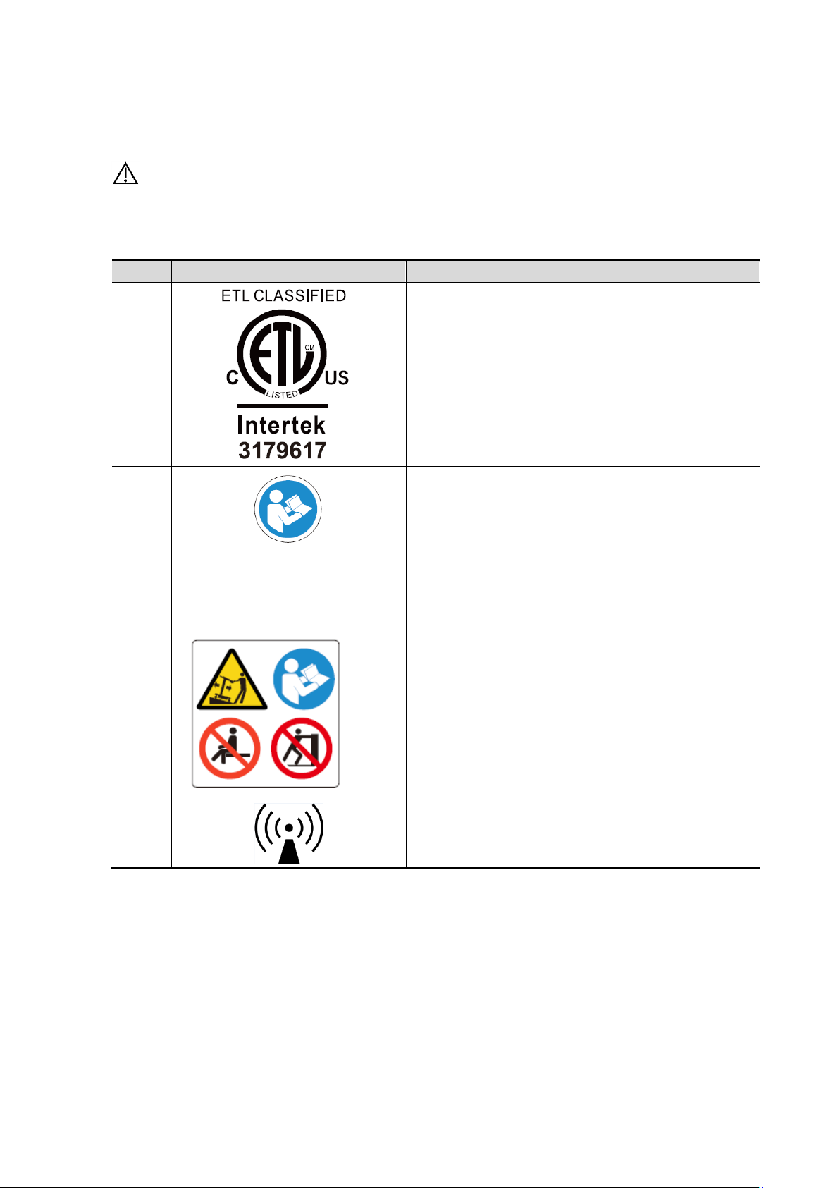
Symbol
Description
Type-BF applied part
The ultrasound probes connected to this system are type-BF applied parts.
The ECG leads within this system is type-BF applied part.
General warning sign.
Caution!
Patient/user infection due to contaminated equipment. Be careful when
performing cleaning, disinfection and sterilization.
Patient injury or tissue damage from ultrasonic radiation. The ALARA
principle must be practiced when operating the ultrasound system.
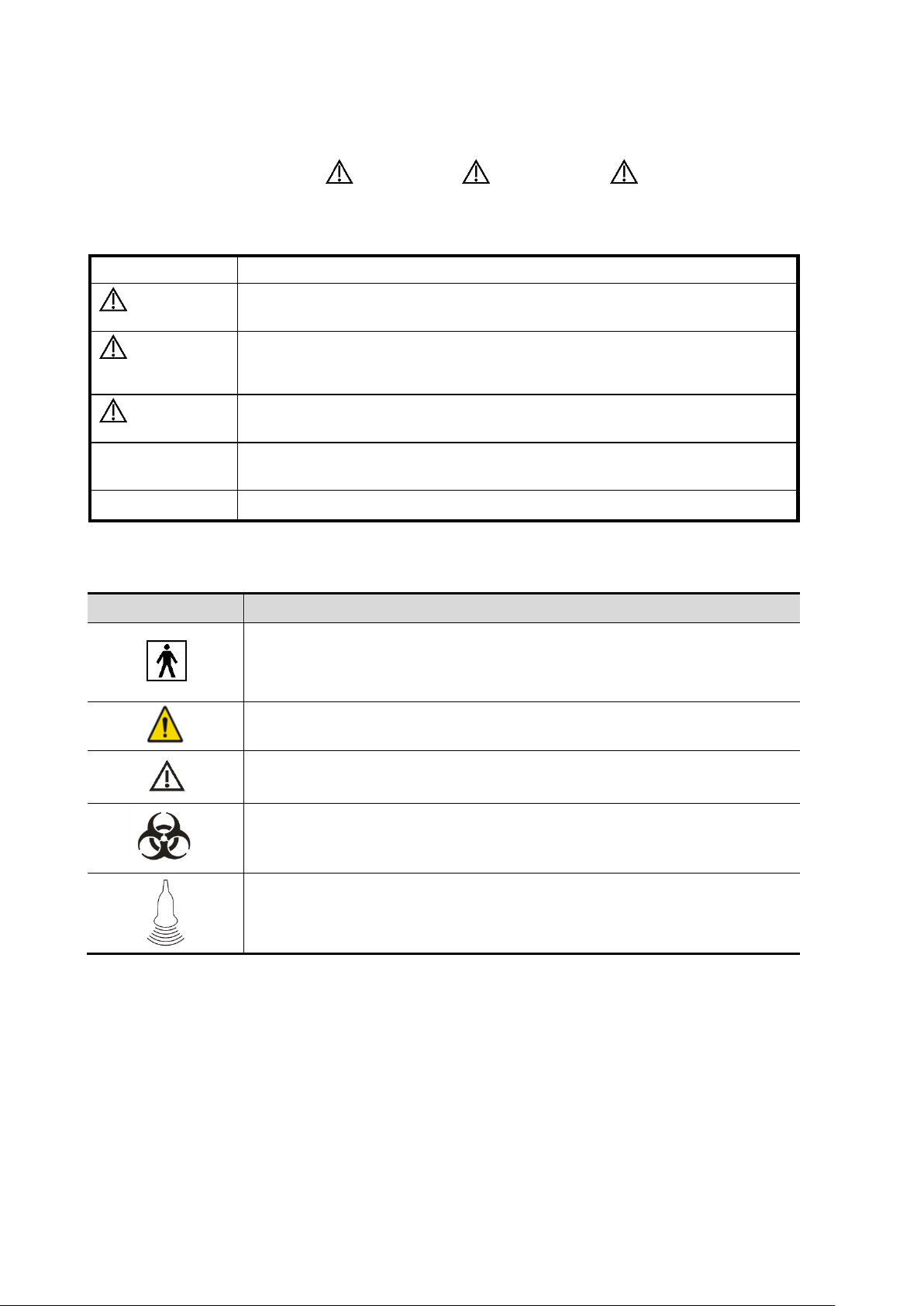
1.2 Meanings of Signal Words
In this manual, the signal words DANGER, WARNING, CAUTION, NOTE
and Tip are used regarding safety and other important instructions. The signal words and their
meanings are defined as follows. Please understand their meanings clearly before reading this
manual.
1.3 Meaning of Safety Symbols
1-2 Safety Precautions
Page 15

DANGER:
DO NOT use flammable gasses, such as anesthetic gas or hydrogen,
or flammable liquids such as ethanol, near this system, because
there is danger of explosion.
WARNING:
1.
Do connect the adapter power plug of this system and
power plugs of the peripherals to well-grounded wall
receptacles that meet the ratings indicated on the rating
nameplate. Using a multifunctional receptacle may affect
the system protective grounding performance, and
cause the leakage current to exceed safety requirements.
Use the cable provided with this system to connect the
printer. Other cables may result in electric shock.
You must use the power adapter provided with the system;
otherwise electric shock may result.
You can only use the power supply method provided by
Mindray, other power supply modes (e.g. using a UPS) may
result in electric shock.
2.
Connect the protective grounding conductor before turning
ON the system. Disconnect the grounding cable after
turning OFF the system. Otherwise, electric shock may
result.
3.
For the connection of power and grounding, follow the
appropriate procedures described in this operator’s
manual. Otherwise, there is risk of electric shock. DO NOT
connect the grounding cable to a gas pipe or water pipe;
otherwise, improper protective grounding may result or a
gas explosion may occur.
4.
Before cleaning the system, disconnect the power cord
from the outlet. Failure to do so may result in system
failure and electric shock.
5.
This system is not water-proof designed. DO NOT use this
system in any place where water or any liquid leakage may
occur. If any water is sprayed on or into the system,
electric shock or device malfunction may result. If water is
accidentally sprayed on or into the system, power off the
system immediately and contact Mindray Customer Service
Department or sales representative.
6.
DO NOT use a probe that has a damaged, scratched
surface, or exposed wiring of any kind. Immediately stop
using the probe and contact Mindray Customer Service
Department or sales representative. There is risk of electric
shock if a damaged or scratched probe is used.
7.
DO NOT allow the patient to contact the live parts of the
ultrasound system or other devices, e.g. signal I/O ports.
Electric shock may occur.
1.4 Safety Precautions
Please observe the following precautions to ensure patient and operator’s safety when using this
system.
Safety Precautions 1-3
Page 16

8.
Do not use an aftermarket probe other than those specified
by Mindray. The probes may damage the system, causing a
profound failure, e.g. a fire in the worst case.
9.
Do not subject the probes to knocks or drops. Use of a
defective probe may cause an electric shock.
10.
Do not open the covers and front panel of the system.
Short circuit or electric shock may result when the system
hardware is exposed and powered on.
11.
DO NOT use this system simultaneously with equipment
such as an electrosurgical unit, high-frequency therapy
equipment, or a defibrillator, etc. This would result in a risk
of electric shock to the patient.
12.
When moving the system, you should first fold the LCD
display, disconnect the system from other devices
(including probes) and disconnect the system from the
power supply.
13.
Accessory equipment connected to the analog and digital
interfaces must comply with the relevant IEC standards
(e.g., IEC 60950 information technology equipment safety
standard and IEC 60601-1 medical equipment standard).
Furthermore, all configurations must comply with the
standard IEC 60601-1 chapter 16 ME System. It is the
responsibility of the person, who connects additional
equipment to the signal input or output ports and
configures a medical system, to verify that the system
complies with the requirements of IEC 60601-1 chapter 16
ME System. If you have any questions regarding these
requirements, consult your sales representative.
14.
Prolonged and repeated use of display controls may result
in hand or arm nerve disorders for some individuals.
Observe the local safety or health regulations concerning
the use.
15.
DO NOT contact both the patient and the ultrasound
system or the live parts of the ultrasound system (e.g.
signal I/O ports). Electric shock may occur.
16.
When using intra-cavity transducers, do not activate the
transducer outside the patient’s body.
17.
If you have any doubts of the installation or routing of
external protective cables, use the internal power supply
of the system.
18.
DO NOT put the ultrasound system in any soft materials
(e.g. soft cloth or cotton, etc.) in case that the air vent
becomes blocked.
19.
Always read and follow carefully the manufacturer
instructions on the contrast agent label.
20.
Only use the ECG leads provided with the ECG module;
otherwise electric shock may result.
1-4 Safety Precautions
Page 17

CAUTION:
1.
Precautions concerning clinical examination techniques:
This system must be used only by qualified medical
professionals.
This operator’s manual does not describe clinical
examination techniques. The clinician should select the
proper examination techniques based on specialized training
and clinical experience.
2.
Malfunctions due to radio waves:
If a device emitting radio waves is used in the
proximity of this system, it may interfere with
operations. DO NOT use or take any devices
transmitting RF signals (such as cellular phones,
transceivers and radio controlled products) into the
room where the system is located.
If a person brings a device that generates radio
waves near the system, ask him / her to immediately
turn OFF the device.
3.
Precautions concerning movement of the system:
When you place the system on the trolley and move
them together, you must secure all objects on the
trolley to prevent them from falling. Otherwise you
should separate the system from the trolley and
move them individually.
When you have to move the system with the trolley
upward or downward the stairs, you must separate
them first and then move them individually.
Object placed on the display may fall and injure an
individual when moving.
Confirm that there is no peripheral device connected
to the system before moving the system. Otherwise,
peripheral device may fall and cause injury.
4.
DO NOT expose the system to excessive vibration through
transportation. Mechanical damage may result.
5.
Do not connect this system to outlets with the same circuit
breakers and fuses that control the current of devices such
as life-support systems. If this system malfunctions and
generates over current, or when there is an instantaneous
current at power ON, the circuit breakers and fuses of the
building’s supply circuit may be tripped.
6.
Always keep the system dry. Avoid transporting this system
quickly from a cold place to a warm place; otherwise
condensation or water droplets may form allowing a short
circuit and possible electric shock.
7.
If the circuit protector is tripped, it indicates that the system
or a peripheral device was improperly shut down and that the
system is unstable. You cannot repair the system under this
circumstance and must call the Mindray Customer Service
Department or sales representative.
Safety Precautions 1-5
Page 18

8.
There is no risk of high-temperature burns during normal
ultrasound examinations. It is possible for the surface
temperature of the probe to exceed the body temperature of a
patient due to environmental temperature and exam mode
combinations. Apply the probe only for a period of time
required for the purpose of diagnosis.
9.
The system and its accessories are not disinfected or
sterilized prior to delivery. The operator is responsible for the
cleaning and disinfection of probes and sterilization of
biopsy brackets according to the manuals, prior to the use.
All items must be thoroughly processed to completely
remove harmful residual chemicals, which will not only be
harmful to the human body, but also damage the accessory.
10.
It is necessary to tap [End] in the bottom-left corner of the
operating panel to end the current scan that is in progress
and clear the current Patient Information field. Failure to do
so may result in new patient data being combined with data
of the previous patient.
11.
DO NOT connect or disconnect the system’s power cord or
its accessories (e.g., a printer or a recorder) without turning
OFF the power first. This may damage the system and its
accessories or cause electric shock.
12.
If the system is powered off improperly during operation, it
may result in data damage of the system’s hard disk or
system failure.
13.
Do not use the system to examine a fetus for a long period of
time.
14.
Do not use a USB memory device (e.g., a USB flash drive,
removable hard disk) which has unsafe data. Otherwise,
system damage may result.
15.
It is recommended to only use the video devices specified in
this manual.
16.
Do not use gel, disinfectant, probes, probe sheath or needleguided brackets that are not compatible with the system.
17.
Read the Acoustic Output Principle in the operation manual
carefully before operate this system on clinical examination.
18.
Please use the ultrasound gel compliant with the relevant
local regulations.
NOTE:
1.
DO NOT use the system in the vicinity of strong electromagnetic field (such as a
transformer), which may affect the performance of the system.
2.
DO NOT use the system in the vicinity of high-frequency radiation source, which
may affect the performance of the system or even lead to failure.
1-6 Safety Precautions
Page 19

3.
To avoid damaging the system, DO NOT use it in following environment:
(1) Locations exposed to direct sunlight.
(2) Locations subject to sudden changes in environmental temperature.
(3) Dusty locations.
(4) Locations subject to vibration.
(5) Locations near heat generators.
(6) Locations with high humidity.
4.
Turn ON the system only after the power has been turned OFF for a while. If the
system is turned ON immediately after being turned OFF, the system may not be
rebooted properly and could malfunction.
5.
When using or placing the system, keep the system horizontal to avoid
imbalance.
6.
Remove ultrasound gel from the face of a probe when the examination is
complete. Water in the gel may enter the acoustic lens and adversely affect the
performance and safety of the probe.
7.
You should properly back up the system to a secure external storage media,
including system configuration, settings and patient data. Data stored to the
system’s hard drive may be lost due to system failure, improper operation or
accident.
8.
Do not apply external force to the touch screen; otherwise, the system may be
damaged.
9.
If the system is used in a small room, the room temperature may rise. Please
provide proper ventilation and free air exchange.
10.
To dispose of the system or any part, contact Mindray Customer Service
Department or sales representative. Mindray is not responsible for any system
content or accessories that have been discarded improperly.
11.
Electrical and mechanical performance may be degraded due to long period of
usage (such as current leakage or distortion and abrasion); the image sensitivity
and precision may become worse too. To ensure optimal system operations, it is
recommended that you maintain the system under a Mindray service
agreement.
12.
Ensure that the current exam date and time are the same as the system date
and time.
13.
DO NOT turn OFF the power supply of the system during printing, file storage or
invoking other system operations. An interrupted process may not be completed,
and can become lost or corrupted.
14.
Use detachable power supply cord as mains power breaking device. DO NOT
set equipment in a place where it is difficult to disconnect the detachable power
supply cord!
Safety Precautions 1-7
Page 20

WARNING:
1.
The ultrasonic probe is only for use with the specified ultrasonic
diagnostic system. Please refer to the 2.3.2 Probes and Needle-
guided Brackets Available to select the proper probe.
2.
Confirm that the probe and cable are normal before and after
each examination. A defective probe may cause electric shock
to the patient.
3.
Do not subject the probe to shock. A defective probe may cause
electric shock to the patient.
4.
Do not disassemble the probe as this may cause electric shock
or malfunction.
5.
Never immerse the probe connector into liquids such as water
or disinfectant because the connector is not waterproof.
Immersion may cause electric shock or malfunction.
6.
A probe sheath must be installed over the probe before
performing intra-cavity or intra-operative examination.
CAUTION:
1.
When using the probe, wear sterile gloves to prevent infection.
2.
Be sure to use sterile ultrasound gel. Please use the ultrasound
gel compliant with the relevant local regulations. And manage
the ultrasound gel properly to ensure that it does not become a
source of infection.
3.
In normal diagnostic ultrasound mode, there is no danger of a
normal-temperature burn; however, keeping the probe on the
same region of the patient for a long time may cause such a
burn.
4.
Do not use the carrying case for storing the probe. If the carrying
case is used for storage, it may become a source of infection.
5.
It is required to practice ALARA when operating ultrasound
system. Minimize the acoustic power without compromising the
quality of images.
6.
The probe and the accessories supplied with it are not delivered
disinfected or sterilized. Sterilization (or high-level disinfection)
is required before use.
7.
Disposable components (for example the probe sheath, the
sterile gloves) are packaged sterile and are single-use only. Do
not use if the integrity of the packaging has been violated or if
the expiration date has passed. Use disposable components
which comply with the relevant local regulations.
8.
Please use the disinfection or sterilization solution that
recommended in this operator’s manual; otherwise Mindray will
not be liable for damage caused by other solutions. If you have
any questions, please contact Mindray Customer Service
Department or sales representative.
Please read the following precautions carefully to ensure the safety of the patient and the operator
when using the probes.
1-8 Safety Precautions
Page 21

9.
The probe sheath contains natural rubber that can cause allergic
reactions in some individuals.
10.
Do not use pre-lubricated condoms as a sheath. Lubricant may
not be compatible with the transducer material and damage may
result.
11.
Transducer damage may be caused by inappropriate gel,
detergent or cleanser:
Do not soak or saturate transducers with solutions containing
alcohol, bleach, ammonium chloride compounds, acetone or
formaldehyde.
Avoid contact with solutions or coupling gels containing mineral
oil or lanolin.
12.
The contrast agent used must comply with the relevant local
regulations.
NOTE:
1.
Read the following precautions to prevent the probe from malfunction:
Clean and disinfect the probe before and after each examination.
After the examination, wipe off the ultrasound gel thoroughly. Otherwise,
the ultrasound gel may solidify and the image quality would be degraded.
Safety Precautions 1-9
Page 22

2.
Ambient conditions:
To prevent the probe from being damaged, do not use it where it will be exposed
to:
Direct sunlight or X-rays
Sudden changes in temperature
Dust
Excessive vibration
Heat generators
Use the probes under the following ambient conditions:
ambient temperature: 0°C ~ 40°C
relative humidity: 30% ~ 85% (no condensation)
atmospheric pressure: 700 hPa ~ 1060 hPa.
Use the probe L14-5sp under the following ambient conditions:
ambient temperature: 10°C ~ 40°C
relative humidity: 30% ~ 85% (no condensation)
atmospheric pressure: 700 hPa ~ 1060 hPa.
Use the probe SC6-1s, SP5-1s, L11-3VNs, L12-3RCs, L14-5Ws and L9-3s under the
following working conditions:
ambient temperature: 0°C ~ 40°C
relative humidity: 20% ~ 85% (no condensation)
atmospheric pressure: 700 hPa ~ 1060 hPa.
Use the probe L20-5s under the following working conditions:
ambient temperature: 0°C ~ 35°C
relative humidity: 15% ~ 80% (no condensation)
atmospheric pressure: 700 hPa ~ 1060 hPa.
Use the probe C4-1s under the following working conditions:
ambient temperature: 0°C ~ 35°C
relative humidity: 15% ~ 90% (no condensation)
atmospheric pressure: 700 hPa ~ 1060 hPa.
3.
Repeated disinfection will eventually damage the probe, please check the probe's
performance periodically.
WARNING:
Allergic reactions in patients sensitive to latex (natural rubber) may
range from mild skin reactions (irritation) to fatal anaphylactic
shock, and may include difficulty breathing (wheezing), dizziness,
shock, swelling of the face, hives, sneezing, or itching of the eyes
(FDA Medical Alert on latex products, “Allergic Reactions to Latexcontaining Medical Devices”, issued on March 29, 1991).
1.5 Latex Alert
When choosing a probe sheath, it is recommended that you directly contact CIVCO for obtaining
information regarding probe sheaths, pricing, samples and local distribution. For CIVCO
information, please contact the following:
CIVCO Medical Instruments, Tel: 1-800-445-6741; www.civco.com
1-10 Safety Precautions
Page 23
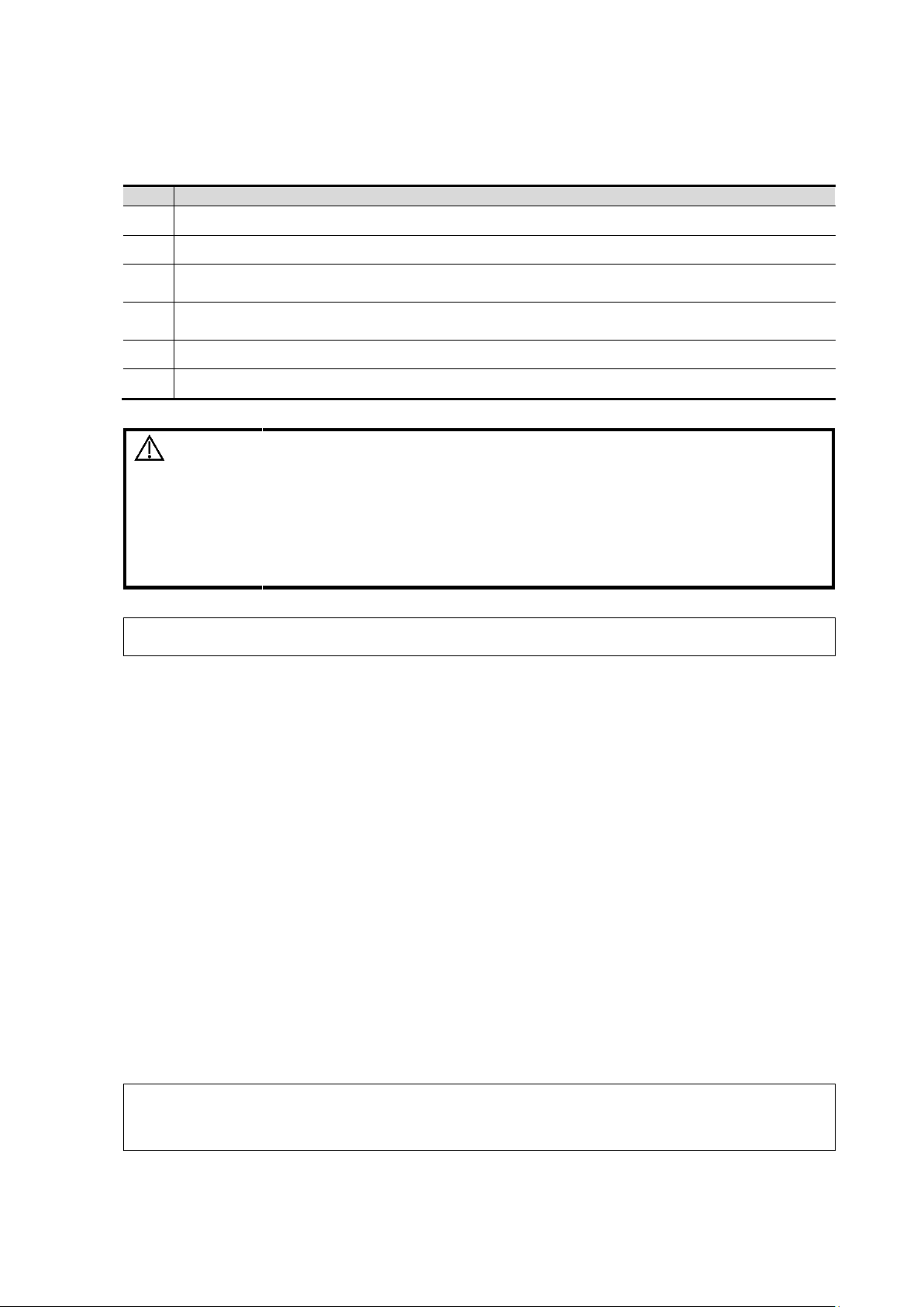
No.
Warning Labels
Meaning
1.
CONFORMS TO AAMI Std. ES 60601-1, IEC Std.
60601-2-37,IEC Std. 60601-2-18;
CERTIFIED TO CSA Std. C22.2 NO. 60601-1,
60601-2-37, 60601-2-18
2.
Read this information carefully before using the
system.
3.
The following labels are available
when the system works with the
mobile trolley.
(a) Do not place the system with the mobile trolley
on a sloped surface. Otherwise the system may
slide, resulting in personal injury or the system
malfunction. Two persons are required to move the
system over a sloped surface.
b DO NOT sit on the trolley.
c When the casters are locked, DO NOT push the
trolley.
4.
Non-ionizing radiation
a
b
c
1.6 Warning Labels
Warning labels are attached to this system to call your attention to potential hazards. The symbol
on warning labels indicates safety precautions.
The warning labels use the same signal words as those used in the operator’s manual. Read the
operator’s manual carefully before using the system.
The name, design and meaning of each warning label are described as follows:
Safety Precautions 1-11
Page 24

Page 25

NOTE:
The functions described in the operator’s manual may vary depending on the specific
system purchased.
Only TE7 is available in Canada.
B Mode
B
M Mode
M
Free Xros M
C Mode
Color
Power (DirPower)
D Mode
PW/CW
Special imaging
Smart 3D
TDI
Color M
Left Ventricular Opacification (LVO)
Contrast
Voltage
100-240V~;
19Vdc(DCU direct input)
Frequency
50/60Hz
Power input
2.0A (Power adapter)
3.5A (Trolley)
Fuse
T5AL, 250Vac (Power adapter)
Battery
14.8Vdc
2 System Overview
2.1 Intended Use
TE7/TE5 Diagnostic Ultrasound System is applicable for adults, pregnant women, pediatric
patients and neonates. It is intended for use in fetal, abdominal, intra-operative (abdominal,
thoracic, and vascular), pediatric, small organ (breast, thyroid, testes), neonatal and adult cephalic,
trans-esoph. (Cardiac), trans-rectal, trans-vaginal, musculo-skeletal (conventional, superficial),
urology, peripheral vessel, adult and pediatric cardiac, ophthalmic exams.
2.2 Product Specifications
2.2.1 Imaging Mode
2.2.2 Power supply
System Overview 2-1
Page 26

Operating conditions
Storage and transportation conditions
Ambient temperature
0°C~40°C
-20°C~55°C
Relative humidity
30%~85% (no condensation)
20%~95% (no condensation)
Atmospheric pressure
700hPa~1060hPa
700hPa~1060hPa
WARNING:
Do not use this system in conditions other than those specified.
2.2.3 Environmental Conditions
2.2.4 Dimensions and Weight
Dimensions (including probe holder): 130±10 (Depth) x 380±10 (Width) x 380±5 (Height) mm
Weight (including batteries, three-probe socket configuration and one probe): <8.2Kg.
2.3 System Configuration
2.3.1 Standard Configuration
Main unit (select configuration between one-probe socket and three-probe socket)
Batteries (built-in)
SSD card (built-in)
System software
Wireless adapter (built-in)
iScanHelper
Accessories
Operator’s manuals and operation note
Ultrasound gel (made by Eco-Med Pharmaceuticals, model: Eco Gel 200, K955246)
Probe holder
Applied part: probes.
2-2 System Overview
Page 27

Probe
model
Probe Type
Intended Use
Region Applied
C5-2s
Convex
Fetal, abdominal, pediatric, peripheral vessel
Body surface
C11-3s
Convex
Abdominal, pediatric, neonatal cephalic,
Cardiac Pediatric, peripheral vessel
Body surface
L12-4s
Linear
Ophthalmic, Abdominal, Pediatric, Small
organ, musculo-skeletal (conventional,
superficial), Peripheral vessel
Body surface
L7-3s
Linear
Abdominal, pediatric, small organ (breast,
thyroid, testes), musculo-skeletal
(conventional, superficial), peripheral vessel
Body surface
L14-6s
Linear
Pediatric, small organ (breast, thyroid, testes),
neonatal cephalic, musculo-skeletal
(conventional, superficial), peripheral vessel
Body surface
L14-6Ns
Linear
Ophthalmic, Pediatric, small organ (breast,
thyroid, testes), musculo-skeletal
(conventional, superficial), Peripheral vessel
Body surface
P4-2s
Phased
Fetal, Abdominal, pediatric, neonatal cephalic,
adult cephalic, cardiac adult, cardiac pediatric
Body surface
V11-3Ws
Convex
Fetal, trans-rectal, trans-vaginal, urology
Transvaginal
Trans-rectal
7LT4s
Linear
Abdominal, intra-operative (abdominal,
thoracic and vascular etc.), pediatric, small
organ (breast, thyroid, testes), neonatal
cephalic, musculo-skeletal (conventional,
superficial), peripheral vessel
Body surface/
intra-operative
P7-3Ts
Phased
Trans-esoph.(cardiac)
Transesophageal
L14-5sp
Linear
Abdominal, Intra-operative(abdominal, thoracic
and vascular etc.), Pediatric, small organ
(breast, thyroid, testes), Neonatal Cephalic,
musculo-skeletal (conventional, superficial),
peripheral vessel
Body surface/
intra-operative
P10-4s
Phased
Abdominal, pediatric, neonatal cephalic,
cardiac pediatric
Body surface
L20-5s
Linear
Ophthalmic, Small organ (breast, thyroid,
testes), musculo-skeletal (conventional,
superficial), peripheral vessel
Body surface
SC6-1s
Convex
Fetal, Abdominal, Pediatric, Musculo-skeletal
(Conventional), Peripheral vessel
Body surface
6CV1s
Convex
Fetal, Trans-rectal, Trans-vaginal, Urology
Trans-vaginal
Trans-rectal
7L4s
Linear
Abdominal, pediatric, small organ (breast,
thyroid, testes), neonatal cephalic, musculoskeletal (conventional, superficial), peripheral
vessel
Body surface
2.3.2 Probes and Needle-guided Brackets Available
System Overview 2-3
Page 28

Probe
model
Probe Type
Intended Use
Region Applied
P7-3s
Phased
Abdominal, pediatric, neonatal cephalic, adult
cephalic, cardiac adult, cardiac pediatric
Body surface
SP5-1s
Phased
Fetal, Abdominal, Pediatric, Neonatal
Cephalic, Adult Cephalic, Cardiac Adult,
Cardiac Pediatric
Body surface
L9-3s
Linear
Abdominal, Pediatric, small organ (breast,
thyroid, testes), musculo-skeletal
(conventional, superficial), Peripheral vessel
Body surface
L11-
3VNs
Linear
Abdominal, Pediatric, small organ (breast,
thyroid, testes), musculo-skeletal
(conventional, superficial), Peripheral vessel
Body surface
C5-1s
Convex
Fetal, Abdominal, Pediatric, Peripheral vessel
Body surface
C4-1s
Convex
Fetal, Abdominal, Pediatric, Musculo-skeletal
(Conventional), Cardiac Adult
Body surface
L14-5Ws
Linear
Abdomen, Pediatric, small organ (breast,
thyroid, testes), musculo-skeletal
(conventional, superficial), Peripheral vessel
Body surface
L12-
3RCs
Linear
Abdominal, Pediatric, small organ (breast,
thyroid, testes), musculo-skeletal
(conventional, superficial), Peripheral vessel
Body surface
Probe model
Needle-guided
Bracket Model
Biopsy
angle/depth
(±1°)
Applicable Biopsy Needle
V113Ws/6CV1s
NGB-004
metal/needle
non-detachable
/
16G, 17G, 18G
L12-4s/ L7-3s/
L14-6Ns/ 7L4s
NGB-007
plastic/needle
detachable
metal/needle
detachable
40°, 50°, 60°
Metal: 14G, 16G, 18G, 20G, 22G
Plastic: 13G, 15G, 16G, 18G, 20G
7LT4s
NGB-010
(metal/needle
detachable)
30°, 40°, 50°
13G, 15G, 16G, 18G, 20G
P4-2s/SP5-1s
NGB-011
metal/needle
non-detachable
11°, 23°
13G, 15G, 16G, 18G, 20G
C5-2s
NGB-015
Metal/needle
detachable
25°, 35°, 45°
14G, 16G, 18G, 20G, 22G
Some of the probes have corresponding needle-guided brackets for biopsy. The available probes
and the corresponding needle-guided brackets are listed as follows:
2-4 System Overview
Page 29

Probe model
Needle-guided
Bracket Model
Biopsy
angle/depth
(±1°)
Applicable Biopsy Needle
L14-6s
NGB-016
Metal/needle
detachable
30°, 40°, 50°
14G, 16G, 18G, 20G, 22G
C11-3s
NGB-018
metal/needle
detachable
15°, 25°, 35°
14G, 16G, 18G, 20G, 22G
SC6-1s/ C5-1s
NGB-022
Metal-needle
detachable
25°, 35°, 45°
Metal: 14G, 16G, 18G, 20G, 22G
L9-3s
NGB-034
Metal-needle
detachable
40°, 50°, 60°
4G, 16G, 18G, 20G, 22G
L14-5Ws
NGB-035
Metal-needle
detachable
47°, 53°, 59°, 65°
14G、16G、18G、20G、22G
C4-1s
NGB-036
Metal-needle
detachable
7°, 25°, 35°
14G、16G、18G、20G、22G
Probe model
Needle-guided Bracket Model
L14-6Ns、L12-4s
CIVCO 658-001
C5-2s
CIVCO 658-002
L14-5sp
CIVCO 698-006
C4-1s
CIVCO 698-019
V11-3Ws
CIVCO 610-543
V11-3Ws
CIVCO 610-1274
L14-5Ws
CIVCO 698-007
L14-5Ws
CIVCO 698-012
NOTE:
Some features may not be available in some countries due to pending regulatory
approvals.
Disposable needle-guided bracket
Some of the probes have corresponding disposable needle-guided brackets for biopsy. The
available probes and the corresponding disposable needle-guided brackets are listed as follows
Note: The disposable needle-guided brackets are not configured or sold by Mindray. The user can
purchase them based on the specific needs. See CIVCO for the use of each disposable needleguided bracket.
System Overview 2-5
Page 30

2.3.3 Options
No.
Item
Remarks
1.
Footswitch
Types: 2-pedal/3-pedal
2.
Trolley See chapter “Appendix D Trolley and Accessories” for details.
3.
Wall mount/Table stand
After the wall mount/table stand is configured,
power adapter and cables should be
configured.
4.
Power adapter
Table stand or wall mounting bracket should
be configured.
5.
Power cable
The power adapter should be configured.
6.
ECG module
The ECG module should be configured.
7.
ECG cables
ECG module should be configured.
8.
DC-IN cable
ECG module should be configured.
9.
Travelling case
After the travelling case is configured, power
adapter and cables must be selected.
10.
External DVD recorder
/
11.
Barcode reader
/
12.
Trolley box
/
13.
iVocal microphone
/
14.
CW
/
15.
LVO
/
16.
iNeedle
/
17.
Abdomen/General Package
/
18.
Obstetrical Package
/
19.
Gynecology Package
/
20.
Cardiac Package
/
21.
Small Parts Package
/
22.
Urological Package
/
23.
Vascular Package
/
24.
Nerve Package
/
25.
Emergency & Critical Package
/
26.
Pediatrics Package
/
27.
DICOM
DICOM Basic (including verify
(SCU and SCP), task
management, DICOM Storage,
DICOM Print, DICOM Storage
Commitment, DICOM Media
Storage (including DICOM
DIR))
/
DICOM Worklist
DICOM Basic should be configured.
2-6 System Overview
Page 31

No.
Item
Remarks
DICOM MPPS
DICOM OB/GYN SR
DICOM Vascular SR
DICOM Cardiac SR
DICOM Query/Retrieve
DICOM Breast SR
28.
Free Xros M
Not applicable for Canada.
29.
Tissue Doppler Imaging
Cardiac Package should be configured.
30.
IMT
Vascular Package should be configured.
31.
Auto EF
Cardiac Package should be configured.
32.
eSpacialNavi
/
33.
Contrast Imaging
/
34.
Contrast Imaging QA
/
35.
iWorks
/
36.
DVR Module
/
37.
McAfee
/
No.
Item
Model
1.
Black/white video printer(digital)
MITSUBISHI P95DW-N
SONY UP-D898MD
SONY UP-X898MD
2.
Black/white video printer (analog)
SONY UP-X898MD
3.
Digital color video Printer
SONY UP-D25MD
4.
Barcode reader
LS2208
DS4308
JADAK HS-1M
JADAK HS-1R
5.
Footswitch
1266262
1229155
971-SWNOM (2-pedals)
971-SWNOM (3-pedals)
6.
External DVD R/W drive
SDRW-08D2S-U
7.
iVocal
SAMSON XPD1 Headset
SAMSON XPD1 Presentation
PYLE PUSBMIC43
2.3.4 Peripherals Supported
System Overview 2-7
Page 32

NOTE:
1. If the ultrasound system cannot recognize the SONY UP-X898MD and SONY
UP-D898MD printers automatically, you may need to change the settings on the
printer: push <PUSH ENTER> to enter the main menu and select
[DIGITAL]->[DRIVER], and select [897].
2. USB cable length of the printers should be within 5-6 ft, otherwise the lifting of
the trolley will be affected if the USB cable is too short or even the ultrasound
system and the printer cannot be connected; or it’s not easily to arrange the
cable tidily if the USB cable is too long.
WARNING:
This system complies with IEC60601-1-2:2007, and its RF
emissions meet the requirements of CISPR11 Class B. In a
domestic environment, the customer or user should
ensure the system is connected to Class B peripheral
devices, otherwise RF interference may occur, and the
customer or user must take adequate measures
accordingly.
Parts that can be used within patient environment:
Main unit;
Probes;
Footswitch;
Printers: MITSUBISHI P95DW-N, SONY UP-D25MD, SONY UP-D898MD, SONY UP-
X898MD.
2.4 Introduction of Each Unit
2-8 System Overview
Page 33

No.
Name
Function
<1>
Touch screen and display
Operator-system interface or control; displays the image
and parameters during the scan.
: Battery status indicator.
Charging status:
It illuminates in orange when batteries are charging;
It illuminates in green when batteries are charged fully.
Discharging status:
It illuminates in green color when the power of the
batteries is sufficient;
It blinks in orange color for low battery power.
: AC indicator
The indicator is green at AC supply.
The indicator is off when batteries are supplied without
AC supply.
: Standby indicator.
Standby: blinking in orange.
Other status: light off.
<2>
Telescoping handle
Used for moving the system occasionally.
<3>
Intra-cavity probe holder
Used for placing the probe.
<4>
Probe locking switch
Locks or unlocks the probe connecting with the main unit.
<5>
Probe port
Connects a probe to the main unit.
<6>
Probe holder
Used for placing the probe.
<7>
Kensington lock
Locks the main unit to the trolley in case of loss.
<8>
Power inlet
Connects with the power adapter.
<9>
Serial port for connecting
ECG
Connects with the ECG module
<10>
HDMI
Used for extending the monitor.
<11>
USB ports
Connects USB devices.
System Overview 2-9
Page 34

No.
Name
Function
<12>
Network port
Connects to network.
NOTE:
Mindray recommends using Category 2-certified HDMI output cables (marked as “High
Speed”) according to HDMI 1.3 standard for a good output effect. Otherwise, abnormal
display effect may result. You can use a HDMI-to-DVI adapter for outputting to a
display with DVI input.
When connecting TE7/TE5 with an external display or recording devices via HDMI,
choose a right output setting resolution ([Setup] ->[System] ->[Peripheral] -> [Display]),
and please make sure the scan rate of 60Hz progressive is supported by the external
device, otherwise malfunction may result.
Symbol
Description
Caution!
Standby
Type-BF applied part
No user serviceable parts (power adapter)
Battery installation position
Product serial number
Manufacture date
Battery status indicator
AC (Alternating current)
Standby status indicator
Probe connector unlocking symbol
Probe connector locking symbol
Extending port
HDMI
HDMI port
USB port
Network port
2.5 Symbols
This system uses the symbols listed in the following table. Their meanings are explained as
follows:
2-10 System Overview
Page 35

Symbol
Description
Probe socket
Power consumption
Maximum load for printer bracket on the trolley
Trolley input
Trolley output
Maximum load for storage bin on the trolley
System Overview 2-11
Page 36

Page 37

CAUTION:
Maintain a generous, free air flowing space around the back and
both sides of the system. Not doing so may result in failure due to
the increased rise in the system's operating temperature.
3 System Preparation
3.1 Move/Position the System
Read and understand the safety precautions before positioning the system to ensure the safety of
both the operator and the devices.
1. Switch off the power, and pull out the power plug.
2. Disconnect all cables from off-board peripheral devices.
3. Place the system in a desired location.
4. Leave at least 20cm at the back and both sides of the system.
System Preparation 3-1
Page 38

3.2 Power ON/OFF
CAUTION:
To ensure safe and effective system operation, you must perform daily
maintenance and checks. If the system begins to function improperly,
immediately stop scanning. If the system continues to function
improperly, fully shut down the system and contact the Mindray
Customer Service Department or a sales representative. If you use the
system in a persistent improperly functioning state, you may harm the
patient or damage the equipment.
No.
Check Item
1
The temperature, relative humidity and atmospheric pressure meet the requirements of
the operating conditions. See “2.2.3 Environmental Conditions” for details.
2
There is no condensation.
3
There is no distortion, damage or dirt on the system and peripheral devices.
If any dirt is found, cleaning should be performed as illustrated in section “17 System
Maintenance.”
4
There are no loose screws on the display or the trolley.
5
There is no cable damage (e.g., power cord).
Maintain secure connections to the system at all times.
6
The probes and probe cables are free from damage or stains.
See chapter “13 Probes and Biopsy” for details of probe cleaning and disinfection.
7
No miscellaneous odds and ends are attached or affixed to the display.
8
Ensure that all connections are free from damage and remain clear of foreign object
blockages.
There are no obstacles around the system and its air vent.
9
Probe cleaning and disinfection.
10
The entire scanning environment and field must be clean.
11
The locking mechanism of the casters (if there is a trolley) works normally.
3.2.1 Power the System ON
Check before Powering ON
Check before the system is powered on:
3-2 System Preparation
Page 39
No.
Check Item
1
There are no unusual sounds or smells indicating possible overheating.
2
There are no persistently displayed system error messages.
3
There is no evident excessive noise, or discontinuous, absent or black items in the B
mode image.
4
Check whether there is abnormal heat on the surface of the probe during an ultrasound
procedure. If you use a probe which is giving off excessive heat, it may burn the patient.
5
The display (main screen) can respond functionally.
6
The date and time are displayed correctly.
WARNING:
If you use a probe giving off excessive heat, it may
burn the patient.
If you find anything not functioning properly, this may indicate
that the system is defective. In this case, shut down the system
immediately and contact Mindray Customer Service
Department or sales representative.
NOTE:
When you start the system or switch between transducers, you may hear clicking
sounds – this is expected behavior.
NOTE:
DO NOT rush direct shutdown of the system. It may damage the data.
After the system is upgraded, use “Shut Down” to power the system off to make the
upgraded data effective.
Check the system after it is powered on
Press the power button at the right side of the ultrasound system to power the system on.
Check after the system is powered on:
3.2.2 Power the System OFF
You must follow the correct procedures to power the system off. Also, after you upgrade the
software or when the system is down, you need to power off and restart it.
If you will not use the system for a long period of time, you should:
1. Disconnect the power adapter.
2. Disconnect the mains power.
3. Turn off powers of all peripherals connected to the system.
To power the system off normally
1. Press the power button at the right side of the ultrasound system to see the option:
Shut down: to power the system off normally.
Standby: to enter standby status.
Cancel: to cancel the operation.
2. Select [Shut Down] to power the system off.
To shut down the system directly if it cannot be done normally:
Press and hold the power button for a long time and the system will power off without displaying
the “Shutdown Confirm” screen. However, shutting down the system this way may destroy the
data.
System Preparation 3-3
Page 40

NOTE:
Power off the system if the system will not be used for a long period of time (including
storage/ transportation condition), and do not leave the system in standby status,
otherwise the batteries will run out of power and be permanently damaged.
If the system will not be used for a long period of time, you should disconnect the
power adapter, disconnect the mains power, and turn off the power to all peripherals
connected to the system.
3.2.3 Standby
To enter standby:
Select [Setup] -> [System] -> [General] to set the time for screensaver and standby. If the
system is not carrying out an operation, the screensaver appears after the screensaver
delay period. If there is still no operation, the system enters standby after the standby
delay period.
Press the power button and select [Standby].
To exit standby:
Touch the screen lightly or press the power button.
Under the standby status:
Exit standby status and power off the system after 5s.
3-4 System Preparation
Page 41

NOTE:
You must use the specified power adapter.
Do not use this power adapter in conditions other than those specified.
3.3 Connecting the Power Cord
This system can work normally only when it is connected to the external power supply or the
battery capacity is sufficient.
3.3.1 Connecting Power
1. Connect the connector of the power adapter to the adapter port in the system.
2. Use a three-wire cable to connect the adapter with the external power supply.
3. The external power supply must meet the requirements in chapter “2.2.2 Power supply”.
If you have any question about the power adapter, please contact your sales representative.
3.3.2 Powered by Batteries
When connecting to the external power supply, the system is powered by the external power.
The lithium ion batteries inside it are in the charging status.
If disconnected from the external power supply, the system is powered by the lithium ion
batteries. Refer to “Appendix B Battery” for the detailed operations and precautions.
System Preparation 3-5
Page 42

CAUTION:
Tap [Freeze] to freeze an image or turn off the system power
before connecting or disconnecting a probe. Failure to do
so may result in system or probe failure.
When connecting or disconnecting a probe, place it in the
proper position to prevent the probe from falling off or
becoming damaged.
Only use probes provided by Mindray. Aftermarket probes
may result in damage or cause a fire.
WARNING:
The probes, cables and connectors should be in
proper operating order and free from surface
defects, cracks and peeling. Otherwise, this may
lead to electrical shock.
NOTE:
Before inserting the connector into the probe port, inspect the connector pin. If the pin
is bent, do not use the probe until it has been inspected/repaired/replaced.
Locking lever
3.4 Connecting a Probe
3.4.1 Connecting a Probe
1. Keep the cable end of the transducer to the right side of the system; insert the connector into the
system port, then press in fully
2. Toggle the locking lever to the left position.
3. Position the probe properly to avoid it being treaded on or becoming wrapped around other
devices. DO NOT allow the probe head to hang free.
3-6 System Preparation
Page 43

WARNING:
DO NOT connect more than one wireless
footswitch receiver to the ultrasound system at
the same time; otherwise, malfunction may result.
WARNING:
DO NOT directly remove a USB memory device,
as the USB device and/or the system may become
damaged.
NOTE:
If the USB flash drive cannot be recognized by the system, please try disconnecting
and then connecting again several times, or try another USB flash drive. If the problem
still exists, please contact Mindray service engineer.
3.4.2 Disconnecting a probe
1. Turn the locking lever to the right position to unlock the connector.
2. Pull the probe connector straight out as shown in the figure below.
3.5 Connecting the Footswitch
The system supports USB port-type footswitches and wireless type footswitches.
The function of the foot switch can be preset. See chapter “12.1.6 Footswitch” for details.
3.6 Connecting USB Devices
When connecting a USB memory device to the ultrasound system via a USB port, a sound is
heard if it is connected successfully and the symbol appears in the top-right corner of the
screen.
To remove the USB device: tap to open the [Remove USB Device] screen. Select the
device to be removed and tap [OK]. A sound is heard when removing the USB memory device.
The system supports option of external DVD R/W drive. The DVD R/W drive is connected to
the ultrasound system via USB port.
System Preparation 3-7
Page 44

NOTE:
Printers listed in “2.3.4 Peripherals Supported” chapter have drivers installed already.
Data cable
USB port
Power supply
cable
3.7 Installing a Graph/Text Printer
Connecting a local printer
As shown in the figure below, a graph / text printer has a power cord and data cable. The
power cord should be directly plugged into a well-grounded outlet.
1. Connect the data cable to the USB port on the ultrasound system.
2. Power the system and the printer on.
3. Put the installation optical disk of the printer driver into the external DVD R/W drive.
4. Install the printer driver: Select [Setup] -> [System] -> [Peripheral] -> [Add Printer].
5. Select [Add a local printer] and tap [Next] to enter the screen used for browsing driver.
3-8 System Preparation
Page 45

NOTE:
See the printer’s operation manual to select the port, or try to use the default port of
the system.
NOTE:
When you install the printer’s driver, you must specify the specific path for installation.
A vague path may result in longer searching times.
The network printer functions depending on the configured network environment in the
hospital, please consult the network configuration manager in case of failure.
6. Tap [Have Disk] to find the driver path (the installation type should be WIN7 64), and then tap
[Next] to install the driver.
7. Complete the operation according to the tips on the screen. Tap [Finish] to end the installation.
Add network printer
1. As the system is connected into a LAN, open [Setup] -> [System] -> [Peripheral] screen.
2. Tap [Add Printer], select [Add a network, wireless or Bluetooth printer].
3. The system starts to search all available printers within the network. Select the target printer and
tap [Next], the system tries to connect to this printer.
4. When the connection is successful, the system prompts the dialogue box, tap [Next] according to
the screen tips and then tap [Finish].The printer is installed successfully.
Tips: the system has combined many types/brands of printer drivers, if targeted printer driver is not
included in the system, you may need to install the driver for the network printer. Please use the
optical disk or USB flash drive with the driver to install according to the system prompts.
Please refer to the accompanying manuals of the printers for details.
System Preparation 3-9
Page 46

NOTE:
Avoid operating in direct sunlight or the touch screen could be obscured.
3.8 Installing a Video Printer
The system support video printers, consist of the B/W digital printers and color digital printers.
1. Position the printer in the proper place.
2. Plug the printer power cord into an appropriate outlet.
3. Use a USB cable to connect between the system's USB port and the printer's USB port.
4. Load a paper roll, and turn on the system and printer.
5. See section “3.7 Installing a Graph/Text Printer” for the driver installation procedure (printer
drivers listed in chapter “2.3.4 Peripherals Supported” are installed already).
3.9 Brightness and Contrast Adjustment
1. Tap in the top-right corner of the screen to open the system tool bar.
2. Drag the slider to change the brightness/contrast on the brightness control or contrast
control .
3-10 System Preparation
Page 47

3.10 Display Position Adjustment
Gently hold the bottom edge of the display when adjusting its position.
When positioned vertically, the display can be tilted for 50° backward and 20° forward.
System Preparation 3-11
Page 48

1.
Probe model, acoustic output value and
MITI index
2.
Parameter area
3.
iNeedle
4.
iTouch
5.
Frequency adjustment
6.
TGC control
7.
Operating panel
8.
Patient Information area
9.
System status icon
10.
System tool bar
11.
Gain control
12.
Depth control
3.11 Basic Screen & Operation
3.11.1 Screen Display
3-12 System Preparation
Page 49

1
3 4 2
3.11.2 Operating panel
Operating panel located under the image area; consists of imaging mode buttons, menu area and
exam related buttons.
1. Imaging mode area
Tap imaging buttons to start imaging.
2. Menu area
Imaging parameter menu: swipe the menu downwards/upwards to see parameter controls;
Cine review menu (under frozen or cine review status);
Measurement menu;
Annotation and body mark menu.
3. Exam operating area
Tap each button to enter the screen.
Patient information;
Exam mode and probe switching;
iStation;
Image review;
Report review.
4. Other buttons
You can perform operations using those buttons, including end exam, switching modes, save
an image/cine, print single frame image or freeze/unfreeze image, etc.
System Preparation 3-13
Page 50

Notes:
When the iVocal function is enabled, the system can perform
operations both through inputting vocal commands and through
tapping icons on the touch screen.
The ultrasound system can automatically recognize some vocal
commands. For details about the vocal commands, please refer to
"17.2Appendix H List of Vocal Commands".
3.11.3 iVocal
Before enabling the iVocal function, ensure that the microphone device and the ultrasound system
is properly connected through the USB extension wire.
Tips: If the microphone is not to be used for the moment, you can put the microphone into the
vacant probe holder temporarily.
Vocal command inputting procedures:
1. Tap the icon in the Audio Control menu to start the vocal command recognition;
2. Input a vocal command using the microphone, and after the command is recognized, the
system automatically performs the corresponding operation.
3. Tap the icon in the Audio Control menu to pause the vocal command recognition;
3-14 System Preparation
Page 51

Currently, only wireless microphone devices can be inserted to the
system for inputting vocal commands.
4. Tap [iVocal] to exit the Audio Control menu.
Setup
Tap the icon in the Audio Command menu to check the system recognizable commands
and enter the iVocal Setup menu.
Add: tap [Add] to enter the Adding New Command menu, tap [Function Description] to
select the desired function, enter the user-defined command in the [Command] text box, and
then select OK.
User-defined command naming rules: only Chinese characters, English letters, and digits are
supported; the English letters are case-insensitive, consecutive blank spaces are not
supported, and a maximum of 128 letters are allowed when entering the English letters; Blank
spaces are not supported and a maximum of 30 characters are allowed when entering the
Chinese characters; the user-defined commands cannot be empty; User defined commands
System Preparation 3-15
Page 52

that are already exited in the system but represent different functions are not supported to be
added.
Test: Tap [Test] and input a vocal command to the microphone device. After the vocal
command is recognized, the Success Rate is displayed in fraction. Tap [Test] again to close
the vocal command test.
Note: if the vocal command is successfully recognized by the system, both the denominator
and numerator of the Success Rate are added by 1 for each time; if the vocal command fails
to be recognized by the system, the denominator of the Success Rate is added by 1 for each
time through tapping the icon, while the numerator remains the same. For example: 2/3
represents 2 times of success and 1 time of failure.
Clear: Tap [Clear] to clear all the Success Rate test records.
Recover: Tap [Recover] to enter the Confirm menu. You can select Yes to restore to the
default settings.
3-16 System Preparation
Page 53

Icon
Function
Audition the vocal command
Delete the vocal command
Rename the vocal command
Add the failure time by 1
Clear the Success Rate test record
of the selected vocal command
System Preparation 3-17
Page 54

Page 55

CAUTION:
Before examining a new patient, tap [End] in the bottom-left
corner of the operating panel to end the exam of the previous
patient. Update the patient ID and information to avoid mixing
data between patients.
4 Exam Preparation
A patient exam can be started under the following situations:
New patient information: to start a new patient exam, patient information must first be entered.
New exam: to start a new exam for patient who is already registered, the recorded information
can be obtained through either iStation or Worklist. See chapter “4.1.2 Retrieve Patient
Information” for details.
Activate exam: to select an exam that has been completed within 24 hours, continue the exam
with imported patient information and exam data.
General procedure for an exam:
Enter the patient information –> select an exam mode and probe –> Choose an imaging mode ->
Start the exam.
Tips: The system supports image scanning and measurement without patient information.
4.1 Patient Information
To start a new patient exam, it is best to enter detailed patient information. The system will set up a
unique information database for each patient based on the patient information entered, so that the
information of one patient will not be confused with that of another patient.
To enter the Patient Info screen
Tap [Patient] on the left side of the operating panel.
To exit the Patient Info screen
Tap [Done] on the Patient Info screen.
Tap [Cancel] on the Patient Info screen to exit the screen without saving any of the entered
patient data.
Exam Preparation 4-1
Page 56

4.1.1 New Patient Information
2
1
3
The Patient Info screen is shown as follows:
4-2 Exam Preparation
Page 57

Primary indications:
To enter the primary indications (reason for performing the exam.)
Accession #
To enter the exam number used in DICOM.
MRN:
To enter the secondary indications.
Diagnostician:
Person responsible for the exam.
Operator:
Person responsible for image collection and scanning.
Ref. Physician:
Person who requires the operator to carry out the ultrasound.
Comment:
To enter the exam-specific explanation or remarks.
Tap to select the desired field. The field box is highlighted and a flashing cursor appears.
Information can be entered or selected from the options.
Information includes:
1. General information
Patient ID
The Patient ID is generated automatically by the system after starting a new patient, and can
be modified manually.
The ID can also be obtained using the bar code reader.
Tip: you can change patient ID when there is no other exams of the current patient in the
system (including the recycle bin) and the exam is the current active exam.
Name
Gender
DOB (date of birth):
Age
Auto-generated age: once the DOB is obtained, the system displays an auto-generated
age in the field box. The unit can be “Years”, “Months” or “Days.” If the age is less than
one year, the system will automatically calculate the age in months or days.
You can also enter the age manually.
2. Exam information
Exam application type
You can select from: ABD (Abdomen), OB (Obstetrics), GYN (Gynecology), CARD (Cardiac),
VAS (Vascular), URO (Urology), SMP (Small Part) and BREAST (Breast).
Select the exam type drop-down list to enter exam-specific information.
General information:
To delete history entered information:
a) Tap and hold the drop-down list of the item: Operator, Diagnostician or Ref. Physician.
b) Tap to delete.
Exam Preparation 4-3
Page 58

Exam-specific information:
Exam Type
Information
Description
General
information
Height
/
Weight
/
ABD
(Abdomen)
BSA (body
surface
area)
After the height and weight are entered, the system will
automatically calculate the BSA based on the formula which is
set via [Setup] -> [System] -> [General].
OB
(Obstetrics)
Calculation
index
Calculate the gestation age (GA) and estimated delivery date
(EDD) based on the last menstrual period (LMP), date of
conception (DOC), in vitro fertilization (IVF), basic body
temperature (BBT) and previous exam date (PRV). Select LMP,
DOC, IVF, PRV, BBT, or EDD from the drop-down list, or
calculate the GA and LMP according to the EDD and entered
date.
LMP: after you enter the LMP, the system will calculate
the GA and EDD.
DOC: after you enter the DOC, the system will calculate
the GA and EDD.
IVF: after you enter IVF, the system will calculate the GA
and EDD.
PRV: enter the date and GA of the last exam, the system
will calculate a new GA and EDD.
BBT: enter the BBT, the system will calculate the GA and
EDD.
EDD: after you enter the EDD, the system will calculate
and display the GA and LMP.
Gravida
Times of pregnancy.
Ectopic
Times of abnormal pregnancy, e.g., extrauterine pregnancy
Gestations
Number of embryos (1, 2, 3, 4)
Para
Times of delivery.
Aborta
Times of abortion.
GYN
(Gynecology)
LMP
Last menstrual period.
Gravida
Times of pregnancy.
Para
Times of delivery.
Ectopic
Times of abnormal pregnancy, e.g., extrauterine pregnancy.
Aborta
Times of abortion.
CARD
(Cardiology)
BSA (body
surface
area)
After the height and weight are entered, the system will
automatically calculate the BSA based on the formula which is
set via [Setup] -> [System] -> [General].
BP
Blood pressure.
HR / RA Press
Right Atrium Pressure.
VAS
(Vascular)
BP(L) (blood
pressure)
Input left blood pressure.
4-4 Exam Preparation
Page 59

Exam Type
Information
Description
BP(R)
(blood
pressure)
Input right blood pressure.
URO
(Urology)
Serum PSA
/
PPSA
coefficient:
/
SMP (Small
Parts)
None
/
Breast
None
/
3. Functional controls:
[iStation]/[Worklist]: imports patient data from iStation or DICOM Worklist. See chapter
“4.1.2 Retrieve Patient Information” for details.
[Done]: saves the patient data entered and exits the screen.
[Cancel]: cancels the patient data entered and exits the screen.
4.1.2 Retrieve Patient Information
You can import patient information from iStation or DICOM Worklist for anonymous patients.
4.1.2.1 Retrieve from iStation
Using iStation, the patient data can be obtained in iStation from the system hardware or USB
memory device. You can enter search conditions for the patient.
1. In Patient screen, select [iStation] in the bottom-left corner to enter the screen.
2. Select an exam: you can either swipe the screen downwards to search or using the keyword
filter.
3. The system enters the Patient screen, and the selected exam information is imported already.
4. Change the patient information if necessary and then tap [Done] to start exam.
Exam Preparation 4-5
Page 60

4.1.2.2 Retrieve from Worklist
Worklist is an option. To use Worklist function, you have to configure DICOM Basic and DICOM
Worklist options.
When the DICOM basic package is configured and the Worklist server has been set, tap [Worklist]
in the Patient Info screen to query or import the patient data. (For details about the Worklist server
setting, see chapter “11.1.3.3 DICOM Worklist Preset” chapter.)
Worklist can retrieve patient data of two kinds of protocols: DICOM and HL7.
1. In Patient screen, select [Worklist] in the bottom-left corner to enter the import screen.
2. Select the data source: select the server type (DICOM or HL7), choose a Worklist server in the
“Worklist Server” drop-down list, and all the patient exam records are listed.
4-6 Exam Preparation
Page 61

CAUTION:
If the exam mode is changed during a measurement, all measurement
calipers on the image will be cleared. The general measurement data will
be lost, but application measurement data will be stored in the reports.
3. Enter the search condition:
Set query criteria from Patient ID, Patient Name, MRN, Scheduled Station AE Title,
Worklist Server, Modality Type or Exam Date. Or select the search key, enter the
keywords, then tap [Query] to search.
To reset the criteria, tap [Clear].
4. Select the desired patient record in the displayed patient list.
5. Select the desired patient and tap [Done]. The patient information is imported into the system
and then an exam is started.
4.2 Select Exam Mode and Probe
Selecting exam mode
1. Tap [Probe] on the left side of the operating panel. The screen displays the following dialog box:
2. Tap to select the probe model and exam mode. The system exits the dialog box and enters the
selected exam mode and probe.
Exam Preparation 4-7
Page 62

Tap [Exit] to cancel the selection and exit the screen.
Tap and hold any exam mode until it floats, and then drag to change the exam mode list
sequence.
Tap [A-Z Sort] to sort exam modes by alphabetical order for each probe.
4.3 Select the Imaging Mode
Enter the imaging mode by tapping imaging buttons at the right part of the operating panel. Swipe
the area to see the hidden imaging modes.
For detailed operations in each imaging mode, see chapter “5 Image Optimization.”
4.4 End an Exam
Be sure to avoid mixing data between patients.
Before examining a new patient, tap [End] in the bottom-left corner of the operating panel to end
the exam of the previous patient.
4.5 Activate an Exam
On the iStation screen, select an exam record which was completed within 24 hours and select
[Options] -> [Activate Exam].
Tips:
The system can automatically load the patient information and exam data to continue the
exam.
For an activated exam, you can modify the patient ID if there are no other recorded exams
of this patient (including the recycle bin) in the system.
4-8 Exam Preparation
Page 63

WARNING:
The images displayed in this system are for
reference only. Mindray is not responsible for the
correctness of diagnostic results.
Tissue Harmonic Imaging does not use contrast
agents.
5 Image Optimization
5.1 Imaging Mode
5.1.1 Switching Between Imaging Modes
On the operating panel, tap imaging mode buttons on the right to switch the mode.
Current imaging mode is indicated by highlighting the button in blue. For instance, the above
status shows that the system is under B+Color+PW mode (triplex is turned on).
5.1.2 Image Adjustment
1. Tap [Image] on the operating panel to open the image parameter control menu under different
imaging modes.
2. Swipe the menu downwards/upwards to check and change parameter controls.
Image Optimization 5-1
Page 64

See the following imaging chapters for details.
5.1.3 Quickly Saving Image Settings
Create a new exam mode using current image settings (user-defined exam mode):
1. Tap [Quick Save] in the image menu to bring out the Quick Save dialogue box.
2. Enter the name in the box after “To ” to assign a name for a user-defined exam mode.
3. Tap [Save] to save the current image parameters for the user-defined exam mode.
Tip: the [Quick Save] control is available under all imaging modes.
5-2 Image Optimization
Page 65

Check image parameter and change layout:
1. Tap [Edit] to enter the screen for checking the current image menu display for the current
exam mode of the particular probe.
2. Tap and hold any parameter until it floats, then you can:
Drag upwards/downwards to change its position on the image menu;
Drag leftwards/rightwards to change its display on the image menu: drag it to the left
“Options” list to delete its display or drag it to the right “Selected” list to display the
parameter.
3. Tap [Save] to save the settings or tap [Cancel] to cancel changes you made.
Tip: the [Quick Save] and [Edit] controls are available under all imaging modes.
Image Optimization 5-3
Page 66

Parameter
F
D G FR
DR
Meaning
Frequency
Depth
Gain
Frame Rate
Dynamic Range
Description
To switch between the fundamental frequency and harmonic frequency as well
as select the corresponding frequency type. The real-time frequency value is
displayed in the image parameter area in the top-left corner of the screen, and if
harmonic frequency is used “F H” is displayed as the harmonic frequency value.
Select the different frequency values through at the left part of the image
area.
The adjusting range of the harmonic frequency values can be divided into 4
levels: penetration preferred (HPen), general mode (HGen), resolution preferred
(HRes), and the mode between penetration preferred and general mode (HPenGen).
The adjusting range of fundamental frequency values can be divided into 3
levels: penetration preferred (Pen), general mode (Gen), and resolution
preferred (Res).
Impacts
The system provides an imaging mode using harmonics of echoes to optimize
the image. Harmonic imaging enhances near-field resolution and reduces lowfrequency and large amplitude noise, so as to improve small parts imaging.
Select the frequency according to the detection depth and current tissue
features.
Description
To adjust the gain of the whole receiving information in B mode. The real-time
gain value is displayed in the image parameter area in the top-left corner of the
screen.
5.2 B Mode Image Optimization
B mode is the basic imaging mode that displays real-time images of anatomical tissues and
organs.
5.2.1 Basic Procedures for B Mode Imaging
1. Enter the patient information. Select an appropriate probe and exam mode.
2. Tap [B] on the right side of the operating panel to enter B mode.
3. Tap [Image] to open the image menu. Adjust the parameters to optimize the image.
4. Perform other operations (e.g., measurement and calculation) if necessary.
Tip: tap [B] to return to B mode at any time (except LVO mode).
5.2.2 B Mode Parameters
In B mode scanning, the image parameter area in the top-left corner of the screen displays the
real-time parameter values as follows:
5.2.3 B Mode Image Optimization
Frequency (Image Quality)
Gain
5-4 Image Optimization
Page 67

Operations
Drag the [Gain] control on the right part of the image area to adjust the gain.
Or, You can change gain value slightly by tapping on the gain control bar directly
Effects
Increasing the gain will brighten the image and you will see more received
signals. However, noise may also be increased.
Description
This function is used to adjust the sampling depth, the real-time value of which is
displayed in the image parameter area in the top-left corner of the screen.
Operations
Drag the [Depth] control on the right part of the image area to adjust the depth.
You can change depth value slightly by tapping on the depth control bar directly.
The adjustable depth values vary depending on the probe types.
Effects
Increase the depth to see tissue in deeper locations, or decrease the depth to
see tissue in shallower locations.
Description
The system compensates the signals from deeper tissue by segments to
optimize the image.
Tap in the bottom-left corner of the image area to open the TGC
adjusting dialogue box.
There are 6-segment TGC sliders corresponding to the areas of the image.
Operations
To increase the gain compensation in an area of interest, drag the TGC control
to the right.
To decrease the gain compensation in the corresponding area of interest, drag
the control to the left.
Double-click any area on the dialogue box, all 6 TGC controls will return to
middle state.
About 1.5 seconds after the adjustment is complete, the TGC curve disappears.
Effects
Adjust the signal gain for a particular image area to achieve a balanced image.
Description
Refers to the power of ultrasonic waves transmitted by the probe, the real-time
value of which is displayed in the top-left part of the screen.
Operations
Adjust through [A.Power(%)] on the menu.
The adjusting range is 3.2-100.0.
Tap [-] or [+] to change the value slightly or drag the control directly.
Effects
Generally, increasing the acoustic power will increase the brightness and
contrast of the image and the force of penetration.
Impacts
You should perform exams according to actual situations and follow the ALARA
Principle.
Depth
TGC
Acoustic Power
Image Optimization 5-5
Page 68

Focus
Description
Refers to adjusting the focus of the ultrasonic beams, using the symbols
which are displayed to the right of the image.
Operations
Adjust the focus number through [Focus Number] on the menu.
Tap [-] or [+] to change the value slightly or drag the control directly.
Drag on the right part of the image area to change the focus position.
In B mode, the available focus number can be switched between 1-4.
Effects
The area that is focused will be of a higher contrast and resolution.
Impacts
The greater the number of focal zones, the slower the frame rate.
Description
More information can be obtained without moving the probe or changing the
sampling position.
FOV (Field
of View)
Adjust through [FOV Size (%)] on the menu.
Tap [-] or [+] to change the value slightly or drag the control directly.
You can get a much larger field of view when selecting a larger FOV.
The frame rate decreases when using a larger FOV.
B Steer
Steer the probe by tapping buttons on the bottom of the image area.
ExFOV
(Extended
FOV)
Adjust through [ExFOV] on the menu. Off represents no ExFOV effect.
For linear probes, the ExFOV function displays as trapezoid imaging.
For convex probes, the ExFOV function displays as extending the scanning
angle.
Impacts
The FOV range is available only for convex and phased probes.
The ExFOV function is available only for convex and phased probes.
When ExFOV function is turned on, [FOV Size (%)] cannot be changed.
The B Steer function is available only for linear probes.
Description
The function provides better observation for image display.
Rotation
Rotate the image using the [Rotation] control.
Images can be rotated by 0°, 90°, 180° and 270°.
Invert (U/D
Flip and L/R
Flip)
To invert the image horizontally or vertically.
Invert the image using the [L/R Flip]/[U/D Flip] control: tap [Up]/ [Down]/ [Left]/
[Right] to invert the image at different directions.
Effects
You can identify the image orientation using the “m” mark on the screen. By
default, the “m” mark is located in the top-left corner of the image.
Image Adjustment
Rotation/Invert (U/D Flip and L/R Flip)
5-6 Image Optimization
Page 69

iBeam (Spatial Compound Imaging)
Description
This function is used to superimpose and average images of different steer
angles to achieve image optimization.
Operations
Adjust through [iBeam] on the menu.
The system provides different levels of iBeam effect. Off represents no iBeam.
Effects
Images can be optimized with less spot noise and higher resolution, so that
more details for the structure are revealed.
Impacts
The adjustable iBeam levels vary depending on the probe types.
iBeam is valid for linear and convex probes, but it is not available when the
ExFOV function is turned on and convex probe is used.
Description
This function applies the gray correction to obtain optimum images.
Operations
Select maps by using [Gray Map] control.
The system provides 8 different gray effect maps.
Description
This function provides an imaging process based on color difference rather than
gray distinction.
Operations
Select maps or turn on/off the function by using [Tint Map] control.
The system provides 8 different color effect maps.
Description
To optimize image parameters as per the current tissue characteristics for a
better image effect.
Operations
Tap on the left part of the image area to start iTouch.
Long press to exit.
Adjust iTouch gain value through [iTouch] control on the image menu.
Description
Display or hide the width scale (horizontal scale).
The scale of the horizontal scale is the same as that of the vertical scale (depth).
They change together in zoom mode, or when the number of the image window
changes. When the image is turned up/down, the H Scale will also be inverted.
Operations
Select [H Scale] control to display or hide the scale.
Gray Map
Tint Map
iTouch (Auto Image Optimization)
H Scale
Image Optimization 5-7
Page 70

Line Density
Description
The function determines the quality and information of the image.
Operations
Adjust through [Line Density] on the menu.
There are four levels of line density available: UH, M, H, L.
Effects
The higher the line density, the higher the resolution.
Impacts
The higher the line density, the lower the frame rate.
Description
This function is used to adjust the B image resolution to compress or expand the
gray display range. The real-time value displays in the image parameter area in
the top-left corner of the screen.
Operations
Adjust through [Dyn Ra.] on the menu.
Tap [-] or [+] to change the value slightly or drag the control directly.
The adjusting range is 30-240, in increments of 5.
Impacts
The more the dynamic range, the more specific the information and the lower
the contrast with more noise.
Description
The function is used to enhance the image profile so as to distinguish the image
boundary for optimization.
Operations
Adjust through [iClear] on the menu.
Tap [-] or [+] to change the level slightly or drag the control directly.
The system provides 7 levels of iClear adjustment: off represents no iClear
effect, and the bigger the value the stronger the effect.
Impacts
It may cause increased noise.
Description
This function is used to superimpose and average adjacent B images, so as to
optimize the image and remove noise.
Operations
Adjust through [Persistence] on the menu.
Tap [-] or [+] to change the level slightly or drag the control directly.
The system provides 7 levels of frame average adjustment: the bigger the value
the stronger the effect.
Effects
Persistence can remove image noise to make details clearer.
Impacts
Increasing Persistence may lead to missing signals.
Description
The TSI function is used to optimize the image by selecting acoustic speed
according to tissue characteristics.
Operations
Select different TSI modes using the [TSI] control.
The system provides four ways of optimizing for specific tissues: general,
muscle, fluid and fat.
Dynamic Range
iClear
Persistence
TSI (Tissue Specific Imaging)
5-8 Image Optimization
Page 71

Description
This function can improve contrast and decrease noise, so that a much clearer
boundary can be seen.
Operation
Set [Echo Boost] to be “On” to turn the function on.
Impacts
This function is only available using the phased probe in cardiac exam mode
(probe P7-3Ts does not support this function)
Description
If the current active probe is P7-3Ts, the parameter will display under the B mode
menu. You can enter the patient temperature by this function.
Operation
Enter the temperature by tapping [Patient Temperature].
WARNING:
If the patient temperature is above 37°C (98.6° F) and the [Patient
Temperature] setting is below the actual reading, the system could
overestimate the temperature of TEE transducer’s distal tip. This
could trigger the Auto-Cool feature. If the patient temperature
reaches or is near 37°C (98.6°F) and the [Patient Temperature]
setting is above the actual reading, the system could underestimate
the temperature of the TEE transducer's distal tip. The patient is
exposed to excessive temperatures.
Description
“Middle Line” helps to locate the focus point of shock wave during the treatment.
By watching the treatment procedure in real-time and adjusting the intension and
frequency of the shock wave, the harm to the patients can be reduced to the
least.
Operations
Tap [Middle Line] on the image menu to hide or display the line.
Description
Display different image effects of one probe for a better observation.
Operation
Tap [Dual Live] to turn on/off the function, and dual-split window of images are
displayed on the main screen.
Two pages of adjustable parameters are displayed; where, shared parameters
and left window parameters are displayed in the B(L) page, while right window
parameters are displayed in the B(R) page.
In the image parameter area on the top-left corner of the main screen,
parameters of the both windows are displayed.
Impacts
Image magnification is available in dual live mode.
Echo Boost
Patient Temperature
Middle Line
Dual Live
Image Optimization 5-9
Page 72

Parameter
F D G V DR
Meaning
Frequency
Depth
M Gain
M Speed
M Dynamic Range
Description
To adjust the gain of M mode image. The real-time gain value is displayed in the
image parameter area in the top-left corner of the screen.
Operations
Drag the [Gain] control on the right part of the image area to adjust the gain.
Effects
Increasing the gain will brighten the image and you will see more received
signals. However, noise may also be increased.
Description
To set the display format of M mode images and B mode images.
Operations
Select different layout through [Display Format].
There are 4 formats available for image display: V2:3, V3:2, V3:1, Full.
Effects
Select different format types according to the actual situation and obtain a
desired analysis through comparison.
5.3 M Mode Image Optimization
5.3.1 Basic Procedures for M Mode Imaging
1. Select a high-quality image during B mode scanning, and adjust to position the area of interest in
the center of the B mode image.
2. Tap [M] on the right side of the operating panel to enter M sampling line status, and drag the
sampling line to the desired position.
3. Tap [M]/ [Update] or double-click the sampling line to enter M mode. You can then observe the
tissue motion along with the anatomical images of B mode. During the scanning process, you
can also adjust the sampling line accordingly when necessary.
4. Adjust the image parameters to obtain optimized images.
5. Perform other operations (e.g., measurement and calculation) if necessary.
5.3.2 M Mode Image Parameters
In M mode scanning, the image parameter area in the top-left corner of the screen displays
the real-time parameter values as follows:
During M mode imaging, menus for B mode and M mode are displayed on the operating panel
at the same time. You can switch between the 2 modes by tapping the mode tab.
During M mode scanning, depth, focus position, frequency and acoustic power of the probe
are synchronous with that of B mode.
Adjustment of the TGC to the B mode image will lead to synchronous changes in the M mode
image.
5.3.3 M Mode Image Optimization
Gain
Display Format
5-10 Image Optimization
Page 73

Speed
Description
This function is used to set the scanning speed of M mode imaging, and the realtime speed value is displayed in the image parameter area in the top-left corner
of the screen.
Operations
Adjust through [Speed (mm/s)] on the menu.
There are 6 levels of scan speed available.
Effects
Changing speed makes it easier to identify disorders in cardiac cycles.
Description
This function provides an imaging process based on color difference rather than
gray distinction.
Operations
Select maps or turn on/off the function by using [Tint Map] control.
The system provides 8 different color effect maps.
Description
This function applies the gray correction to obtain optimum images.
Operations
Select maps by using [Gray Map] control.
The system provides 8 different gray effect maps.
Description
This function is used to enhance the image profile so as to distinguish the image
boundary for optimization.
Operations
Adjust through [Edge Enhance] on the menu.
There are 3 levels of edge enhance adjustment available: the bigger the value
the stronger the effect. 0 represents no edge enhance effect.
Impacts
Larger edge enhance may lead to increased noise.
Description
This function is used to adjust the M image resolution to compress or expand
the gray display range.
The real-time dynamic range value is displayed in the image parameter area in
the top-left corner of the screen.
Operations
Adjust through [Dyn Ra.] on the menu.
Tap [-] or [+] to change the value slightly or drag the control directly.
The adjusting range is 30-240, in increments of 5.
Effects
The more the dynamic range, the more specified the information.
Description
This feature is used to process the scan lines of M images to reject noise,
making image details clearer.
Tint Map
Gray Map
Edge Enhance
Dynamic Range
M Soften
Image Optimization 5-11
Page 74

Operations
Adjust through [M Soften] on the menu.
The system provides 4 levels of M Soften adjustment: the bigger the value the
stronger the effect.
Parameter
F
G
PRF
WF
Meaning
Frequency
Color Gain
Pulse Repetition Frequency (PRF)
Color Wall Filter
5.4 Color Mode Image Optimization
The Color mode is used to detect color flow information, and the color is designed to judge the
direction and speed of blood flow.
Generally, the color above the color bar indicates the flow towards the probe, while the color below
the color bar indicates the flow away from the probe. The brighter the color, the faster the flow
speed, while the darker the color, the slower the flow speed.
5.4.1 Basic Procedures for Color Mode Imaging
1. Select a high-quality image during B mode scanning, and adjust to position the area of interest
in the center of the B mode image.
2. Tap [Color] on the right side of the operating panel to enter Color mode.
3. Change the position and size of the Region of Interest (ROI).
4. Adjust the image parameters during scanning to obtain optimized images.
Tap [Image] to open the image menu. Adjust the parameters to optimize the image.
5. Perform other operations (e.g., measurement and calculation) if necessary.
5.4.2 Color Mode Image Parameters
In Color mode scanning, the image parameter area in the top-left corner of the screen displays
the real-time parameter values as follows:
In Color mode, the acoustic power is synchronous with that of B mode. Adjustment of the
depth to the B mode image will lead to corresponding changes in Color mode image.
5-12 Image Optimization
Page 75

Description
Refers to the overall sensitivity to flow signals. This function is used to adjust the
gain in Color mode. The real-time gain value is displayed in the image parameter
area in the top-left corner of the screen.
Operations
Drag the [Gain] control on the right part of the image area to adjust the gain.
Effects
Increasing the gain will increase the flow signal presented and noise. The
signals may be missing when the gain is adjusted too low.
Description
This function adjusts the width and position of the ROI in Color mode.
Operations
Tap the corner (green dot) of the ROI and drag to change the size.
Tap inside the ROI box and drag to change the position.
Impacts
The larger the ROI box, the lower the frame rate, and the lower the resolution
and color sensitivity.
Description
Refers to the operating frequency of the probe in Color mode, the real-time value
of which is displayed in the image parameter area in the top-left corner of the
screen.
Operations
Select the different frequency values through at the left part of the image
area.
The adjusting range of frequency values can be divided into 3 levels: penetration
preferred (Pen), general mode (Gen), and resolution preferred (Res).
Frequency values vary according to probe types. Select the frequency according
to the needs of the detection depth and the current tissue characteristics.
Description
To set and restrict the maximum width of the B mode image to that of the Color
ROI.
Operations
Turn the function on or off using the [B/C Align] control.
Impacts
The frame rate increases when the function is turned on.
Description
The feature is used to adjust the ROI of the color flow of different angles with
immobility of the linear probe.
Operations
Steer the probe by tapping buttons on the bottom of the image area.
Change size
Change position
5.4.3 Color Mode Image Optimization
Color Gain
ROI Adjustment
Frequency (Image Quality)
B/C Align
Steer
Image Optimization 5-13
Page 76

Effects
This function is used to adjust the scan angle of linear probes, so as to change
the angle between the transmitting beam and flow direction.
Impacts
Steer is only valid for linear probes.
Description
Line density determines the quality and information of the image.
Operations
Adjust through [Line Density] on the menu.
There are four levels of line density available: UH, M, H, L.
Effects
The higher the line density, the higher the resolution.
Impacts
The higher the line density, the lower the frame rate.
Description
This function is an indication of the ability to detect flow, which is used to adjust
the accuracy of color flow.
Operations
Select different effects through [Packet Size].
There are 3 levels of packet size available: 0 represents no packet size control
and the bigger the value the higher the sensitivity.
Effects
The higher the packet size, the more sensitive the indication for low-velocity flow.
Impacts
Adjusting the packet size may lead to the frame rate changing.
Description
This function is used for fast image optimization.
Operations
Select different effects through [Flow State].
3 levels are provided: L, M, H.
Description
This function adjusts the temporal smoothing in Color mode to optimize the
image.
Operations
Select different effects through [Persistence].
The system provides 6 levels of persistence adjustment: 0 represents no
persistence, and the bigger the value the stronger the effect.
Description
This feature is used to reject noise and smooth the image.
Operations
Adjust through [Smooth] on the menu.
The system provides 6 levels of smooth function: the bigger the value the
stronger the effect.
Line Density
Packet Size
Flow State
Persistence
Smooth
5-14 Image Optimization
Page 77

Scale
Description
This function is used to adjust the speed range of the color flow, which is
adjusted using the PRF in the system. The real-time PRF value is displayed in
the image parameter area in the top-left corner of the screen.
Operations
Use [Scale] to adjust PRF values.
Tap [-] or [+] to change the value slightly or drag the control directly.
Or you can pinch on the color bar on top-left corner of the screen to change the
value.
The adjusting range varies according to the frequency, probe and depth. Adjust
according to the actual situation.
Effects
Provides a much clearer color flow image.
Use a low PRF to observe low-velocity flows, and a high PRF to observe high-
velocity flows.
Impacts
Aliasing may occur if a low-velocity scale is used and high velocities are
encountered.
Low velocities may not be identified when a high-velocity scale is used.
Description
Refers to the area where the velocity is zero in the scale. Adjust according to the
actual situation so as to get an optimum flow display.
Operations
Adjust through [Baseline] on the menu.
A positive value means increase the signals above the baseline, and a negative
value means increase the signals below the baseline.
Description
To set the display mode of the color flow. The color scale will be inverted when
the function is turned on.
Operations
Turn the function on or off using the [Invert] control.
Select “Auto Invert” in [Setup] -> [System] -> [Image], so the color bar can
automatically invert when the color flow is steered to a certain angle to
accommodate the operator’s desire to distinguish the flow direction.
Impacts
Auto invert function is available only for linear probes.
Description
This function is a combination of several image parameters, which indicates the
display effect of the color image.
Operations
Select maps by using [Color Map] control.
The system provides 21 different maps for selection. The V group provides 11
ordinary maps and the VV group provides 10 2D maps.
Description
It filters out low-velocity signals to provide effective information, and this function
is used to adjust the filtered frequency. The real-time value is displayed in the
image parameter area in the top-left corner of the screen.
Baseline
Invert
Color Map
WF (Wall Filter)
Image Optimization 5-15
Page 78

Operations
Adjust through [WF] on the menu.
There are 8 levels of wall filter function available. Select the value according to
the actual situation.
Impacts
Flow signals may be missing.
Priority
Description
This function is used to set the levels of the flow display and to display the
grayscale signal or color signal.
Operations
Adjust through [Priority (%)] on the menu.
Tap [-] or [+] to change the level slightly or drag the control directly.
The adjusting range of the priority is 0-100% in increments of 1%.
The higher the value, color signals are first to be displayed. The lower the value,
grayscale signals are first to be displayed.
Description
To optimize image parameters as per the current tissue characteristics for a
better image effect.
Operations
Tap on the left part of the image area to get iTouch optimization.
For probes L12-4s, L9-3s, L11-3VNs and L12-3RCs under EM Vas, Vascular or
Carotid exam mode, using iTouch can also achieve ROI optimization and autotracking.
Description
To optimize image parameters as per the current tissue characteristics for a
better image effect. When Smart Tracking is turned on, the system optimizes ROI
angle and position automatically to achieve an active tracking by reducing the
impact of patient respiratory movement.
Operation
Turn on/off the function by [Smart Tracking] on the menu.
Impacts
Smart tracking is available only for the following probes under EM Vas, VAS and
Carotid exam mode: L12-4s, L7-3s, L14-6s, L14-6Ns, L14-5sp, L20-5s, 7L4s, L93s, L11-3VNs, L12-3RCs and L14-5Ws.
Description
This function is used to display B image and Color image synchronously.
Operations
Turn on or off the function through the [Dual Live] item on the menu.
When the function is turned on, the window will be automatically switched to the
dual windows (one for B image, and the other for Color image).
iTouch (Auto Image Optimization)
Smart tracking (ROI auto position/steer in Color/PW mode)
Dual Live
5-16 Image Optimization
Page 79

Parameter
F G PRF
WF
Meaning
Frequency
Power Gain
Pulse Repetition
Frequency (PRF)
Power Wall Filter
5.5 Power Mode Image Optimization
Power mode provides a non-directional display of the blood flow in terms of intensity as opposed
to flow velocity.
DirPower (Directional Power mode) provides additional information of the flow direction toward or
away from the probe.
5.5.1 Basic Procedures for Power Mode Imaging
1. Select a high-quality image during B mode or B + Color scanning, and adjust to position the
area of interest in the center of the image.
2. Tap [Power] on the right side of the operating panel to enter Power mode.
3. Change the size and position of the ROI (the same as in Color mode).
4. Adjust the image parameters during B + Power mode scanning to obtain optimized images.
Tap [Image] to open the image menu. Adjust the parameters to optimize the image.
5. Perform other operations (e.g., measurement and calculation) if necessary.
5.5.2 Power Mode Image Parameters
In Power mode scanning, the image parameter area in the top-left corner of the screen
displays the real-time parameter values as follows:
In Power mode, the acoustic power is synchronous with that of B mode. Adjustment of the
depth to the B mode image will lead to corresponding changes in Power mode image.
Parameters consistent with those in Color mode and B mode are not described. See the relevant
Color mode and B mode sections, while special items of the Power mode are introduced in the
following.
Image Optimization 5-17
Page 80

Description
Refers to the overall sensitivity to flow signals. This function is used to adjust the
gain in Power mode.
The real-time gain value is displayed in the image parameter area in the top-left
corner of the screen.
Operations
Drag the [Gain] control on the right part of the image area to adjust the gain.
Effects
Increasing the gain will increase the flow signal presented and noise. The
signals may be missing when the gain is adjusted too low.
Description
This feature indicates the display effect of the Power image.
Maps in the Power mode image are grouped into two categories: Power maps
and Directional Power maps.
Operations
Select maps by using [Color Map] control.
There are 8 kinds of maps provided: P0-3 belong to Power mode maps, while
Dp0-3 belong to Directional Power mode maps.
The Power maps provide information about blood flow, which are highly
sensitive to the low-velocity flows.
The Directional Power maps provide information about flow direction.
Description
This function adjusts the transformation of echo intensity into color signal.
Operations
Adjust dynamic range through [Dyn Ra.].
Tap [-] or [+] to change the value slightly or drag the control directly.
The adjusting range is 10-70 in increments of 5.
Effects
Increasing the dynamic range leads to higher sensitivity to low-power signals,
thus enhancing the range of signals to display.
5.5.3 Power Mode Image Optimization
Power Gain
Power Map
Dynamic Range
5-18 Image Optimization
Page 81

PW Sampling Line
Adjustment
SV
Angle
SVD
CW Sampling Line
Adjustment
Angle
CW Focus Depth
PW
Parameter
F
G
PRF
WF
SVD
SV
Angle
Meaning
Frequency
Gain
PRF
Wall
Filter
SV
Position
SV Size
Angle
CW
Parameter
F G PRF
WF
SVD
Angle
Meaning
Frequency
Gain
PRF
Wall Filter
SV Position
Angle
5.6 PW/CW Doppler Mode
PW (Pulsed Wave Doppler) mode or CW (Continuous Wave Doppler) mode is used to provide
blood flow velocity and direction utilizing a real-time spectrum display. The horizontal axis
represents time, while the vertical axis represents Doppler frequency shift.
PW mode provides a function for examining flow at one specific site for its velocity, direction and
features. CW mode proves to be much more sensitive to high-velocity flow display. Thus, a
combination of both modes will contribute to a much more accurate analysis.
CW imaging is an option.
5.6.1 Basic Procedures for PW/CW Mode Exam
1. Select a high-quality image during B mode or B + Color (Power) mode scanning, and adjust to
position the area of interest in the center of the image.
2. Tap [PW]/[CW] on the right side of the operating panel to enter PW/CW sampling line
adjustment status.
The sampling status will be displayed in the image parameter area in the top-left corner of the
screen as follows:
3. Set the position of the sample line by dragging the sampling line; drag the SV gate to place the
SV on the target.
4. Adjust the angle and SV size according to the actual situation: drag the PW angle line to
change the angle, pinch on the image area to adjust SV size.
5. Tap [PW]/[CW]/[Update] or double-click the sampling line to enter PW/CW mode and perform
the examination. You can also adjust the SV size, angle and depth in real-time scanning.
6. Adjust the image parameters during PW/CW mode scanning to obtain optimized images.
Tap [Image] to open the image menu. Adjust the parameters to optimize the image.
7. Perform other operations (e.g., measurement and calculation) if necessary.
Tap [Update] to switch between B (B+Color) and PW image.
5.6.2 PW/CW Mode Image Parameters
In PW/CW mode scanning, the image parameter area in the top-left corner of the screen displays
the real-time parameter values as follows:
Image Optimization 5-19
Page 82

Description
This function is intended to adjust the gain of the spectrum map. The real-time
gain value is displayed in the image parameter area in the top-left corner of the
screen.
Operations
Drag the [Gain] control on the right part of the image area to adjust the gain.
Effects
Increasing the gain will brighten the image and you will see more received
signals. However, noise may also be increased.
Description
To adjust the SV position and size of sampling in PW mode, the real-time value
of SV and SVD are displayed in the image parameter area in the top-left corner
of the screen.
SV size
Adjust SV size by finger gesture. Use two fingers to adjust the SV size by
pinching movement on the image area.
The adjusting range is 0.5-20 mm.
SVD
Tap and drag the SV gate to change depth.
Effects
The smaller the SV size, the more accurate the result. More details are obtained
when selecting a large SV size.
Description
To adjust the CW mode SVD. The real-time focus position value is displayed in
the image parameter area in the top-left corner of the screen.
Operation
Tap and drag the SV to select the focus depth.
Description
Refers to the operating frequency of the probe in PW mode, the real-time value
of which is displayed in the image parameter area in the top-left corner of the
screen.
Operation
Select the different frequency values through at the left part of the image
area.
The adjusting range of frequency values can be divided into 3 levels:
penetration preferred (Pen), general mode (Gen), and resolution preferred
(Res).
Select the frequency according to the detection depth and current tissue
features.
When you adjust the depth of the B mode image, related changes will occur in the PW/CW
mode image as well.
Most of the parameters are the same for the PW mode and CW modes, so parameters of both
are combined together to be introduced here.
Only phased probes support CW mode.
5.6.3 PW/CW Mode Image Optimization
Gain
SV
CW Focus Position
Frequency (Image Quality)
5-20 Image Optimization
Page 83

Effects
The higher the frequency, the better the resolution and sensitivity, and the worse
the force of penetration.
Image Optimization 5-21
Page 84

Scale
Description
This function is used to adjust the speed range of the flow, which is adjusted
using the PRF in the system.
The real-time PRF value is displayed in the image parameter area in the top-left
corner of the screen.
Operations
Use buttons on the right part of the image area to adjust PRF values.
Or you can pinch on the vertical axis of scale to change the range.
Effects
Provides a much clearer color flow image.
Use a low PRF to observe low-velocity flows, and a high PRF to observe high-
velocity flows.
Impacts
Aliasing may occur if a low-velocity scale is used and high velocities are
encountered.
Low velocities may not be identified when a high-velocity scale is used.
Description
To optimize image parameters as per the current tissue characteristics for a
better image effect.
Operations
Tap on the left part of the image area to get iTouch optimization.
For L12-4s, L9-3s, L11-3VNs and L12-3RCs probes under EM Vas, VAS and
carotid exam modes, you can use iTouch to optimize PW sampling line
automatically.
Description
This function is used to trace the spectrum and calculate the PW/CW mode
image parameters. The results are displayed in the results window.
Tap [Auto Calc] to turn the auto calculation function on or off.
After auto calculation function is turned on, select “Auto Calc” tab to enter the
auto calculation menu.
Auto
Calculation
Parameter
Select parameters in the dialog box prompted by tapping [Auto Calc Param.] on
the Auto Calc menu.
Auto
Calculation
Cycle
To set the heart cycle number for auto-calculation.
Adjust through [Auto Calc Cycle] on the menu.
Trace Area
To set the trace area of the Doppler wave in the spectrum map, applicable for
auto calculation, V Max and V Mean display.
Adjust through [Trace Area] on the menu.
The available selections of trace area are: Above, Below, All.
To set the smooth level when tracing.
iTouch
Auto-Calculation
5-22 Image Optimization
Page 85

Trace
Smooth
Adjust through [Trace Smooth] on the menu.
There are 4 levels of smooth effect provided, the bigger the value, the higher the
smooth processing.
Trace
Sensitivity
This function is used to set the sensitivity of tracing in the spectrum.
Adjust through [Trace Sensitivity] on the menu.
There are 5 levels of sensitivity adjustment, the bigger the value the higher the
sensitivity.
Operations
In real-time scanning, the results displayed are derived from the calculation of
the latest cardiac cycle.
In the freeze and cine status, the results displayed are calculated from the
current selected area.
Description
This function is used to set how the spectrum is displayed.
Operations
Turn the function on or off using the [Invert] control.
Select “Auto Invert” in the [Setup] -> [System] -> [Image], so the spectrum can
automatically invert when the color flow is steered to a certain angle to
accommodate the operator’s desire to distinguish the flow direction.
Description
This function is used to set the scanning speed of PW mode imaging.
Operations
Adjust through [Speed (mm/s)] on the menu.
There are 6 levels of scan speed available.
Effects
Changing the speed makes it easier to identify the cardiac cycles and to detect
more details.
Description
This function is used to create a balance between time resolution and spatial
resolution.
Operations
Adjust through [T/F Res.] on the menu.
There are 4 levels of T/F Res. values available.
Description
It filters out low-velocity signals to provide effective information, and this function
is used to adjust the filtered frequency. The real-time value is displayed in the
image parameter area in the top-left corner of the screen.
Operations
Adjust through [WF] on the menu.
7 levels of wall filter function are provided.
Impacts
Signals of low-velocity flow may be missing.
Invert
Speed
T/F Res.
Wall Filter
Image Optimization 5-23
Page 86

Tint Map
Description
This function provides an imaging process based on color difference rather than
gray distinction.
Operations
Select maps or turn on/off the function by using [Tint Map] control.
There are 8 color effect maps available.
Description
This function applies the gray correction to obtain optimum images.
Operations
Select maps by using [Gray Map] control.
There are 10 gray effect maps available.
Description
To set the display format of PW mode images with B mode images.
Operations
Select different layout through [Display Format].
There are 4 formats for displaying the images: V2:3, V3:2, V3:1, Full.
Description
This function is used to set whether a B image (B + Color image) and PW image
are displayed synchronously.
Operations
Select [Duplex]/[Triplex] to turn the synchronization on or off.
Description
HPRF mode is used when detected velocities exceed the processing capabilities
of the currently selected PW Doppler scale, or when the selected anatomical site
is too deep for the selected PW Doppler scale.
Operations
Turn the function on or off using the [HPRF] control.
Effects
HPRF enhances the range for detecting high-velocity flow.
Description
Refers to the area where the velocity is zero in the spectrum.
Operations
Tap and drag the green baseline on the spectrum to change the position.
Effects
Changes the flow-velocity range to optimize the image.
Gray Map
Display Format
Duplex/Triplex
HPRF
Baseline
5-24 Image Optimization
Page 87

Angle
Description
This function is used to adjust the angle between Doppler vector and flow to
make the velocity more accurate.
The real-time adjusting angle value is displayed on the left part of the spectrum
map.
Operations
Adjust through [Angle] on the menu.
Tap [-] or [+] to change the value slightly or drag the control directly.
The adjustable angle range is -89~89°, in increments of 1°.
Description
To adjust the angle faster, in increments of 60°. The real-time value is displayed
on the left part of the spectrum map.
Operations
Tap the three buttons above [Quick Angle] on the bottom of the image area.
There are 3 angles for quick adjustment: -60°, 0° and 60°.
Description
The dynamic range conveys the information which is being transformed from
echo intensity to grayscale.
Operations
Adjust dynamic range through [Dyn Ra.].
Tap [-] or [+] to change the value slightly or drag the control directly.
The adjusting range is 24-72.
Effects
The more the dynamic range, the more specific the information and the lower the
contrast with more noise.
Description
This function is used to adjust the output audio in the spectrum map.
Operations
Adjust through [Volume] on the menu.
Tap [-] or [+] to change the value slightly or drag the control directly.
The adjusting range of the audio is 0-100%.
Effects
Utilizing the output audio helps to identify the feature and the status of flow.
Description
This function is used to adjust the angles for the sampling line.
Operations
Steer the probe by tapping buttons on the bottom of the image area.
Effects
This feature is used to steer the direction of the beam so as to change the angle
between the beam and flow direction with immobility of the linear probe.
Impacts
The PW Steer function is available only for linear probes.
Quick Angle
Dynamic Range
PW Volume
PW Steer
Image Optimization 5-25
Page 88

CAUTION:
Set MI index by instructions in the contrast agent accompanied manual.
Read contrast agent accompanied manual carefully before using
contrast function.
NOTE:
Be sure to finish setting the parameters before injecting the agent into the patient to
avoid affecting the image consistency. This is because the agent's acting time is
limited.
The contrast agent used must comply with the relevant local regulations.
5.7 Contrast Imaging
The contrast imaging is used in conjunction with ultrasound contrast agents to enhance the
imaging of blood flow and microcirculation. Injected contrast agents re-emit incident acoustic
energy at a harmonic frequency which is much more efficient than the surrounding tissue. Blood
containing the contrast agent stands out brightly against a dark background of normal tissue.
Contrast imaging is an option.
Only C5-1s, C5-2s and C4-1s support abdominal contrast imaging function.
Only P4-2s and SP5-1s supports LVO.
5.7.1 Basic Procedures
To perform successful contrast imaging, start with an optimized B image and have the target
region in mind. To perform contrast imaging:
1. Select the probe and the exam mode; tap [Image] to open the image menu.
2. Fix the probe.
3. Tap [Contrast] on the right side of the operating panel to enter the contrast imaging mode.
4. Adjust the acoustic power experientially to obtain a good image.
Tap [Dual Live] to activate the dual live function. Observe the tissue image to find the target
view.
5. Inject the contrast agent, and tap [Timer1] to start the contrast timing. When the timer begins
to work, time will be displayed on the screen.
6. Observe the image. Use the [Pro Capture] and [Retro Capture] on the menu to save the
images. Tap those controls again or tap [Freeze] to end the live capture.
Perform several live captures if there are more than one sections of interest.
7. At the end of contrast imaging, tap [Timer 1] again to exit the timing function. Perform
procedures 3-5 if necessary.
For every single contrast imaging procedure, use [Timer 2] for timing.
If necessary, activate the destruction function by taping [Destruct] and destruct the micro-
bubbles left by the last contrast imaging, or to observe the reinfusion effect in a continuous
agent injecting process.
8. Exit contrast imaging. Tap [B] to return to B mode.
5-26 Image Optimization
Page 89

Type
Parameter
Meaning
Contrast
FC H
Contrast frequency
D
Depth
G
Gain
FR
Frame rate
DR
Dynamic Range
Tissue
G
Gain
DR
Dynamic Range
NOTE:
The starting time displayed may be inconsistent with the actual one due to system
error or some other human error. Check the agent-injecting time.
5.7.2 Parameters
Parameter Area Display
When entering the imaging mode, the screen displays the contrast image. If the [Dual Live] is
“ON”, both the contrast image (marked with “ ”) and tissue image (marked with “ ”) are
displayed (the two window positions can be changed). Parameter area displays as follows:
Image Optimization
The parameters in Contrast mode are similar to those in B mode. See B mode imaging parameters
for details. Special imaging parameters are introduced below.
Timer
The two timers are used to record the total time of the contrast imaging and the single time of one
contrast exam.
After the image is frozen, Timer 1 is still running, and after unfreezing, the corresponding time can
be seen.
Timer 2 stops timing when an exam is frozen, and after unfreezing, Timer 2 is off.
Activate [Timer 1(2)] to start timing from the moment you inject the contrast agent. The screen
displays the times in the bottom-right corner.
The time begins at 0.
In live mode, the elapsed time is displayed. For example, 00:00:08 means the elapsed time is
8 seconds.
If the image is frozen during timing, the timer stops working and the elapsed time is displayed.
Turn off [Timer 1] or [Timer 2] and the timer stops running.
Micro-bubble Destruction
Function: to destroy the micro-bubbles left by the previous contrast imaging, or observe the
reinfusion effect in a continuous agent injecting process.
Entering: tap [Destruct] to enable the micro-bubble destruction function.
Parameters: set the parameters using the menu controls.
[DestructAP(dB)]: adjust the destruct acoustic power.
[Des.Time(ms)]: adjust the destruct time.
Image Optimization 5-27
Page 90

Dual Live
In live mode or freeze mode, tap [Dual Live] to enable the dual live function. Both the contrast
image (marked with “ ”) and the tissue image (marked with “ ”) are displayed (the position can
be changed).
Tips:
In dual live mode, the screen displays the contrast image and tissue image
In freeze mode, only one cine review progress bar displays as the contrast image and
tissue image are reviewed synchronously.
Image position
Use [CEUSPos: XX] to adjust the position of the contrast image.
When it is selected as “Left”, the image displays at the left part of the image area on the screen.
Mix Map
This function combines the contrast image with the tissue image, so that the contrast regions of
interest can be located.
Select options besides [Mix] to select different mixing modes: Contrast and C&T.
When the dual live function is on, you can see the mixed effect on the contrast image.
When the dual live function is off, you can see the mixed effect on the full-screen image.
iTouch
In contrast status, you can also get a better image effect by using the iTouch function.
Tap to turn the function on (the icon turns blue).
Long press to exit the function.
Image Saving
Live capture
In live mode, you can save the images of interest by tapping [Pro Capture] and [Retro Capture].
Cine saving
In freeze mode, tap [Save Clip] at the bottom of the operating panel.
5-28 Image Optimization
Page 91

CAUTION:
Contrast Imaging QA images are provided for reference only, not
for confirming a diagnosis.
5.7.3 Left Ventricular Opacification (LVO)
Basic Procedures for LVO:
1. Acquire ECG signal;
2. Tap [Probe] on the touch screen to open Probe/Exam Mode selecting dialogue box;
3. Select the probe and LVO exam mode; Workflow of LVO is similar to abdomen contrast
imaging.
5.7.4 Measurement, Comments and Body Marks
The system supports image measurement, comment and body mark functions. For details, see the
relevant sections.
5.7.5 Contrast Imaging QA
Contrast Imaging QA adopts time-intensity analysis to obtain perfusion quantification information of
velocity flow. This is usually performed on both suspected tissue and normal tissue to get specific
information of the suspected tissue.
1. Perform image scanning, freeze the image and select a range of images for analysis; or select
a desired cine loop from the stored images.
NOTE: in case of inaccuracy of the data, do not adjust the depth and the pan-zoom when
saving the cine.
2. Tap [Contrast QA] to activate the function.
3. Mark out the interested part (ROI).
If necessary, perform curve fitting on the time-intensity curve.
4. Analyze the parameters of the curve, or perform B measurement.
5. Save the curved image, export the data and do parameter analysis.
Image Optimization 5-29
Page 92

5.7.5.1 Contrast QA Screen
1
2
3
(For reference only)
1---Contrast cineloop window
Sample area: indicates sampling position of the analysis curve. The sample area is colorcoded, 8 (maximum) sample areas can be indicated.
2---B Cineloop window
Sample areas are linked in the contrast cineloop window and B cineloop window.
3---Time-intensity curve
Y axis represents the intensity (unit: dB), while X axis represents the time (unit: s).
Frame marker: a yellow line that is perpendicular to the X axis, can be moved horizontally
left to right (right to left).
Tap the check box beside the ROI to set if to hide or to display the QA curve.
To get the current X/Y axis value; tap [Show Curve Value] to activate the function, and a
green line is displayed. Move the green line, and the corresponding X/Y axis value is
displayed.
5.7.5.2 Basic Operations of Contrast QA
QA Analysis Image Range
The system set the starting time and ending time of the cine to be first frame and last frame of QA
analysis range.
Setting ROI
This function is used for setting the target.
Up to eight ROIs can be saved on the reference image, with the corresponding eight traces plotted
simultaneously on the graph. Each ROI display has a different color, and its corresponding trace
data is plotted using that same color.
There are two different methods for determining the shapes of the sample area: Standard ROI and
Freehand ROI.
5-30 Image Optimization
Page 93

Trace ROI
1. Tap [Trace ROI].
2. Review the image to a desired frame.
3. Move the green circle over the reference image(s) to position the circle.
4. Tap the circle to fix the starting point, and the center of the circle is set as the starting point.
5. Tap the circle to fix the other point. When a suitable ROI has been drawn, confirm the ROI by
double tapping the circle.
The system automatically links the start point to the end point by drawing a line between them.
Ellipse ROI
1. Tap [Ellipse ROI].
2. Review the image to a desired frame.
3. Move the green circle on the reference image. Tap the circle to fix the starting point, and the
center of the circle is set as the starting point.
4. Move the circle to the desired place. Tap the circle to fix the end point, and the center of the
circle is set as the end point.
5. Move the circle to adjust the size of the ROI. To confirm the size of the ROI, tap the circle.
Delete ROI
Tap [Delete All] to clear out all ROIs.
The corresponding traces for the deleted ROIs are erased from the plot.
Copy ROI
Tap [Copy ROI] to create a new ROI similar to the current or latest added ROI.
Motion Tracking
Tap [Motion Tracking] to enable the function.
This function provides a motion compensated ROI as precise time-intensity information can be
acquired using active tracking. It can enhance the calculation accuracy as reducing the impact of
probe or patient respiratory movement.
Tips: Elliptical ROIs can be positioned in any manner that keeps their center within the image
boundaries. In the case that part of the ROI is outside the image boundary, only data from within
the image boundary is used for calculating the mean intensity value.
X Scale
Select [X Scale] to choose different value, so that the X scale display manner will be changed. This
function can be used to track detailed tissue information.
Export/Save Trace Data
1. Tap [Export].
2. Select the drive and enter the file name in the displayed window.
3. Select [OK] to save the data and return to the QA Analysis screen.
All displayed ROI traces are saved in the exported file.
The parameters are included in the trace file if the user has fixed a ROI.
Only data from the user selected image range is included in the exported trace file.
Image Optimization 5-31
Page 94

NOTE:
If the contrast signal inside the selected ROI does not meet the requirements of
gamma fitting condition, that is the bulleting injection, curve fitting may not be
available.
Curve Fitting
The system can calculate characteristic parameters according to curve fitting formula and data,
display fit curve for time-intensity curve, and perform data analysis on time-intensity curve for data
table.
Tap [Fit Curve] on the touch screen to turn on the function, where color of the fitted curve
is consistent with color of the current ROI curve.
Tap [Raw Curve] to hide/display raw curve.
Tap [Table Display] to check parameters.
Parameters calculated include the following:
GOF (Goodness of Fit): to calculate the fit degree of the curve; range: 0-1, where 1 means
the fit curve fits the raw curve perfectly.
BI (Base Intensity): basic intensity of no contrast agent perfusion status.
AT (Arrival Time): time point where contrast intensity appears, generally, the actual time
value is 110% higher than the base intensity.
TTP (Time To Peak): time when the contrast intensity reaches peak value.
PI (Peak Intensity): contrast peak intensity.
AS (Ascending Slope): ascending slope of contrast, the slope between the start point of
lesion perfusion to the peak.
DT/2: time when the intensity is half the value of the peak intensity.
DS (Descending Slope): descending slope of the curve.
AUC (Area Under Curve): to calculate the area under the time-intensity curves during
contrast.
5-32 Image Optimization
Page 95

CAUTION:
Anatomical M images are provided for reference only, not for
confirming a diagnosis. Please compare the image with that of other
machines, or make diagnosis using none-ultrasound methods.
Display
V
Parameter
Free Xros M Speed
Description
To adjust the position and angle of the M-mark line.
Operation
Position Adjustment
When the M-mark line is activated, tap the dotted circle and drag the sampling
line to change the position. The direction is recognized by the arrow at the end of
the line.
Angle Adjustment
When the M-mark line is activated, tap the dotted circle and drag along the
sampling line to adjust the fulcrum of the line, and adjust the angle by rotating the
sampling line.
The adjusting angle range is 0-360 in increments of 1.
5.8 Anatomical M Mode
5.8.1 Free Xros M Mode
For an image in the traditional M mode, the M-mark line goes along the beams transmitted from
the probe. Thus it is difficult to obtain a good plane for difficult-to-image patients that cannot be
moved easily. However, in the anatomical M mode, you can manipulate the M-mark line to move to
any position at desired angles. The system supports anatomical M scanning in 2D imaging modes
(B, Color, Power and TVI mode).
5.8.1.1 Imaging
Real-time Imaging
1. In real-time B mode or M mode, adjust the probe and image to obtain the desired plane.
2. Tap [Free Xros M] on the right side of the operating panel to enter Free Xros M mode.
3. Adjust the M-mark line to obtain optimized images and necessary information.
Imaging in Freeze Mode
1. Open Free Xros M imaging of images in cine memory, tap [Free Xros M].
2. Adjust the M-mark line and image parameters to obtain optimized images and necessary
information.
5.8.1.2 Free Xros M Image Parameters
In Free Xros M mode imaging, the image parameter area in the upper left corner of the screen
displays the real-time parameter values as follows:
During Free Xros M mode imaging, menus for B mode, Free Xros M mode and other modes
are displayed at the same time, tap mode tabs to switch the menus.
Parameters consistent with those in M mode are not to be introduced, please refer to relevant
section of the M mode, while special items of the Free Xros M mode will be introduced in the
following.
Adjustment of the M-mark Line
Image Optimization 5-33
Page 96

Description
This function is to adjust the display of the image.
Operation
Adjust through the [Display Format] item in the menu.
Display Format
5.8.1.3 Exit
In Free Xros M mode, tap [Free Xros M] or [B] to exit.
5.9 TDI
TDI mode is intended to provide information of low-velocity tissue motion, specifically for cardiac
movement.
There are 4 types of TDI mode:
Tissue Velocity Imaging (TVI): This imaging mode is used to detect tissue movement with
direction and speed information.
Tissue Energy Imaging (TEI): This imaging mode reflects the status of cardiac movement
by displaying the intensity of tissue, the brighter the color the less the intensity.
Tissue Velocity Doppler Imaging (TVD): This imaging mode provides direction and speed
information of the tissue quantificationally with doppler spectrum.
Tissue Velocity M Imaging (TVM): This function assists to observe the cardiac motion
through a direct angle. TVM mode is also called Color Tissue M mode, refer to "5.10 Color
M Mode" for details.
Only phased probe is valid for TDI function.
5.9.1 TDI Exam Protocol
In real-time mode, tap [TDI] on the right side of the operating panel to enter the corresponding
TDI mode as follows:
In B or B+Color mode, tap to enter TVI mode.
In Power mode, tap to enter TEI mode.
In PW mode, tap to enter TVD sampling line adjustment status.
In M mode, tap to enter TVM sampling line adjustment status.
Switching between the TDI modes
In TDI mode, tap [Color], [Power], [M] or [PW] to switch between the modes.
Exit TDI
Tap [TDI] to exit TDI mode and enter general imaging modes.
Or, tap [B] to return to B mode directly.
5-34 Image Optimization
Page 97

Display
F G PRF
WF
Parameter
Frequency
Gain
PRF
WF (Wall Filter)
Display
F
G
PRF
WF
SVD
SV
Parameter
Frequency
Gain
PRF
WF (Wall Filter)
SV Position
SV Size
Description
This function is used for a fast image optimization by providing an adjustment on
2 parameters, including scale and filter.
Operation
Adjust through the [Tissue State] item in the menu.
There are 3 levels provided to adjust: L, M, H.
5.9.2 TDI Image Parameters
In TDI mode scanning, the image parameter area in the top-left corner of the screen will
display the real-time parameter values as follows:
TVI/ TEI
TVD
TVM
Image parameters combine the parameters of TVI mode and M mode.
5.9.3 TDI Image Optimization
In TVM mode, adjustable parameters are the same as those in B, M, and TVI modes; please
refer to the relevant contents for details.
In each TDI mode, parameters that can be adjusted are similar to those in the color flow
modes (Color, PW, and Power); please refer to relevant chapters for details. The following is to
introduce the specific items in TDI mode.
Tissue State
Image Optimization 5-35
Page 98

5.10 Color M Mode
Color M mode provides information of color flow or tissue movement on the M mode images to
indicate cardiac motion state. It is highly sensitive to the flow or tissue movement.
The Color M mode includes Color Flow M mode and Color Tissue M mode (also known as TVM).
5.10.1 Enter Color M Mode
Color Flow M mode
In B+M Mode, tap [Color].
In B+Color, B+ Color+ PW or B+ Color+ CW mode, tap [M].
Color Tissue M mode(TVM)
In B+TVI/TVD, or B+TVI+TVD mode, tap [M].
In Color Flow M mode, tap [TDI] on the right side of the operating panel.
5.10.2 Exit Color M Mode
Tap [Color] or [M] to exit Color M mode.
Or, tap [B] to return to B mode directly.
5.10.3 Image Parameters
In Color Flow M mode, parameters that can be adjusted are in accordance with those in B, M
and Color modes; please refer to relevant sections of B, Color and M mode for details.
In Color Tissue M mode, parameters that can be adjusted are in accordance with those in B,
M and TVI modes; please refer to relevant sections of B, Color and TVI modes for details.
In Color M mode scanning, the image parameter area in the top-left part of the screen will
display the real-time parameter values.
ROI Adjustment
The ROI size and position determine the size and position of the color flow or color tissue
displayed in the Color M mode image.
Tap the corner (green dot) of the ROI and drag to change the ROI size.
Tap inside the ROI box and drag to change the ROI position.
Tap mode tabs in the image menu to switch between current activated modes. For example,
tap [Color] in the image menu to activate Color ROI adjusting status.
5-36 Image Optimization
Page 99

NOTE:
3D imaging is largely environment-dependent, so the images obtained are provided for
reference only, not for confirming diagnoses.
Z
View point
X Y 1
2 3 4
5 6 7
8
5.11 3D Imaging
5.11.1 Overview
Ultrasound data based on three-dimensional imaging methods can be used to image any structure
where a view cannot be achieved with the standard 2D-mode and to improve the understanding of
complex structures.
Terms
3D image Volume Rendering (VR): the image displayed to represent the volume data.
View point: a position for viewing volume data/3D image.
MultiPlaner Rendering (MPR): the three sectional planes of the volume acquisition. As
shown in the figure below, the XY-paralleled plane is the C-section, the XZ-paralleled
plane is the B-section, and the YZ-paralleled plane is the A-section. The probe is moved
along the X-axis.
ROI (Region of Interest): a volume box used to determine the height and width of scanning
volume.
VOI (Volume of Interest): a volume box used to display the 3D image (VR) by adjusting the
region of interest in MPR.
ROI and VOI
After the system enters 3D imaging, a B image with ROI displays on the screen. A line (shown
in the following figure) shows that the upper edge position of the VOI is inside the ROI.
Image Optimization 5-37
Page 100

View
Curved VOI
U/D
At the upper part of curved VOI
D/U
At the lower part of curved VOI
L/R
At the left part of curved VOI
R/L
At the right part of curved VOI
F/B
Displays as a dot
B/F
Displays as a dot
ROI position adjustment
Cut plane
A window
B window
C window
3D window (VR)
ROI size and position
Tap the corner (green dot) of the ROI and drag to change the size.
Tap inside the ROI box and drag to change the position.
Curved VOI adjustment
Tap the cut plane and drag to change the curved VOI position. This function changes the
curved shape of the nearest VOI section and facilitates observation of the volume data of
interest.
The orientation and shape (line or dot) of curved VOI vary depending on the view
direction:
MPR
The principle of 3D imaging is to render a 3D image from multiple 2D image information. The
following describes the spatial relationship of 3 MPRs (A, B and C) and the 3D image (VR).
In the quad display format view, the screen displays 3 MPRs (A, B and C) and the 3D image.
5-38 Image Optimization
 Loading...