

Page 1

SynoVent E3 Ventilator
Operator’s Manual
Page 2

Page 3

© 2010-2014 Shenzhen Mindray Bio-Medical Electronics Co., Ltd. All rights Reserved.
For this Operator’s Manual, the issue date is April, 2014.
I
Page 4
Intellectual Property Statement
SHENZHEN MINDRAY BIO-MEDICAL ELECTRONICS CO., LTD. (hereinafter called
Mindray) owns the intellectual property rights to this Mindray product and this manual. This
manual may refer to information protected by copyright or patents and does not convey any
license under the patent rights or copyright of Mindray, or of others.
Mindray intends to maintain the contents of this manual as confidential information.
Disclosure of the information in this manual in any manner whatsoever without the written
permission of Mindray is strictly forbidden. Release, amendment, reproduction, distribution,
rental, adaptation, translation or any other derivative work of this manual in any manner
whatsoever without the written permission of Mindray is strictly forbidden.
, , and SynoVent are the trademarks, registered or
otherwise, of Mindray in China and other countries. All other trademarks that appear in this
manual are used only for informational or editorial purposes. They are the property of their
respective owners.
II
Page 5

Responsibility on the Manufacturer
Party
Contents of this manual are subject to change without prior notice.
All information contained in this manual is believed to be correct. Mindray shall not be liable
for errors contained herein or for incidental or consequential damages in connection with the
furnishing, performance, or use of this manual.
Mindray is responsible for the effects on safety, reliability and performance of this product,
only if:
all installation operations, expansions, changes, modifications and repairs of this product
are conducted by Mindray authorized personnel;
the electrical installation of the relevant room complies with the applicable national and
local requirements;and
the product is used in accordance with the instructions for use.
WARNING
It is important for the hospital or organization that employs this equipment to
carry out a reasonable service/maintenance plan. Neglect of this may result in
machine breakdown or personal injury.
NOTE
This equipment must be operated by skilled/trained clinical professionals.
III
Page 6

Warranty
THIS WARRANTY IS EXCLUSIVE AND IS IN LIEU OF ALL OTHER WARRANTIES,
EXPRESSED OR IMPLIED, INCLUDING WARRANTIES OF MERCHANTABILITY OR
FITNESS FOR ANY PARTICULAR PURPOSE.
Exemptions
Mindray's obligation or liability under this warranty does not include any transportation or
other charges or liability for direct, indirect or consequential damages or delay resulting from
the improper use or application of the product or the use of parts or accessories not approved
by Mindray or repairs by people other than Mindray authorized personnel.
This warranty shall not extend to:
Malfunction or damage caused by improper use or man-made failure.
Malfunction or damage caused by unstable or out-of-range power input.
Malfunction or damage caused by force majeure such as fire and earthquake.
Malfunction or damage caused by improper operation or repair by unqualified or
unauthorized service people.
Malfunction of the instrument or part whose serial number is not legible enough.
Others not caused by instrument or part itself.
IV
Page 7

Customer Service Department
Manufacturer: Shenzhen Mindray Bio-Medical Electronics Co., Ltd.
Address: Mindray Building,Keji 12th Road South,High-tech industrial
park,Nanshan,Shenzhen 518057,P.R.China
Website: www.mindray.com
E-mail Address: service@mindray.com
Tel: +86 755 81888998
Fax: +86 755 26582680
EC-Representative: Shanghai International Holding Corp. GmbH(Europe)
Address: Eiffestraβe 80, 20537 Hamburg, GERMANY
Tel: 0049-40-2513175
Fax: 0049-40-255726
V
Page 8

Preface
Manual Purpose
This manual contains the instructions necessary to operate the product safely and in
accordance with its function and intended use. Observance of this manual is a prerequisite for
proper product performance and correct operation and ensures patient and operator safety.
This manual is based on the maximum configuration and therefore some contents may not
apply to your product. If you have any question, please contact us.
This manual is an integral part of the product. It should always be kept close to the equipment
so that it can be obtained conveniently when needed.
Intended Audience
This manual is geared for clinical professionals who are expected to have a working
knowledge of medical procedures, practices and terminology as required for monitoring of
critically ill patients.
Illustrations
All illustrations in this manual serve as examples only. They may not necessarily reflect the
setup or data displayed on your ventillator.
Conventions
Italic text is used in this manual to quote the referenced chapters or sections.
[ ] is used to enclose screen texts.
→ is used to indicate operational procedures.
Password
A password is required to access different modes within the ventilator machine.
User maintenance: 1234
VI
Page 9

Table of Conetents
1 Safety................................................................................................................................. 1-1
1.1 Safety Information ..........................................................................................................1-1
1.1.1 Dangers .............................................................................................................. 1-2
1.1.2 Warnings............................................................................................................. 1-2
1.1.3 Cautions ............................................................................................................. 1-4
1.1.4 Notes .................................................................................................................. 1-6
1.2 Equipment Symbols ........................................................................................................ 1-7
2 The Basics ......................................................................................................................... 2-1
2.1 System Description ......................................................................................................... 2-1
2.1.1 Intended Use....................................................................................................... 2-1
2.1.2 Contraindications ............................................................................................... 2-1
2.1.3 Components ....................................................................................................... 2-1
2.2 Equipment Appearance ................................................................................................... 2-2
2.2.1 Front View.......................................................................................................... 2-2
2.2.2 Rear View ........................................................................................................... 2-4
2.2.3 Air Compressor .................................................................................................. 2-5
3 Installations and Connections ......................................................................................... 3-1
3.1 Connect the Power Supply .............................................................................................. 3-1
3.1.1 Connect the System Power Supply .................................................................... 3-1
3.1.2 Connect the Main Unit Power Supply................................................................ 3-2
3.1.3 Connect the Compressor Power Supply............................................................. 3-3
3.2 Connect the Gas Supply .................................................................................................. 3-4
3.3 Install the Support Arm................................................................................................... 3-5
3.4 Install the Water Traps.....................................................................................................3-7
3.5 Install the Breathing Hoses ............................................................................................. 3-8
3.6 Install the Humidifier ......................................................................................................3-9
3.6.1 Install the Humidifier onto the Ventilator........................................................... 3-9
3.6.2 Install the Humidifier onto the Pendant ............................................................3-11
3.7 Install the Nebulizer ...................................................................................................... 3-12
3.8 Install the CO2 Module................................................................................................. 3-13
3.9 Install the O2 Sensor ..................................................................................................... 3-14
4 User Interface ................................................................................................................... 4-1
4.1 Display Controls ............................................................................................................. 4-1
4.1.1 Display ............................................................................................................... 4-2
4.1.2 Fixed Hard Keys ................................................................................................ 4-4
4.2 Waveforms Screen........................................................................................................... 4-6
4.3 Spirometry Loops Screen................................................................................................ 4-7
4.4 Graphic Trend Screen...................................................................................................... 4-8
1
Page 10

4.5 Tabular Trend Screen .................................................................................................... 4-10
4.6 Measured Values Screen.................................................................................................4-11
4.7 Freeze............................................................................................................................ 4-12
5 System Settings................................................................................................................. 5-1
5.1 Change Display Settings ................................................................................................. 5-1
5.1.1 Waveforms ......................................................................................................... 5-1
5.1.2 Spirometry Loops............................................................................................... 5-1
5.1.3 Measured Values ................................................................................................ 5-1
5.1.4 Colors ................................................................................................................. 5-2
5.2 Set Date and Time ...........................................................................................................5-3
5.3 Change Language............................................................................................................ 5-3
5.4 Adjust Screen Brightness ................................................................................................ 5-3
5.5 Adjust Key Volume ......................................................................................................... 5-3
5.6 Set Unit ........................................................................................................................... 5-3
5.6.1 Set Weight Unit .................................................................................................. 5-3
5.6.2 Set Paw Unit....................................................................................................... 5-4
5.6.3 Set CO2 Unit...................................................................................................... 5-4
5.7 Turning on/off O2% Monitoring..................................................................................... 5-4
5.8 Select Tinsp/I:E............................................................................................................... 5-4
5.9 Set TV/f Source............................................................................................................... 5-4
5.10 Set Sigh ......................................................................................................................... 5-4
5.11 Set IP Address ............................................................................................................... 5-5
5.12 Manage Configurations................................................................................................. 5-5
5.12.1 Restore the Latest Configuration Automatically.............................................. 5-5
5.12.2 Set Power-on Default Configuration................................................................ 5-5
5.12.3 Save as User Configuration.............................................................................. 5-6
5.12.4 Load Configuration Manually.......................................................................... 5-6
5.13 View System Information.............................................................................................. 5-6
5.13.1 Version Information.......................................................................................... 5-6
5.13.2 Configuration Information ............................................................................... 5-6
5.13.3 System Check Results...................................................................................... 5-6
5.13.4 Maintenance Information................................................................................. 5-6
5.14 Export............................................................................................................................ 5-7
5.14.1 Export Screen................................................................................................... 5-7
5.14.2 Export Data ...................................................................................................... 5-7
6 Start Ventilation................................................................................................................ 6-1
6.1 Turn on the System ......................................................................................................... 6-1
6.2 Preoperative Test............................................................................................................. 6-1
6.2.1 AC Power and Battery Power Source Switch Test ............................................. 6-1
6.2.2 Pipeline Tests...................................................................................................... 6-1
6.3 Power on Self-test ........................................................................................................... 6-2
6.4 System Check.................................................................................................................. 6-2
6.5 Select Patient................................................................................................................... 6-3
2
Page 11

6.6 Ventilation Type .............................................................................................................. 6-4
6.6.1 Invasive Ventilation............................................................................................ 6-4
6.6.2 NIV (non-invasive ventilation) .......................................................................... 6-5
6.6.3 Set Ventilation Type ........................................................................................... 6-5
6.7 Ventilation Mode ............................................................................................................. 6-6
6.7.1 Ventilation Mode and Parameter Setup .............................................................. 6-6
6.7.2 Apnea Ventilation ............................................................................................... 6-7
6.7.3 IntelliCycle......................................................................................................... 6-8
6.7.4 V-A/C ................................................................................................................. 6-8
6.7.5 P-A/C ............................................................................................................... 6-10
6.7.6 CPAP/PSV.........................................................................................................6-11
6.7.7 V-SIMV and P-SIMV....................................................................................... 6-13
6.7.8 PRVC................................................................................................................ 6-16
6.7.9 DuoLevel.......................................................................................................... 6-17
6.7.10 APRV.............................................................................................................. 6-19
6.8 Change Alarm Limits .................................................................................................... 6-20
6.9 Ventilate the Patient....................................................................................................... 6-20
6.10 Ventilation Parameters Monitoring ............................................................................. 6-21
6.11 Enter Standby .............................................................................................................. 6-23
6.12 Turn the System off..................................................................................................... 6-24
7 CO2 Monitoring ............................................................................................................... 7-1
7.1 Introduction..................................................................................................................... 7-1
7.2 Prepare to Measure CO2 ................................................................................................. 7-2
7.3 Make CO2 Settings ......................................................................................................... 7-3
7.3.1 Set Working Mode.............................................................................................. 7-4
7.3.2 Set Pump Rate.................................................................................................... 7-4
7.3.3 Set Unit .............................................................................................................. 7-4
7.3.4 Set Humidity Compensation .............................................................................. 7-5
7.3.5 Restore Defaults................................................................................................. 7-5
7.3.6 Set CO2 Waveform ............................................................................................ 7-5
7.4 Measurement Limitations................................................................................................ 7-5
7.5 Troubleshooting .............................................................................................................. 7-6
7.6 Zero the Sensor ............................................................................................................... 7-6
7.7 Calibrate the Sensor ........................................................................................................7-6
8 Special Functions.............................................................................................................. 8-1
8.1 Manual Breath................................................................................................................. 8-1
8.2 Expiration Hold............................................................................................................... 8-1
8.3 Inspiration Hold .............................................................................................................. 8-2
8.4 Nebulizer......................................................................................................................... 8-2
8.5 O2↑................................................................................................................................8-3
8.6 Suction ............................................................................................................................ 8-3
8.7 P0.1 ................................................................................................................................. 8-4
8.8 NIF .................................................................................................................................. 8-4
3
Page 12

8.9 PEEPi .............................................................................................................................. 8-5
8.10 P-V Tool ........................................................................................................................ 8-5
9 Alarms ............................................................................................................................... 9-1
9.1 Introduction..................................................................................................................... 9-1
9.2 Alarm Categories............................................................................................................. 9-1
9.3 Alarm Levels ................................................................................................................... 9-2
9.4 Alarm Indicators.............................................................................................................. 9-2
9.4.1 Alarm Lamp ....................................................................................................... 9-2
9.4.2 Audible Alarm Tones.......................................................................................... 9-3
9.4.3 Alarm Message................................................................................................... 9-3
9.4.4 Flashing Alarm Numeric .................................................................................... 9-3
9.4.5 Alarm Status Symbol.......................................................................................... 9-4
9.5 Set Alarm Volume ........................................................................................................... 9-4
9.6 Set Alarm Limits ............................................................................................................. 9-4
9.7 Set Apnea Time ............................................................................................................... 9-5
9.8 Alarm Silence .................................................................................................................. 9-5
9.8.1 How to Set Alarm Silence.................................................................................. 9-5
9.8.2 How to Cancel Alarm Silence............................................................................ 9-5
9.9 Alarm Reset..................................................................................................................... 9-6
9.10 Nurse Call ..................................................................................................................... 9-6
9.11 Alarm Test ..................................................................................................................... 9-7
9.11.1 Battery in Use Alarm........................................................................................ 9-7
9.11.2 Battery Depletion Alarm .................................................................................. 9-7
9.11.3 Paw Too High Alarm........................................................................................ 9-8
9.11.4 TV Not Achieved Alarm................................................................................... 9-8
9.11.5 MV Too Low Alarm ......................................................................................... 9-8
9.11.6 O2 Supply Pressure Low Alarm ....................................................................... 9-8
9.11.7 Air Supply Pressure Low Alarm....................................................................... 9-9
9.11.8 Airway Obstructed Alarm................................................................................. 9-9
9.11.9 FiO2 Too High Alarm....................................................................................... 9-9
9.11.10 FiO2 Too Low Alarm ..................................................................................... 9-9
9.11.11 EtCO2 Too High Alarm .................................................................................. 9-9
9.11.12 EtCO2 Too Low Alarm ................................................................................ 9-10
9.12 Alarm Logbook ........................................................................................................... 9-10
9.13 When an Alarm Occurs ................................................................................................9-11
10 Cleaning and Disinfection............................................................................................ 10-1
10.1 Methods for Cleaning and Disinfection ...................................................................... 10-2
10.2 Disassemble the Ventilator’s Cleanable Parts ............................................................. 10-4
10.2.1 Expiration Valve Assembly ............................................................................ 10-4
10.2.2 Expiration Valve Flow Sensor........................................................................ 10-5
10.2.3 Water Trap ...................................................................................................... 10-6
10.2.4 Breathing Hoses ............................................................................................. 10-7
10.2.5 Nebulizer........................................................................................................ 10-8
4
Page 13

10.2.6 Humidifier...................................................................................................... 10-9
10.2.7 O2 Sensor..................................................................................................... 10-12
11 Maintenance...................................................................................................................11-1
11.1 Repair Policy................................................................................................................11-1
11.2 Maintenance Schedule..................................................................................................11-2
11.3 Pressure and Flow Zeroing...........................................................................................11-3
11.4 Flow Sensor Calibration...............................................................................................11-4
11.5 O2 Concentration Calibration ......................................................................................11-5
11.6 CO2 Module Calibration..............................................................................................11-6
11.7 Touch Screen Calibration .............................................................................................11-7
11.8 Battery Maintenance ....................................................................................................11-7
11.8.1 Battery Use Guidance......................................................................................11-8
11.8.2 Battery Performance Conditioning..................................................................11-9
11.8.3 Battery Performance Checking........................................................................11-9
11.8.4 Battery Recycling..........................................................................................11-10
11.9 Electrical Safety Inspection........................................................................................11-10
11.9.1 Auxiliary Electrical Outlet Test .....................................................................11-10
11.9.2 Electrical Safety Inspection Test ...................................................................11-11
11.10 Water Build-up in the Flow Sensor ..........................................................................11-12
11.10.1 Prevent Water Build-up ...............................................................................11-12
11.10.2 Clear Water Build-up...................................................................................11-12
12 Accessories .................................................................................................................... 12-1
A Theory of Operation....................................................................................................... A-1
A.1 Pneumatic System ......................................................................................................... A-1
A.2 Electrical System...........................................................................................................A-6
B Product Specifications.....................................................................................................B-1
B.1 Safety Specifications ......................................................................................................B-1
B.2 Environmental Specifications.........................................................................................B-2
B.3 Power Requirements.......................................................................................................B-2
B.4 Physical Specifications...................................................................................................B-3
B.5 Pneumatic System Specifications...................................................................................B-4
B.6 Ventilator Specifications.................................................................................................B-5
B.7 Ventilator Accuracy ........................................................................................................B-7
B.8 Alarms ............................................................................................................................B-9
B.9 Special Functions .........................................................................................................B-10
B.10 CO
Module Specifications ........................................................................................ B-11
2
B.11 Compressor Specifications .........................................................................................B-12
B.12 O
Sensor Specifications ............................................................................................B-12
2
C EMC ................................................................................................................................ C-1
D Alarm Messages .............................................................................................................. D-1
5
Page 14

D.1 Physiological Alarm Messages...................................................................................... D-1
D.2 Technical Alarm Messages............................................................................................ D-2
E Factory Defaults ..............................................................................................................E-1
E.1 CO2 Module ...................................................................................................................E-1
E.2 Alarm ..............................................................................................................................E-1
E.3 Ventilation Mode ............................................................................................................E-2
F Symbols and Abbreviations............................................................................................. F-1
F.1 Symbols........................................................................................................................... F-1
F.2 Abbreviations .................................................................................................................. F-3
6
Page 15
1 Safety
1.1 Safety Information
DANGER
Indicates an imminent hazard that, if not avoided, will result in death or serious
injury.
WARNING
Indicates a potential hazard or unsafe practice that, if not avoided, could result in
death or serious injury.
CAUTION
Indicates a potential hazard or unsafe practice that, if not avoided, could result in
minor personal injury or product/property damage.
NOTE
Provides application tips or other useful information to ensure that you get the
most from your product.
1-1
Page 16

1.1.1 Dangers
There are no dangers that refer to the product in general. Specific “Danger” statements may
be given in the respective sections of this manual.
1.1.2 Warnings
WARNING
The ventilator must only be operated and used by authorized medical personnel
well trained in the use of this product. It must be operated strictly following the
Operator’s Manual.
Before putting the system into operation, the operator must verify that the
equipment, connecting cables and accessories are in correct working order and
operating condition.
To avoid the risk of electric shock, this equipment must only be connected to
supply mains with protective earth.
Use AC power source before the batteries are depleted.
To avoid explosion hazard, do not use the equipment in the presence of flammable
anesthetic agent, vapors or liquids.
Do not place the ventilator adjacent to any barrier, which can prevent cold air
from flowing, resulting in equipment overheat.
Do not open the equipment housings. All servicing and future upgrades must be
carried out by the personnel trained and authorized by us only.
Do not rely exclusively on the audible alarm system for patient monitoring.
Adjustment of alarm volume to a low level may result in a hazard to the patient.
Remember that alarm settings should be customized according to different patient
situations and always keeping the patient under close surveillance is the most
reliable way for safe patient monitoring.
The physiological parameters and alarm messages displayed on the screen of the
equipment are for doctor’s reference only and cannot be directly used as the basis
for clinical treatment.
Dispose of the package material, observing the applicable waste control regulations
and keeping it out of children’s reach.
All staff should be aware that disassembling or cleaning some parts of the
ventilator can cause risk of infection.
Maintenance mode should be used only when the equipment is not connected to a
patient.
1-2
Page 17

WARNING
Positive pressure breathing may be accompanied by some side effects such as
barotrauma, hypoventilation, hyperventilation etc.
Using the ventilator in the vicinity of high-frequency electrosurgery units,
defibrillators or short-wave therapy equipment may impair correct functioning of
the ventilator and endanger the patient.
Do not use antistatic or conductive masks or breathing hoses. They can cause burns
if they are used near high frequency electrosurgical equipment.
Do not use the ventilator in a hyperbaric chamber to avoid potential fire hazard
due to an oxygen-enriched environment.
If the equipment internal monitoring system malfunctions, an alternative plan
must be available to ensure adequate level of monitoring. The operator of the
ventilator must be responsible for proper patient ventilation and safety under all
circumstances.
As required by the relevant rules and regulations, oxygen concentration should be
monitored when the equipment is used on the patient. If your ventilator is not
configured with such monitoring function or this function is turned off, use a
monitor which complies with the relevant international rules and regulations for
oxygen concentration monitoring.
When auxiliary electrical outlets are configured, the voltage and current
specifications of the devices connected to the electrical outlets must be within the
permissible ranges for those of the electrical outlets. When the protection
grounding is defective, connection of equipment to the auxiliary electrical outlet
may increase the patient leakage current to values exceeding the allowable limits.
When the auxiliary electrical outlet does not work normally, check if the
corresponding fuse is burned.
All analog or digital products connected to this system must be certified passing the
specified IEC standards (such as IEC 60950 for data processing equipment and
IEC 60601-1 for medical electrical equipment). All configurations shall comply
with the valid version of IEC 60601-1-1. The personnel who are responsible for
connecting the optional equipment to the I/O signal port shall be responsible for
medical system configuration and system compliance with IEC 60601-1-1 as well.
Do not touch the patient when connecting the peripheral equipment via the I/O
signal ports or replacing the oxygen cell to prevent patient leakage current from
exceeding the requirements specified by the standard.
This product must be operated by doctors, respiration therapist or other specially
trained and authorized personnel. Anyone unauthorized or untrained must not
perform any operation on it.
This equipment is not suitable for use in an MRI environment.
1-3
Page 18

WARNING
When the ventilator input system fails or has faults, please contact us immediately
for specified personnel to service the ventilator.
Use the humidifiers with a CE mark or recommended by us only.
The ventilator cannot use He and O2 mixed gas.
Do not move the ventilator before removing the support arm from it, in order to
avoid the ventilator getting tilted during the movement.
Nebulization or humidification can increase the resistance of breathing system
filters and that you need to monitor the filter frequently for increased resistance
and blockage.
The ventilation accuracy can be affected by the gas added by use of a nebulizer.
The ventilator shall not be used with nitric oxide.
The ventilator shall not be used with helium or mixtures with Helium.
For non-invasive ventilation, the exhaled volume of the patient can differ from the
measured exhaled volume due to leaks around the mask.
Check if the alarm limit settings are appropriate before taking measurement.
The mains plug is used to isolate the ventilator circuits electrically from the
SUPPLY MAINS,not to position the ventilator so that it is difficult to operate the
plug.
No modification of this equipment is allowed.
Do not touch the patient when connecting the peripheral equipment via the I/O
signal ports or replacing the oxygen cell to prevent patient leakage current from
exceeding the requirements specified by the standard.
RJ45 port is used for software upgrades by the personnel trained and authorized
by us only. Do not connect it to other devices or internet.
1.1.3 Cautions
CAUTION
The ventilator must be inspected and serviced regularly by trained service
personnel.
To ensure patient safety, always prepare pulmotor for use.
Always have a special person attend and monitor the operation of the equipment
once the ventilator is connected to the patient.
During the operation of the ventilator, do not disassemble the expiration valve and
expiratory flow sensor, which, however, can be disassembled in standby mode.
1-4
Page 19

CAUTION
To ensure patient safety, use only parts and accessories specified in this manual.
At the end of its service life, the equipment, as well as its accessories, must be
disposed of in compliance with the guidelines regulating the disposal of such
products.
Magnetic and electrical fields are capable of interfering with the proper
performance of the equipment. For this reason make sure that all external devices
operated in the vicinity of the equipment comply with the relevant EMC
requirements. Mobile phone, X-ray equipment or MRI devices are a possible
source of interference as they may emit higher levels of electromagnetic radiation.
This system operates correctly at the electrical interference levels identified in this
manual. Higher levels can cause nuisance alarms that may stop mechanical
ventilation. Pay attention to false alarms caused by high-intensity electrical fields.
Before connecting the equipment to the power line, check that the voltage and
frequency ratings of the power line are the same as those indicated on the
equipment’s label or specified in this manual.
Always install or carry the equipment properly to avoid damage caused by drop,
impact, strong vibration or other mechanical force.
The ventilator or its part should be positioned so that is easy to view.
The ventilator is intended to be used in the patient environment.
Additional MULTIPLE SOCKET- OUTLET or extension cord shall not be
connected to the system.
When pushing the ventilator over the obstacles such as threshold, force the
ventilator downwards to avoid getting tilted.
1-5
Page 20

1.1.4 Notes
NOTE
Put the equipment in a location where you can easily see the screen and access the
operating controls.
Keep this manual close to the equipment so that it can be obtained conveniently
when needed.
The software was developed in compliance with IEC 60601-1-4. The possibility of
hazards arising from software errors is minimized.
This manual describes all features and options. Your equipment may not have all
of them.
Humidifier and nebulizer are independent devices which shall be purchased
separately if necessary. When using the humidifier and nebulizer, refer to their use
methods specified by their manufacturers.
1-6
Page 21
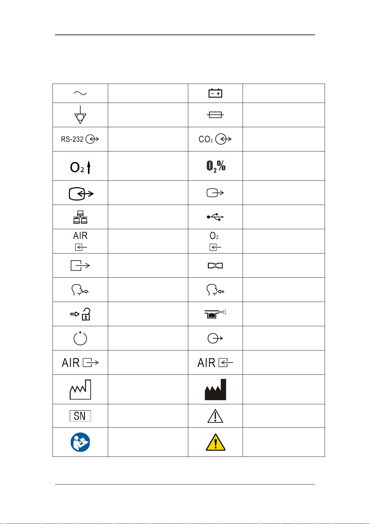
1.2 Equipment Symbols
Alternating current
Equipotential
RS-232 port
O2↑button
Video input/output
connection
Network connection
Air supply connection
Pneumatic outlet
Battery
Fuse
CO2/calibration connection
O2 sensor connector
VGA output connection
USB port
Oxygen supply connection
Flow sensor
Expiratory port
Unlock
Compressor status indicator
Compressed air outlet (of
the compressor)
Manufacture date
Serial number
Refer to instruction
manual/booklet
Inspiratory port
Nebulizer connection
Nurse call connection
Central pipeline gas supply
inlet (of the compressor)
Manufacturer
Caution
General warning sign
1-7
Page 22
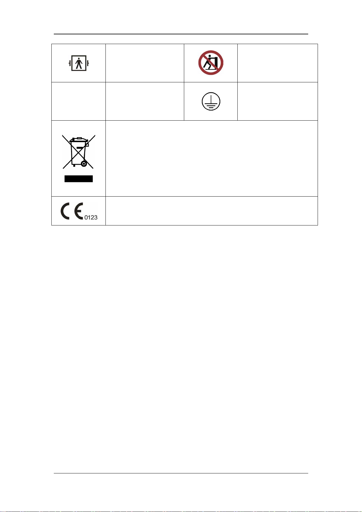
IP21
Type BF applied part.
Defibrillation-proof
protection against electric
shock.
IP21
Degrees of protection
provided by enclosure (IP
Code)
The following definition of the WEEE label applies to EU member states only.
This symbol indicates that this product should not be treated as household
waste. By ensuring that this product is disposed of correctly, you will help
prevent bringing potential negative consequences to the environment and
human health. For more detailed information with regard to returning and
recycling this product, please consult the distributor from whom you purchased
it.
* For system products, this label may be attached to the main unit only.
The product bears CE mark indicating its conformity with the provisions of the
Council Directive 93/42/EEC concerning medical devices and fulfils the
essential requirements of Annex I of this directive.
No pushing
Protective earth (ground)
1-8
Page 23

2 The Basics
2.1 System Description
2.1.1 Intended Use
The Ventilator is intended to provide ventilation assistance and breath support for adult,
pediatric and infant patients with respiratory insufficiency or respiratory failure in the
hospital or other medical institutions. Ventilation may be delivered via mask or tracheotomy.
This product must be operated by doctors, respiration therapist or other specially trained and
authorized personnel. Anyone unauthorized or untrained must not perform any operation on
it.
2.1.2 Contraindications
There are no absolute contraindications for this product. However, for some patients who
suffer from special diseases, special ventilation is required or treatment has to be carried out
before mechanical ventilation. Otherwise, hazards may be resulted.
2.1.3 Components
The ventilator consists of a main unit (including pneumatic circuit, electronic system,
mechanical structure, software, display, CO2 module), cart, support arm, air compressor, and
breathing hoses (refer to chapter 12 Accessories).
Connect the patient to the ventilator via the patient breathing circuit.
The applied part of the ventilator is breathing masks.
2-1
Page 24
2.2 Equipment Appearance
2.2.1 Front View
8
7
6
11
5
4
3
2
9
10
12
1
2-2
Page 25

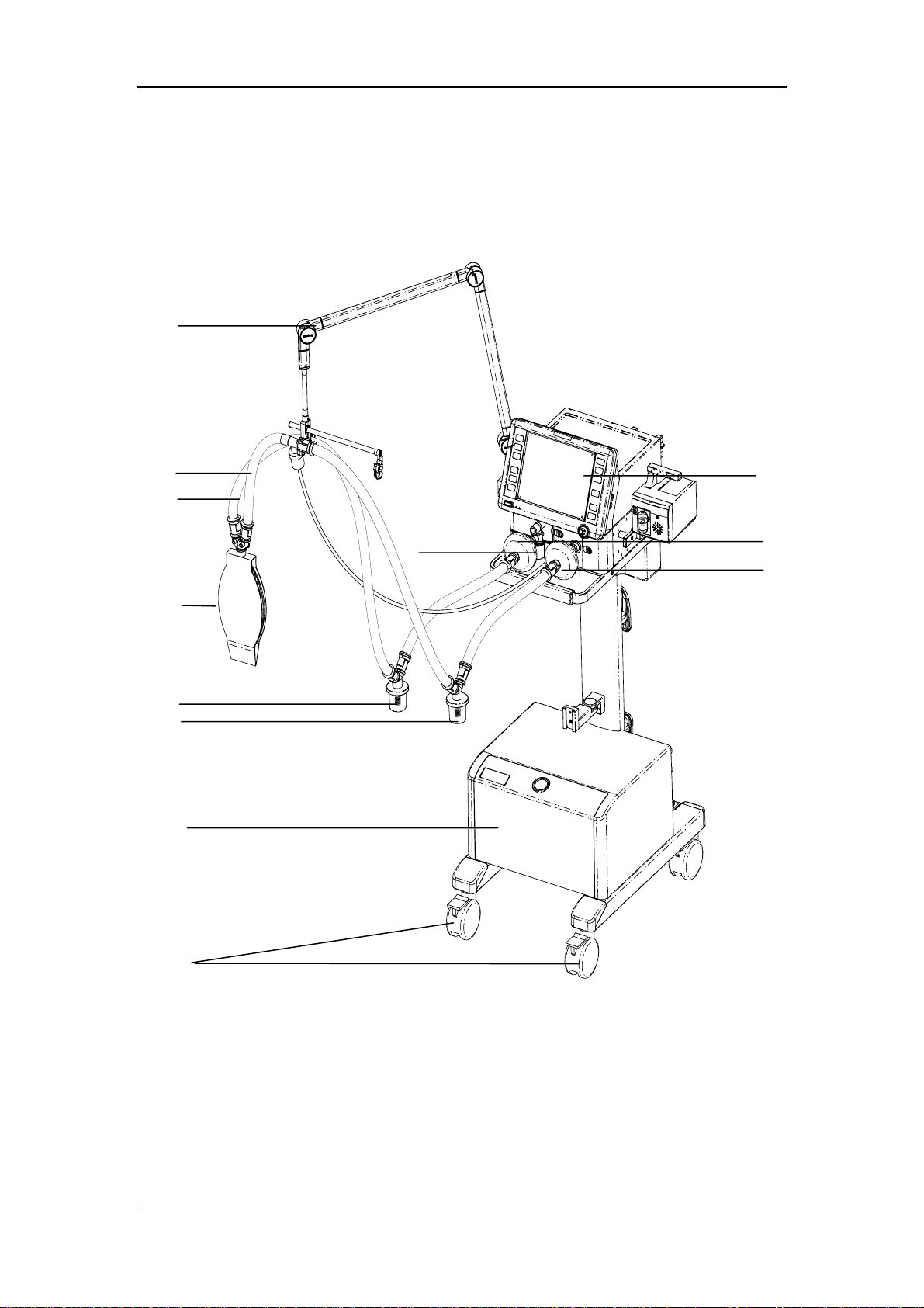
1. Caster and brake
The four casters of the ventilator have brakes.
2. Compressor
3. Inspiratory water trap
Collects condensed water in the hose.
4. Expiratory water trap
Collects condensed water in the hose.
5 Test lung
6. Expiratory hose
7. Inspiratory hose
8. Support arm
Supports the patient’s breathing hoses.
9. Display
10. Expiratory filter
Prevents water and bacteria inside the patient hoses from entering the ventilator’s
internal pneumatic circuit.
11. Water trap at the expiratory port
12. Inspiratory filter
Prevents water and bacteria inside the patient hoses from entering the ventilator’s
internal pneumatic circuit.
2-3
Page 26
2.2.2 Rear View
13
5
2
3
4
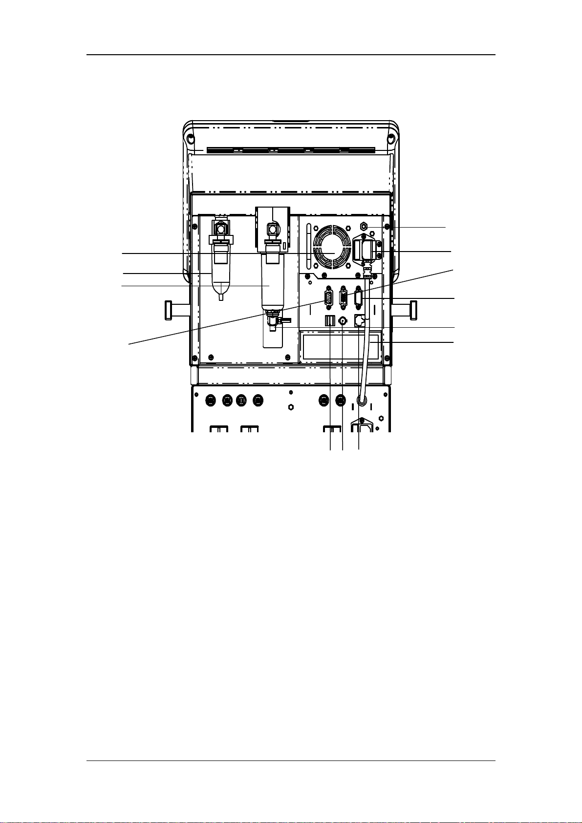
1. RS-232 port
Connects to the medical-grade external device via RS-232 protocol to implement the
communication between the ventilator and external device.
910
8
6
7
1
11
12
2. Oxygen supply connection (with filter water trap)
3. Air supply connection (with filter water trap)
4. CO2/calibration connection
One multiplex connector for calibrating inspiratory and expiratory flows and supplying
power for the external CO2 analyzer.
5. Fan
6. AC mains inlet
7. VGA connection
The ventilator provides a D-Sub 15, female video output connector, which connects to
an external display and outputs VGA visual signals same to the primary display. This
connection allows for interfacing to an externally located 24 bits, 800 x 600, SVGA
monitor, which should be a medical grade monitor.
2-4
Page 27

8. USB port
9. Network connection
One multiplex connector for network and software online upgrade.
10. Nurse call connection
Connects to the hospital’s calling system and outputs nurse call signals when an alarm
occurs.
11. Inspiratory dust filter
12. Fan filter (filter at air intake vent)
13. Equipotential stud / lug
Provides a ground point. Eliminates the ground potential difference between different
devices to ensure safety.
2.2.3 Air Compressor
The air compressor has standby function. In the standby mode, the compressor starts to
deliver compressed air to the ventilator automatically if the hospital central pipeline gas
supply fails. The compressor stops delivering compressed air automatically when the central
pipeline gas supply returns to normal.
1 2
1. Power indicator
4
3
56 7
8
The power indicator is lit when the compressor is connected to power supply and the
power switch is turned on.
2. Status indicator
The status indicator is lit when the central pipeline gas supply is applied.
3. Alarm indicator
The alarm indicator is lit when the compressor internal temperature is abnormally high.
In this case, the compressor may shut off at any time and stop delivering gas.
2-5
Page 28

4. Pressure gauge
The pressure gauge indicates the air pressure at the compressed air outlet.
5. Compressed air outlet
6. Central pipeline gas supply inlet
7. Power switch
8. Mains power inlet (with fixing pressure plate)
9. Air intake vent (with dust filter)
10. Hourmeter
The hourmeter indicates the accumulated running time of the compressor (not including
the accumulated running time when the central pipeline gas supply is applied)
NOTE
Burn-in is required for the compressor before delivery. The reading indicated by
the compressor hourmeter shall be less than 150 hours at the time of delivery.
2-6
Page 29
3 Installations and Connections
WARNING
Do not use antistatic or conductive masks or breathing hoses. They can cause burns
if they are used near high frequency electrosurgical equipment.
To ensure optimum performance of the ventilator, re-do system check each time
when accessories or components like hose, humidifier, and filter are replaced.
Adding accessories or other components to the ventilator can increase system
inspiratory and expiratory resistance.
3.1 Connect the Power Supply
3.1.1 Connect the System Power Supply
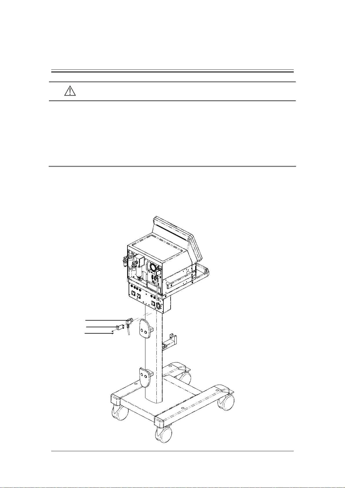
A
B
C
3-1
Page 30
A. AC power cord B. AC Power cord retainer C. Screw
1. Plug the AC power cord into the AC power outlet.
2. Place the AC power cord retainer above the power outlet and align the retainer with the
screw holes.
3. Tighten the two screws.
3.1.2 Connect the Main Unit Power Supply
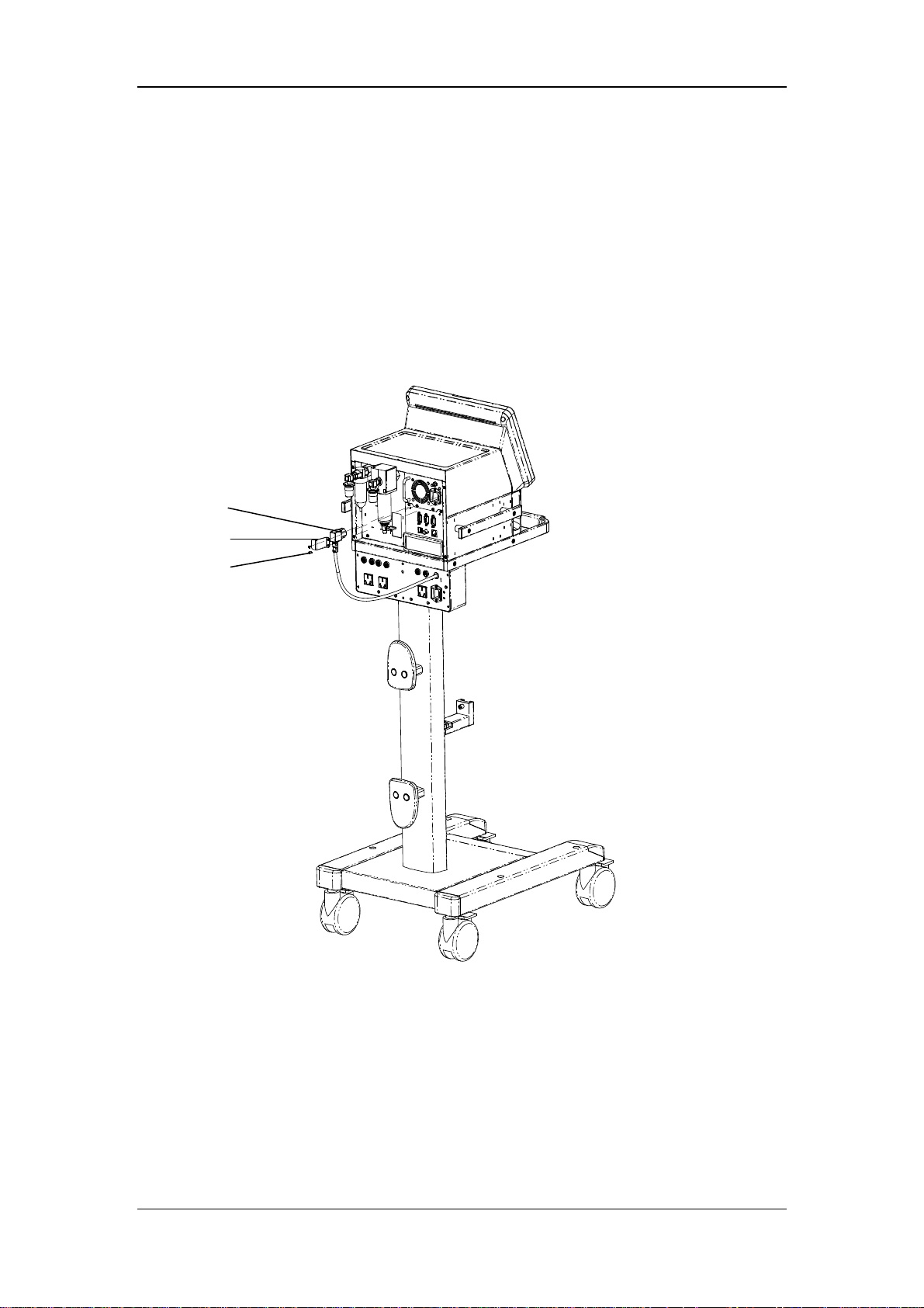
A. Main unit power cord B. Main unit power cord retainer C. Screw
1. Plug the main unit power cord into the power outlet.
2. Place the main unit power cord retainer above the power outlet and align the retainer
with the screw holes.
3. Tighten the two screws.
3-2
Page 31

3.1.3 Connect the Compressor Power Supply
B
A
A. Compressor B. Compressor power cord
Plug the compressor power cord into the auxiliary electrical outlet specially for compressor
directly.
3-3
Page 32

3.2 Connect the Gas Supply
A
B
C
A. Oxygen supply connection B. Air supply connection C. Compressor
The ventilator provides two supply gas connections: oxygen and air. The supply gas hoses are
differentiated by different colors. Do not attempt to switch oxygen and air supply connections.
Follow these steps to connect the oxygen and air supplies:
1. Check that the seals at the connectors are in good condition. If any damage is found, do
not use the hose. Replace the defective seal to avoid leakage.
2. Plug the supply hoses and connectors into the corresponding supply connections at the
rear of the ventilator.
3. Ensure that the supply hoses are properly connected. Screw the nut on the hose with
hand.
The oxygen supply connection is connected to the hospital’s central pipeline supply and the
air supply connection can be connected to either the hospital’s central pipeline supply or
compressor’s compressed air outlet.
3-4
Page 33

The ventilator works normally under supply pressure of 280 to 650 kPa. Supply pressure of
less than 280 kPa can impair the performance of the ventilator and even cease ventilation.
Supply pressure between 650 and 1000 kPa can impair the performance of the ventilator but
will not cause any hazard arising from high pressure gas.
3.3 Install the Support Arm
E
D
F
C
G
B
A
A. Fixing block knob B. Fixing block C. Hose hook
D. Support bar E. Support arm joint F. Support arm joint
G. Support arm joint
1. Loosen the fixing block knob. Place the fixing block onto the handle on the side of the
ventilator.
2. Tighten the fixing block knob.
3-5
Page 34

3. Adjust the support arm.
Support arm joint E or G: To adjust the bending angle of the support arm
downward, push and hold the blue button
one hand and hold the support bar and press it downward with the other hand.
Support arm joint E or G can be adjusted for up to 130°. To adjust the bending
angle of the support arm upward, only lift the support bar to the desired position
with no need to push the blue button
Support arm joint F: pull support arm joint F upward or downward to the desired
position.
Hold the bottom of support arm or the suport bar beside support arm joint G and
push it leftward or rightward with force to rotate the support arm to the desired
position.
4. Place the breathing hoses onto the hose hook.
on support arm joint E or G with
.
NOTE
Operate support arm joint E or G with both hands as shown below. Operate with
only one hand will bring some risk.
3-6
Page 35

3.4 Install the Water Traps
A
A. Water trap on the breathing hose
B. Water trap on the expiration valve assembly
Rotate to push in the water trap upward. Make sure that the water trap is installed in place.
B
3-7
Page 36

3.5 Install the Breathing Hoses
E
B
A
D
C
A. Inspiratory filter B. Expiratory filter
C. Inspiratory water trap D. Expiratory water trap
E. Support arm hook
1. Mount the filters onto the inspiratory and expiratory ports.
2. Connect the inspiratory filter to the water trap via the hose. Connect the other end of the
hose to the Y piece.
3. Connect the expiratory filter to the water trap via the hose. Connect the other end of the
hose to the Y piece.
4. Place the breathing hoses onto the support arm hook.
3-8
Page 37

3.6 Install the Humidifier
Note
The humidifier assembly and its installation steps described here are only for
reference.
3.6.1 Install the Humidifier onto the Ventilator
F
D
A. Humidifier B. Humidifier sliding wheel
C. Humidifier bracket fixed seat D. Screw
E. Humidifier inlet F. Humidifier outlet
E
A
B
C
3-9
Page 38

1. Align the humidifier sliding wheel with the humidifier bracket fixed seat and slide in the
humidifier.
2. Tighten the screw.
3. Mount the filters onto the inspiratory and expiratory ports.
4. Connect the inspiratory filter to the humidifier inlet via the hose.
5. Connect the humidifier outlet to the water trap via the hose. Then, connect the water trap
to the Y piece via the hose.
6. Connect the expiratory filter to the water trap via the hose. Then, connect the water trap
to the Y piece via the hose.
7. Place the breathing hoses onto the support arm hook.
The rated range of the ventilator breathing system (VBS):
Inspiratory and expiratory gas pathway resistance: 0~6cmH2O/ (L/s) at 60L/min
VBS compliance: 0~5ml/cmH2O
3-10
Page 39

3.6.2 Install the Humidifier onto the Pendant
A
B
C
G
F
A. Humidifier B. Knob for fixing block
C. Fixing block D. Humidifier sliding wheel
E. Humidifier bracket fixed seat F. Screw
G. Beam
1. Loosen the knob for fixing block. Put the fixing blocking onto the pendant beam.
2. Tighten the knob for fixing block.
D
E
3. Align the humidifier sliding wheel with the humidifier bracket fixed seat and slide in the
humidifier.
4. Tighten the screws.
5. Install the breathing hoses. For details, refer to steps 3 through 7 in 3.6.1.
3-11
Page 40

WARNING
When installing the humidifier, make sure that the humidifier connector shall be
lower than the ventilator’s breathing connectors and the patient when installing
the humidifier.
3.7 Install the Nebulizer
C
B
A. Nebulizer connector B. Nebulizer hose C. Nebulizer
A
1. Connect one end of the nebulizer hose to the nebulizer connector and the other end of
the hose to the nebulizer.
2. Mount the nebulizer onto the inspiratory hose via the hose.
3-12
Page 41

Note
The nebulizer assembly and its installation steps described here are only for
reference.
WARNING
Nebulization yields the best performance at flow of 6 L/min. Nebulizers with other
flows can create significant errors in tidal volume and oxygen mix.
3.8 Install the CO2 Module
D
B
A
E
C
F
G
A. Fastening screws for CO2 module mounting plate
B. CO2 module
C. Fastening screws for CO2 module
D. Water trap
E. Sampling line
3-13
Page 42

F. CO2/calibration connection
G. CO2 module connection line
1. Place the CO2 module mounting plate onto the ventilator’s handle. Then tighten the
fastening screws.
2. Place the CO2 module onto the mounting plate and align with the screw holes. Then
tighten the three fastening screws.
3. Connect the connection line at the back of the CO2 module to the ventilator’s
CO2/calibration connection.
4. Connect one end of the sampling line to the water trap and then mount the water trap
onto the CO2 module. Connect the other end of the sampling line to the patient.
3.9 Install the O2 Sensor
C
B
A
A. O2 sensor door B. O2 sensor C. O2 sensor connection line
1. Screw on the O2 sensor clockwise.
2. Plug in the O2 sensor connection line.
3. Buckle the O2 sensor door.
3-14
Page 43

4 User Interface
4.1 Display Controls
The control unit is characterized by the small number of operating elements. Its main
elements are:
4
3
1
2
1. Display (touch screen)
The display shows the software screen of the ventilator system. You can select and
change settings by touching the screen.
2. Fixed hard keys
The fixed hard keys are provided for rapid access to the ventilator’s major functions.
3. Alarm LED
The alarm LED indicates the priority of an active alarm by flashing different colors at
different frequencies.
4-1
Page 44

4. AC power LED and battery LED
indicates the AC power LED.
Lit: when the ventilator is connected to the AC power source.
Extinguished: when the ventilator is not connected to the AC power source.
indicates the battery LED.
Lit: when the battery is being charged or is already fully charged and the ventilator
is operating on AC power source.
Flash: when the ventilator is operating on battery power.
Extinguished: when the ventilator is not connected to the AC power source, or the
ventilator is not equipped with battery, or the ventilator battery is faulty.
4.1.1 Display
The ventilator display shows ventilation parameters, pressure/flow/volume waveforms and
spirometry loops etc.
The following is an example of waveforms screen. Display screen may vary subject to the
configurations.
1
2
3
4
5
6
8
12
11
10
7
9
4-2
Page 45

1. Ventilation mode field
Displays Standby or active ventilation mode, and ventilation assist.
2. NIV/ intubation icon field
Displays NIV when it is non-invasive ventilation, or intubation icon
invasive ventilation.
3. Mask/ ATRC and pipe diameter field
Displays mask icon
invasive ventilation and dynamic tube compensation is turned off, or ATRC and pipe
diameter when it is invasive ventilation and dynamic tube compensation is endotracheal
intubation or tracheotomy intubation.
4. Patient type/inspiratory trigger field
Indicates current patient type--adult (
prompt is displayed underneath the icon. The icon for inspiratory trigger is
is prompted for one second.
5. Alarm silence symbol and countdown field
Displays the time remaining in the 120s alarm silence period and alarm silence symbol
when it is non-invasive ventilation, or blank when it is
) or pediatric ( ). The corresponding text
when it is
, which
as well.
6. Alarm message field
Displays the active alarm message. When there are multiple alarm messages, the system
displays the symbol
[Current Alarm] menu which displays all current alarm messages, alarm occurrence
time, and alarm priority.
7. Prompt message field
Displays the active prompt message.
8. System time/battery
Displays current system time and battery status.
9. Parameter field
Displays measured parameters values of the ventilator.
10. Parameter setup quick key field
Displays ventilation setting parameters for the current mode of ventilation.
. Select the alarm message field at this moment to access the
4-3
Page 46

11. Ventilation mode setup field
Displays keys for setting ventilation mode.
12. Waveforms/spirometry/trends/measured values filed
Displays waveforms, spirometry loops, graphic trend, tabular trend, or measured values.
4.1.2 Fixed Hard Keys
14
13
12
11
10
9
8
1
2
3
4
5
6
7
1. Alarm Silence key
Push to silence alarm audio of an active alarm for 120 seconds. When 120 seconds
expires, the system exits alarm silenced status automatically and resumes alarm audio. If
a new alarm occurs during the alarm silenced period, the system exits alarm silenced
status automatically and gives alarm audio. In alarm silenced status, push this key to
clear alarm silence.
2. Alarm Reset key
When there are latched alarms, if the alarm conditions disappear, push to clear all
latched alarms.
4-4
Page 47

Latching alarms: the system continues displaying the alarm message even if the alarm
conditions end except that:
Alarm audio disappears;
Alarm LED stops flashing and is permanently lit with the same color;
Alarm message is displayed without background color;
The alarmed parameter measured value stops flashing.
3. Alarm Setup key
Push to access the alarm setup menu to set parameter alarm limits, alarm volume etc.
4. Standby key
Push to pop up a dialog box to confirm whether to enter Standby.
5. Freeze Key
Push to enter or cancel freeze status. For details, refer to 4.7
Freeze
.
6. Menu key
Push to open system main menu or close screen menu.
7. Control knob
Push the control knob to select a menu option or confirm your setting. Turn the control
knob clockwise or counterclockwise to scroll through the menu options or change your
settings.
8. System switch
Push and hold/push the system key to turn on/off the system.
9. Manual Breath Key
Push to deliver manual ventilation.
10. Exp. Hold key
In non-standby status, push and hold this key to allow the patient to remain in expiration
status and prevent the patient from inspiration. The screen shows [Exp. Hold Active].
Expiration Hold is active for a maximum of 30 seconds.
11. Insp. Hold key
In non-standby status, push and hold to allow the patient to remain in inspiration status
and prevent the patient from expiration. The screen shows [Insp. Hold Active].
Inspiration Hold is active for a maximum of 30 seconds.
12. Nebulizer key
Push to access nebulizer related menu and start nebulization after completing the
relevant settings. The LED in the upper left corner of this key is lit.
4-5
Page 48

13. O2↑key/suction
In non-standby status, push to start O2↑function and the LED in the upper left corner
of this key is lit. The screen shows the remaining O2↑ time. When O2↑is active, push
this key again to stop O2↑. During O2↑, removing the breathing hoses enters suction
screen.
14.
When pushed, the LED in the upper left corner of this key is lit and the ventilator enters
locked status. The prompt message field displays [Panel Locked. Push the Lock key to
unlock the panel]. During this period, only the Alarm Reset key, Alarm Silence key,
Manual Breath key, O2↑key, and key are enabled while the touchscreen and
other fixed hard keys are disabled. Push the
key again to unlock.
4.2 Waveforms Screen
Select [Waveforms] to access the waveforms screen as shown below.
4-6
Page 49

4.3 Spirometry Loops Screen
Select [Spirometry] to access the spirometry loops screen as shown below.
Spirometry loops reflect patient lungs function and ventilation condition as well, such as the
patient’s lungs compliance, over-inflation, breathing system leakage and airway blockage.
The system provides three types of spirometry loops: P-V (pressure-volume) loop, F-V
(flow-volume) loop, and F-P (flow-pressure) loop. The three types of loops come from
pressure, flow, and volume waveforms data.
Up to two types of spirometry loops are displayed at a time. To select the desired loop:
1. Select [Spirometry] on the main screen.
2. Select the desired loop to be displayed.
The ventilator provides the function of reference loop. Selecting [Save] saves the current F-V
loop, P-V loop, and F-P loop as reference loop and displays the time on which the reference
loop is saved. Selecting the time button views the reference loop saved at that time moment.
Selecting [Hide Ref.] hides the reference loop which is being displayed.
The ventilator saves reference loops at up to four time moments. If reference loops at four
time moments are already saved, when [Save] is selected again, the system automatically
4-7
Page 50

clears the oldest reference loops except the loops being viewed and saves the current loops as
reference loops.
4.4 Graphic Trend Screen
Graphic trend depicts the changes in parameter measured values in graphic form over a
specific period of time. Each point on the curved line represents the physiological parameter
value at each time moment.
You can access the following graphic window by selecting [Trends] and/or selecting the
button for switching between [Tabular] and [Graphic].
1
2
3
4
5
7
6
8
15
1. Graphic scale
2. Graphic trend
3. Event mark field, displaying event marks in the current trend window. Alarm events of
different priorities are represented by different mark colors. Red event mark indicates a
high priority alarm event and yellow a medium or low priority alarm event.
4. Time scale axis, displaying time scale information on the time axis.
13 11
12
4-8
10
9
Page 51

5. Cursor
6. Time field, displaying the time corresponding to the cursor.
7. Parameter area, displaying parameter values at the time corresponding to the cursor.
8. Vertical scroll bar, indicating the position of the currently displayed parameter in the
entire parameter sequencing.
9. Button for switching between graphic trend and tabular trend
10. Button for parameter grouping. Options are [All], [Pressure], [Volume], [Time] and
[Other]. [Pressure] parameters include Ppeak, Pplat, Pmean, and PEEP. [Volume]
parameters include TVi, TVe, TVe spn, MV, MVspn, and MVleak. [Time] parameters
include ftot, fmand, and fspn. [Other] parameters include Ri, Re, Cdyn, RSBI, WOB,
FiO2, FiCO2 and EtCO2.
11. Window time button, which can be set to 1h, 3h, 6h, 12h, 24h, 48h, and 72h.
12. Cursor control button for moving the cursor left or right.
13. Horizontal scroll bar control button for moving the horizontal scroll bar left or right.
14. Horizontal scroll bar, indicating the position of the currently displayed trend data in the
entire trend database.
15. Vertical scroll bar control button for moving the vertical scroll bar up and down.
4-9
Page 52

4.5 Tabular Trend Screen
Tabular trend depicts the changes in parameter measured values in tabular form over a
specific period of time.
You can access the following tabular window by selecting [Trends] and/or selecting the
button for switching between [Tabular] and [Graphic].
1
2
3
4
11
1. Event mark field, displaying event marks in the current trend window. Alarm events of
different priorities are represented by different mark colors. Red event mark indicates a
high priority alarm event and yellow a medium or low priority alarm event.
2. Time field, displaying the time corresponding to the cursor
3. Cursor column, displaying parameter values measured at the time corresponding to the
cursor. Alarm events of different priorities are represented by different background
colors. Red event mark indicates a high priority alarm event and yellow a medium or
low priority alarm event.
4. Vertical scroll bar, indicating the position of the currently displayed parameter in the
entire parameter sequencing.
5. Button for switching between graphic trend and tabular trend
10
9
4-10
587 6
Page 53

6. Button for parameter grouping. Options are [All], [Pressure], [Volume], [Time] and
[Other]. [Pressure] parameters include Ppeak, Pplat, Pmean, and PEEP. [Volume]
parameters include TVi, TVe, TVe spn, MV, MVspn, and MVleak. [Time] parameters
include ftot, fmand, and fspn. [Other] parameters include Ri, Re, Cdyn, RSBI, WOB,
FiO2, FiCO2 and EtCO2.
7. Resolution button, which can be set to 1 min, 5 min, 10 min, 15 min, 30 min, and 1h.
8. Horizontal scroll bar, indicating the position of the currently displayed trend data in the
entire trend database.
9. Cursor control button for moving the cursor left or right.
10. Horizontal scroll bar control button for moving the horizontal scroll bar left or right.
11. Vertical scroll bar control button for moving the vertical scroll bar up and down.
4.6 Measured Values Screen
Select [Va lu e s] to access the measured values screen as shown below.
4-11
Page 54

4.7 Freeze
The freeze function features to pause on-screen waveforms and spirometry loops refreshing
in real-time and review short-time patient data so that you can have a close examination of
the patient’s status within this time period.
Enter freeze status
In non-standby or non-freeze status, push the Freeze key and [Freeze Active. Push the
Freeze key to unfreeze] is prompted on the screen. The system enters freeze status. Cursors
appear on the waveforms and loops. All displayed waves and loops are frozen, namely, they
are not refreshed. The data in the parameter area are refreshed normally. In freeze status, the
Save button on the Spirometry Loops screen is disabled, and you cannot save a loop as
reference loop but can view an already saved reference loop.
View frozen waveforms
You can turn the control knob clockwise or counter clockwise to move the cursor to view the
frozen waveforms.
Cursor
4-12
Page 55

View frozen spirometry loops
You can turn the control knob clockwise or counter clockwise to move the cursor to view the
frozen spirometry loops.
Exit freeze status
In freeze status, push the Freeze key to exit the freeze status. In freeze status, if no operation
is performed on the ventilator for more than three (3) minutes, the system exits freeze status
automatically.
4-13
Page 56

FOR YOUR NOTES
4-14
Page 57

5 System Settings
5.1 Change Display Settings
5.1.1 Waveforms
1. Push the Menu key. Select [Display] and then [Waveforms].
2. Select the waveforms to be displayed.
3. Select [Draw Wave] and toggle between [Curve] and [Fill].
[Curve]: the waveform is displayed as a curved line.
[Fill]: the waveform is displayed as a filled area.
5.1.2 Spirometry Loops
1. Select [Spirometry].
2. Select the loops to be displayed.
5.1.3 Measured Values
On the waveforms, spirometry loops, or trends screen, the right side of the screen is divided
into three parameter areas which are Parameter Area 1, Parameter Area 2, and Parameter Area
3 from the top down. To change the parameters to be displayed in each parameter area:
1. Press the Menu key. Select [Display] and then select [Values].
2. Select the parameters to be displayed.
Parameter
Area 1
Parameter
Area 2
5-1
Parameter
Area 3
Page 58

5.1.4 Colors
To change the colors of waveforms, waveform related parameters, waveform related
spirometry loops, and waveform related alarm limits:
1. Push the Menu key. Select [Display] and then [Color].
2. Select the desired color. The colors of waveforms, waveform related parameters,
waveform related spirometry loops also change. Dark color of the selected color is
suggested for the color of waveform related alarm limits.
The following table lists the waveforms, waveform related parameters, waveform related
spirometry loops and waveform related alarm limits.
Waveform Waveform related parameters Waveform
related
spirometry loop
Paw Ppeak, Pmean, Pplat, PEEP, NIF, PEEPi,
P0.1
Flow MV, MVleak, MVspn, TVe, TVi, TVspn,
ftot, fmand, fspn, Vtrap
Volume / / /
/ FiO2 / FiO2
CO2 EtCO2, FiCO2 / EtCO2,
P-V loop, F-P loop Ppeak
F-V loop MV, TVe,
Waveform
related
alarm limits
ftot
FiCO2
Alarm limits
Waveform
5-2
Parameter
Page 59

5.2 Set Date and Time
1. Push the Menu key. Select [System] and then [Time].
2. Set the date and time.
3. Select [Date Format] and toggle between [YYYY-MM-DD], [MM-DD-YYYY] and
[DD-MM-YYYY].
4. Select [Time Format] and toggle between [24 h] and [12 h].
5.3 Change Language
1. Push the Menu key. Select → [Maintain] → [User] → enter the required password
→ [Setup] → [Language].
2. Select the desired language.
3. Restart the ventilator to activate the selected language.
5.4 Adjust Screen Brightness
1. Push the Menu key. Select [System] and then [Ventilator].
2. Select [LCD Brightness] and select the appropriate value (ranging from 1 to 10) for
screen brightness. The value 10 is for the brightest and 1 the least bright. If the ventilator
is battery powered, you can select a less bright screen to save battery capacity.
5.5 Adjust Key Volume
1. Push the Menu key. Select [System] and then [Ventilator].
2. Select [Key Volume] and select the appropriate value (ranging from 0 to 10) for key
volume. The value 0 is for audio off and 10 for the loudest.
5.6 Set Unit
5.6.1 Set Weight Unit
1. Push the Menu key. Select [System] and then [Unit].
2. Select [Weight Unit] and toggle between [kg] and [Ib].
5-3
Page 60

5.6.2 Set Paw Unit
1. Push the Menu key. Select [System] and then [Unit].
2. Select [Paw Unit] and toggle between [cmH2O], [hPa], and [mbar].
5.6.3 Set CO2 Unit
1. Push the Menu key. Select [System] and then [Unit].
2. Select [CO2 Unit] and toggle between [mmHg], [kPa], and [%].
5.7 Turning on/off O2% Monitoring
1. Push the Menu key. Select [System] and then [Ventilator].
2. Select [O2% Monitoring] and toggle between [ON] and [OFF]. When [ON] is selected,
oxygen concentration of patient’s inspired gas can be monitored. It needs about 30s after
powering on the ventilator till the point that the oxygen concentration monitoring
function enters full accuracy mode. You can set [O2% Monitoring] to [OFF] if oxygen
concentration monitoring function accompanying the ventilator is not needed. In this
case, [O2 Monitoring Off] is prompted on the screen.
5.8 Select Tinsp/I:E
1. Push the Menu key. Select [System] and then [Ventilator].
2. Select [Tinsp/I:E] and toggle between [Tinsp] and [I:E]. Based on your Tinsp/I:E
selection, corresponding Tinsp or I/E ventilation setting parameters are adopted for
V-A/C, P-A/C and PRVC modes.
5.9 Set TV/f Source
1. Push the Menu key. Select [System] and then [Ventilator].
2. Select [TV/f Source] and toggle among [Height&Gender], [IBW] and [Patient Type].
When the ventilator is used on a new patient, the system sets the default TV, f or fapnea
values based on the TV/f source setting.
5.10 Set Sigh
1. Push the Menu key. Select [System] and then [Ventilator].
2. Select [Sigh] and toggle between [TV] and [Δint.PEEP].
5-4
Page 61

5.11 Set IP Address
If your ventilator needs to upgrade the software, follow these steps to set the IP address:
1. Push the Menu key. Select [Maintain] → [User] → enter the required password →
[Setup] → [IP Address].
2. Set the IP address. IP address has four step boxes. The setting range of each of the box is
0 to 255.
5.12 Manage Configurations
The ventilator provides the following types of configurations:
Factory configuration, namely, factory preset configuration. There are factory default
adult configuration and factory default pediatric configuration based on patient type.
User configuration. You can change the ventilator’s settings based on the actual
requirement and save the changed settings as user configuration. There are user adult
configuration and user pediatric configuration based on patient type.
Latest configuration. In actual applications, you may change some settings, which,
however, may not be saved as user configuration. The ventilator stores these settings in
real time. The stored settings are the latest configuration.
5.12.1 Restore the Latest Configuration Automatically
When the ventilator is used on a same patient after powered on, the system adopts the latest
configuration automatically.
5.12.2 Set Power-on Default Configuration
The ventilator can be set to loading factory default configuration or user default configuration
of different patient categories. When the ventilator is used on a new patient, the ventilator
loads the set default configuration automatically.
1. Push the Menu key. Select [Maintain] → [User] → enter the required password →
[Config].
2. Set [Select Default Config].
5-5
Page 62

5.12.3 Save as User Configuration
You can change the ventilator’s settings based on the actual requirement and save the
changed settings as user configuration.
1. Push the Menu key. Select [Maintain] → [User] → enter the required password →
[Config].
2. If the current patient type is adult, select [Save as User Adu Config]. If the current
patient type is pediatric, select [Save as User Ped Config].
5.12.4 Load Configuration Manually
You can load configuration when necessary during the operation of the ventilator.
1. Push the Standby key. The system enters standby status after your confirmation.
2. Push the Menu key. Select [System] and then [Load Config].
3. Select your desired configuration.
5.13 View System Information
5.13.1 Version Information
Push the Menu key. Select [Syst. Info] and then [Ve rsions ]. You can view the version
information of system software.
5.13.2 Configuration Information
Push the Menu key. Select [Syst. Info.] and then [Config Info]. You can view the
configuration information of the ventilator such as ventilation mode.
5.13.3 System Check Results
Push the Menu key. Select [Syst. Info] and then [Syst. Check]. You can view the ventilator
system check information, including check items, check results, and check time.
5.13.4 Maintenance Information
Push the Menu key. Select [Syst. Info] and then [Maintain]. You can view total system
running time, system startup time, CO2 last calibration time, O2 sensor last calibration time,
and flow sensor last calibration time.
5-6
Page 63

5.14 Export
The ventilator’s export function means to export some data to USB memory.
5.14.1 Export Screen
Screen export means to export the last saved screen capture of the ventilator. The exported
file is in bmp format.
To export screenshot,
1. Insert the USB memory to the USB port of the ventilator.
2. Select the desired screen to be exported and then push the Freeze key to capture the
screen.
3. Push the Menu key. Select [Tool] → [Export] → [Export Screen]. The system
checks the availability of USB memory. If the USB memory is available and has
sufficient space, the system exports the last captured screen.
5.14.2 Export Data
Data export means to export the patient information, log, trend and other data of the ventilator.
The exported file is in html format.
To export data,
1. Insert the USB memory to the USB port of the ventilator.
2. Push the Menu key. Select [Tool] → [Export] → [Export Data]. The system checks
the availability of USB memory. If the USB memory is available and has sufficient
space, the system exports patient information, log, trend and other data.
5-7
Page 64

FOR YOUR NOTES
5-8
Page 65

6 Start Ventilation
6.1 Turn on the System
1. Plug the power cord into the AC power outlet. Make sure that the AC power LED is lit.
2. Push and hold the
3. The alarm LED flashes yellow and red once in turn and then the speaker and buzzer give
a self-test sound.
4. A start-up screen and self-test progress bar appear. Then the standby screen is displayed.
key.
6.2 Preoperative Test
6.2.1 AC Power and Battery Power Source Switch Test
1. Push the key to start the ventilator.
2. Remove AC power. Make sure that the AC power LED is extinguished, the battery
indicator flashes, and the low level alarm [Battery in Use] is triggered.
3. Reconnect AC power and operate the ventilator on AC mains. Make sure that the AC
power LED is lit, the battery indicator stops flashing and remains illuminated, and the
alarm [Battery in Use] disappears.
4. Push the
6.2.2 Pipeline Tests
key again to turn off the ventilator.
6.2.2.1 O2 Pipeline Test
1. Connect an O2 pipeline supply.
2. Connect the test splint lung.
3. Push the
4. Select adult ventilation mode and make the ventilator start ventilation. Make sure that
the ventilator ventilates properly.
5. Disconnect the O2 pipeline supply.
6. The high level alarm [O2 Supply Pressure Low] is triggered with the decrease in O2
pressure.
key to start the ventilator.
6-1
Page 66

6.2.2.2 Air Pipeline Test
1. Connect an air supply or air compressor gas supply.
2. Connect the test splint lung.
3. Push the
4. Select adult ventilation mode and make the ventilator start ventilation. Make sure that
the ventilator ventilates properly.
5. Disconnect the air pipeline supply or air compressor gas supply.
6. The high level alarm [Air Supply Pressure Low] is triggered with the decrease in air
pressure.
key to start the ventilator.
6.3 Power on Self-test
Power on self-tests include:
CPU self-test
Memory (RAM and ROM) selft test
Watchdog self-test
Analog/Digital (A/D) converter self-test
Temperature sensor self-test
Buzzer self-test
6.4 System Check
WARNING
To ensure optimum performance of the ventilator, re-do system check each time
when accessories or components like hose, humidifier, and filter are replaced.
Push the Standby key. Standby screen appears after your confirmation. The standby screen
displays the latest system check time. Select [Syst. Check]. Connect air and oxygen supplies
and block the patient wye as prompted. Select [Ok] to start system check item by item.
6-2
Page 67

System check items include:
O2 flow sensor test: test the O2 inspiratory valve and O2 flow sensor;
Air flow sensor test: test the Air inspiratory valve and Air flow sensor;
Expiratory flow sensor test;
Pressure sensor test: test the pressure sensors at the inspiratory and expiratory ports;
Expiration valve test;
Safety valve test;
O2 sensor test;
Leakage (mL/min);
Compliance (mL/cmH2O);
Circuit resistance (cmH2O/L/s).
System check result can be:
Pass: indicates that check of this item is completed and is passed;
Fail: indicates that check of this item is completed but is failed;
Cancel: indicates that check of this item is cancelled;
No Gas Supply: indicates that O2 or Air supply is not connected when O2 sensor test,
O2 or Air flow sensor test is being carried out;
Monitoring Off: indicates that the sensor monitoring function may not be turned on
when O2 sensor test is being carried out.
When system check is being performed, the system prompts [Running] on the right side of
the current check item. In this case, if you select [Skip], the system stops check of this item
immediately and displays [Cancel]. Check of the next item begins at the same time. If you
select [Stop], the system stops check of the current item and also check of the remaining
items, and displays [Cancel].
When checks of all items are completed, if you select [Retry], the system starts a new round
of check. When [Exit] is selected, the system exits check and enters standby screen.
6.5 Select Patient
After system check is completed, select [Exit] and then select a patient. If [Same Patient] is
selected, select [Vent Type] in the accessed menu and select [Ok]. If [New Patient] is
selected, set [Patient Type], [IBW], and [Vent Type] in the accessed menu, and select [Ok].
6-3
Page 68

6.6 Ventilation Type
The ventilator provides two ventilation types: invasive and non-invasive. Invasive ventilation
is the default ventilation type.
6.6.1 Invasive Ventilation
Invasive ventilation means to ventilate the patient through manual airway (endotracheal
intubation or tracheostomy). In invasive ventilation, all ventilation modes for adult and
pediatric patients are enabled. In invasive ventilation, ATRC function can be set.
The calculated leakage is compensated up to 80 % of the set tidal volume in invasive mode.
6.6.1.1 ATRC
ATRC refers to automatic tube resistance compensation function, which the ventilator can
adjust the input pressure to keep the pressure of the tube end and pressure set on the
ventilator to be the same as possible for endotracheal intubation or tracheotomy intubation of
the different tube diameters that the user chooses.
ATRC can be set on the parameter setting interfaces of each mode.
1. Select a ventilation mode, and select [ATRC] to enter the ATRC interface.
2. Set the intubation type, tube diameter and the proportion of compensation.
Intubation type: endotracheal intubation or tracheotomy intubation.
Tube diameter: the tube diameter of intubation.
Compensation proportion: the percentage of ATRC.
Compensation of expiration procedure : turn on or off the compensation of
expiration procedure.
3. Select [OK] to turn on the ATRC function. If ATRC function is turned on, select
[Disable ATRC] on the ATRC interface to stop the ATRC function of the ventilation
procedure immediately.
WARNING
ATRC function may induce autotriggering. If autotriggering occurs, first check the
patient, breathing circuit, and other settings as possible causes before lowering the
Compensate setting or disabling ATRC.
If intubation type and pipe diameter are set incorrectly, it may cause harm to
patients. Please set intubation type and pipe diameter correctly.
6-4
Page 69

6.6.2 NIV (non-invasive ventilation)
NIV, whose full name is non-invasive ventilation, means to ventilate the patient by using a
nasal mask or breathing face mask instead of by endotracheal intubation or tracheostomy.
In NIV, all ventilation modes for adult patients and pressure related ventilation modes for
pediatric patients are enabled. The disabled ventilation modes in NIV appear grey.
The calculated leakage is compensated up to 200% of the set tidal volume but not more than
2 L maximum in NIV mode.
6.6.3 Set Ventilation Type
To set up ventilation type:
1 If the ventilator is not in Standby, push the Standby key and select [Ok] from the pop-up
dialog box to enter Standby.
2. Select [Same Patient] or [New Patient] on the standby screen as required.
3. Set [Vent Type] to [Invasive] or [NIV] in the opened menu and then select [Ok].
4. Select [Start Ventilation] on the standby screen. If [NIV] is selected, the mark for
current mode + mask icon
screen, indicating that non-invasive ventilation is set up successfully.
+ NIV is displayed in the upper left corner of the
NOTE
NIV can be selected only in Standby.
6-5
Page 70

6.7 Ventilation Mode
NOTE
The ventilator creates negative pressure in the expiratory phase due to patient’s
active inspiration. There is no limit pressure for negative pressure in the expiratory
phase. Instant negative pressure is caused by patient’s active inspiration. In the
inspiratory phase, high pressure alarm limit is available. When high pressure
alarm limit is reached, the ventilator releases pressure immediately. Pressure in the
inspiratory phase is generated by the ventilator gas delivery.
The P-A/C and P-SIMV are the recommended ventilation modes for use with a
closed-suction catheter. And the settings are decided by the operator according to
the patient situation.
6.7.1 Ventilation Mode and Parameter Setup
1. Ventilation mode setup field
Displays keys for setting ventilation mode. Selecting
setting ventilation mode. The ventilator is configured with the following ventilation
modes: V-A/C, P-A/C, CPAP/PSV, V-SIMV, P-SIMV, PRVC, APRV and DuoLevel.
Your machine may have different ventilation modes.
2. Parameter setup quick key field
Displays ventilation setting parameters for the current mode of ventilation. Selecting
displays more ventilation setting parameters. The parameters of ATRC function
can be set here. Ventilation parameters vary subject to the ventilation mode.
displays more keys for
1
2
Follow these steps to set up ventilation modes:
1. In the ventilation mode setup filed, select the key to set the desired ventilation mode.
The accessed menu displays the ventilation parameters which can be set in the selected
ventilation mode.
2. Select the ventilation parameter to be set.
3. Push the control knob and turn it to set the selected parameter to the appropriate value.
4. Push the control knob to confirm the setting.
6-6
Page 71

5. Set other parameters in the same way.
6. Select [Ok] when parameter setup is completed.
Follow these steps to set up ventilation parameters:
1. In the parameter setup quick key field, select the ventilation parameter to be set.
2. Push the control knob and turn it to set the selected parameter to the appropriate value.
3. Push the control knob to confirm the setting.
4. Set other parameters in the same way.
6.7.2 Apnea Ventilation
Apnea ventilation is a reserve ventilation mode initiated when the ventilator detects patient
apnea in CPAP/PSV, V-SIMV, P-SIMV, APRV and DuoLevel modes.
Apnea ventilation can exit only when:
Patient’s spontaneous breathing has been detected for two continuous times,
Ventilation mode has been confirmed again,
Ventilation mode is swapped,
The Alarm Reset key is depressed,
Apnea ventilation is turned off.
Apnea ventilation the ventilator provides is manifested differently subject to the ventilation
mode for the purpose of matching the doctor’s ventilation strategy to the maximum.
In the SIMV mode, if patient apnea occurs, the ventilator ventilates the patient at the apnea
ventilation frequency in place of the previous SIMV frequency (while other parameter
settings are kept unchanged). During apnea ventilation, same to the previous SIMV mode, the
ventilator allows patient spontaneous breathing or trigger to support ventilation. In the SIMV
mode, apnea ventilation can be turned off by setting the apnea ventilation switch. When
apnea ventilation is turned off, the message “Apnea Vent Off” is displayed in the prompt
message field all the time.
In the CPAP/PSV or DuoLevel mode, if patient apnea occurs, the ventilator applies pressure
control ventilation at the preset apnea pressure and ensures that the actual breathing
frequency is not lower than the preset apnea ventilation frequency. During apnea ventilation,
the ventilator still allows patient spontaneous breathing or trigger to support ventilation. If
patient spontaneous breathing does not occur any longer, the actual breathing frequency is
equal to the preset apnea ventilation frequency.
6-7
Page 72

6.7.3 IntelliCycle
IntelliCycle intelligent synchronous technology means to adjust Exp% dynamically by
adaptive algorithm through extracting and analysing the feature of the waveforms when
Exp% is set to Auto in CPAP/PSV, V-SIMV, P-SIMV and DuoLevel modes. According to the
lung properties of the patient, it can adjust Exp% to the best value intelligently to improve the
synchronization between the patient and the device, make the patient more comfortable
during breathing, reduce the time to adjust the settings during treatment, and reduce the
workload of medical staffs and ensure the excellent synchronous effect at the same time.
6.7.4 V-A/C
V-A/C is volume-assist/control ventilation mode. In V-A/C, fixed tidal volume is delivered to
the patient at the inspiratory flow within the inspiration time. The airway pressure varies
according to the resistance and compliance of the patient’s lungs and thorax. When the
airway pressure reaches the preset pressure limit level, it is held at this level. Expiratory
phase is switched to and pressure is fully released only when the airway pressure exceeds the
pressure alarm high limit.
V-A/C supports synchronous trigger in expiratory phase. Namely, when the ventilator detects
patient inspiratory effort, it delivers next mechanical ventilation in advance.
The following figures show typical waveforms in V-A/C mode.
Paw
Pressure alarm high limit
Insp. trigger level
Flow
Insp. pause
Tinsp Texp
Pplat
Breathing cycle
Insp. flow
Plimit
PEEP
In V-A/C under non-NIV, you need to set the following ventilation parameters:
Time
Insp. trigger level
Time
1. [O2%]: Oxygen concentration
2. [TV]: Tidal volume
6-8
Page 73

3. [Tinsp] or [I:E]: Time of inspiration or ratio between the inspiratory and
expiratory time
4. [f]: Breathing frequency
5. [Flow]: Inspiratory flow
6 [Plimit]: Pressure limitation
7. [Assist]: Assisted spontaneous breathing
8. [F-Trig] or [P-Trig]: Assisted trigger
9. [PEEP]: Positive end-expiratory pressure
10. [△int.PEEP] or [Sigh]: Intermittent positive end-expiratory pressure
11. [ATRC]: Automatic tube resistance compensation
In V-A/C under NIV, you need to set the following ventilation parameters:
1. [O2%]: Oxygen concentration
2. [TV]: Tidal volume
3. [Tinsp] or [I:E]: Time of inspiration or ratio between the inspiratory and
expiratory time
4. [f]: Breathing frequency
5. [Flow]: Inspiratory flow
6 [Plimit]: Pressure limitation
7. [Assist]: Assisted spontaneous breathing
8. [F-Trig] or [P-Trig]: Assisted trigger
9. [PEEP]: Positive end-expiratory pressure
10. [△int.PEEP] or [Sigh]: Intermittent positive end-expiratory pressure
6-9
Page 74

6.7.5 P-A/C
P-A/C is pressure-assist/control ventilation mode. In P-A/C, the airway pressure rises to the
preset inspiratory pressure level within the Time of pressure rising and is held at this level
until inspiration time is expired. Then expiration is switched to. When the airway pressure is
held at the preset inspiratory pressure level, delivered gas flow changes with the resistance
and compliance of the patient’s lungs. During the inspiratory phase, when the delivered
volume exceeds the tidal volume high alarm limit, the system switches to expiratory phase
immediately. During the expiratory phase, synchronous trigger is supported. Specifically,
next mechanical ventilation can be delivered in advance when patient inspiratory effort is
detected.
The following figures show typical waveforms in P-A/C mode.
Paw
Tslope
Insp. pressure
PEEP
Flow
Tinsp
Insp. trigger level
Insp. trigger level
TV exceeds the limit
Time
Time
In P-A/C under non-NIV, you need to set the following ventilation parameters:
1. [O2%]: Oxygen concentration
2. [Pinsp]: Pressure control level of inspiration
3. [Tinsp] or [I:E]: Time of inspiration or ratio between the inspiratory and
expiratory time
4. [f]: Breathing frequency
5. [Tslope]: Time of pressure rising
6 [PEEP]: Positive end-expiratory pressure
7. [Assist]: Assisted trigger
8. [F-Trig] or [P-Trig]: Inspiration trigger level
9. [ATRC]: Automatic tube resistance compensation
6-10
Page 75

In P-A/C under NIV, you need to set the following ventilation parameters:
1. [O2%]: Oxygen concentration
2. [Pinsp]: Pressure control level of inspiration
3. [Tinsp] or [I:E]: Time of inspiration or ratio between the inspiratory and
expiratory time
4. [f]: Breathing frequency
5. [Tslope]: Time of pressure rising
6 [PEEP]: Positive end-expiratory pressure
7. [Assist]: Assisted trigger
8. [F-Trig] or [P-Trig]: Inspiration trigger level
6.7.6 CPAP/PSV
PSV, pressure support ventilation, is a pressure mode. The system delivers a PSV when it
detects that patient inspiratory effort reaches the preset inspiration trigger level. Time of
pressure rising and pressure support level are set by the user. At the beginning of inspiratory
phase, patient airway pressure rises to the preset pressure level within the preset Time of
pressure rising and is held at this pressure level until patient inspiratory flow is detected to
reach the expiration trigger level. In PSV, when the airway pressure is held at the preset
pressure level, delivered gas flow changes with the resistance and compliance of the patient’s
lungs.
Paw
Flow
PSV
Insp. trigger
△Psupp
Exp. trigger
Insp. trigger
Apnea ventilation
Tslope
△Papnea
Time
Time
Apnea time
I:E=1:2
Apnea vent cycle
6-11
Page 76

In CPAP (continuous positive airway pressure ventilation), the airway pressure is held at the
user-set positive pressure level throughout the ventilation cycle. The patient breathes
spontaneously and determines his own breath rate, tidal volume, and breath time. The system
starts apnea ventilation when detecting that the period of time when patient does not perform
continuous spontaneous breathing exceeds the preset apnea time.
Paw
Flow
Spontaneous breathing Apnea ventilation
PEEP
Tslope
Apnea time
I:E=1:2
Apnea vent cycle
In CPAP/PSV under non-NIV, you need to set the following ventilation parameters:
1. [O2%]: Oxygen concentration
△Papnea
Time
Time
2. [Tslope]: Time of pressure rising
3. [△Psupp]: Pressure support level
4 [PEEP]: Positive end-expiratory pressure
5. [Exp%]: Expiration trigger level
6. [ΔPapnea]: Pressure of apnea ventilation
7. [fapnea]: Frequency of apnea ventilation
8. [F-Trig] or [P-Trig]: Inspiration trigger level
9. [ATRC]: Automatic tube resistance compensation
In CPAP/PSV under NIV, you need to set the following ventilation parameters:
1. [O2%]: Oxygen concentration
2. [Tslope]: Time of pressure rising
3. [△Psupp]: Pressure support level
4 [PEEP]: Positive end-expiratory pressure
6-12
Page 77

r
5. [Exp%]: Expiration trigger level
6. [ΔPapnea]: Pressure of apnea ventilation
7. [fapnea]: Frequency of apnea ventilation
8. [Tinsp]: Inspiration time
9. [F-Trig] or [P-Trig]: Inspiration trigger level
6.7.7 V-SIMV and P-SIMV
SIMV is designed to guarantee minimum ventilation frequency. Volume control ventilation or
pressure control ventilation in SIMV mode is delivered within the trigger window and is
delivered automatically at the end of the trigger window if not triggered within the trigger
window. Outside the trigger window, spontaneous breathing is supported.
The following figures show typical waveforms in V-SIMV+PSV and P-SIMV+PSVmodes.
V-SIMV+PSV
Paw
5 s
Trigger
window
SIMV cycle
Volume
control
5 s
Trigger
window
Volume
control
SIMV cycle
5 s
Trigger
window
Flow
△Psupp
Insp. trigge
Time
Time
6-13
Page 78

P
-
SIMV+PSV
Trigger
window
SIMV cycle
Pressure
control
5 s
Trigger
window
?Psupp
Insp. trigger
Paw
Flow
SIMV cycle
5 s 5 s
Trigger
window
Pressure
control
In V-SIMV under non-NIV, you need to set the following ventilation parameters:
Time
Time
1. [O2%]: Oxygen concentration
2. [TV]: Tidal volume
3. [Tinsp]: Time of inspiration
4. [fSIMV]: Frequency of SIMV
5. [Flow]: Inspiratory flow
6 [Plimit]: Pressure limitation
7 [PEEP]: Positive end-expiratory pressure
8. [Exp%]: Expiration trigger level
9. [△Psupp]: Pressure support level
10. [Tslope]: Time of pressure rising
11. [F-Trig] or [P-Trig]: Inspiration trigger level
12. [fapnea]: Frequency of apnea ventilation
13. [Apnea Vent]: Apnea ventilation switch
14. [ATRC]: Automatic tube resistance compensation
In V-SIMV under NIV, you need to set the following ventilation parameters:
1. [O2%]: Oxygen concentration
2. [TV]: Tidal volume
3. [Tinsp]: Time of inspiration
6-14
Page 79

4. [fSIMV]: Frequency of SIMV
5. [Flow]: Inspiratory flow
6 [Plimit]: Pressure limitation
7 [PEEP]: Positive end-expiratory pressure
8. [Exp%]: Expiration trigger level
9. [△Psupp]: Pressure support level
10. [Tslope]: Time of pressure rising
11. [F-Trig] or [P-Trig]: Inspiration trigger level
12. [fapnea]: Frequency of apnea ventilation
13. [Apnea Vent]: Apnea ventilation switch
In P-SIMV under non-NIV, you need to set the following ventilation parameters:
1. [O2%]: Oxygen concentration
2. [Pinsp]: Pressure control level of inspiration
3. [Tinsp]: Time of inspiration
4. [fSIMV]: Frequency of SIMV
5. [Tslope]: Time of pressure rising
6 [PEEP]: Positive end-expiratory pressure
7. [Exp%]: Expiration trigger level
8. [△Psupp]: Pressure support level
9. [fapnea]: Frequency of apnea ventilation
10. [F-Trig] or [P-Trig]: Inspiration trigger level
11. [Apnea Vent]: Apnea ventilation switch
12. [ATRC]: Automatic tube resistance compensation
In P-SIMV under NIV, you need to set the following ventilation parameters:
1. [O2%]: Oxygen concentration
2. [Pinsp]: Pressure control level of inspiration
3. [Tinsp]: Time of inspiration
4. [fSIMV]: Frequency of SIMV
5. [Tslope]: Time of pressure rising
6 [PEEP]: Positive end-expiratory pressure
7. [Exp%]: Expiration trigger level
6-15
Page 80

8. [△Psupp]: Pressure support level
9. [fapnea]: Frequency of apnea ventilation
10. [F-Trig] or [P-Trig]: Inspiration trigger level
11. [Apnea Vent]: Apnea ventilation switch
6.7.8 PRVC
PRVC implements volume control by way of pressure control ventilation. In PRVC, a
relatively low pressure level is held as much as possible during the inspiratory phase and the
gas volume delivered is guaranteed to be equal to the set tidal volume. Pinsp will vary
according to the tidal volume setting and resistance and compliance of the patient’s lungs.
The ventilator adjusts Pinsp each time at a maximum increment of 3 cmH2O and the
maximum pressure does not exceed the pressure high alarm limit -5 cmH2O.
The first PRVC delivered is experimental ventilation mode for the purpose of calculating
compliance and resistance of the system and patient’s lungs based on which pressure level is
acquired. This pressure level will then be used for tidal volume control in the subsequent
ventilation cycles.
The following figures show typical waveforms in PRVC mode.
Experimental
Paw
ventilation
↑Differential pressure≤3
cmH2O
Paw≤alarm high limit-5cmH2O
Flow
Volume limit Reduce control pressure
In PRVC under non-NIV, you need to set the following ventilation parameters:
1. [O2%]: Oxygen concentration
2. [TV]: Tidal volume
3. [Tinsp] or [I:E]: Time of inspiration or ratio between the inspiratory and
expiratory time
4. [f]: Breathing frequency
6-16
Time
Time
Page 81

5. [Tslope]: Time of pressure rising
6 [PEEP]: Positive end-expiratory pressure
7. [Assist]: Assisted trigger
8. [F-Trig] or [P-Trig]: Inspiration trigger level
9. [ATRC]: Automatic tube resistance compensation
In PRVC under NIV, you need to set the following ventilation parameters:
1. [O2%]: Oxygen concentration
2. [TV]: Tidal volume
3. [Tinsp] or [I:E]: Time of inspiration or ratio between the inspiratory and
expiratory time
4. [f]: Breathing frequency
5. [Tslope]: Time of pressure rising
6 [PEEP]: Positive end-expiratory pressure
7. [Assist]: Assisted trigger
8. [F-Trig] or [P-Trig]: Inspiration trigger level
6.7.9 DuoLevel
DuoLevel is double level positive airway pressure ventilation. In DuoLevel, the ventilator
delivers positive airway pressure at two pressure levels alternatively during mechanical
ventilation or spontaneous breathing. The patient can breathe spontaneously at either pressure
level. During the low pressure phase, pressure support can be set. Trigger window is available
during both high and low pressure phases. The trigger window during the low pressure phase
is the later 5 seconds of low pressure time (Tlow) while the trigger window during the high
pressure phase is the later 1/4 of high pressure time (Thigh). Within the trigger window of
low pressure phase, inspiratory trigger transforms to high pressure gas delivery. Within the
trigger window of high pressure phase, expiratory trigger transforms to low pressure gas
delivery.
6-17
Page 82

The following figure shows typical waveform in DuoLevel mode.
Paw
Thigh
5s
Trigger
window
Phigh
Tlow
PSV
5s
Trigger
window
¼
Thigh
Trigger
window
Tslope
Insp. trigger
Exp.trigger
In DuoLevel under non-NIV, you need to set the following ventilation parameters:
1. [O2%]: Oxygen concentration
2. [Phigh]: High pressure
3. [Thigh]: Time of high pressure
4. [Plow]: Low pressure
5. [Tlow]: Time of low pressure
6. [Tslope]: Time of pressure rising
7. [Exp%]: Expiration trigger level
8. [△Psupp]: Pressure support level
9. [ΔPapnea]: Pressure of apnea ventilation
Plow
Time
10. [fapnea]: Frequency of apnea ventilation
11. [F-Trig] or [P-Trig]: Inspiration trigger level
12. [ATRC]: Automatic tube resistance compensation
In DuoLevel under NIV, you need to set the following ventilation parameters:
1. [O2%]: Oxygen concentration
2. [Phigh]: High pressure
3. [Thigh]: Time of high pressure
4. [Plow]: Low pressure
5. [Tlow]: Time of low pressure
6. [Tslope]: Time of pressure rising
7. [Exp%]: Expiration trigger level
6-18
Page 83

8. [△Psupp]: Pressure support level
9. [ΔPapnea]: Pressure of apnea ventilation
10. [fapnea]: Frequency of apnea ventilation
11. [F-Trig] or [P-Trig]: Inspiration trigger level
12. [ATRC]: Automatic tube resistance compensation
6.7.10 APRV
APRV is airway pressure release ventilation. It can be seen as periodical, short period airway
pressure release in CPAP mode.
The following figure shows typical waveform in APRV.
Paw
Thigh
Tslope
Tlow
Phigh
Plow
In APRV under non-NIV, you need to set the following ventilation parameters:
1. [O2%]: Oxygen concentration
2. [Phigh]: High pressure
3. [Thigh]: Time of high pressure
4. [Plow]: Low pressure
5. [Tlow]: Time of low pressure
6. [Tslope]: Time of pressure rising
Time
7. [ΔPapnea]: Pressure of apnea ventilation
8. [fapnea]: Frequency of apnea ventilation
9. [ATRC]: Automatic tube resistance compensation
6-19
Page 84

In APRV under NIV, you need to set the following ventilation parameters:
1. [O2%]: Oxygen concentration
2. [Phigh]: High pressure
3. [Thigh]: Time of high pressure
4. [Plow]: Low pressure
5. [Tlow]: Time of low pressure
6. [Tslope]: Time of pressure rising
7. [ΔPapnea]: Pressure of apnea ventilation
8. [fapnea]: Frequency of apnea ventilation
6.8 Change Alarm Limits
You can change the alarm limits for Paw, MV, ftot and TVe by pushing the Alarm Setup key
and selecting [Alarm Limits]. You can change the alarm limits for EtCO2 if your ventilator
is configured with CO2 module. You can also change alarm volume, apnea time, and
disconnection time. For details, refer to 9 Alarms..
6.9 Ventilate the Patient
WARNING
Before use on the patient, check that the oxygen concentration in the delivered gas
is consistent with the set value.
Select [Start Ventilation] when in Standby and the system begins to ventilate the patient
according to your settings.
6-20
Page 85

6.10 Ventilation Parameters Monitoring
WARNING
As required by the relevant rules and regulations, oxygen concentration should be
monitored when the equipment is used on the patient. If your ventilator is not
configured with such monitoring function or this function is turned off, use a
monitor which complies with the relevant international rules and regulations for
oxygen concentration monitoring.
NOTE
All the parameter values are calculated based on the real-time flow and pressure
waveforms data. For real-time flow and pressure data, five-point moving average
filter (FIR low pass filter) is adopted at original sampling rate of 250 Hz with about
24 Hz of cutoff frequency (3 db) and 10 ms of delay.
The conditions to which the tidal volume and minute volume the ventilator displays
correspond are temperature, ambient pressure, and saturated water vapor status.
Setting
parameter
TV The gas volume the patient inspires or expires each time during resting breathing.
O2% The volume percentage of oxygen in the mixed gas delivered to the patient.
Flow The gas delivered flow that the ventilator will use during the inspiratory phase.
I:E The ratio between the inspiratory and expiratory time.
PEEP Positive end-expiratory pressure.
Phigh Available only in DuoLevel mode. Phigh is the high pressure level at which the
Pinsp Inspiratory pressure in pressure control mode. It is an absolute value.
ΔPapnea Available only in CPAP/PSV, APRV and DuoLevel modes. ΔPapnea is
Description
patient can spontaneously breathe and is an absolute value.
inspiratory pressure in apnea ventilation mode and is relative to PEEP or Plow.
Plimit The pressure limit level at which the airway pressure is held during the inspiratory
phase until the start of expiratory phase.
Plow Available only in APRV, DuoLevel mode. Plow is the low pressure level at which
the patient can breathe spontaneously.
ΔPsupp The pressure support level in pressure support mode and is relative to PEEP or
Plow.
6-21
Page 86

Tslope Controls pressure rise slope in pressure mode.
f The number of mechanically controlled breaths delivered to the patient in one
minute.
fapnea Breathing frequency set in apnea ventilation mode.
fSIMV Breathing frequency set in SIMV mode.
Thigh Available only in APRV, DuoLevel mode. Thigh is the time that the ventilator
will hold the high pressure level.
Tlow Available only in APRV, DuoLevel mode. Tlow is the time that the ventilator will
hold the low pressure level.
Tinsp Time of inspiration in one breathing cycle.
F-Trig/P-Trig Pressure trigger and flow trigger included. When the trigger level is detected, the
ventilator starts to enter the inspiratory phase. When F-Trig is active, at the late
stage of exhalation the ventilator delivers a base flow from the inspiratory limb to
the expiratory limb. The base flow is essential for flow trigger. The ventilator
adjusts base flow from 2 to 20 L/min automatically to maintain PEEP and
establish baseline for patient triggering.
Δint.PEEP Available only in V-A/C mode. It indicates the positive end expiratory pressure
added in the sigh cycle, and is relative to PEEP.
Exp% Inspiratory termination level. The ventilator is switched to the expiratory phase
when the inspiratory flow drops to peak flow*Exp%. When the value of Exp% is
set to Auto, the IntelliCycle function is turned on.
Assist This parameter is available in V-A/C, PRVC and P-A/C modes to turn on or turn
off the assisted trigger function. When this function is turned on, the patient is
allowed to trigger mechanical ventilation at the end of expiration.
ATRC This parameter is available in all the ventilation modes except NIV to set
intubation type, tube diameter, compensation proportion.
Monitored
parameter
Ppeak The maximum pressure value in one breathing cycle.
Pplat The airway pressure during inspiratory pause.
Pmean The mean pressure value in one breathing cycle.
Description
PEEP Positive end-expiratory pressure.
TVi The inspired tidal volume in one cycle.
TVe The expired tidal volume in one cycle.
TVe/IBW The expired tidal volume in one cycle per IBW.
TVe spn The spontaneous expired tidal volume in one cycle.
MV The accumulated expired tidal volume in one minute.
6-22
Page 87

MVspn The accumulated spontaneous expired tidal volume in one minute.
The accumulated leakage (inspiratory volume minus expiratory volume) in one
MVleak
ftot The accumulated number of breaths in one minute.
fmand The accumulated number of mandatory breaths in one minute.
fspn The accumulated number of spontaneous breaths in one minute.
Ri The airway resistance during inspiration.
Re The airway resistance during expiration.
Cstat The static compliance.
Cdyn The dynamic compliance.
RSBI Rapid shallow breath index that is defined as fspn/TVespn.
WOB Work of breath.
NIF Negative inspiratory force.
P0.1
minute.
The pressure drop in the first 100 ms when the patient starts spontaneous
breathing.
Intrinsic PEEP(The PEEPi value displayed has already included PEEP value and
PEEPi
Vtrap The volume of trap gas in the lungs produced by intrinsic PEEP.
FiO2 The percentage of oxygen in the patient’s inspired gas.
EtCO2 The concentration of CO2 measured at the end of expiration.
FiCO2 The minimum CO2 concentration measured during inspiration.
is the actual airway pressure).
6.11 Enter Standby
Push the Standby key. Standby screen appears after your confirmation.
6-23
Page 88

6.12 Turn the System off
Push the key to turn the system off when in Standby. In non-Standby, push the
key and the system prompts [Please enter Standby mode to shut down the system.]. Select
[Ok] to close the dialog. The system is still in non- Standby.
6-24
Page 89

7 CO2 Monitoring
7.1 Introduction
CO2 monitoring is a continuous, non-invasive technique for determining the concentration of
CO2 in the patient’s airway by measuring the absorption of infrared (IR) light of specific
wavelengths. The CO2 has its own absorption characteristic and the amount of light passing
the gas probe depends on the concentration of the measured CO2. When a specific band of IR
light is passed through respiratory gas samples, some of IR light will be absorbed by the CO2
molecules. The amount of IR light transmitted after it has been passed through the respiratory
gas sample is measured with a photodetector. From the amount of IR light measured, the
concentration of CO2 is calculated. End tidal CO2 concentration reading is using the highest
values respectively of the temporal CO2-curve.
The measurement provides:
1. CO2 waveform;
2. End-tidal CO2 (EtCO2) value: the CO2 value measured at the end of the expiration
phase;
3. Fraction of inspired CO2 (FiCO2): the CO2 value measured during inspiration.
The rated respiration rate range of etCO2 module is 0 to 120 bpm, and the data sample rate is
50 Hz. The method used to determine the rated respiration rate range: Utilize a valve to
permit switching between the two sampling gases at different frequencies (simulating the
range of specified breath rates).Record the etCO2 value presented for each frequency. From a
diagram of end-tidal value over frequency, the frequency at which the gas analyzer is no
longer able to resolve etCO2 according to specification is identified.
7-1
Page 90

NOTE
As required by the relevant rules and regulations, carbon dioxide concentration
should be monitored when the equipment is used on the patient. If your ventilator
is not configured with such monitoring function, use a monitor which complies
with the relevant international rules and regulations for carbon dioxide
concentration monitoring.
7.2 Prepare to Measure CO2
1. Attach the water trap to the water trap fixer and then connect the CO2 components as
shown below.
Water trap fixer
Sampling line
Water trap
2. By default, the CO2 module is in measure mode. When the CO2 module is connected,
the [CO2 Startup] message is displayed on the screen.
3. After start-up is finished, the [CO2 Warmup] message is displayed. The CO2 module is
in ISO accuracy mode. If you perform CO
measurement accuracy may be compromised.
measurements during warm-up, the
2
4. After warm-up is finished, the CO2 module enters full accuracy mode.
It needs about 2 minutes after powering on the ventilator till the point that the CO2 module
enters full accuracy mode.
7-2
Page 91

NOTE
To extend the lifetime of the water trap and CO2 module, disconnect the water
trap and set the working mode of the module to standby when CO2 monitoring is
not required.
The CO2 measurement can be used, with specified accessories, with intubated and
non-intubated adult, pediatric. With patients, a sample of the respiratory gas is
drawn from the patient's breathing circuit through an airway adapter and a gas
sampling line.
CAUTION
The water trap collects water drops condensed in the sampling line and therefore
prevents them from entering the module. If the collected water reaches a certain
amount, you should drain it to avoid blocking the airway. Dispose of accumulated
fluids in accordance with the hospital policy or your local regulations.
The water trap has a filter preventing bacterium, vapor and patient secretions
from entering the module. After a long-term use, dust or other substances may
compromise the performance of the filter or even block the airway. In this case,
replace the water trap. Replacing the water trap once a month is recommended.
Or, replace the water trap when it is detected leaky, damaged or contaminated.
7.3 Make CO2 Settings
Connect the CO2 module to the ventilator. Push the Menu key. Select [System] and then
[CO2]. You can make CO2 settings as described below.
7-3
Page 92

7.3.1 Set Working Mode
The default working mode of the CO2 module is [Measure] when the ventilator is turned on
for the first time. If the current CO2 module is Standby, push the Menu key. Select [System]
and then [CO2]. Set [Wor king Mode] to [Measure] to start the CO2 module. When the
ventilator restarts, the CO2 module automatically continues with the previously selected
working mode.
When Standby, the working components of the CO2 module such as gas pump and infrared
light source are automatically turned off to extend the service life of the module.
7.3.2 Set Pump Rate
You can set patient [Pump Rate] to either [100 mL/min] or [70 mL/min].
The pump rate tolerance:15% or 15 ml/min, whichever is greater.
During normal use (37 °C, 100% RH), the maximum emptying interval during normal use
(sample gas 37 °C, 100% RH) for adult and pediatric use: 45 h@70 ml/min, 21 h@150
ml/min.
WARNING
Take the patient’s actual bearing capability into consideration and select the
appropriate pump rate when setting the pump rate.
7.3.3 Set Unit
1. Push the Menu key. Select [System] and then [Unit].
2. Select [CO2 Unit] and toggle between [mmHg], [kPa], and [%].
7-4
Page 93

7.3.4 Set Humidity Compensation
The CO2 module is configured to compensate CO2 readings for either Body Temperature and
Pressure, Saturated Gas (BTPS), to account for humidity in the patient’s breath, or Ambient
Temperature and Pressure, Dry Gas (ATPD).
100/%)()(
1. ATPD:
22 ambco
PvolCOmmHgP
2. BTPS:
P
where,
2CO
= partial pressure,
22
%vol
PvolCOmmHgP
ambCO
= CO2 concentration,
100/)47(%)()(
P
amb
= ambient pressure, and
unit is mmHg.
For CO2 module, humidity compensation is switched on or off based on the actual situations.
1. Push the Menu key. Select [System] and then [CO2].
2. Set [Humidity Comp] to [ON] or [OFF] in either BTPS or ATPD.
7.3.5 Restore Defaults
Push the Menu key. Select [System] and then [CO2]. Select [Defaults] to restore all menu
options to the factory default configurations.
7.3.6 Set CO2 Waveform
Refer to 5.1.1 W aveforms to set CO2 waveform..
7.4 Measurement Limitations
Measurement accuracy may be compromised due to:
Leakage or internal leakage of the sample gas
Mechanical shock
Cyclic pressure which is greater than 10 kPa (100 cmH2O)
Other interference source (if available)
Measurement accuracy may be affected by the breath rate and I/E ratio as follow:
etCO2 is within specification for breath rate ≤ 60 bpm and I/E ratio ≤ 1:1;
etCO2 is within specification for breath rate ≤ 30 bpm and I/E ratio ≤ 2:1.
Measurement accuracy is unspecified for breath rate larger than 60 bpm.
7-5
Page 94

7.5 Troubleshooting
When the sampling system of the CO2 module works incorrectly, check if the sampling line
is kinked. If not, remove the sampling line from the water trap. Then, if a prompt message
indicating airway malfunction appears on the screen, it means that the water trap is occluded.
In this case, you must replace the water trap. If no such prompt message is displayed, it
means that the sampling line is occluded. Then you must replace the sampling line.
7.6 Zero the Sensor
Zeroing the sensor aims to eliminate the effect of baseline drift on the readings during the
measurement so as to ensure measurement accuracy.
For CO2 module, a zero calibration is carried out automatically when necessary. You can also
start a manual zero calibration when deemed necessary. To manually start a zero calibration,
push the Menu key. Select [System] → [CO2] → [Zero]. You do not need to disconnect
the sensor from the breathing system when performing the zeroing.
7.7 Calibrate the Sensor
For CO2 module, a calibration should be performed once a year or when the measured value
has a great deviation. For details, refer to 11 Maintenance.
7-6
Page 95

8 Special Functions
8.1 Manual Breath
Push the Manual Breath key and the ventilator system delivers one breath to the patient in
accordance with the current ventilation mode.
NOTE
Pressing the Manual Breath key during inspiratory phase cannot initiate a manual
breath.
Manual breath function is disabled in CPAP mode and is supported when apnea
ventilation occurs.
Manual breath is disabled in standby status.
8.2 Expiration Hold
Expiration Hold means to extend the patient’s time of expiratory phase manually and to
prevent the patient from inspiration for a certain period of time.
Push and hold the Exp. Hold key. The ventilator starts the Expiration Hold function and the
screen shows [Exp. Hold Active]. Release the Exp. Hold key. The ventilator terminates the
Expiration Hold function. Expiration Hold is active for a maximum of 30 seconds. If the Exp.
Hold key is pushed and held for more than 30 seconds or is released, the ventilator terminates
the Expiration Hold function automatically.
During Expiration Hold, the ventilator calculates PEEPi automatically and displays the
calculation results in the box as shown below.
NOTE
There is at least one inspiratory phase between two expiration holds.
The system responds to Exp. Hold key pressing operation only in non-standby
status.
Expiration Hold function is disabled in CPAP mode and is supported when apnea
ventilation occurs.
8-1
Page 96

8.3 Inspiration Hold
Inspiration Hold means to extend the patient’s time of inspiratory phase manually and to
prevent the patient from expiration for a certain period of time.
Push and hold the Insp. Hold key. The ventilator starts the Inspiration Hold function and the
screen shows [Insp. Hold Active]. Release the Insp. Hold key. The ventilator terminates the
Inspiration Hold function. Inspiration Hold is active for a maximum of 30 seconds. If the Insp.
Hold key is pushed and held for more than 30 seconds, the ventilator terminates the
Inspiration Hold function automatically.
During Inspiration Hold, the ventilator calculates Cstat and Pplat automatically and displays
the calculation results in the box as shown below.
NOTE
There is at least one expiratory phase between two inspiration holds.
The system responds to Insp. Hold key pressing operation only in non-standby
status.
Inspiration Hold function is disabled in CPAP mode and is supported when apnea
ventilation occurs.
8.4 Nebulizer
During nebulization, aerosolized medicament is inhaled by the patient for the purpose of
therapy.
Push the Nebulizer key and set the appropriate nebulization time. Select [Ok] to start
nebulization. When the nebulizer is started up, the nebulizer indicator lamp is illuminated and
the screen prompt message filed displays the remaining nebulization time.
When the set nebulization time expires or the Nebulizer key is pushed again, the ventilator
terminates nebulization.
NOTE
CO2 cannot be measured in the aerosolized medicament environment. CO2 module
sampling and monitoring are suspended when the nebulizer is started.
Nebulization is disabled in V-A/C, V-SIMV and PRVC modes when patient type is
pediatric.
Aerosolized medication may occlude the expiration valve and flow sensor. Please
have them checked and cleaned after nebulization.
8-2
Page 97

NOTE
Nebulization may cause fluctuation in the patient’s FiO2.
8.5 O2↑
The O2↑function means to deliver oxygen with concentration higher than the normal level.
When the O2↑key is pushed, the ventilator starts the O2↑ function. The O2↑indicator
lamp is illuminated and the screen prompt message filed displays the remaining O2↑ time.
O2↑ is active for a maximum of two minutes. When O2↑ is functioning, the [O2%]
parameter in the parameter setup quick key field displays the currently set oxygen
concentration.
When two minutes of O2↑ expires or the O2↑key is pushed again, the ventilator
terminates O2↑ function. Removing the breathing hoses during O2↑starts the suction
function.
NOTE
When O2 supply pressure is low, this function is not initiated, and is terminated
automatically if this function is initiated already.
8.6 Suction
The ventilator provides a suction procedure to help the patient to complete suction.
1. Push the Menu key and select [Procedure].
2. Select [Suction] to access the suction procedure screen and activate the suction function.
When the suction procedure is activated, the system performs O2↑function and
prompts [O2↑ Active. Please disconnect the patient after adequate O2 is
delivered.]. If the patient hoses are not disconnected within the specified time, the
suction procedure will end automatically.
After the patient hoses are disconnected, the system prompts [The patient is
disconnected. Please reconnect the patient after suction is completed.] and
stops ventilating the patient. In this case, manual sunction can be applied to the
patient.
After manual suction applied to the patient, re-connect the patient hoses. The
system performs O2↑function and prompts [O2↑Active. The patient is
reconnected.].
To stop an active suction procedure during O2↑, select [Exit] or push the O2↑key.
8-3
Page 98

8.7 P0.1
P0.1 is the pressure drop within the first 100 ms after a patient starts spontaneous breathing.
1. Push the Menu key. Select [Tool] and select [Procedure].
2. Select [P0.1] to access the P0.1 measure screen.
3. Select [Start]. The system starts P0.1 measurement and prompts [Measurement
Active].
4. After the measurement is completed, the measurement result is displayed. The ventilator
can display the last three measurement results.
5. After the measurement is completed, waveforms and spirometry data are frozen
automatically.
NOTE
During P0.1 measurement, pushing the Freeze key does not produce freezing
operation.
If no operation is performed on P0.1 measurement screen within three minutes, the
measurement screen exits automatically.
8.8 NIF
NIF is the maximum negative pressure generated by the patient’s spontaneous breathing
within a period of time.
1. Push the Menu key. Select [Tool] and select [Procedure].
2. Select [NIF] to access the NIF measure screen.
3. Push and hold the [Press and Hold] button on the screen or the Exp. Hold key on the
display. The system starts NIF measurement.
4. Release the [Press and Hold] button or the Exp. Hold key. The measurement is
completed. The measurement result is displayed. The ventilator can display the last three
measurement results.
NOTE
During NIF measurement, pushing the Freeze key does not produce freezing
operation.
If no operation is performed on NIF measurement screen within three minutes, the
measurement screen exits automatically.
8-4
Page 99

8.9 PEEPi
The PEEPi measure function supports measurement of two parameters—PEEPi and Vtrap.
PEEPi is the positive end-expiratory pressure produced by the trapped gas and Vtrap is the
trapped gas volume.
1. Push the Menu key. Select [Tool] and select [Procedure].
2. Select [PEEPi] to access the PEEPi measure screen.
3. Select [Start]. The system starts PEEPi measurement and prompts [Measurement
Active].
4. After the measurement is completed, the measurement result is displayed. The ventilator
can display the last three measurement results.
5. After the measurement is completed, waveforms and spirometry data are frozen
automatically.
8.10 P-V Tool
Mechanical ventilation set with the optimal PEEP can improve oxygenation, improve
alveolar mechanics and reduce injury to the lungs. By drawing static pressure-volume curve
(static P-V loop), P-V tool is the method to determine the optimal PEEP based on the
characteristic points on the static P-V curve. The doctor is able to determine the optimal
PEEP for the patient with the help of this function. After the P-V tool function is enabled,
PEEP is first adjusted to be equal to the set Pstart. Then gas is delivered at constant flow and
expiration is performed at constant flow. Inspiration trigger is forbidden during ventilation.
When static P-V loop measurement is completed, ventilation is restored automatically with
the previous vent mode and parameters.
8-5
Page 100

The typical ventilation curves with static P-V tool function are shown below:
Pressure
Pmax
PEEP
adjusted to
Pstart
PEEP
Flow
Gas delivered
at constant flow
The typical static P-V loop is as shown below:
Turning point in
Volume
expiration
branch
Insp. time
Exp. time
Expiration
at constant
flow
Upper turning point
in inspiration
branch
Time
Time
Lower turning point
in inspiration branch
0
Pstart
Pressure
8-6
 Loading...