

Page 1

SV300/350 Ventilator
Service Manual
Page 2

Page 3

Intellectual Property Statement
SHENZHEN MINDRAY BIO-MEDICAL ELECTRONICS CO., LTD. (hereinafter called
Mindray) owns the intellectual property rights to this product and this manual. This manual
may refer to information protected by copyrights or patents and does not convey any license
under the patent rights of Mindray, nor the rights of others. Mindray does not assume any
liability arising out of any infringements of patents or other rights of third parties.
Mindray intends to maintain the contents of this manual as confidential information.
Disclosure of the information in this manual in any manner whatsoever without the written
permission of Mindray is strictly forbidden. Release, amendment, reproduction, distribution,
rent, adaption and translation of this manual in any manner whatsoever without the written
permission of Mindray is strictly forbidden.
、 and are the registered trademarks or trademarks owned by
Mindray in China and other countries. All other trademarks that appear in this manual are
used only for editorial purposes without the intention of improperly using them. They are the
property of their respective owners.
Contents of this manual are subject to changes without prior notice.
Revision History
This manual has a revision number. This revision number changes whenever the manual is
updated due to software or technical specification change. Contents of this manual are subject
to change without prior notice. Revision 1.0 is the initial release of the document.
Rev
Release time:
© Copyright 2
reserved.
ision number: 5.0
2
021-08
014-2021 Shenzhen Mindray Bio-Medical Electronics Co., Ltd. All rights
I
Page 4

Preface
Manual Purpose
This manual provides detailed information about the assembling, dissembling, testing and
troubleshooting of the equipment to support effective troubleshooting and repair. It is not
intended to be a comprehensive, in-depth explanation of the product architecture or technical
implementation. Observance of the manual is a prerequisite for proper equipment
maintenance and prevents equipment damage and personal injury.
This manual is based on the maximum configuration. Therefore, some contents may not
apply to your monitor. If you have any question, please contact our Customer Service
Department.
Intended Audience
This manual is geared for biomedical engineers, authorized technicians or service
representatives responsible for troubleshooting, repairing and maintaining the ventilator
machines.
Password
A password is required to access different modes within the ventilator machine.
User maintenance: 1234
Factory maintenance: 1118
II
Page 5

Table of Contents
1 Safety ................................................................................................................................. 1-1
1.1 Safety Information .......................................................................................................... 1-1
1.1.1 Dangers .............................................................................................................. 1-2
1.1.2 Warnings ............................................................................................................ 1-2
1.1.3 Cautions ............................................................................................................. 1-5
1.1.4 Notes .................................................................................................................. 1-7
1.2 Equipment Symbols ........................................................................................................ 1-7
2 Theory of Operation ........................................................................................................ 2-1
2.1 Pneumatic Circuit ............................................................................................................ 2-1
2.1.1 Overview of the Pneumatic System ................................................................... 2-1
2.1.2 Pneumatic Circuit Diagram ................................................................................ 2-2
2.1.3 Theory of Operation of the Pneumatic Subsystem ............................................. 2-5
2.2 Electrical Circuit ........................................................................................................... 2-19
2.2.1 Overview of the Hardware Boards ................................................................... 2-19
2.2.2 Electrical Circuit Diagram ............................................................................... 2-21
2.2.3 Power Supply System ...................................................................................... 2-22
2.2.4 Board Function ................................................................................................. 2-24
3 Checkout and Test ............................................................................................................ 3-1
3.1 System Inspection ........................................................................................................... 3-1
3.2 Power Failure Alarm Test (External Power and Buzzer) ................................................ 3-1
3.3 O2 Pipeline Test .............................................................................................................. 3-2
3.4 System Test ..................................................................................................................... 3-2
3.5 Spontaneous Breathing Test ............................................................................................ 3-3
3.6 Humidifier Performance Test .......................................................................................... 3-3
3.7 Alarm Tests...................................................................................................................... 3-3
3.7.1 Prepare for Alarm Tests ...................................................................................... 3-3
3.7.2 Battery in Use Alarm Test .................................................................................. 3-3
3.7.3 Power Failure Alarm Test ................................................................................... 3-4
3.7.4 Paw Too High Alarm Test .................................................................................. 3-4
3.7.5 TVe Too High Alarm Test ................................................................................... 3-4
3.7.6 TVe Too Low Alarm Test ................................................................................... 3-4
3.7.7 MV Too High Alarm Test ................................................................................... 3-4
3.7.8 MV Too Low Alarm Test ................................................................................... 3-5
3.7.9 PEEP Too Low Alarm Test ................................................................................. 3-5
3.7.10 Airway Obstructed Alarm Test ......................................................................... 3-5
3.7.11 Apnea Alarm Test ............................................................................................. 3-5
Test ............................................................................... 3-5
3.7.12 ftotal Too High Alarm
3.7.13 FiO2 Too High Alarm Test ............................................................................... 3-6
3.7.14 FiO2 Too Low Alarm Test ................................................................................ 3-6
1
Page 6

3.7.15 EtCO2 Too High Alarm Test ............................................................................ 3-6
3.7.16 EtCO2 Too Low Alarm Test ............................................................................. 3-6
3.7.17 SpO2 Too High Alarm Test .............................................................................. 3-7
3.7.18 SpO2 Too Low Alarm Test ............................................................................... 3-7
3.7.19 PR Too High Alarm Test .................................................................................. 3-7
3.7.20 PR Too Low Alarm Test ................................................................................... 3-7
3.8 Function Tests ................................................................................................................. 3-8
3.8.1 Checking the Standard Working Mode .............................................................. 3-8
3.8.2 Checking the Tidal Volume ................................................................................ 3-8
3.8.3 Checking the Trigger Function ........................................................................... 3-8
3.8.4 Checking Spontaneous Breathing in CPAP/PSV Mode ..................................... 3-8
3.8.5 Sidestream CO2 Test and Calibration ................................................................ 3-8
3.8.6 Mainstream CO2 Test ....................................................................................... 3-10
3.8.7 SpO2 Test .......................................................................................................... 3-11
3.8.8 Checking the Special Functions ........................................................................ 3-11
3.9 Electrical Safety Inspection ........................................................................................... 3-12
3.9.1 Electrical Safety Inspection Test ...................................................................... 3-12
3.9.2 Electrical Safety Inspection Form .................................................................... 3-13
4 Maintenance Menu and Software Upgrade ................................................................... 4-1
4.1 User Maintenance ........................................................................................................... 4-1
4.1.1 Overview ............................................................................................................ 4-1
4.1.2 Setting ................................................................................................................ 4-1
4.1.3 Defaults Settings ................................................................................................ 4-2
4.1.4 Data Transfer ...................................................................................................... 4-2
4.1.5 Interface Setting ................................................................................................. 4-4
4.1.6 System Information ............................................................................................ 4-5
4.1.7 CO2 Maintenance ............................................................................................... 4-6
4.2 Factory Maintenance ....................................................................................................... 4-7
4.2.1 Overview ............................................................................................................ 4-7
4.2.2 Factory Setup ..................................................................................................... 4-7
4.2.3 Factory Calibration ........................................................................................... 4-13
4.2.4 Calibration Data ............................................................................................... 4-14
4.2.5 Data Monitoring ............................................................................................... 4-15
4.2.6 Diagnosis Test .................................................................................................. 4-16
4.2.7 Event Logbook ................................................................................................. 4-17
4.3 Software Upgrade and Software Function Activation ................................................... 4-18
4.3.1 Network Upgrade ............................................................................................. 4-18
4.3.2 USB Memory Upgrade .................................................................................... 4-28
4.3.3 Function Activation .......................................................................................... 4-31
4.3.4 Func
tion Trial ................................................................................................... 4-35
5 Maintenance and Calibration ......................................................................................... 5-1
5.1 Equipment Maintenance.................................................................................................. 5-1
2
Page 7

5.1.1 One-year Replaceable Parts ............................................................................... 5-2
5.1.2 Periodically-Maintained Parts ............................................................................ 5-5
5.2 System Test ..................................................................................................................... 5-6
5.2.1 System Check ..................................................................................................... 5-7
5.2.2 Check the Mechanical Ventilation State ............................................................. 5-9
5.2.3 Check the Correctness of Sensor Zero Point ..................................................... 5-11
5.2.4 Check the Accuracy of Flow Sensor ................................................................ 5-12
5.2.5 Check the Accuracy of Pressure Sensor ........................................................... 5-13
5.3 System Calibration ........................................................................................................ 5-15
5.3.1 Flow Calibration (User) ................................................................................... 5-19
5.3.2 Flow Calibration (Factory) ............................................................................... 5-20
5.3.3 O2% Calibration (User) ................................................................................... 5-24
5.3.4 O2% Calibration (Factory) ............................................................................... 5-25
5.3.5 Mainstream CO2 Zeroing (User) ..................................................................... 5-26
5.3.6 Sidestream CO2 Zeroing (User) ....................................................................... 5-27
5.3.7 Sidestream CO2 Calibration (User) ................................................................. 5-27
5.3.8 Pressure and Flow Zeroing (User) ................................................................... 5-28
5.3.9 Pressure and Flow Zeroing (Factory) ............................................................... 5-29
5.3.10 Pressure Calibration (Factory) ....................................................................... 5-32
5.3.11 Expiratory Valve Calibration (Factory) .......................................................... 5-45
5.3.12 Air and O2 Calibration (Factory) ................................................................... 5-48
6 Troubleshooting ................................................................................................................ 6-1
6.1 Introduction ..................................................................................................................... 6-1
6.2 Troubleshoot System Check Failures .............................................................................. 6-1
6.3 Technical Alarms and Diagnosis ..................................................................................... 6-4
6.3.1 Main Board Related Technical Alarms............................................................... 6-4
6.3.2 Keyboard Related Technical Alarms .................................................................. 6-5
6.3.3 VCM Related Technical Alarms ......................................................................... 6-5
6.3.4 Auxiliary Monitor Board Related Technical Alarms .......................................... 6-9
6.3.5 Power Board Related Technical Alarms ........................................................... 6-10
6.3.6 CO2 Related Technical Alarms ......................................................................... 6-11
6.3.7 SpO2 Related Technical Alarms ....................................................................... 6-12
6.4 Failure Code Table ........................................................................................................ 6-13
6.5 Error Information .......................................................................................................... 6-18
6.6 Diagnostic Test .............................................................................................................. 6-19
6.6.1 Pre
6.6.2 Correspondence between the Sensors & Valves on the Valve Test Screen and the
Components .............................................................................................................. 6-19
6.6.3 Troubleshooting Methods by Using Valve Test Tool ....................................... 6-21
6.7 Pneumatic System Failures ........................................................................................... 6-25
6.7.1 Commonly Used Devices and Tools ................................................................ 6-25
6.7.2 Pneumatic Failures List .................................................................................... 6-26
6.7.3 Gas Supply Subsystem ..................................................................................... 6-29
parations before Using the Valve Test Tool ................................................. 6-19
3
Page 8

6.7.4 Blower Fan and Flow Control Subsystem ........................................................ 6-33
6.7.5 Safety Valve Assembly ..................................................................................... 6-36
6.7.6 Expiration Valve Assembly .............................................................................. 6-38
6.7.7 O2 Sensor Has Great Measurement Error ........................................................ 6-40
6.8 Hardware and Electrical System Failures ..................................................................... 6-41
7 Repair and Disassembly .................................................................................................. 7-1
7.1 Prepare for Disassembly ................................................................................................. 7-2
7.1.1 Tools ................................................................................................................... 7-2
7.1.2 Preparations ........................................................................................................ 7-2
7.2 Disassemble the Service Parts ......................................................................................... 7-3
7.2.1 Remove the Lithium Battery .............................................................................. 7-3
7.2.2 Replace the O2 Sensor ....................................................................................... 7-4
7.2.3 Remove the HEPA Filter and Fan Dust Screen .................................................. 7-4
7.2.4 Remove the Main Unit Dust Screen ................................................................... 7-5
7.2.5 Remove the Disinfectable Expiratory Valve Assembly and Safety Valve
Detachable Part ........................................................................................................... 7-6
7.2.6 Remove the Expiratory Valve Diaphragm and Expiratory Check Valve ............ 7-7
7.2.7 Remove the Parts of the Disinfectable Part of the Safety Valve ........................ 7-7
7.2.8 Remove the Upper Housing Assembly .............................................................. 7-8
7.2.9 Remove the Speaker ........................................................................................... 7-9
7.2.10 Remove the WIFI Module (Optional) .............................................................. 7-9
7.2.11 Remove the SpO2 Module (optional)............................................................... 7-9
7.2.12 Remove the Display Assembly ...................................................................... 7-10
7.2.13 Remove the Main Unit Front Housing ........................................................... 7-10
7.2.14 Remove the Monitoring Board Assembly ....................................................... 7-11
7.2.15 Remove the Display Rear Housing and Key Control Board .......................... 7-12
7.2.16 Remove the Alarm Light Board ..................................................................... 7-13
7.2.17 Remove the Display Assembly ...................................................................... 7-14
7.2.18 Remove the Touchscreen ............................................................................... 7-14
7.2.19 Remove the Encoder ...................................................................................... 7-15
7.2.20 Replace the Pressure Sensor Filter ................................................................. 7-15
7.2.21 Remove the Safety Valve Seat Assembly ....................................................... 7-16
7.2.22 Remove the Electromagnet ............................................................................ 7-17
7.2.23 Remove the Air Flow Sensor ......................................................................... 7-17
7.2.24 Remove the Sensor Adapter Board ................................................................ 7-17
7.2.25 Remove the O2 Sensor Seat Assembly .......................................................... 7-18
7.2.26 Remove the Kernel Assembly ........................................................................ 7-18
7.2.27 Remove the AC-DC Power Board ................................................................. 7-20
7.2.28 Remove the DC-DC Power Board ................................................................. 7-21
7.2.29 Remove the Fan.............................................................................................. 7-22
7.2.30 Remove the AC Power Socket ....................................................................... 7-22
7.2.31 Remove the DC Input Socket ......................................................................... 7-23
7.2.32 Remove the Expiratory Valve Seat Assembly ................................................ 7-24
4
Page 9

7.2.33 Remove the Expiratory Valve Voice Coil Motor ............................................ 7-24
7.2.34 Remove the Sidestream CO2 Module (optional) ........................................... 7-24
7.2.35 Remove the Blower Box Assembly ............................................................... 7-25
7.2.36 Remove the Vacuum Sensor Board ................................................................ 7-27
7.2.37 Remove the Inspiratory Valve Assembly ....................................................... 7-28
7.2.38 Remove the Filter Net for Inspiratory Valve .................................................. 7-29
7.2.39 Remove the O2 Inlet Assembly ...................................................................... 7-29
7.2.40 Remove the Proportional Valve and Nebulizer Valve .................................... 7-31
7.2.41 Remove the Pressure Regulator Assembly ..................................................... 7-32
7.2.42 Remove the O2 Flow Sensor .......................................................................... 7-33
7.2.43 Remove the Low Pressure O2 Connector ...................................................... 7-34
7.2.44 Remove the Battery Adapter Board ............................................................... 7-34
7.2.45 Remove the Rear Housing Assembly ............................................................. 7-35
7.2.46 Remove the CO2 Parameter Connector Panel (optional) ............................... 7-36
7.2.47 Remove the WIFI Antenna (optional) ............................................................ 7-36
7.2.48 Remove the SpO2 Connector (optional) ........................................................ 7-37
7.2.49 Remove the Trolley Support Table Assembly ................................................ 7-38
7.2.50 Remove the Trolley Handle Assembly ........................................................... 7-38
7.2.51 Remove the Trolley Column .......................................................................... 7-39
7.2.52 Remove the Trolley Base Assembly ............................................................... 7-39
7.2.53 Remove the Humidifier Fixing Assembly ...................................................... 7-40
7.2.54 Remove the Trolley Cylinder Fixing Assembly ............................................. 7-40
7.2.55 Remove the Trolley Lock Control Assembly ................................................. 7-41
8 Electrical and Pneumatic Connections ........................................................................... 8-1
8.1 Pneumatic Connection .................................................................................................... 8-1
8.1.1 Pneumatic Connection Diagram ......................................................................... 8-1
8.1.2 Tubes List ........................................................................................................... 8-2
8.2 Electrical Connection ...................................................................................................... 8-3
8.2.1 Electrical Connection Diagram .......................................................................... 8-3
8.2.2 Electrical Connection List .................................................................................. 8-4
9 Parts .................................................................................................................................. 9-1
9.1 SV300&SV350 Ventilator Main Unit Assembly ............................................................. 9-1
9.1.1 Exploded View ................................................................................................... 9-1
9.1.2 Parts List ............................................................................................................ 9-1
9.2 Display Front Housing Assembly ................................................................................... 9-1
9.2.1 Exploded View ................................................................................................... 9-2
9.2.2 Parts List ............................................................................................................ 9-2
9.3 Kernel Assembly ............................................................................................................. 9-3
9.3.1 Exploded View ................................................................................................... 9-3
t ............................................................................................................ 9-3
9.3.2 Parts
9.4 Main Unit Bracket Assembly .......................................................................................... 9-4
9.4.1 Exploded View ................................................................................................... 9-4
Lis
5
Page 10

9.4.2 Parts List ............................................................................................................ 9-4
9.5 Main Unit Rear Housing Assembly ................................................................................ 9-4
9.5.1 Exploded View ................................................................................................... 9-5
9.5.2 Parts List ............................................................................................................ 9-5
9.6 O2 Inlet Assembly(NIST) .......................................................................................... 9-5
9.6.1 Exploded View ................................................................................................... 9-6
9.6.2 Parts List ............................................................................................................ 9-6
9.7 Expiration Valve Assembly ............................................................................................. 9-7
9.7.1 Exploded View ................................................................................................... 9-7
9.7.2 Parts List ............................................................................................................ 9-7
9.8 Safety Valve Assembly .................................................................................................... 9-8
9.8.1 Exploded View ................................................................................................... 9-8
9.8.2 Parts List ............................................................................................................ 9-8
9.9 Safety Valve Detachable Part .......................................................................................... 9-8
9.9.1 Exploded View ................................................................................................... 9-9
9.9.2 Parts List ............................................................................................................ 9-9
9.10 Expiration Valve Detachable Part ............................................................................... 9-10
9.10.1 Exploded View ............................................................................................... 9-10
9.10.2 Parts List ........................................................................................................ 9-10
9.11 Blower Box Assembly .................................................................................................. 9-11
9.11.1 Exploded View ................................................................................................ 9-11
9.11.2 Parts List .......................................................................................................... 9-11
9.12 Trolley Assembly ........................................................................................................ 9-12
9.12.1 Exploded View ............................................................................................... 9-12
9.12.2 Parts List ........................................................................................................ 9-12
9.13 Trolley Handle Assembly ............................................................................................ 9-13
9.13.1 Exploded View ............................................................................................... 9-13
9.13.2 Parts List ........................................................................................................ 9-13
9.14 Trolley Support Platform Assembly ............................................................................ 9-14
9.14.1 Exploded View ............................................................................................... 9-14
9.14.2 Parts List ........................................................................................................ 9-14
9.15 Trolley Base Assembly ................................................................................................ 9-15
9.15.1 Exploded View ............................................................................................... 9-15
9.15.2 Parts List ........................................................................................................ 9-15
9.16 Others .......................................................................................................................... 9-16
A Mindray SV300/350 Preventive Maintenance Report .................................................. A-1
A.1 Check before Preventive Maintenance ........................................................................... A-1
A.2 Preventive Maintenance ................................................................................................. A-2
est after Preventive Maintenance ................................................................................. A-3
A.3 T
A.4 Remarks ......................................................................................................................... A-5
6
Page 11
1 Safety
1.1 Safety Information
DANGER
Indicates an imminent hazard that, if not avoided, will result in death or serious injury.
WARNING
Indicates a potential hazard or unsafe practice that, if not avoided, could result in
death or serious injury.
CAUTION
Indicates a potential hazard or unsafe practice that, if not avoided, could result in
minor personal injury or product/property damage.
NOTE
Provides application tips or other useful information to ensure that you get the most
from your product.
1-1
Page 12
1.1.1 Dangers
There are no dangers that refer to the product in general. Specific “Danger” statements may
be given in the respective sections of this manual.
1.1.2 Warnings
WARNING
The ventilator must only be operated and used by authorized medical personnel well
trained in the use of this product. It must be operated strictly following the Operator’s
Manual.
Before putting the system into operation, the operator must verify that the equipment,
connecting cables and accessories are in correct working order and operating
condition.
To avoid the risk of electric shock, this equipment must be connected to a properly
installed power outlet with protective earth contacts only. If the installation does not
provide for a protective earth conductor, disconnect it from the power line.
Use external power source (AC power or DC power) before the batteries are depleted.
To avoid explosion hazard, do not use the equipment in the presence of flammable
anesthetic agent, vapors or liquids. When O2 is used, keep the ventilator away from
any fire sources.
Do not place the ventilator adjacent to any barrier, which can prevent cold air from
flowing, resulting in equipment overheat.
Do not open the equipment housings. All servicing and future upgrades must be
carried out by the personnel trained and authorized by us only.
Do not rely exclusively on the audible alarm system for patient monitoring.
Adjustment of alarm volume to a low level may result in a hazard to the patient.
Remember that alarm settings should be customized according to different patient
situations and always keeping the patient under close surveillance is the most reliable
way for safe patient monitoring.
The physiological parameters and alarm messages displayed on the screen of the
equipment are for doctor’s reference only and cannot be directly used as the basis for
clinical treatment.
Dispose of the package material, observing the applicable waste control regulations
and keeping it out of children’s reach.
All staff should be aware that disassembling or cleaning some parts of the ventilator
1-2
Page 13

WARNING
can cause risk of infection.
Maintenance mode can only be used when the equipment is disconnected from the
patient.
Positive pressure breathing may be accompanied by some side effects such as
barotrauma, hypoventilation, hyperventilation etc.
Using the ventilator in the vicinity of high-frequency electrosurgery units, defibrillators
or short-wave therapy equipment may impair correct functioning of the ventilator and
endanger the patient.
Do not use antistatic or conductive masks or breathing tubes. They can cause burns if
they are used near high frequency electrosurgical equipment.
Do not use the ventilator in a hyperbaric chamber to avoid potential fire hazard due to
an oxygen-enriched environment.
If the equipment internal monitoring system malfunctions, an alternative plan must be
available to ensure adequate level of monitoring. The operator of the ventilator must
be responsible for proper patient ventilation and safety under all circumstances.
As required by the relevant rules and regulations, oxygen concentration should be
monitored when the equipment is used on the patient. If your ventilator is not
configured with such monitoring function or this function is turned off, use a monitor
which complies with the requirements of ISO 80601-2-55 for oxygen concentration
monitoring.
All analog or digital products connected to this system must be certified passing the
specified IEC standards (such as IEC 60950 for data processing equipment and IEC
60601-1 for medical electrical equipment). All configurations shall comply with the
valid version of IEC 60601-1. The personnel who are responsible for connecting the
optional equipment to the I/O signal port shall be responsible for medical system
configuration and system compliance with IEC 60601-1 as well.
Do not touch the patient when connecting the peripheral equipment via the I/O signal
ports or replacing the oxygen cell to prevent patient leakage current from exceeding
the requirements specified by the standard.
This equipment is not suitable for use in an MRI environment.
When the ventilator gas supply input system fails or has faults, please contact us
immediately for specified personnel to service the ventilator.
The ventilator shall not be used with helium or mixtures with Helium..
Do not move the ventilator before removing the support arm from it, in order to avoid
the ventilator getting tilted during the movement.
Do not block the air intake vent at the back of the ventilator.
To prevent interrupted operation of the ventilator due to electromagnetic interference,
avoid using it adjacent to or stacking other devices on it. If adjacent or stacked use is
1-3
Page 14

WARNING
necessary, verify the ventilator’s normal operation in the configuration in which it will
be used.
To prevent possible personal injury and equiment damage, make sure that the
ventilator is secured to the trolley or placed on the safe and smooth surface.
To prevent possible equiment damage, avoid tipping over the ventilator when crossing
thresholds.
To prevent possible equiment damage, step down the brake when parking the
ventilator.
Avoid use of polluted Air. When the equiment uses Air as gas source for ventilation, if
the Air is polluted, harmful substance may enter the patient tubes.
To prevent patient injury caused by equipmpment malfunction, when the alarm
[Technical Error**] occurs, remove the equipment immediately, record failure code,
and contact the Customer Service Department.
To prevent possible ventilator malfunction, do not spill liquid onto the ventilator.
A turbofan can cause gas to be heated. To reduce the temperature of gas inside the
tube and prevent patient injury accordingly, make sure that the lenght of patient tube
from the humidifier to Y piece is greater than 1.2m.
The internal electrical power source is to be used if the integrity of the protective earth
conductor or the protective earthing system in the installation is in doubt.
Nebulization or humidification can increase the resistance of breathing system filters
and that you need to monitor the filter frequently for increased resistance and
blockage.
The ventilation accuracy can be affected by the gas added by use of a nebulizer.
The ventilator shall not be used with nitric oxide.
For non-invasive ventilation, the exhaled volume of the patient can differ from the
measured exhaled volume due to leaks around the mask.
Check if the alarm limit settings are appropriate before taking measurement.
The mains plug is used to isolate the ventilator circuits electrically from the SUPPLY
MAINS,not to position the ventilator so that it is difficult to operate the plug.
No modification of this equipment is allowed.
Failure to have an alternative means of ventilation such as a self-inflating,
manually-powered resuscitator(as specified in ISO 10651-4) with mask can result in
PATIENT death if the VENTILATOR fails.
Stop using the ventilator and contact us immediately when the buzzer alarms.
Under the ambient temperature of 40℃, the inspiratory pressure of the ventilator
exceeds 60cmH2O, and the maximum temperature on the surface of breathing mask
1-4
Page 15
WARNING
may exceed 41℃ but does not exceed 43℃.
When the ventilator is restalled, or main control board is repalced, perform flow
calibration (factory).
Before the replacement of the main control board, please record the settings of the
service menu. After the replacement of the main control board, please restore the
settings of the service menu.
1.1.3 Cautions
CAUTION
The ventilator must be inspected and serviced regularly by trained service personnel.
To ensure patient safety, always prepare pulmotor for use.
Always have a special person attend and monitor the operation of the equipment once
the ventilator is connected to the patient.
During the operation of the ventilator, do not disassemble the inspiratory safety valve
and expiration valve unless in standby mode.
To ensure patient safety, use only parts and accessories specified in this manual.
At the end of its service life, the equipment, as well as its accessories, must be disposed
of in compliance with the guidelines regulating the disposal of such products.
Magnetic and electrical fields are capable of interfering with the proper performance
of the equipment. For this reason make sure that all external devices operated in the
vicinity of the equipment comply with the relevant EMC requirements. Mobile phone,
X-ray equipment or MRI devices are a possible source of interference as they may emit
higher levels of electromagnetic radiation.
This system operates correctly at the electrical interference levels identified in this
manual. Higher levels can cause nuisance alarms that may stop mechanical ventilation.
Pay attention to false alarms caused by high-intensity electrical fields.
Before connecting the equipment to the power line, check that the voltage and
frequency ratings of the power line are the same as those indicated on the equipment’s
label or specified in this manual.
Always install or carry the equipment properly to avoid damage caused by drop,
impact, strong vibration or other mechanical force.
To electrically isolate the ventilator circuits from all poles of the supply mains
simultaneously, disconnect the mains plug.
1-5
Page 16

CAUTION
To minimize the risk of fire, do not use low-pressure gas tubes that are worn or
contaminated with combustible materials like grease or oil.
It is the clinician’s responsibility to ensure that all ventilator settings are appropriate.
To prevent possible patient injury, make sure the ventilator is set up for appropriate
patient type with the appropirate breathing tubes. Make sure the flow sensor
calibration and the system check are performed before you use the ventilator.
To prevent possible patient injury, make sure the ventilation parameters is set up
properly before ventilating the patient.
To ensure the accuracy of oxygen monitoring, replace an exhausted oxygen cell as soon
as possible or use an external monitor that complies with ISO 80601-2-55.
A fan failure could result in oxygen enrichment inside the ventilator and a subsequent
fire hazard.
To reduce the risk of explosion, do not burn the O2 cell or force the cell open.
When ventilating with a mask, avoid high airway pressures. High pressures may cause
gastric distension.
Peak pressures exceeding 33 cmH2O may increase the risk of aspiration due to gastric
insufflation. When ventilating with such pressures, consider using an invasive mode.
To reduce the risk of fire, use only tube systems approved for medical purposes and for
use with oxygen between the oxygen source and ventilator.
To reduce the risk of fire, ensure adequate ventilation at the rear of the ventilator.
To reduce the risk of fire, switch off the oxygen source when the ventilator is not in a
ventilating mode.
Avoid putting the ventilator in the storage environment of more than 50℃ for a long
time. Such enviroment may damage or shorten the battery life of internal battery and
oxygen sensor.
Use the original packing materials to ship the ventilator.
To prevent fire hazard, use only specified fuses or fuses with the same type, rated
voltage, and rated current to the existing fuses. When replacing fuses, contact the
Customer Service Department.
The ventilator is intended to be used in the patient environment.
Additional MULTIPLE SOCKET- OUTLET or extension cord shall not be connected
to the system.
Before the ventilator is used for transfer, make sure its casters and brakes are in good
condition.
1-6
Page 17
1.1.4 Notes
NOTE
Put the ventilator and its accessories in a location where you can easily see the screen
and access the operating controls.
Keep this manual close to the equipment so that it can be obtained conveniently when
needed.
The software was developed in compliance with IEC 62304. The possibility of hazards
arising from software errors is minimized.
This manual describes all features and options. Your equipment may not have all of
them.
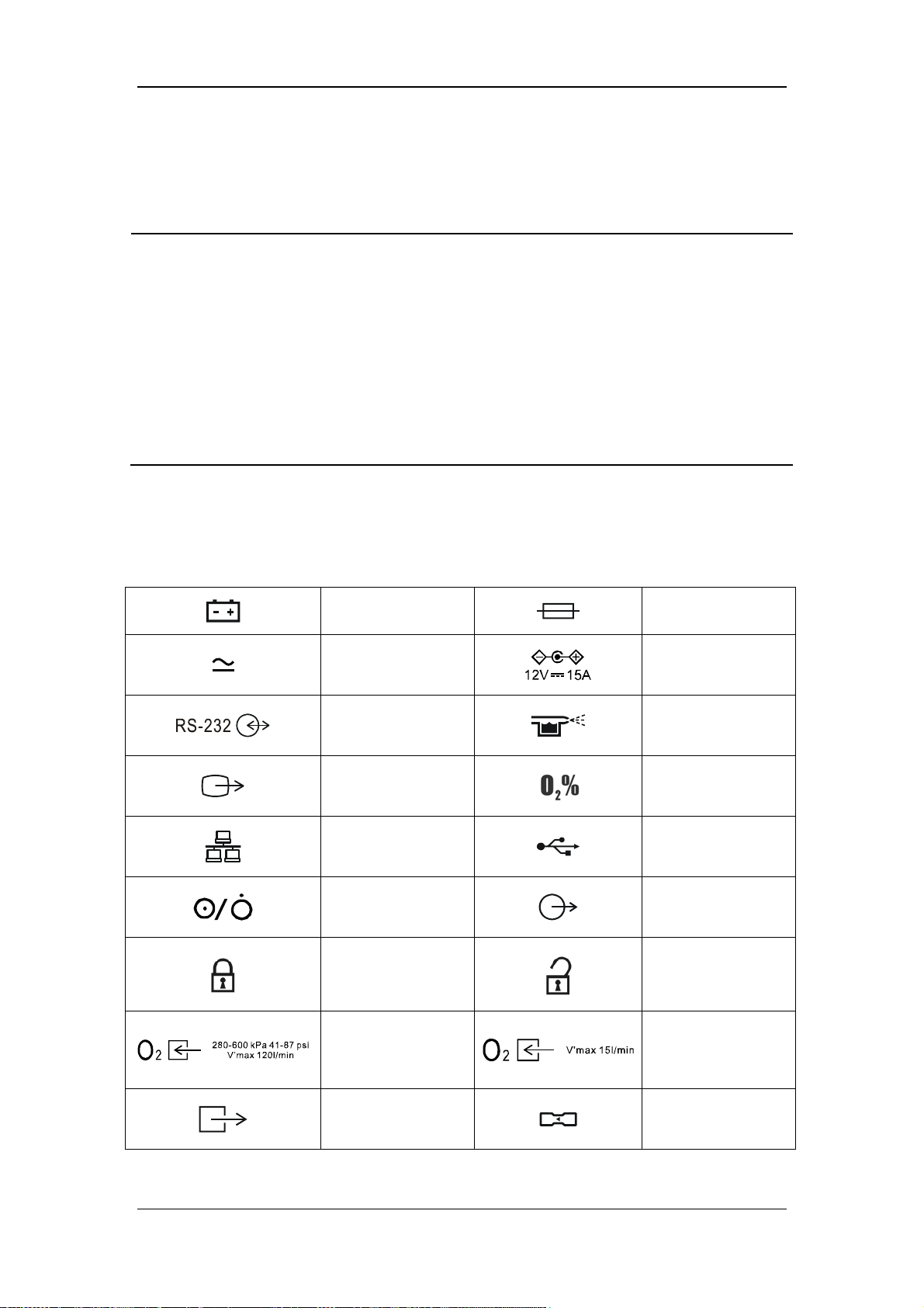
1.2 Equipment Symbols
Battery
AC/DC power
indicator light
RS-232 connector
VGA output
connector
Network connector
Power switch
Lock
Fuse
Direct current input
port
Nebulizer connector
Oxygen sensor
connector
USB connector
Nurse call connector
Unlock
High-pressure
oxygen supply
connector
Ventilator gas outlet
1-7
Low-pressure
oxygen supply
connector
Flow sensor
Page 18
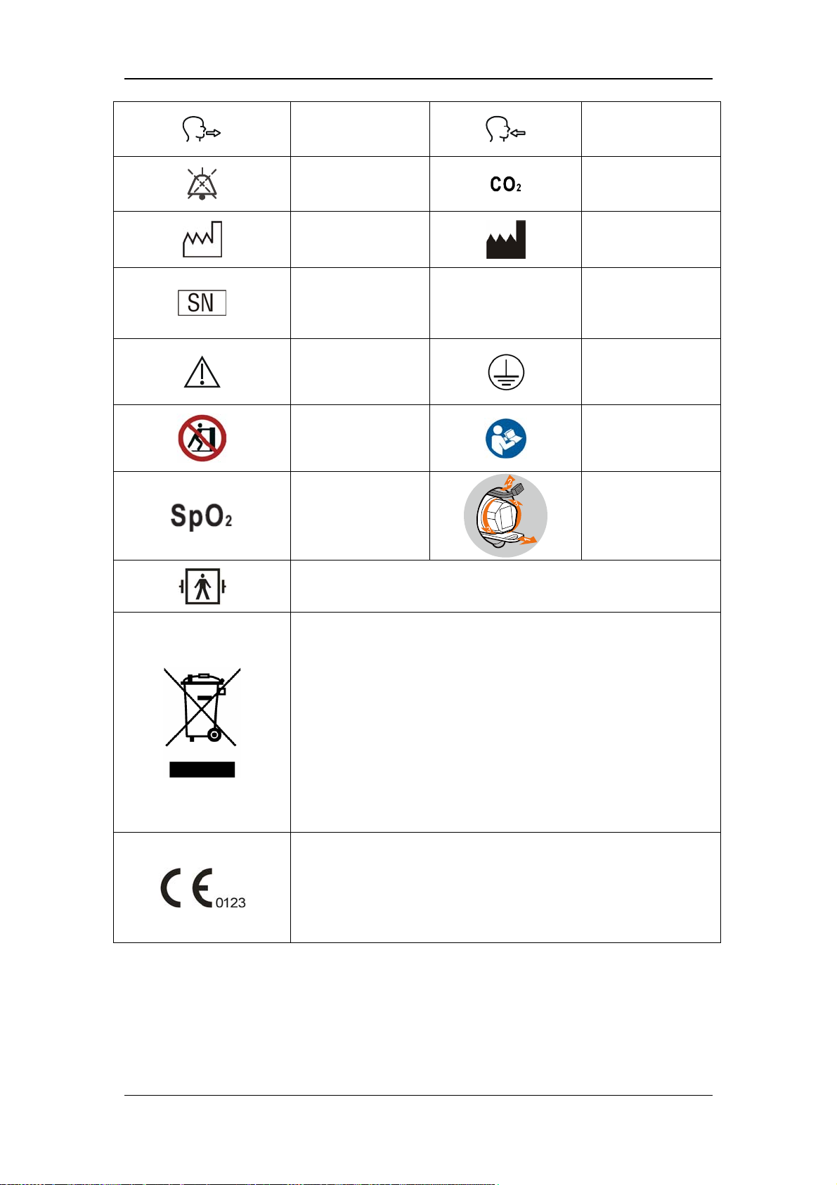
Expiration
connector
AUDIO PAUSED
Date of manufacture
Serial number IP21
Caution
no pushing
SpO2 module
Inspiration
connector
CO2 module
Manufacturer
Degree of protection
provided by
enclosure
Protective earth
ground
Refer to the
operator's manual
Disassemble the O2
sensor
Type BF applied part. Defibrillation-proof protection against electric
shock.
The following definition of the WEEE label applies to EU member
states only.
This symbol indicates that this product should not be treated as
household waste. By ensuring that this product is disposed of
correctly, you will help prevent bringing potential negative
consequences to the environment and human health. For more
detailed information with regard to returning and recycling this
product, please consult the distributor from whom you purchased it.
* For system products, this label may be attached to the main unit
only.
The product bears CE mark indicating its conformity with the
provisions of the Council Directive 93/42/EEC concerning medical
devices and fulfils the essential requirements of Annex I of this
directive.
Note:The product complies with the Council Directive 2011/65/EU.
1-8
Page 19
2 Theory of Operation
2.1 Pneumatic Circuit
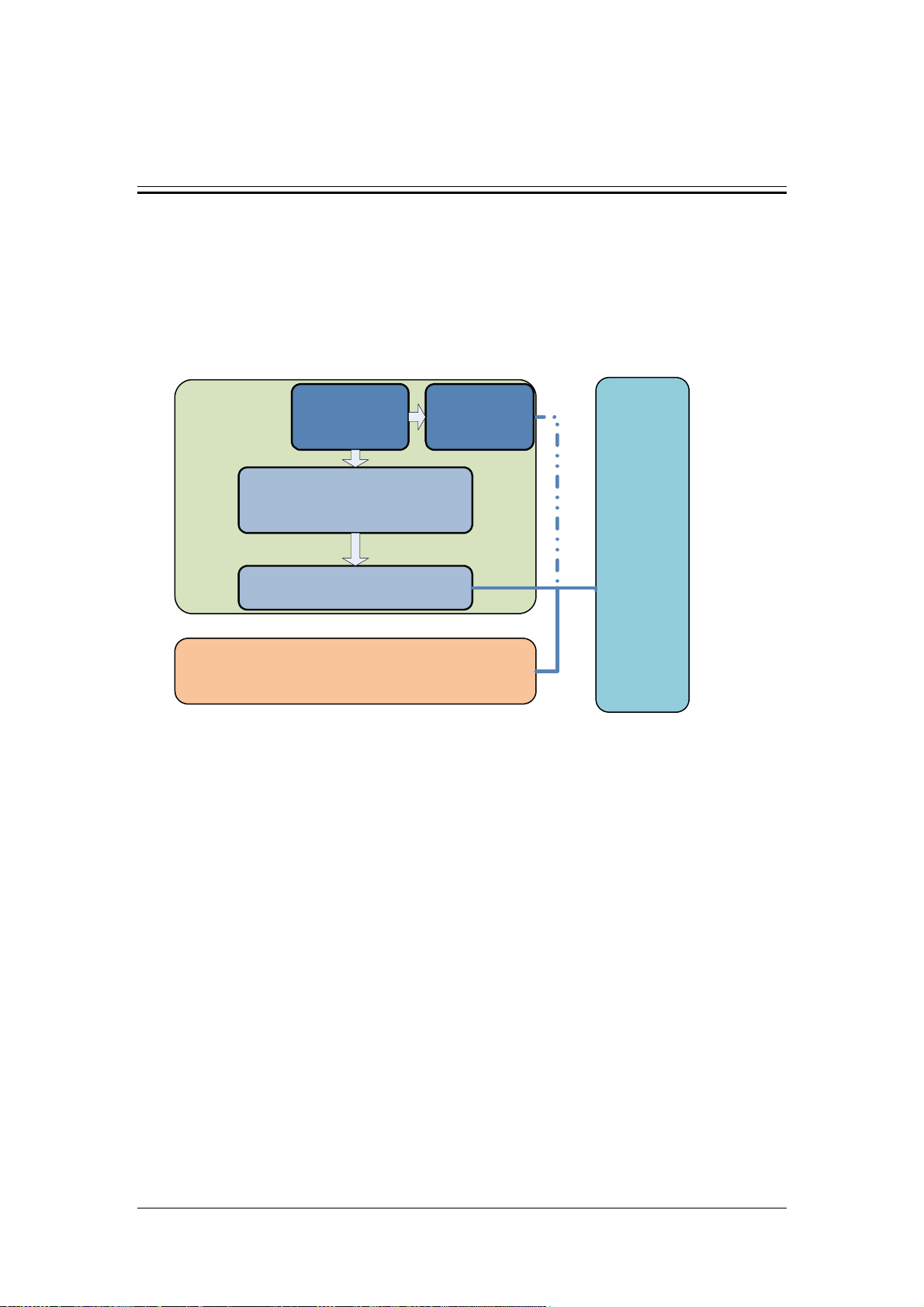
2.1.1 Overview of the Pneumatic System
The pneumatic system consists of three parts: inspiratory limb, patient tube, and expiratory
limb. The inspiratory limb can be further divided into gas supply and nebulizing subsystem,
blower and flow control subsystem, and safety valve subsystem.
Nebulizing
subsytem
Insp.
limb
Gas supply
subsystem
Blower and flow control
subsystem
Patient
tube
Safety valve subsystem
Exp. limb
As shown above, the patient tube plays the role of bridge between the inspiratory limb and
the expiratory limb. The gas supply and nebulizing subsystem is connected with the patient
tube as required to implement the nebulizing function. These subsystems form a closed
circuit for the ventilator to implement the ventilation management function.
2-1
Page 20
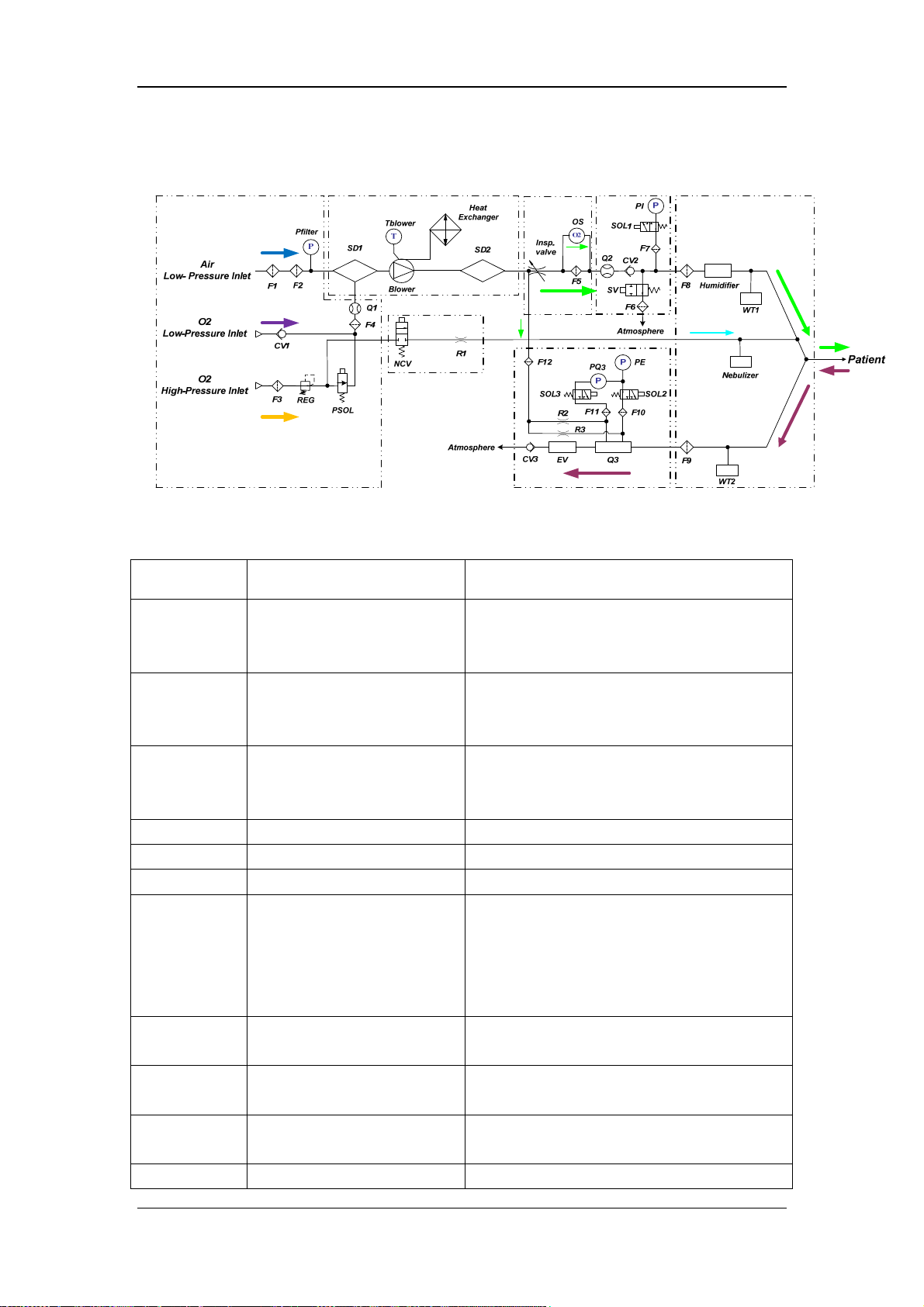
2.1.2 Pneumatic Circuit Diagram
2.1.2.1 Parts List
Symbol Name Function and Index
Air
Low-Pressure
Inlet
O2
Low-Pressure
Inlet
O2
High-Pressure
Inlet
F1 Dust filter Filters dust in the Air supply
F2 HEPA filter Filters bacteria and viruses in the Air supply
Pfilter Pressure sensor Monitors vacuum at the Air inlet
CV1 Self-closing cut-off valve
F3 Filter
REG Regulator
PSOL Proportional solenoid valve
Q1 O2 flow sensor Monitors O2 flow
Low-pressure Air inlet Air inlet
Low-pressure O2 inlet
High-pressure O2 inlet
O2 connector, quick connector, compatible
with (CPC) PMC series
O2 connector, NIST/DISS optional, supply gas
pressure is 2.8-6bar
Cuts off the connection between the
low-pressure O2 limb of the pneumatic system
and the outside environment when the
ventilator does not connect with the
low-pressure O2.
Filters foreign substance in the high-pressure
O2 supply
Reduces and stabilizes the pressure of
high-pressure O2 supply to 2.0±0.1bar
High-pressure O2 proportional valve, output
peak flow≥120 L/min@6bar
2-2
Page 21

Symbol Name Function and Index
F4 Filter screen Stabilizes gas flow
SD1
Blower Turbo blower
Tblower Temperature sensor Monitors the blower temperature
SD2
Heat
Exchanger
Inspiratory
valve
Q2 Flow sensor of the mixed gas Monitors the flow of mixed gas
OS O2 sensor Monitors O2 concentration
F5 Filter screen Stabilizes gas flow
CV2 Check valve
SV Safety valve
F7 Filter for pressure sensor Protects the pressure sensor
SOL1
PI Inspiratory pressure sensor Monitors the pressure in the inspiratory limb
F8 Inspiratory filter
Humidifier Humidifier Heats and humidifies the patient’s inspired gas
WT1/WT2 Water trap Collects condensed water inside the tube
NCV Nebulizer control valve Controls the on-off of the nebulizer limb
R1 Nebulizer needle valve Restricts the output flow of the nebulizer limb
Nebulizer Nebulizer
F9 Expiratory filter
Noise reduction and Air&O2
mixed chamber
Noise reduction and Air&O2
mixed chamber
Heat exchanger Heat dissipating device of the blower
Inspiratory valve Controls the flow in the inspiratory limb
Inspiratory pressure zeroing
three-way valve
Air&O2 mixed channel, reduces the front-end
noise of the blower subsystem
Mixes the Air and O2 and improves the
pressure of mixed gas to the preset value
Further mixes the Air and O2 and reduces the
rear-end noise of the blower subsystem
Prevents gas from flowing in the reverse
direction
Pressure relief and spontaneous inspiratory
channel
Performs switchover between inspiratory
pressure measurement and zeroing
Prevents water vapor and bacteria inside the
patient tube from entering the ventilator
internal pneumatic circuit
Device which turns nebulized liquid medicine
into gaseous colloidal particles
Prevents water vapor and bacteria inside the
patient tube from entering the expiratory
module
Q3 Expiratory flow sensor Monitors expiratory gas flow
F10/F11 Filter Protects pressure zeroing three-way valve
F12 Filter
SOL2
Pressure zeroing three-way
valve
Protects upstream limb from being polluted by
the exhaled gas
Expiratory pressure sensor zeroing and
pressure zeroing in the upstream of expiratory
2-3
Page 22
r
Symbol Name Function and Index
flow sensor diaphragm
SOL3
Pressure zeroing three-way
valve
Pressure zeroing in the downstream of
expiratory flow sensor diaphragm
PQ3 Differential pressure sensor Expiratory differential pressure sensor
PE Expiratory pressure sensor Expiratory pressure sensor
R2/R3 Flushing resistor Restricts flushing flow
EV Expiratory valve
Controls system PEEP or Plimit via voice coil
motor
CV3 Check valve Ensures unidirectional gas flow
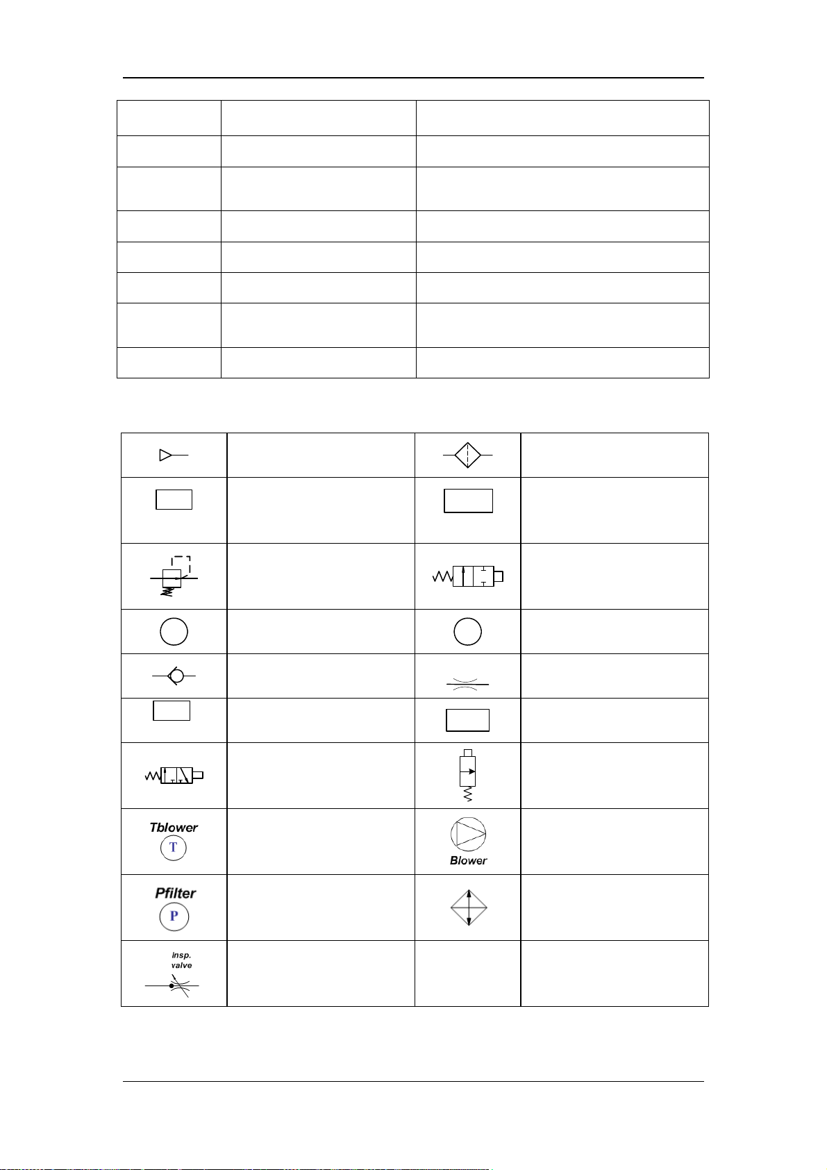
2.1.2.2 Symbols
Filter
Humidifier
WT
Gas supply
Water trap
Humidifie
Regulator
On-off valve (two-position
two-way solenoid valve)
O2
Nebulizer
O2 sensor
Check valve
Nebulizer
Two-position three-way
solenoid valve
P
R
Q
Pressure sensor
Resistor
Flow sensor
Proportional solenoid valve
Temperature sensor
Vacuum sensor at the Air
inlet
Turbo blower
Turbine heat exchanger
Inspiratory valve / /
2-4
Page 23
2.1.3 Theory of Operation of the Pneumatic Subsystem
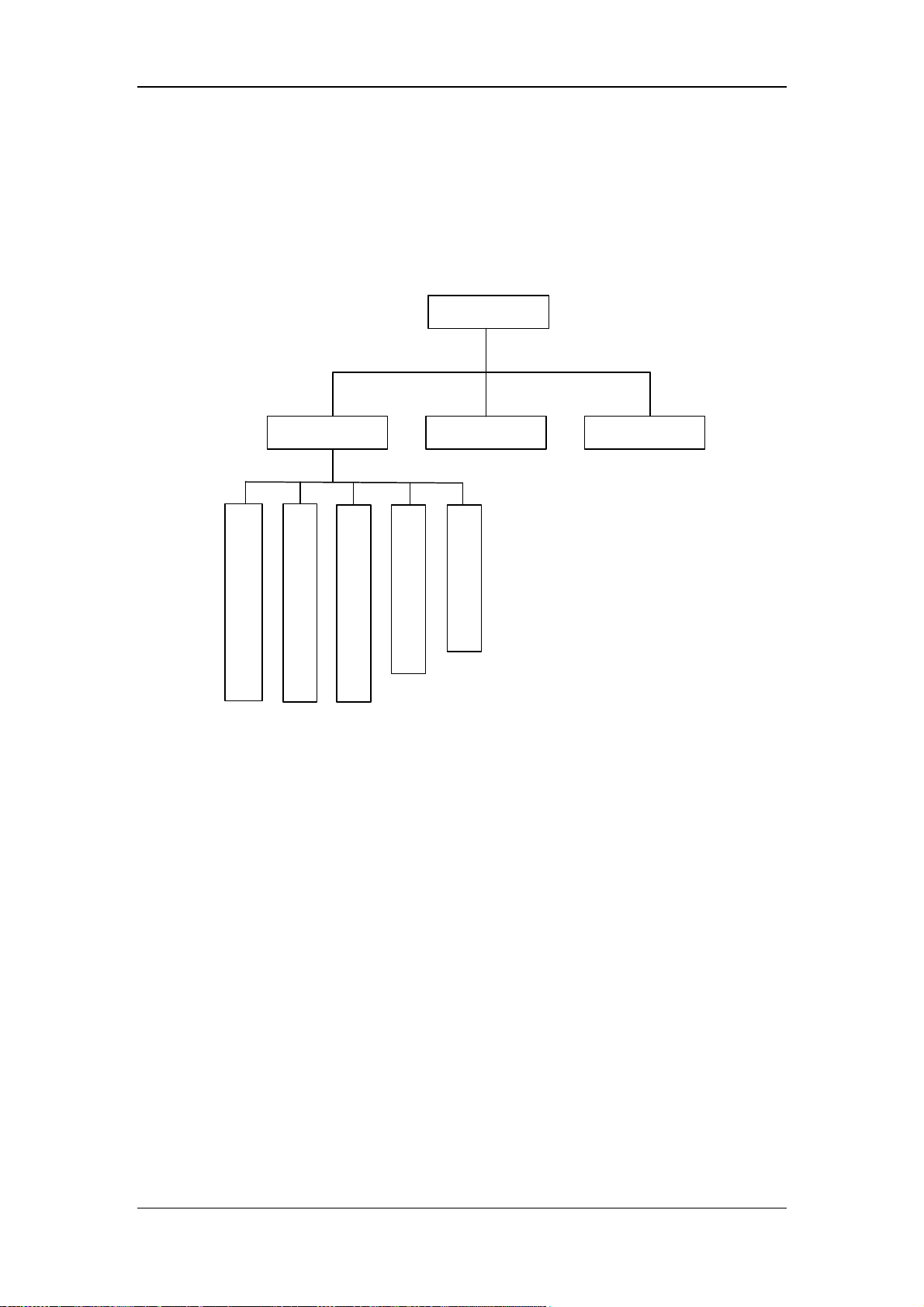
According to structural composition and function, the pneumatic system of the ventilator can
be broken down into 7 parts as shown below, which are gas supply subsystem, turbo blower
subsystem, flow control subsystem, safety valve subsystem, nebulizing subsystem, patient
tube and expiratory assembly.
Pneumatic system
Exp. assembly
Gas supply subsystem
Insp. assembly
Turbo blower subsystem
Flow control subsystem
Patient tube
Safety valve subsystem
Nebulizing subsystem
2.1.3.1 Gas Supply Subsystem
The schematic diagram of the gas supply subsystem is as shown below. The gas supply
subsystem includes three limbs: high-pressure O2, low-pressure O2, and low-pressure Air.
The room air enters the machine after passing through dust filter F1 and HEPA filer F2. O2
enters the machine after passing through high-pressure O2 limb or low-pressure O2 limb.
Flow sensor Q1 is placed at the outlet where low-pressure O2 and high-pressure O2 converge
to monitor O2 flow entering the machine.
2-5
Page 24
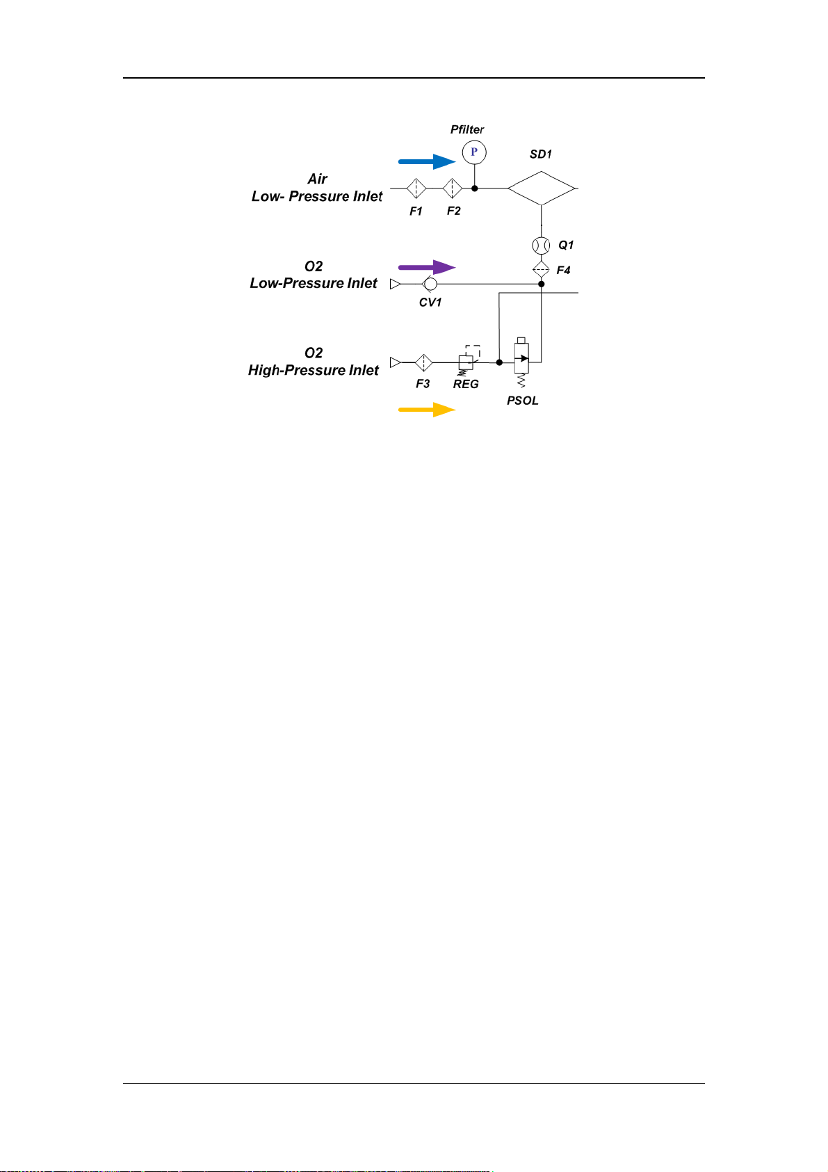
The gas supply subsystem is the starting part of the ventilator’s pneumatic circuit. It
introduces external O2 and room air into the machine. A dust filter is necessary at the Air
inlet as there is dust and foreign substance inside the room air. Meanwhile, to filter the
bacteria and viruses inside the room air, HEPA filter is placed at the Air inlet to ensure the air
entering the machine is clean and aseptic. After the machine is used or placed for a period of
time, dust or foreign substance may be absorbed on the surfaces of the dust filter at the Air
inlet and HEPA filter. When the dust or foreign substance is accumulated to a certain extent,
occlusion occurs at the Air inlet, which may cause insufficient air intake of the machine. By
placing vacuum sensor Pfilter at the Air inlet, occlusion at the Air inlet can be effectively
monitored. If the Air inlet is occluded and the Air supply pressure is too low, vacuum sensor
Pfilter gives an alarm reminding the user to replace the HEPA filter.
2-6
Page 25
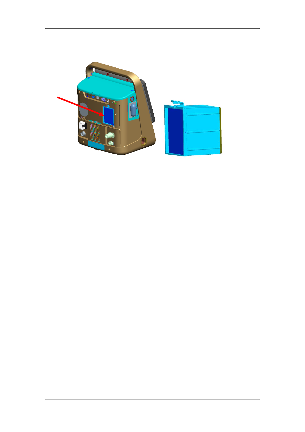
The following picture shows the position of Air inlet and HEPA filter.
The connector of high-pressure O2 inlet is designed to be NIST/DISS as required by the
standard to prevent misconnection. The connector of low-pressure O2 inlet is designed to be
quick connector which is compatible with (CPC) PMC series and provides pneumatic cut-off
function to prevent gas error between the high-pressure O2 and low-pressure O2 inside the
ventilator. Air passes through the dust filter and HEPA filter to enter the machine. There is no
standard requirement for the type of Air connector and it is designed to be non-standard
connector. The regulator in the high-pressure O2 limb reduces the supply gas pressure and
stabilizes it at 2.0±0.1bar to ensure stable output and good repeatability of solenoid
proportional valve PSOL at the rear end.
2-7
Page 26
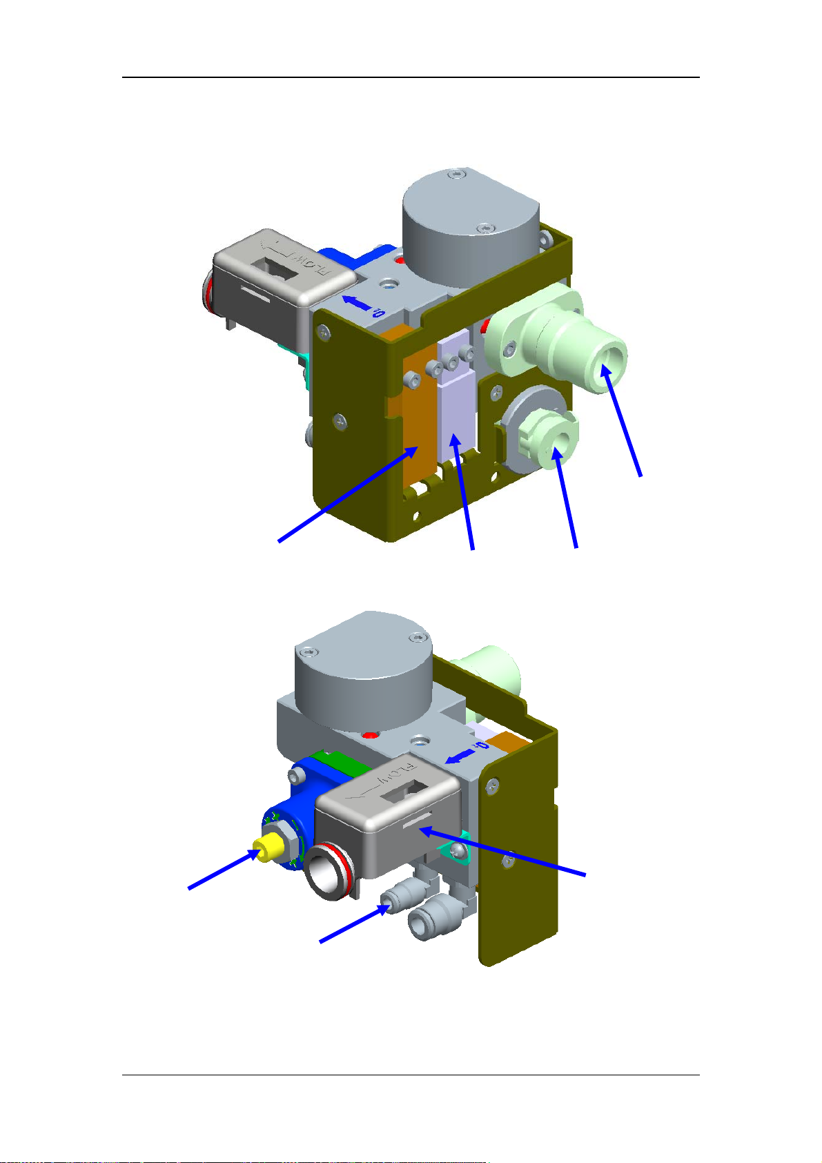
The O2 inlet assembly is as shown below.
O2 proportional valve
Nebulizer switch valve
High-pressure O2
connector compatible
with NIST/DISS
Low-pressure O2 CPC
quick connector
Regulator
O2 flow sensor
Nebulizer outlet
2-8
Page 27
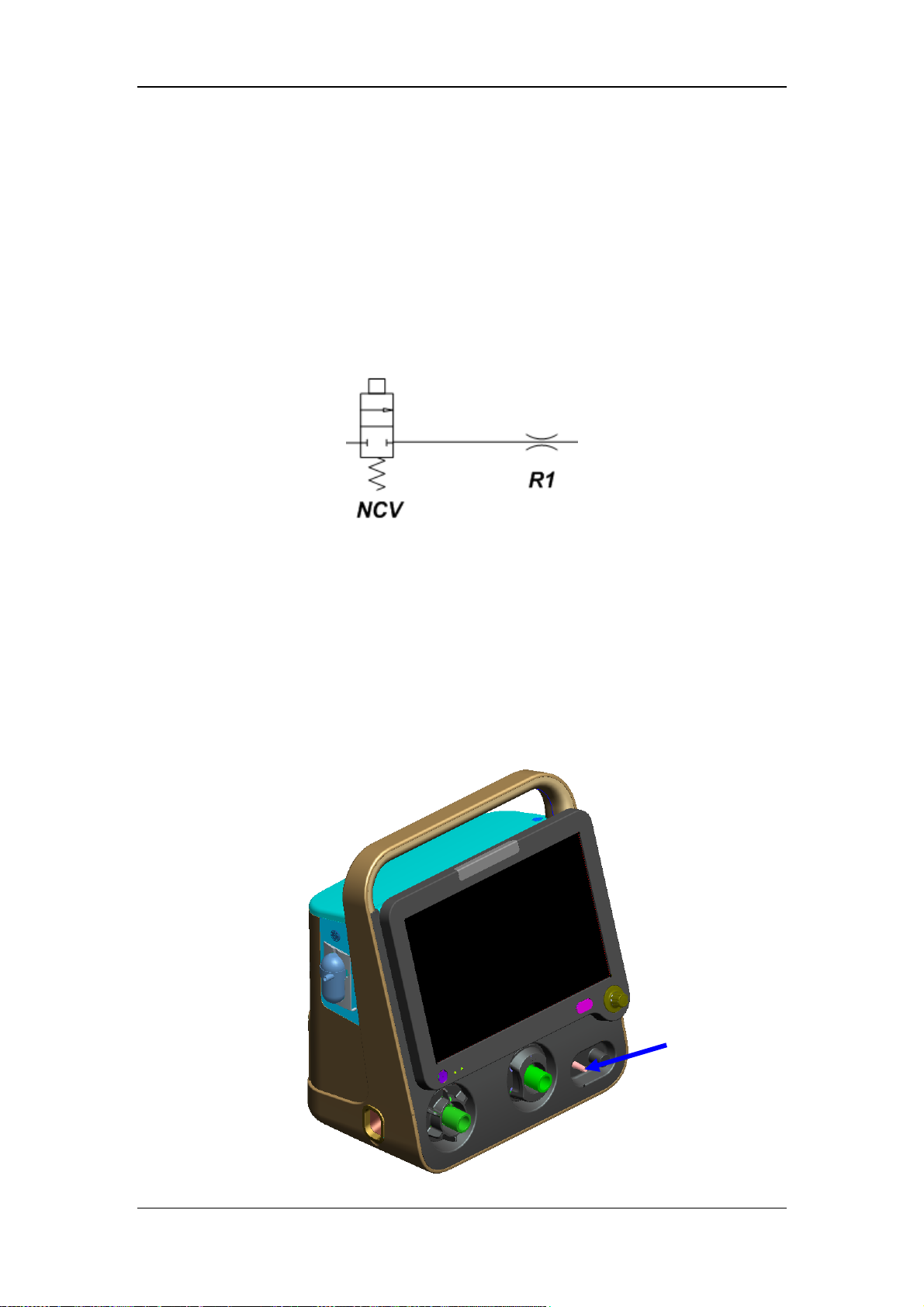
2.1.3.2 Nebulizing Subsystem
The nebulizing control subsystem controls the on-off of nebulized gas flow via NCV, so as to
realize control of nebulizer by nebulized gas flow (nebulizer needs to be configured
separately and is independent of the ventilator main unit). When applying the nebulizer
function, note that the nebulizing subsystem is enabled only when the system is connected
with high-pressure O2 supply. Check if the machine is already connected with high-pressure
O2 supply before using this function.
The diagram of the nebulizing control subsystem is as shown below.
NCV is a solenoid two-way valve and it has two states: ON and OFF. R1 is a nebulizer
needle valve. It adjusts nebulized gas flow by adjusting the position of the needle valve.
When NCV is connected, O2 of 2.0-6.0bar is at its front end. By adjusting the position of the
needle valve in advance, there is continuous flow of 6-9 L/min at its rear end. Such flow
flows into the nebulizer via the nebulizing nozzle, takes away medicine and finally flows into
the patient. The external structure and size of the nebulizing nozzle comply with BS EN
13544-2_2002 standard.
2-9
Nebulizing nozzle
Page 28
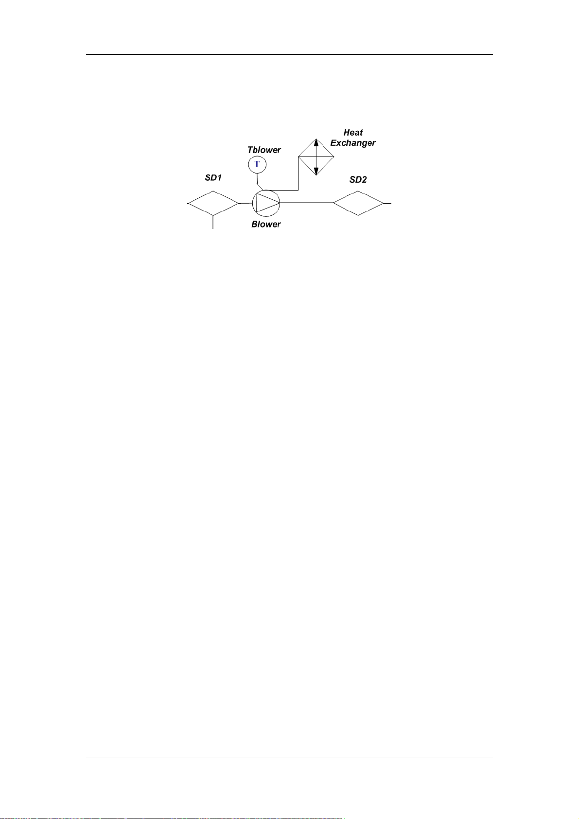
2.1.3.3 Turbo Blower Subsystem
The schematic diagram of the turbo blower subsystem is as shown below.
The turbo blower subsystem mixes Air and O2 and delivers the mixed gas to the lower level
assembly. The turbo blower subsystem is composed of blower, heat exchanger, oxygen
mixture outlet box assembly, HEPA filter, negative pressure sensor, labyrinth chamber
assembly, additional temperature sensor, shock-absorbent material, and silencing sponge.
The heat exchanger connects with the blower to conduct the heat produced by the blower
outside. Meanwhile, the mixed gas which flows through the blower carries away some heat
produced by the turbo blower subsystem. The temperature of the blower affects the service
life directly. Therefore, the working temperature of the blower is monitored by the additional
temperature sensor (Tblower). If the temperature exceeds the standard, the cooling fan is
speeded up to increase the heat-sinking capability of the blower.
Negative pressure sensor is used for monitoring the actual negative pressure at the inlet of the
turbine. If the negative pressure exceeds 8kPa, the alarm message [Replace HEPA filter] is
displayed on the screen. And then the HEPA filter must be replaced.
2-10
Page 29
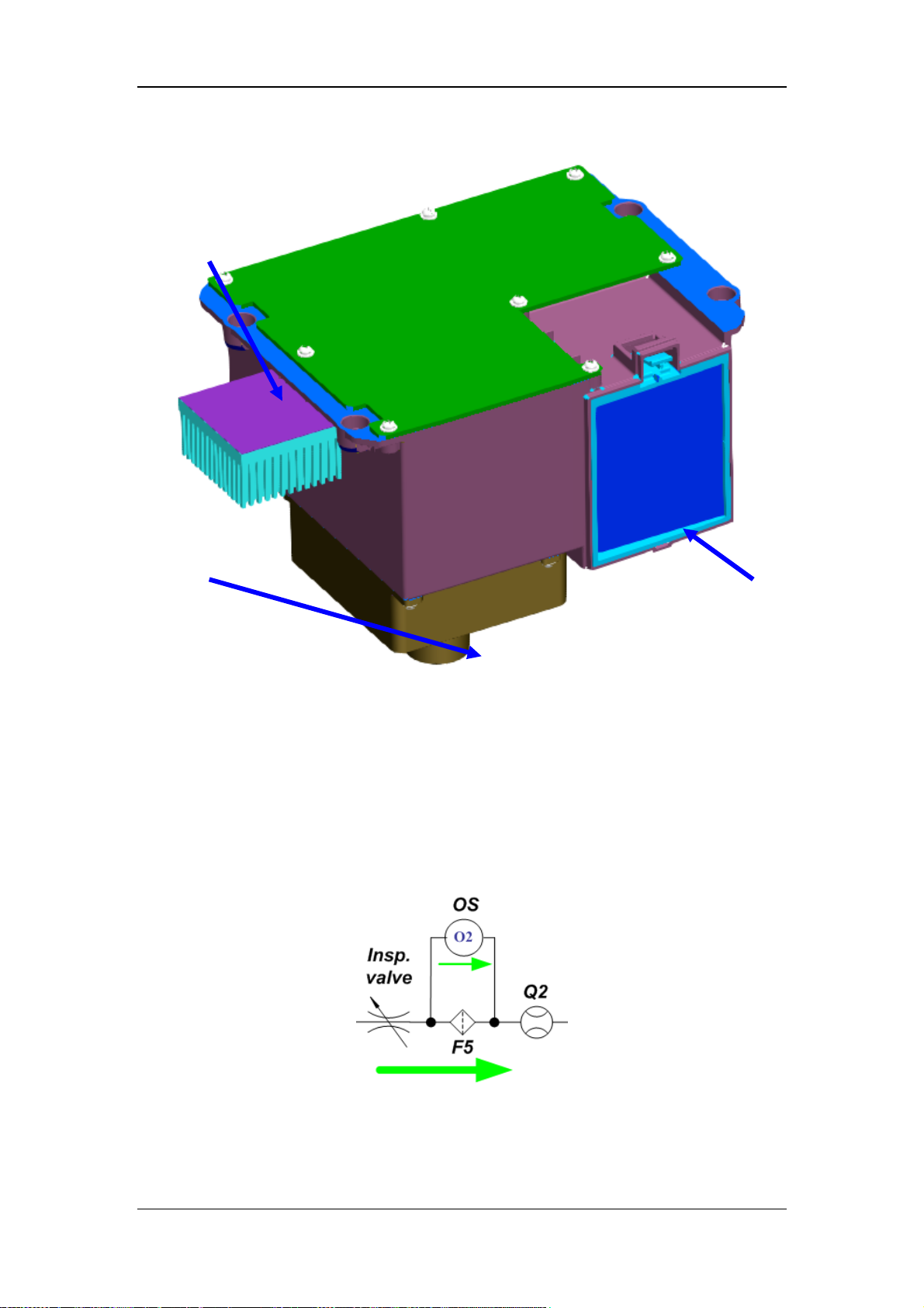
The structural components of the turbo blower subsystem are as shown below.
Turbine heat
exchanger
Mixed O2 outlet box
HEPA filter
2.1.3.4 Flow Control Subsystem
The chief component of the flow control subsystem is low-pressure large-diameter
inspiratory valve. It controls the opening and closing of the valve port via voice coil motor
and provides the required pressure and flow for the system. The large-diameter inspiratory
valve assembly also provides gas supply for monitoring O2 concentration. The schematic
diagram of the flow control subsystem is as shown below.
2-11
Page 30
The component structure of the flow control subsystem is as shown below.
Inspiratory valve shell
Voice coil motor
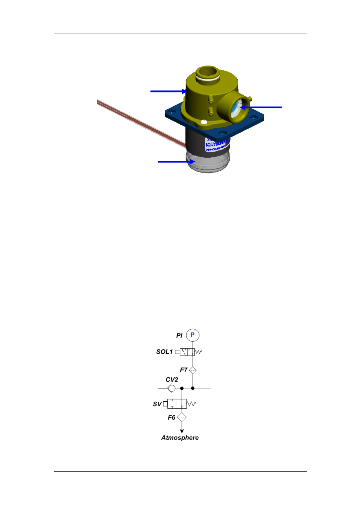
2.1.3.5 Safety Valve Subsystem
The safety valve module is located in the downstream of the inspiratory flow sensor. As the
inspiratory channel of the system, it is connected with the external breathing tubes or other
medical accessories. This module has two functions. One is active pressure relief to prevent
the pressure of the pneumatic system from exceeding the preset pressure. The relief pressure
can be preset as required by the operator. The relief mechanism is controlled by software. The
other is to provide channel for patient’s spontaneous breathing when the system is powered
off or standby, to prevent patient apnea.
The safety valve module closes or opens the safety valve by controlling the power-on/-off of
the electromagnet.
The schematic diagram of the safety valve subsystem is as shown below.
Encapsulated
filter screen
2-12
Page 31
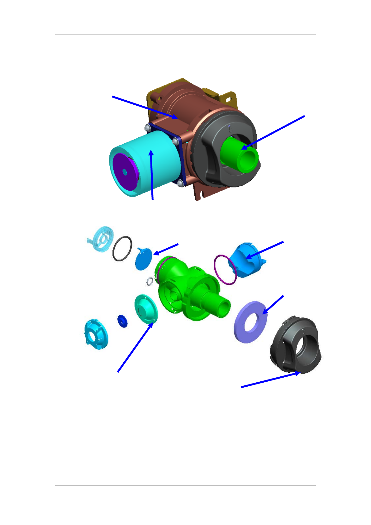
The corresponding component structure is as shown below.
Safety valve
base assembly
Detachable part of
the safety valve
Electromagnet
Check valve
diaphragm
Safety valve diaphragm
The module has fixed part and detachable part. The fixed part includes electromagnet, safety
valve base, and floating mechanism. This part is fixed to the machine bracket via screws to
support the overall safety valve assembly. The detachable part includes safety valve
diaphragm, safety valve main body, check valve diaphragm, safety valve plug, and safety
valve knob. This part provides controlled breath and spontaneous breathing channel for the
patient. It can be detached without tools by the client for cleaning and disinfection.
The external output port of the safety valve subsystem is the outlet part of the gas reservoir.
This port complies with coaxial 22mm conical connector specified by ISO 5356-2:1987.
Safety valve knob
Safety valve plug
Safety valve
dust-proof pad
2-13
Page 32
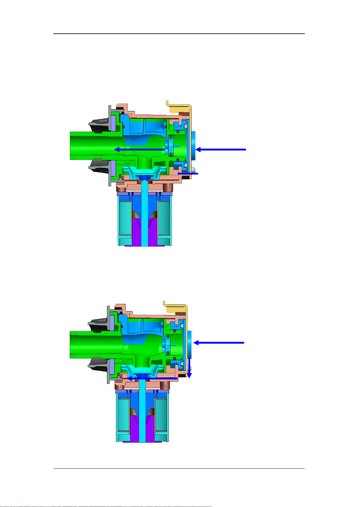
The gas flow of the safety valve includes the following cases:
1. When the ventilator ventilates normally, the electromagnet is powered on and seals the
valve port. O2 enter the patient via safety valve channel. The gas flow is as shown
below.
2. When the airway pressure is too high, the electromagnet is powered off and opens the
pressure relief channel actively to ensure patient safety. The gas flow is as shown below.
When the airway pressure returns to normal, the electromagnet is powered on. Gas
flow returns to that described in case 1.
2-14
Page 33
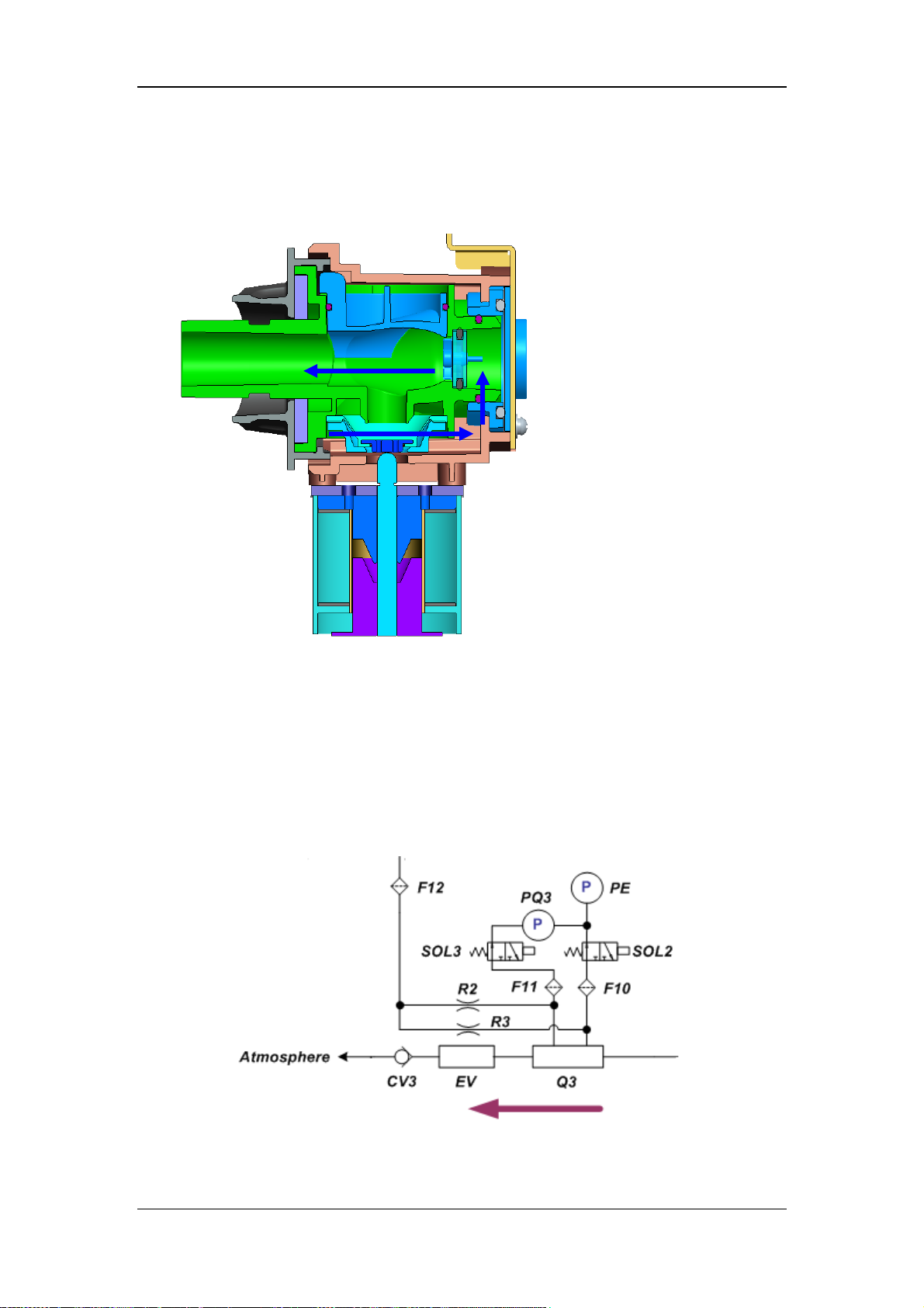
3. When the machine is powered off inadvertently, the electromagnet is powered off and
opens the pressure relief channel. The patient obtains air from the atmosphere. The gas
flow is as shown below.
2.1.3.6 Expiration Assembly
The expiration module implements pressure control, pressure monitoring, and flow
monitoring during the patient expiratory phase. It differs from the inspiration module in that
the gas that passes through it is the patient’s exhaled gas. This results in the need to clean and
disinfect the components of the expiration module before reuse. The diagram is as shown
below.
The expiratory valve (EV) is an electronically controlled valve. The expiratory valve closing
2-15
Page 34

pressure is controlled by the voice coil motor. When the control current the system gives to
the voice coil motor is zero, the expiratory valve fully opens. When the system gives the
voice coil motor certain control current, the voice coil motor seals the diaphragm to the valve
port with certain pushing force. The patient’s exhaled gas must overcome the valve port
sealing force of the gas inside the expiratory valve cavity in order to pass the valve port. This
dynamic process finally guarantees that the airway pressure is a setting value (this value
corresponds to the control current of the voice coil motor).
During the inspiratory phase, the system gives the voice coil motor relatively large control
current to seal the valve. The corresponding valve closing pressure differs with the
parameters set under vent mode (Plimit in V-A/C mode, Pinsp+PEEP in P-A/C mode,
Psupp+PEEP in PSV mode). Gas enters the patient first. If the airway pressure is greater than
the valve closing pressure during the inspiratory phase, the expiratory valve diaphragm opens
to relieve pressure to ensure patient safety.
During the expiratory phase, the system gives the voice coil motor zero or relatively small
control current, which corresponds to expiratory valve fully open or forming certain valve
closing pressure. When the expiratory valve fully opens, it is equivalent to the case that the
patient’s exhaled gas is directly vented to the atmosphere (same to expiration by a normal
person). If the expiratory valve has certain valve closing pressure, it is equivalent to the case
that the patient’s exhaled gas is always kept above positive pressure; namely, the patient’s
expiratory pressure is the set PEEP value.
The expiratory flow sensor (Q3) is based on the principle of differential pressure. A
diaphragm-type sensor (metallic diaphragm flow sensor) is use, which is characterized by
high sensitivity. The expiration module uses metallic diaphragm flow sensor to support 134℃
autoclaving. The diaphragm will get distorted after long term of use. Therefore, it needs to be
calibrated periodically to maintain measurement accuracy.
When the gas flows through Q3, a pressure difference is produced on both sides of the Q3
diaphragm. Flow information is acquired through processing this pressure difference after it
is collected by differential pressure sensor PQ3. SOL2 and SOL3 are corresponding zeroing
three-way valve. Pressure sensor PE is the sensor measuring the pressure in the expiratory
limb. It uses front-end sampling line of Q3 to collect pressure signals.
In addition, there are two limbs passing through R2 and R3. They produce small flushing gas
flow in the pressure sampling line to prevent water vapor from condensing in the pressure
sampling line and affecting the accuracy of pressure measurement.
2-16
Page 35
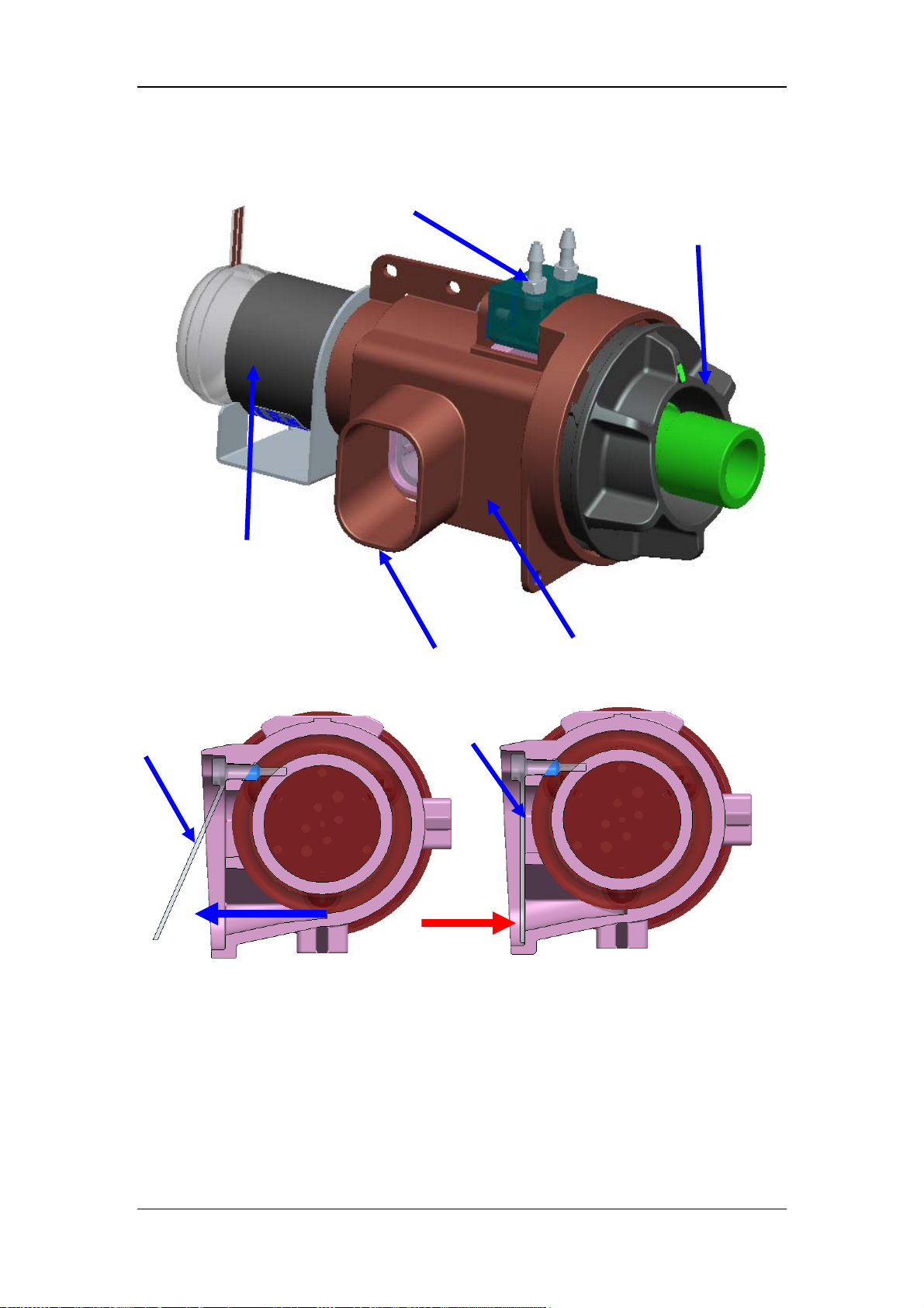
p
The component structure of expiration module is as shown below.
Voice coil motor
Sampling seat assembly
Patient gas outlet
Disinfectable expiratory
iratory valve seat
Ex
valve assembly
Expiratory check
valve open
2.1.3.7 Patient Tube
Patient tube is the peripheral pneumatic circuit of the ventilator, independent of the
ventilation main unit. It can be configured as needed. Patient tube connects the ventilator
with the patient and humidifies the patient’s inhaled gas. Its diagram is as shown below.
Expiratory check
valve closed
2-17
Page 36
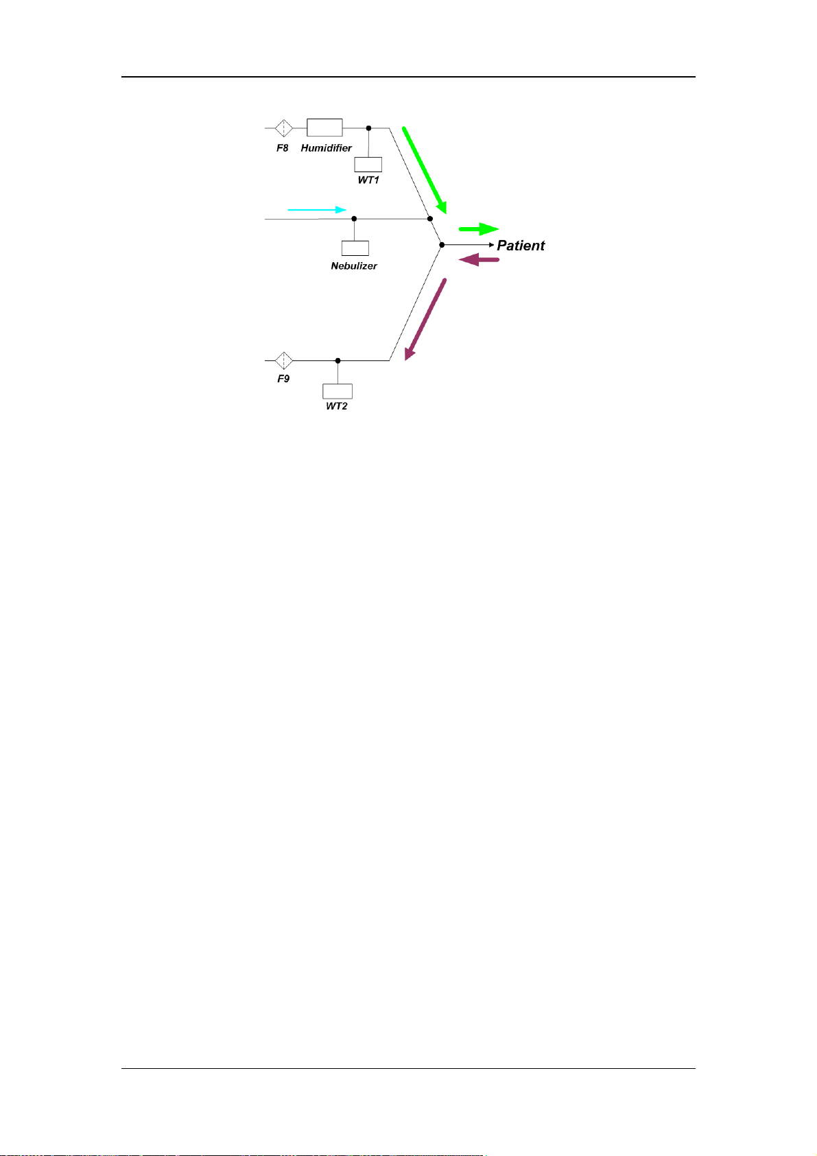
There are disposable and reusable patient tubes. Generally, disposable tubes integrate tube,
water trap, and Y piece, and are made of PVC material. They are of low cost and are
discarded after use. Reusable tubes, typically, are made of silicone which can be autoclaved
for many times. The water trap and Y piece can also be autoclaved. Despite the high cost,
reusable tubes reduce clinical cost since they can be used for many times.
Filters are placed at the inspiration port and expiration port of the ventilator. The filtering
accuracy is 5um. The filters can effectively prevent bacteria inside the patient tube from
entering the ventilator’s pneumatic circuit.
The humidifier is placed in the inspiratory tube. After passing through the humidifier, the
mixed dry gas the ventilator outputs become warm saturated gas and then enter the patient’s
respiratory tract, avoiding bring discomfort and complication to the patient.
The nebulizer is connected with the nebulizing nozzle on the front panel of the machine. It
turns nebulized liquid medicine into gaseous colloidal particles. During the patient’s
inspiration, the medicine is delivered to the patient’s respiratory tract and lungs together with
the nebulized gas to treat the patient.
2-18
Page 37
2.2 Electrical Circuit
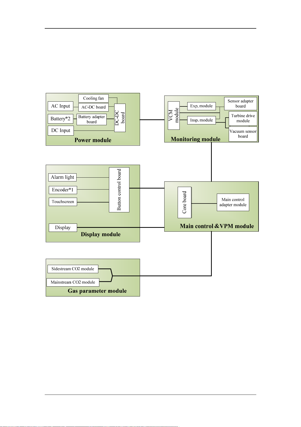
2.2.1 Overview of the Hardware Boards
The block diagram of SV300/350 hardware system is as shown below. The connection lines
in the diagram indicate the connection between hardware boards and that between modules.
2-19
Page 38

The SV300/350 hardware system is divided into the following modules: power module, main
control&VPM module, monitoring module, display module, gas parameter module etc.
1. Power module: includes AC input, cooling fan, AC-DC board, battery, DC-DC board,
battery adapter board; provides power supply for the whole ventilator system.
2. Main control&VPM module: includes main control core board, peripheral drive
interface etc; fulfills man-machine interaction of the ventilator, data interaction with
other modules and subsystems; extends USB and network interfaces.
3. Monitoring module: includes VCM module, inspiration module, expiration module,
vacuum sensor board, sensor adapter board etc.; fulfills pressure and flow monitoring,
valve control, O2 concentration collection, data interaction with the main control board.
4. Display module: includes LCD screen, touchscreen, alarm light board, encoder board,
button control etc.
5. Gas parameter module: includes sidestream CO2 module and mainstream CO2 module;
choose one from them.
2-20
Page 39
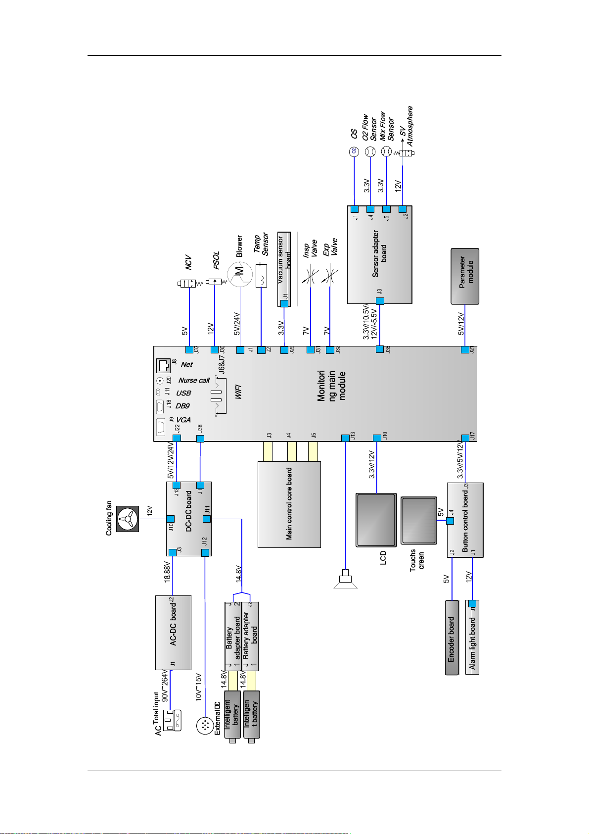
2.2.2 Electrical Circuit Diagram
2-21
Page 40
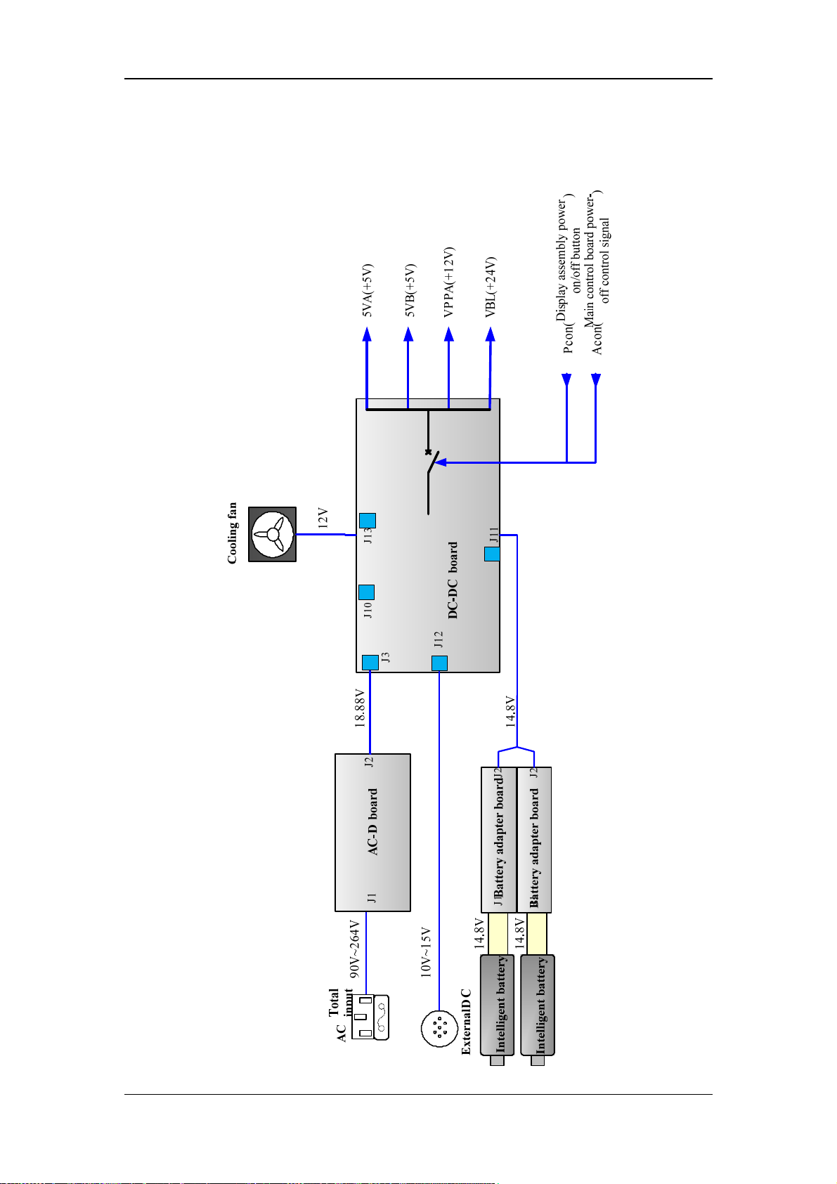
2.2.3 Power Supply System
2.2.3.1 Output of the Power Supply System
2-22
Page 41

Pcon: system power-on/off button signal for SV300/350 ventilator.
Acon: power-off signal provided by the main control board; high level for not allowing to
power off and low level for allowing to power off.
2.2.3.2 Distribution of Power Supplies in the System
Power supplies for hardware boards and their parts
Monitoring module main board +5V;+12V;+24V
Main control core board +5V
Button control board +3.3V;+5V;+12V
Alarm light board +5V
Encoder board +5V
Sensor adapter board -5V;+3.3V;+5V;+10.5V;+12V
Touchscreen +5V
Display +3.3V;+12V
Cooling fan +12V
O2 proportional valve +12V
Inspiratory/expiratory voice coil motor +7V
Nebulizing valve +5V
Turbo blower +5V;+24V
Mainstream CO2 module +5V
Sidestream CO2 module +12V
2-23
Page 42
2.2.4 Board Function
For board connections, refer to 2.2.2Electrical Circuit Diagram.
2.2.4.1 Boards of the Power Module
The power module includes AC-DC board, DC-DC board, and battery adapter board. Their
functions are:
AC-DC board : transforms the external AC input power into DC power (nominal value
is 18.88V ) to be used by the DC-DC board.
DC-DC board : Controlled by the power-on/off circuit, transforms the DC power
outputted by AC-DC, external DC input, or intelligent battery power into DC power
which the system requires to produce 5V, 12V, 24V etc, and performs charging
management of the intelligent battery.
Battery adapter board : transfer battery signals.
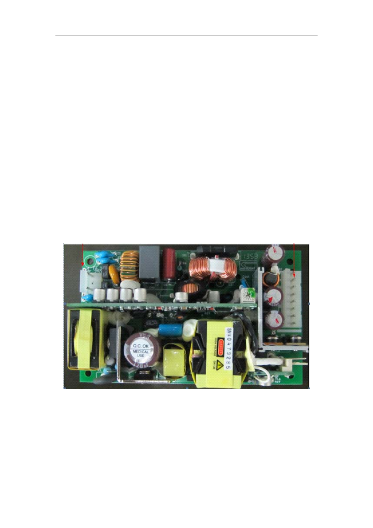
AC-DC board:
AC input AC-DC output
2-24
Page 43
AC-DC board transforms external AC into internal DC. TB1 connector is AC input connector.
It is defined as follows:
Pin No. Signal name Signal description Remark
1 L AC input 1 AC signal
2 NC No internal connection /
3 N AC input 2 AC signal
TB2 connector of AC-DC board is its DC output connector. It is defined as follows:
Pin No. Signal name Signal description Remark
1 +V Positive terminal of AC-DC output /
2 +V Positive terminal of AC-DC output /
3 +V Positive terminal of AC-DC output /
4 +V Positive terminal of AC-DC output /
5 GND Ground /
6 GND Ground /
7 GND Ground /
8 GND Ground /
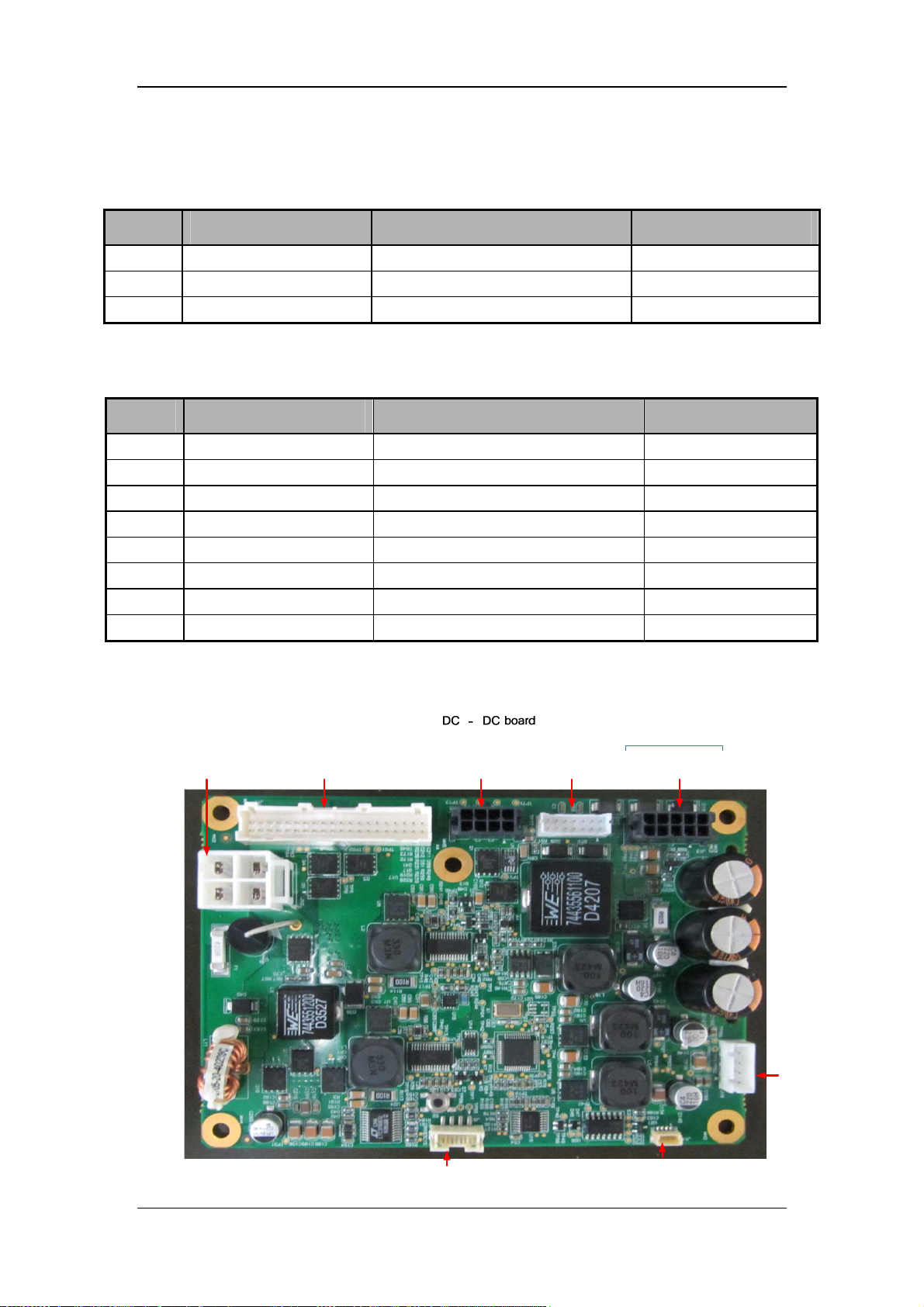
DC-DC board:
External DC
input
Battery port
AC - DC
input port
board
DC - DC
signal port
board
DC - DC
output port
power supply
Fan
2-25
Debugging portSerial port
Page 44
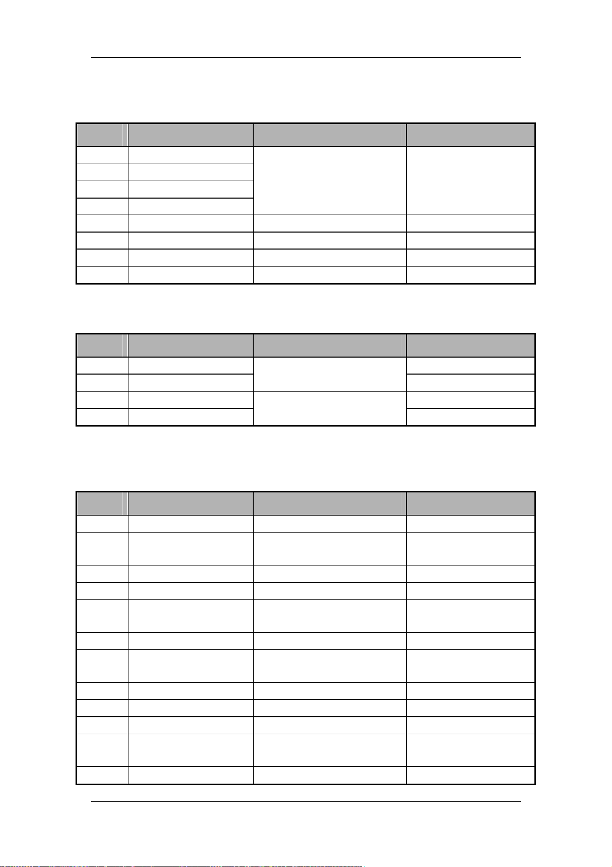
J3 connector of DC-DC board is connector with AC-DC. It is defined as follows:
Pin No. Signal name Signal description Remark
1 AC_DC_IN
2 AC_DC_IN
3 AC_DC_IN
4 AC_DC_IN
5 GND Ground /
6 GND Ground /
7 GND Ground /
8 GND Ground /
J12 connector of DC-DC board is DC input connector. It is defined as follows:
Pin No. Signal name Signal description Remark
Input signal AC-DC outputs to
DC-DC
Rated current is 8.8A
1 DC-IN+
2 DC-IN+ /
3 DC-IN-
4 DC-IN-
J11 connector of DC-DC board is the connector with battery adapter board. It is defined as
follows:
Pin No. Signal name Signal description Remark
1 GND Ground /
2 BAT1
3 GND Ground /
4 GND Ground /
5 BAT1
6 GND Ground /
7 BAT1
8 GND Ground /
9 GND Ground /
10 GND Ground /
11 BAT1
12 GND Ground /
Positive terminal of external DC
input signal
Negative terminal of external
DC input signal
Positive terminal of battery 1
input signal
Positive terminal of battery 1
input signal
Positive terminal of battery 1
input signal
Positive terminal of battery 1
input signal
/
/
/
/
/
/
/
2-26
Page 45
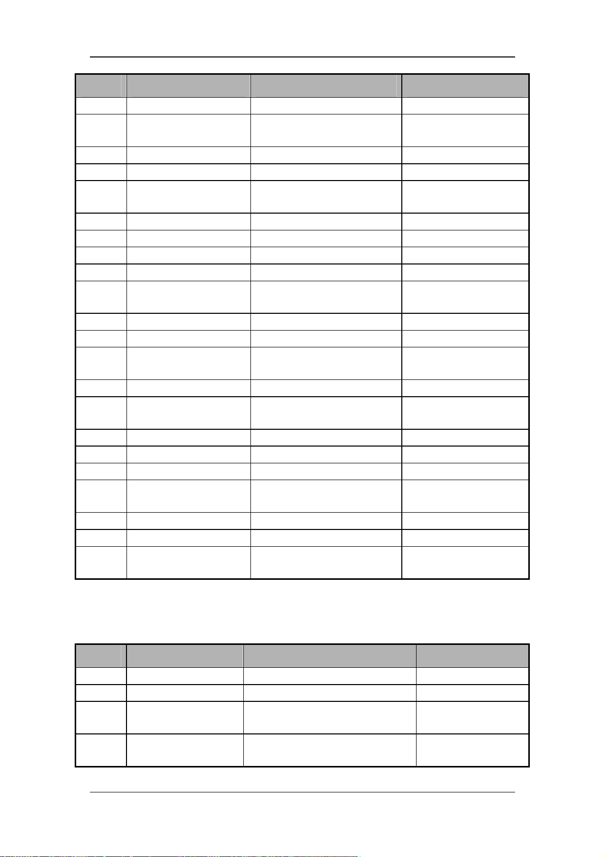
Pin No. Signal name Signal description Remark
13 GND Ground /
14 BAT1
15 BAT1_BC In-place signal of battery 1
16 SMBC1 I2C clock signal of battery 1
17 SMBC2
Positive terminal of battery 1
input signal
In-place clock signal of battery 2 /
/
/
/
18 SMBD1 I2C data signal of battery 1
19 SMBD2 I2C data signal of battery 2
20 BAT2_BC In-place signal of battery 2
21 GND Ground
22 BAT1
23 GND Ground
24 GND Ground
25 BAT1
26 GND Ground
27 BAT1
28 GND Ground
29 GND Ground
30 GND Ground
31 BAT1
32 GND Ground
33 GND Ground
34 BAT1
Positive terminal of battery 1
input signal
Positive terminal of battery 1
input signal
Positive terminal of battery 1
input signal
Positive terminal of battery 1
input signal
Positive terminal of battery 1
input signal
/
/
/
/
/
/
/
/
/
/
/
/
/
/
/
/
/
J13 connector of DC-DC board is the connector with monitoring module main board. It is
defined as follows:
Pin No. Signal name Signal description Remark
1 24VA 24V power supply of turbo blower /
2 24VA 24V power supply of turbo blower /
3 12VA
4 5VA
12V power supply of monitoring
module main board
5V power supply of VCM of
monitoring module main board
2-27
/
/
Page 46
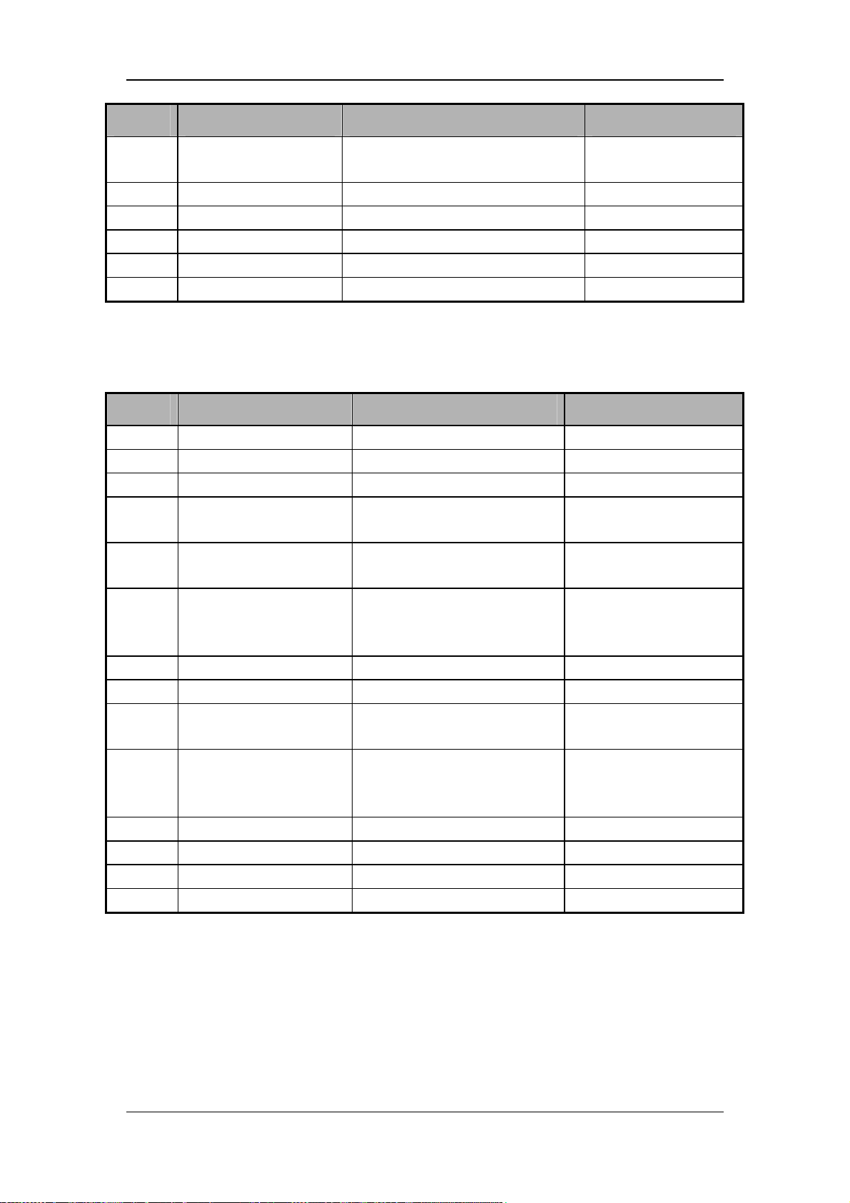
Pin No. Signal name Signal description Remark
5 5VB
6 GND Ground
7 GND Ground
8 GND Ground
9 GND Ground
10 GND Ground
J1 connector of DC-DC board is the connector with monitoring module main board. It is
defined as follows:
Pin No. Signal name Signal description Remark
1 VBUS Power supply of buzzer /
2 GND Ground
3 BELL_CTRL Control pin of buzzer
4 AC_LED
5 BAT_LED
6 TXD
7 KEY_ONOFF Power-on/off control signal
8 GND Ground
9 POWER_EN
10 RXD
11 GND Ground
12 IO1 Backup
13 GND Ground
14 GND Ground
5V power supply of GUI of
monitoring module main board
Control signal of AC indicator
light
Control signal of battery
indicator light
Serial port signal of power
board transmitting to main
control board
Control power signal of main
control board
Serial port signal of power
board receiving from main
control board
/
/
/
/
/
/
/
/
/
/
/
/
/
/
/
/
/
/
/
2-28
Page 47
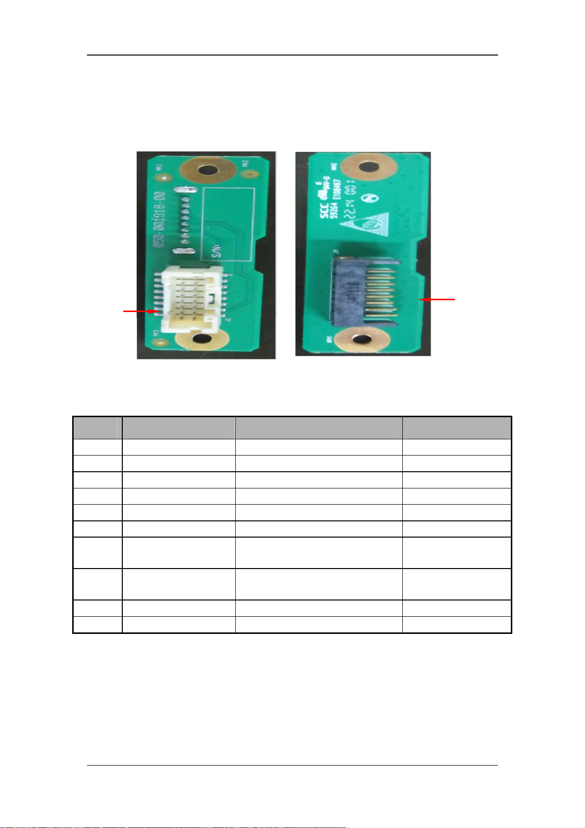
Battery adapter board:
Battery output
Battery adapter board
Battery input port
J1 connector of battery adapter board is the connector with battery. It is defined as follows:
Pin No. Signal name Signal description Remark
1 GND Ground
2 GND Ground
3 TEM Battery temperature detection signal
4 PRT_BC Battery in-place signal
5 SMBC Clock signal of battery I2C interface /
6 SMBD Data signal of battery I2C interface
7 BAT+
8 BAT+
9 GND Ground
10 GND Ground
Positive terminal of battery input
signal
Positive terminal of battery input
signal
/
/
/
/
/
/
/
/
/
2-29
Page 48
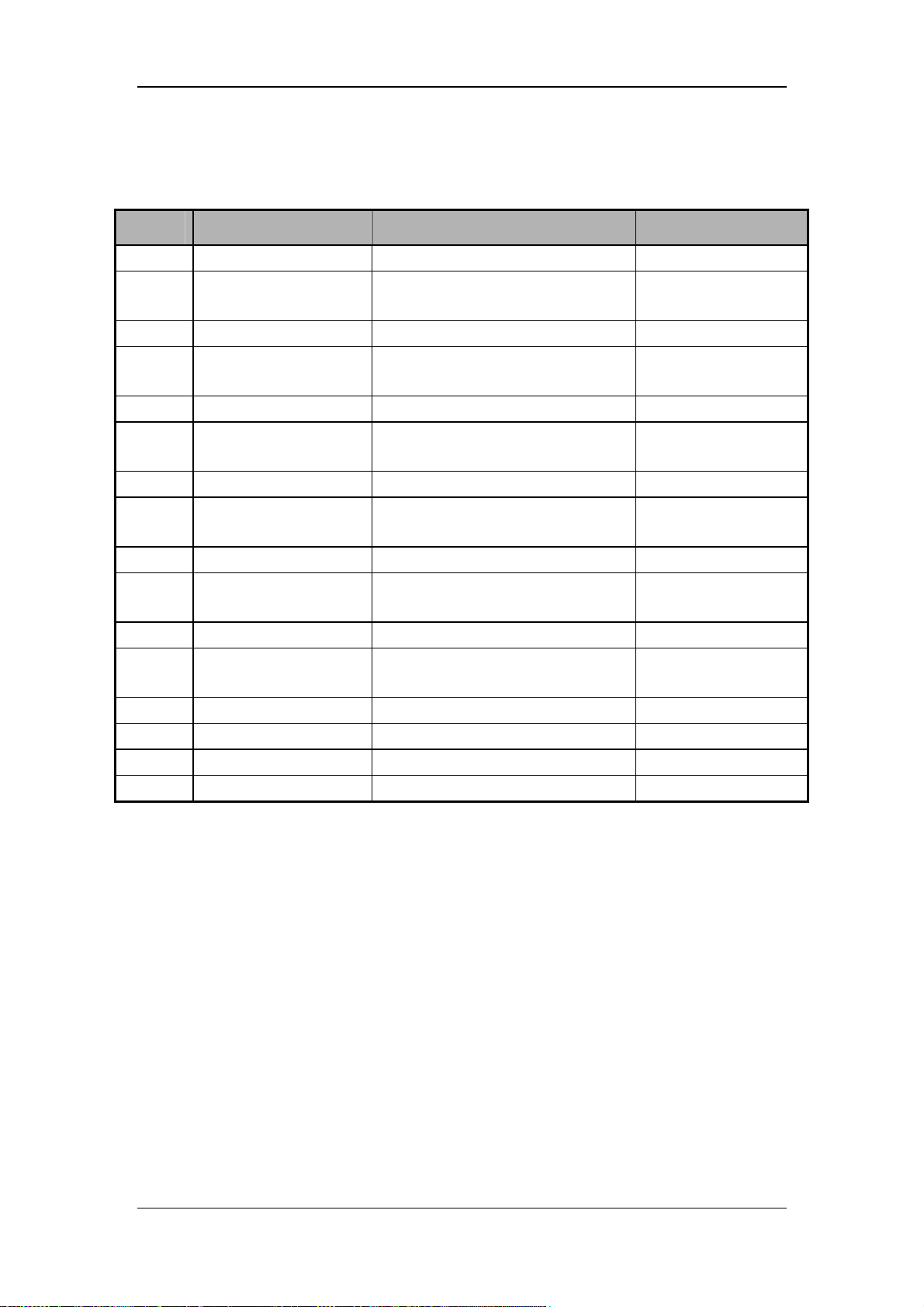
J2 connector of battery adapter board is the connector with DC-DC board. It is defined as
follows:
Pin No. Signal name Signal description Remark
1 GND Ground
2 BAT+
3 GND Ground
4 BAT+
5 GND Ground
6 BAT+
7 GND Ground
8 BAT+
9 GND Ground
10 BAT+
11 GND Ground
12 BAT+
13 TEM Battery temperature signal
14 SMBC Clock signal of battery I2C interface /
15 PRT_BC Battery in-place signal
16 SMBD Data signal of battery I2C interface
Positive terminal of battery input
signal
Positive terminal of battery input
signal
Positive terminal of battery input
signal
Positive terminal of battery input
signal
Positive terminal of battery input
signal
Positive terminal of battery input
signal
/
/
/
/
/
/
/
/
/
/
/
/
/
/
2.2.4.2 Main Control Core Board
Boards of the main control module include main control core board and peripheral interface
circuit (on the monitoring module main board). It is the control core of the ventilator and
implements man-machine interface (display screen, external key-in), control command
transfer, alarm, ventilator protection function, CO2 parameter module, and peripheral
interface circuit.
2-30
Page 49
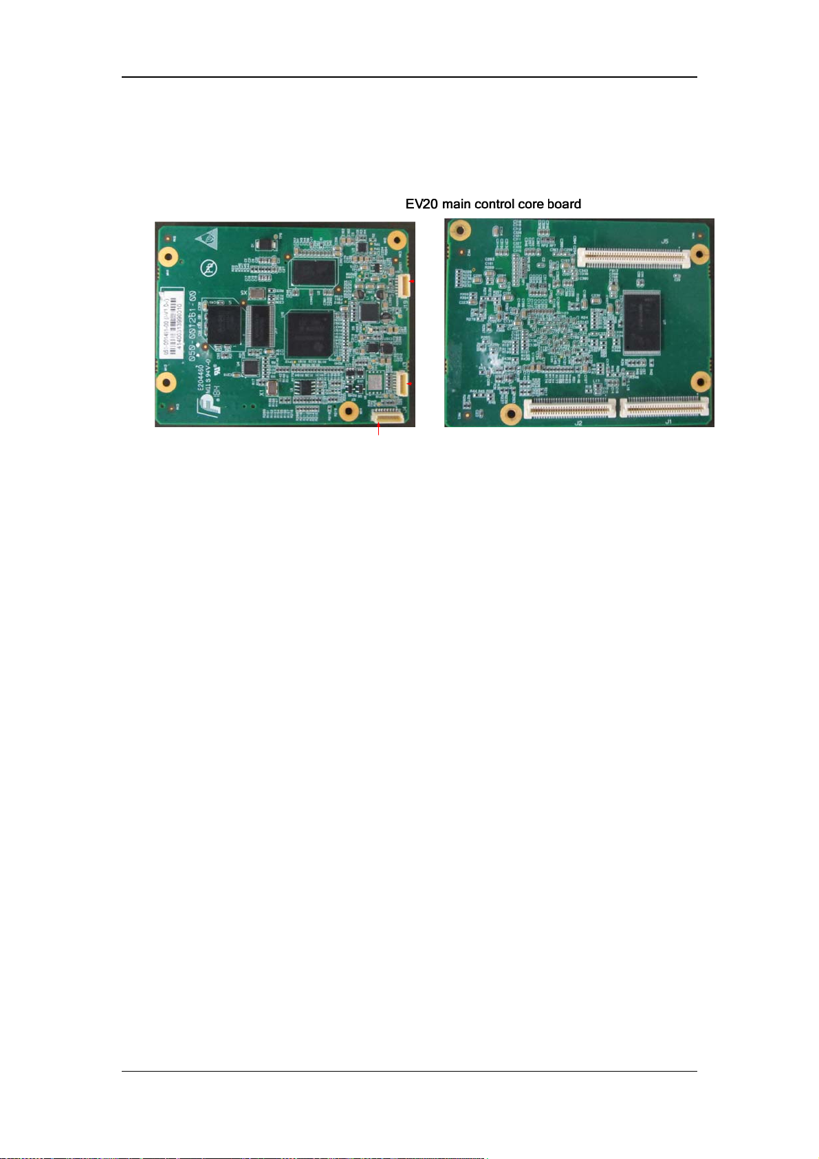
Main control core board: implements the minimum core system of the main control module;
leads out the pins of the minimum system to be connected to the monitoring main board.
Debu
ggin
g
JTAG
Serial port
2.2.4.3 Monitoring Module
The monitoring module includes the following boards: SV300/350 monitoring module main
board, SV300/350 sensor adapter board, and SV300/350 vacuum sensor board.
SV300/350 monitoring module main board:
The monitoring module main board fulfils the SV300/350 core board and ventilator
parameter functions. It includes DSP control module, inspiration module, expiration module,
and main control module peripheral interface circuit. It implements the following functions:
1. Control all valves and collect AD of analog quantity.
2. Drive and control the turbo blower.
3. Monitor turbine negative pressure and temperature.
4. Monitor pressure and flow signal input, transforms analog quantity into digital quantity.
5. Perform UART communication with the main control board.
6. Implement main control board peripheral interface circuit, such as wired network,
wireless network, USB, VGA, display interface etc.
2-31
Page 50
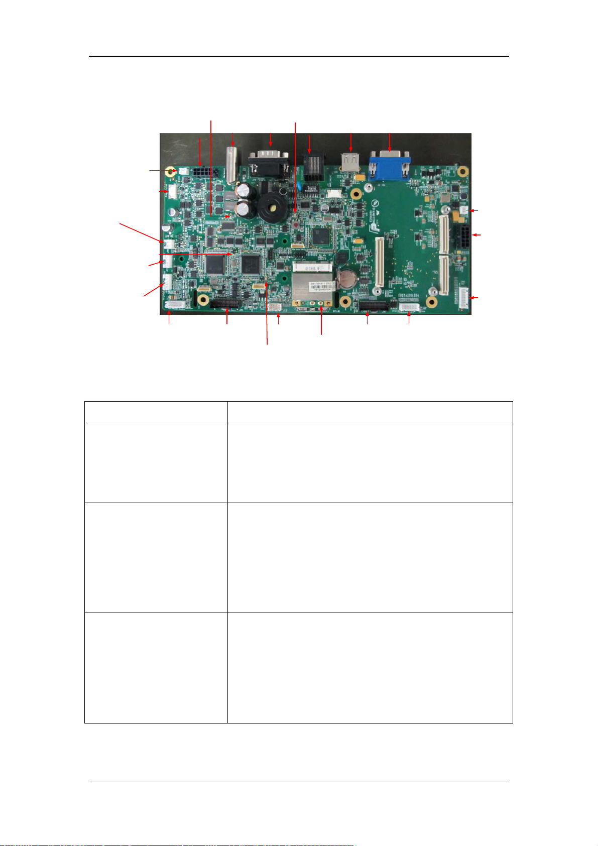
Turbine failure indicator light D1
Turbine connector
External temp.
sensor connector
Exp. Voice
coil motor
O2 proportional
valve
Insp. Failure
indicator light D2
Nebulizing
valve
Vacuum
sensor
Parameter module
connector
EV20 monitoring module main board
VCM failure indicator light D4
Nurse call RS232&CAL Net USB VGA
Sensor adapter board
connector
Exp. Failure indicator light D3
Backup(SPO2)
Display connector
Wireless wifi
Speaker
connector
Power
supply
connector
(power
board)
Signal
connector
(power
board)
Button board connector
The following table lists the indicator lights.
Item Description
Turbine failure indicator light
D1
Lit: a failure occurs to the turbo blower or drive circuit is faulty.
Check if the cable for turbine connector is properly connected. If
not, the turbo blower or monitoring module main board itself is
faulty.
No lit: operate normally.
Insp. failure indicator light D2 Lit/not lit: if the inspiration module has software failure, restart
to see if the failure disappears. If the monitoring module main
board is damaged, replace the monitoring module main board. If
the power board is faulty, enter the AD channel to see if the
voltage value which the AD value samples has an error (if an
error occurs, the value is displayed in red).
Flashing: operate normally.
Exp. failure indicator light D3 Lit/not lit: if the expiration module has software failure, restart
to see if the failure disappears. If the monitoring module main
board is damaged, replace the monitoring module main board. If
the power board is faulty, enter the AD channel to see if the
voltage value which the AD value samples has an error (if an
error occurs, the value is displayed in red).
Flashing: operate normally.
2-32
Page 51
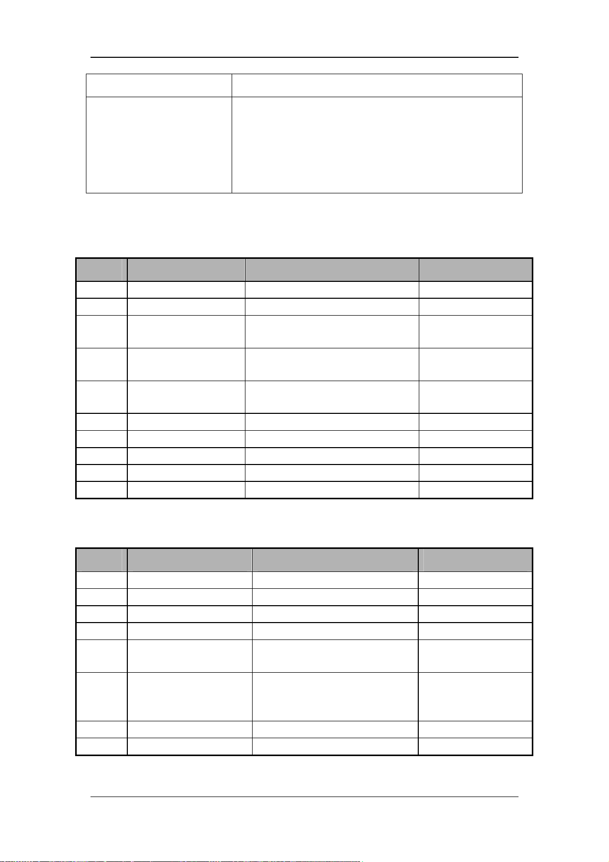
Item Description
VCM failure indictor light D4 Lit/not lit: if the VCM module has software failure, restart to see
if the failure disappears. If the monitoring module main board is
damaged, replace the monitoring module main board. If the
power board is faulty, enter the AD channel to see if the voltage
value which the AD value samples has an error.
Flashing: operate normally.
J22 connector of monitoring module main board power supply connector is the connector
with DC-DC board. It is defined as follows:
Pin No. Signal name Signal description Remark
1 VBL 24V power supply of turbo blower /
2 VBL 24V power supply of turbo blower /
3 VPP
4 VCCB
5 VCCA
6 GND Ground
7 GND Ground
8 GND Ground
9 GND Ground /
10 GND Ground
12V power supply of monitoring
module main board
5V power supply of VCM of
monitoring module main board
5V power supply of GUI of
monitoring module main board
/
/
/
/
/
/
/
J38 connector of monitoring module main board is the connector with DC-DC board. It is
defined as follows:
Pin No. Signal name Signal description Remark
1 VBUS Power supply of buzzer /
2 GND Ground
3 BELL_CTRL Control pin of buzzer
4 AC_LED Control signal of AC indicator light
5 BAT_LED
6 UART4_335X_RXD
7 PCON Power-on/off control signal
8 GND Ground
Control signal of battery indicator
light
Serial port signal of main
control board receiving from
power board
/
/
/
/
/
/
/
2-33
Page 52
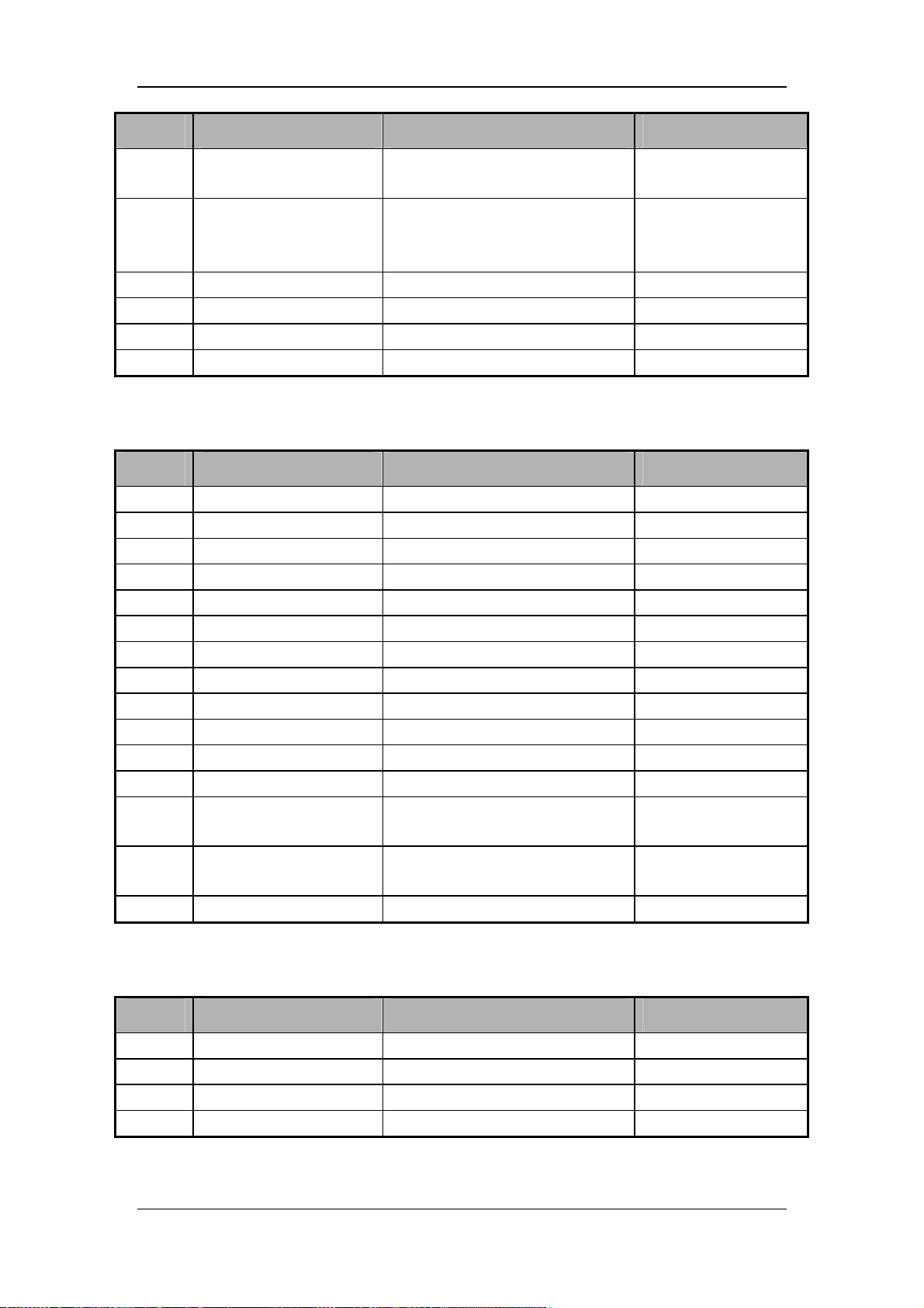
Pin No. Signal name Signal description Remark
9 POWER_EN
10 UART4_335X_TXD
11 GND Ground
12 BK Backup
13 Blank Blank
14 Blank Blank
J9 is VGA connector of external display socket. It is defined as follows:
Pin No. Signal name Signal description Remark
1 R0 R signal of external display /
2 G0 G signal of external display /
3 B0 B signal of external display /
4 NC No internal connection /
5 GND Ground /
6
7
8
9 NC No internal connection /
10 GND Ground /
11 NC No internal connection /
12 NC No internal connection /
13 LCD_HS
14 LCD_VS
15 NC No internal connection /
GND
GND
GND
Control power signal of main
control board
Serial port signal of main
control board transmitting to
power board
Ground /
Ground /
Ground /
Horizontal synchronization signal
of external display
Vertical synchronization signal of
external display
/
/
/
/
/
/
/
/
J11 is external USB connector. It is defined as follows:
Pin No. Signal name Signal description Remark
1 USB0_VBUS USB0 power supply 5V
2 USB0_DM USB0 signal cable /
3 USB0_DP USB0 signal cable /
4 GND Ground /
2-34
Page 53
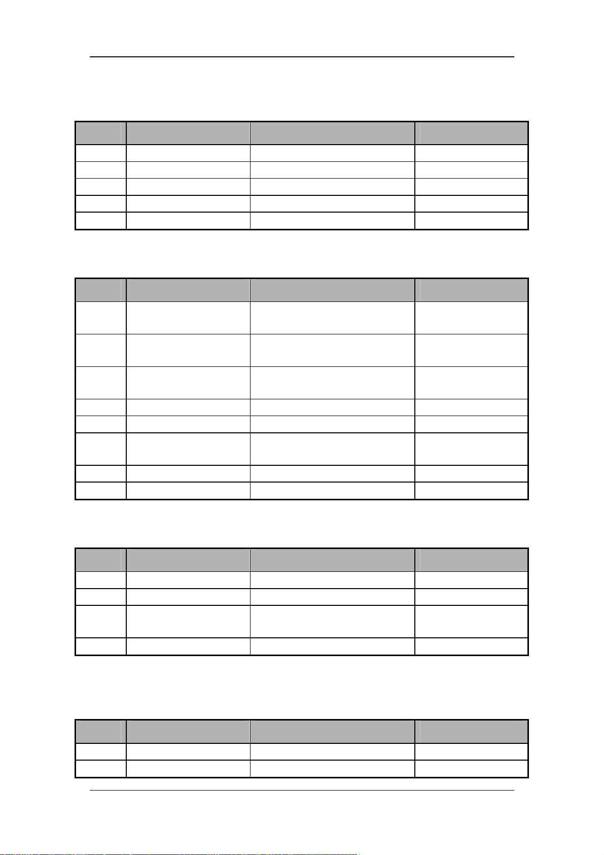
J10 is external nurse call connector. It is defined as follows:
Pin No. Signal name Signal description Remark
1 NC1 Nurse call signal /
2 GND Ground /
3 GND Ground /
4 GND Ground /
5 GND Ground /
J8 is network connector. It is defined as follows:
Pin No. Signal name Signal description Remark
1 TX+
2 TX-
3 RX+
4 GND Ground /
5 GND Ground /
6 RX-
7 GND Ground /
8 GND Ground /
J37 is nebulizing valve connector. It is defined as follows:
Pin No. Signal name Signal description Remark
1 VCCBL Nebulizing valve power supply, 5V /
2 NCV- Nebulizing valve control terminal /
3 SW_O2+
4 GND Ground /
Main control network transmitting
signal+
Main control network transmitting
signal-
Main control network receiving
signal+
Main control network receiving
signal-
Gas supply pressure switch signal,
reserved
/
/
/
/
Not used
J29 is the connector between monitoring module main board and vacuum sensor board. It is
defined as follows:
Pin No. Signal name Signal description Remark
1 V_I2C Vacuum sensor power supply, 3.3V /
2 GND Ground /
2-35
Page 54
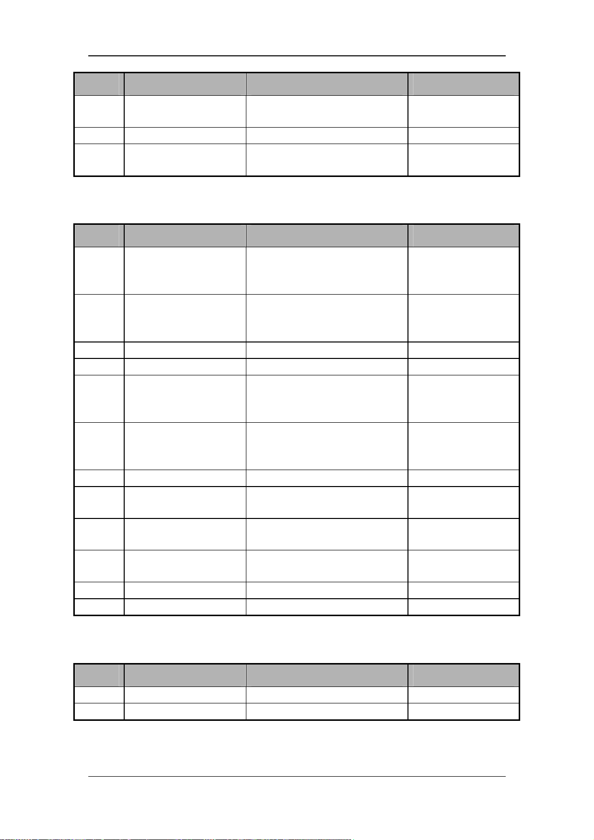
Pin No. Signal name Signal description Remark
3 AMBIENT_SDA_INSP
4 GND Ground /
5 AMBIENT_SCL_INSP
J21 is CO2 module connector. It is defined as follows:
Pin No. Signal name Signal description Remark
1 EX_5V_TXA Extension serial port transmitting
2 RS232_RXD Extension serial port receiving
3 GND Ground /
4 GND Ground /
5 EX_5V_RXA Extension serial port receiving
6 RS232_TXD Extension serial port transmitting
7 GND Ground /
8 VCCAC
9 VCCAC
10 PWR12V
11 GND Ground /
12 PWR12V CO2 module power supply, 12V /
Data line for vacuum sensor I2C
connector
Clock line for vacuum sensor I2C
connector
Mainstream CO2 module power
supply, 5V
Mainstream CO2 module power
supply, 5V
Sidestream CO2 module power
supply,12V
/
/
Communicate with the
sidestream CO2
module
Communicate with the
mainstream CO2
module
Communicate with the
sidestream CO2
module
Communicate with the
mainstream CO2
module
/
/
/
J13 is the speaker connector. It is defined as follows:
Pin No. Signal name Signal description Remark
1 VO- Speaker drive signal- /
2 VO+ Speaker drive signal + /
2-36
Page 55
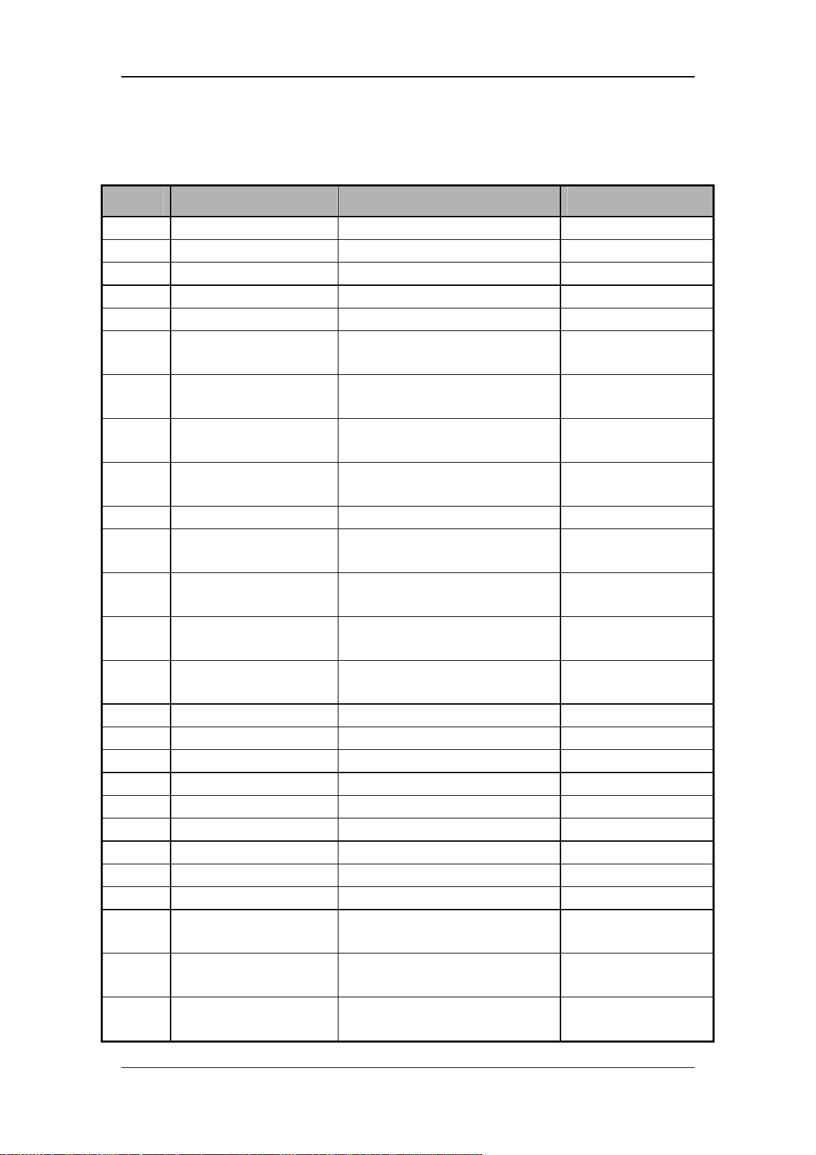
J10 is the connector between monitoring module main board and display. It is defined as
follows:
Pin No. Signal name Signal description Remark
1 GND Ground /
2 GND Ground /
3 GND Ground /
4 GND Ground /
5 GND Ground /
6 LVDS_0-
7 PWR12V
8 LVDS_0+
9 PWR12V
10 GND Ground /
11 PWR12V
12 LVDS_1-
13 PWR12V
14 LVDS_1+
15 GND Ground /
16 GND Ground /
17 GND Ground /
18 LVDS_CK- Display differential data line- /
19 VLCD Display power supply, 3.3V /
20 LVDS_CK+ Display differential data line- /
21 VLCD Display power supply, 3.3V /
22 GND Ground /
23 VLCD Display power supply, 3.3V /
24 LVDS_2-
25 PWM1
26 LVDS_2+
LVDS DIFFERENTIAL DATA
LINE0-
Display backlight power supply,
12V
LVDS DIFFERENTIAL DATA
LINE0+
Display backlight power supply,
12V
Display backlight power supply,
12V
LVDS DIFFERENTIAL DATA
LINE1-
Display backlight power supply,
12V
LVDS DIFFERENTIAL DATA
LINE1+
LVDS DIFFERENTIAL DATA
LINE2-
Backlight brightness adjustment
signal
LVDS DIFFERENTIAL DATA
LINE2+
/
/
/
/
/
/
/
/
/
2-37
Page 56
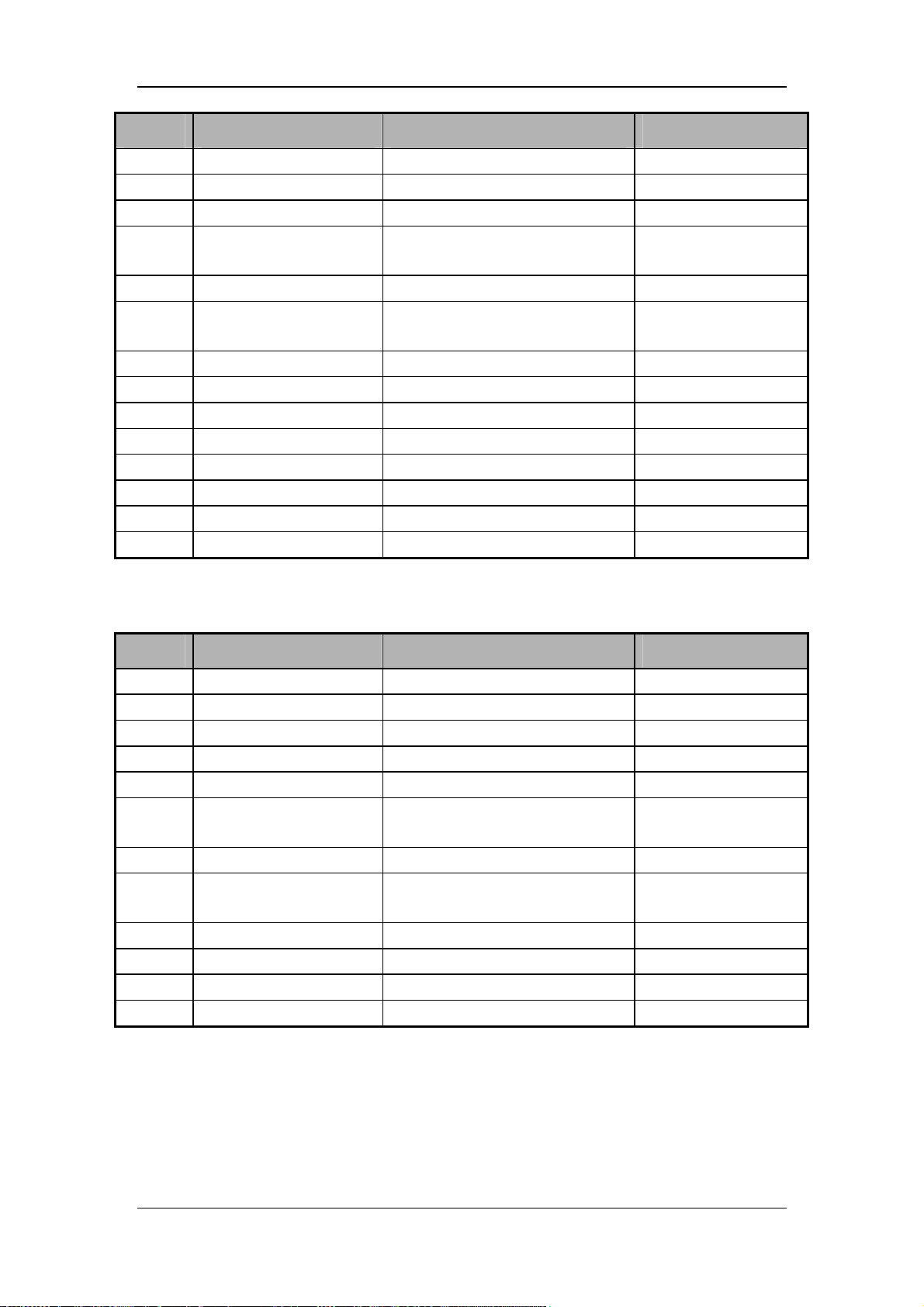
Pin No. Signal name Signal description Remark
27 GND Ground /
28 GND Ground /
29 SET_6bit/8bit Display bit color control /
30 LVDS_3-
31 BACKLIGHT_EN Display backlight enabled /
32 LVDS_3+
33 NC No internal connection /
34 GND Ground /
35 NC No internal connection /
36 GND Ground /
37 NC No internal connection /
38 NC No internal connection /
39 NC No internal connection /
40 NC No internal connection /
LVDS DIFFERENTIAL DATA
LINE3-
LVDS DIFFERENTIAL DATA
LINE3+
/
J17 is the connector between monitoring module main board and button control board. It is
defined as follows:
Pin No. Signal name Signal description Remark
1 PWR12V Button board power supply, 12V /
2 VCCA Button board power supply, 5V /
3 GND Ground /
4 VDDA Button board power supply, 3.3V /
5 GND Ground
6 UART2_335X_TXD
7 GND Ground /
8 UART2_335X_RXD
9 AC_LED AC indicator light /
10 BAT_LED Battery indicator light /
11 PCON Power-on signal /
12 GND Ground /
Button board communication serial
port, main control transmitting
Button board communication serial
port, main control receiving
/
/
2-38
Page 57
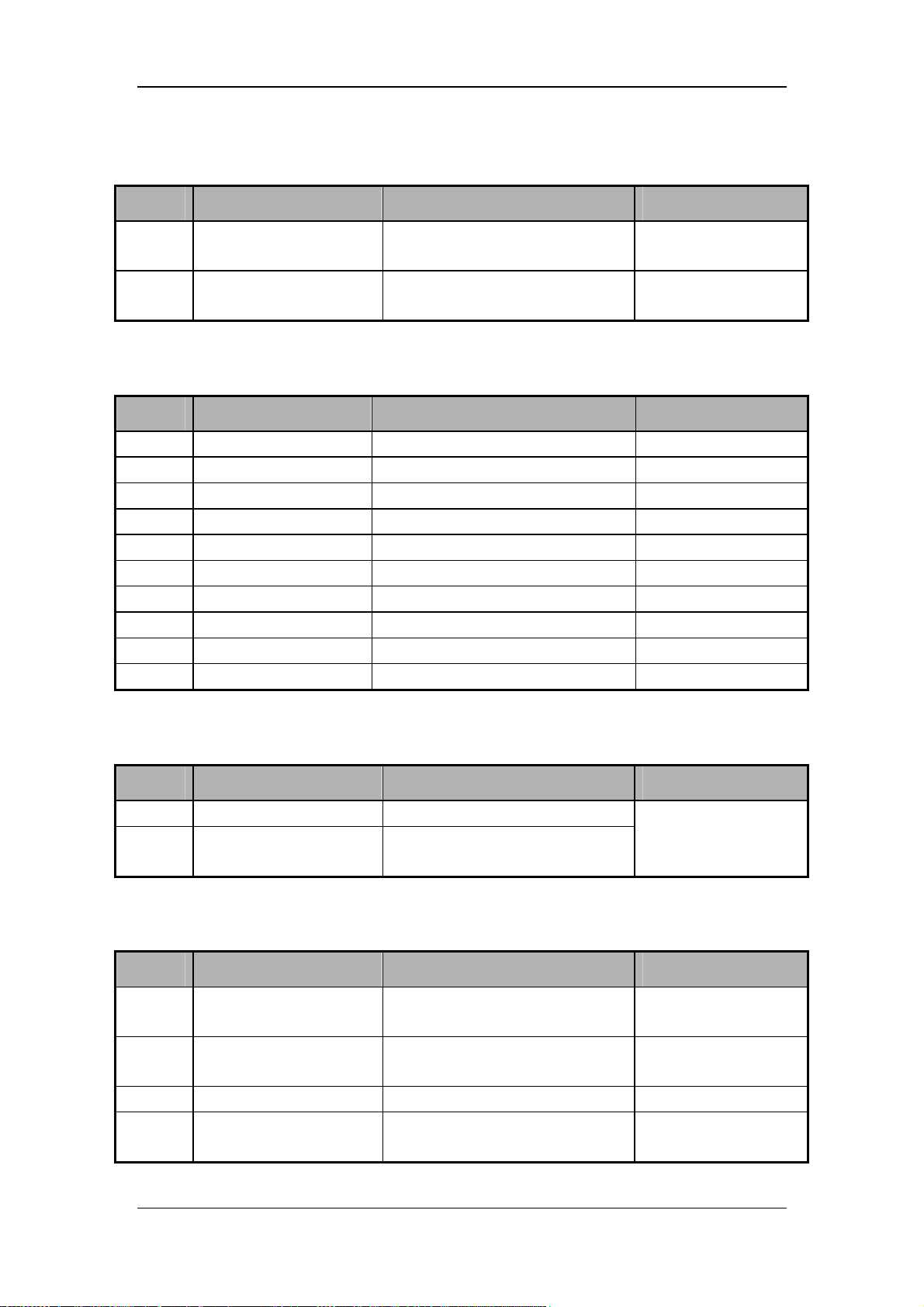
J30 is the O2 proportional valve connector. It is defined as follows:
Pin No. Signal name Signal description Remark
1 O2_Valve+
2 O2_Valve-
J1 is the turbo blower connector. It is defined as follows:
Pin No. Signal name Signal description Remark
1 H2 Hall position signal H2 /
2 H1 Hall position signal H1 /
3 VCCB Hall sensor power supply
4 MOTOR_A Turbo blower drive signal A
5 NTC1 Thermistor /
6 H3 Hall position signal H3
7 GND Ground
8 MOTOR_C Turbo blower drive signal C
9 MOTOR_B Turbo blower drive signal B
10 NTC21 Ground
Positive terminal of O2
proportional valve
Negative terminal of O2
proportional valve
/
/
/
/
/
/
/
/
/
J2 is the connector for turbo blower external temperature sensor. It is defined as follows:
Pin No. Signal name Signal description Remark
1 NTC+ One terminal of temperature sensor
2 NTC+
J31 is the connector for proportional valve. It is defined as follows:
Pin No. Signal name Signal description Remark
1 Insp_Valve+
2 Insp_Valve+
3 / / Suspended
4 Insp_Valve-
The other terminal of temperature
sensor
Positive terminal of inspiration
proportional valve
Positive terminal of inspiration
proportional valve
Negative terminal of inspiration
proportional valve
No positive and
negative terminals are
differentiated.
/
/
/
2-39
Page 58
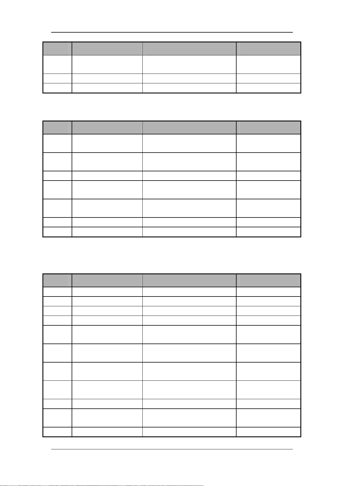
Pin No. Signal name Signal description Remark
5 Insp_Valve-
6 GND Ground Fix pad pin
7 GND Ground Fix pad pin
J32 is the connector for expiratory valve. It is defined as follows:
Pin No. Signal name Signal description Remark
1 Exp_Valve+
2 Exp_Valve+
3 NC / Suspended
4 Exp_Valve-
5 Exp_Valve-
6 GND Ground /
7 GND Ground /
Negative terminal of inspiration
proportional valve
Positive terminal of expiration
proportional valve
Positive terminal of expiration
proportional valve
Negative terminal of expiration
proportional valve
Negative terminal of expiration
proportional valve
/
/
/
/
/
J35 is the connector between monitoring module main board and sensor adapter board. It is
defined as follows:
Pin No. Signal name Signal description Remark
1 Safety_Valve- Negative terminal of safety valve /
2 Safety_Valve- Negative terminal of safety valve /
3 V_Safety_Valve Safety valve power voltage 12V
4 V_Safety_Valve Safety valve power voltage 12V
5 3Way_Purge_1_Exp-
6 3Way_Purge_2_Exp-
7 3Way_Zero_1_Exp-
8 3Way_Zero_2_Exp-
9 VCCBL Power supply 5V
10 3Way_Zero_Insp-
11 VCCBL Power supply 5V
Control signal of expiratory
purging 3-way valve 1
Control signal of expiratory
purging 3-way valve 2
Control signal of expiratory zeroing
3-way valve 1
Control signal of expiratory zeroing
3-way valve 2
Control signal of inspiratory
zeroing 3-way valve
/
/
/
/
/
2-40
Page 59
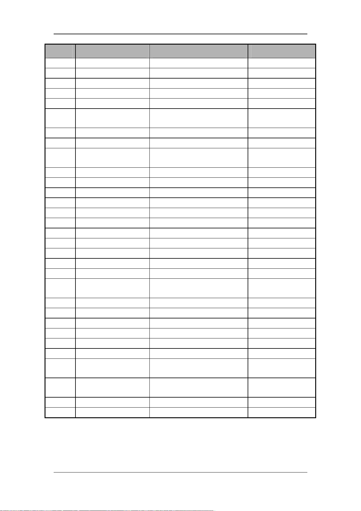
Pin No. Signal name Signal description Remark
12 GND Ground /
13 Blank / /
14 Blank / /
15 O2_TSI_SCL Clock signal of O2 TSI sensor /
16 GND Ground /
17 INSP_TSI_SCL
18 O2_TSI_SDA Data signal of O2 TSI sensor /
19 GND Ground /
20 INSP_TSI_SDA
21 VDDB Power supply 3.3V
22 GND Ground /
23 VCCBL Power supply 5V
24 AVSS Power supply -5V
25 GND Ground /
26 AVCC Power supply 5V
27 VC Power supply 10.5V
28 GND Ground /
29 EXP_PIN Expiratory pressure /
30 EXP_FIN Expiratory flow /
31 GND Ground /
32 TEMP_O2_TSI
33 FLOW_O2_TSI Flow signal of O2 TSI sensor /
34 GND Ground /
35 FiO2 Inspired O2 concentration /
36 INSP_PIN Inspiratory pressure /
37 GND Ground /
38 GND Ground /
39 FLOW_INSP_TSI
40 TEMP_INSP_TSI
41 GND Ground Fix pad pin
42 GND Ground Fix pad pin
Clock signal of mixed gas TSI
sensor
Data signal of mixed gas TSI
sensor
Temperature signal of O2 TSI
sensor
Flow signal of mixed gas TSI
sensor
Temperature signal of mixed gas
TSI sensor
/
/
/
/
/
2-41
Page 60
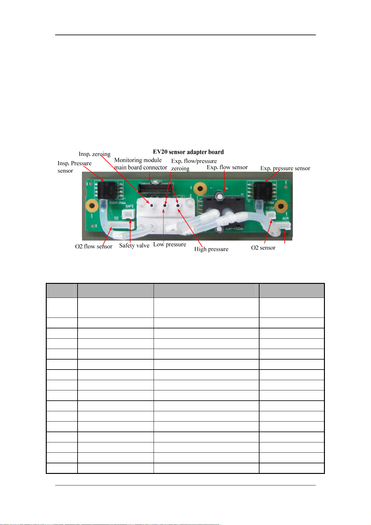
SV300/350 sensor adapter board:
The adapter board implements the following functions:
Monitor inspiratory pressure and expiratory pressure, output amplified signals.
Monitor expiratory flow and output amplified signals.
Monitor O2 concentration and output amplified signals.
Transfer O2 flow and inspiratory flow signals.
Transfer to 3-way valve.
Transfer to safety valve control signal.
J3 is the connector between sensor adapter board and monitoring module main board. It is
defined as follows:
Pin No. Signal name Signal description Remark
1 TEMP_INSP_TSI
2 FLOW_INSP_TSI Flow signal of mixed gas TSI sensor /
3 GND Ground /
4 GND Ground /
5 INSP_PIN Inspiratory pressure /
6 FiO2 O2 concentration /
7 GND Ground /
8 FLOW_O2_TSI Flow signal of O2 TSI sensor /
9 TEMP_O2_TSI Temperature signal of O2 TSI sensor /
10 GND Ground /
11 EXP_FIN Expiratory flow /
12 EXP_PIN Expiratory pressure /
13 GND Ground /
14 VC Power supply 10.5V
15 AVCC Power supply 5V
16 GND Ground /
Temperature signal of mixed gas TSI
sensor
/
2-42
Page 61
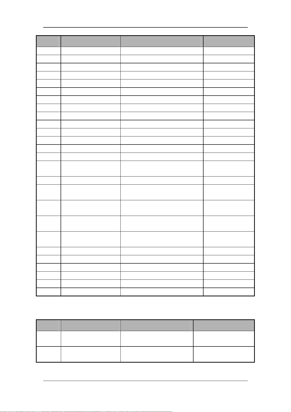
Pin No. Signal name Signal description Remark
17 AVSS Power supply -5V
18 VCCBL Power supply 5V
19 GND Ground /
20 VDDB Power supply 3.3V
21 INSP_TSI_SDA Data signal of mixed gas TSI sensor /
22 GND Ground /
23 O2_TSI_SDA Data signal of O2 TSI sensor /
24 INSP_TSI_SCL Clock signal of mixed gas TSI sensor /
25 GND Ground /
26 O2_TSI_SCL Clock signal of O2 TSI sensor /
27 Blank / /
28 Blank / /
29 GND Ground /
30 VCCBL Power supply 5V
31 3Way_Zero_Insp-
32 VCCBL Power supply 5V
33 3Way_Zero_2_Exp-
34 3Way_Zero_1_Exp-
35 3Way_Purge_2_Exp-
36 3Way_Purge_1_Exp-
37 V_Safety_Valve Safety valve power voltage 12V
38 V_Safety_Valve Safety valve power voltage /
39 Safety_Valve- Negative terminal of safety valve /
40 Safety_Valve- Negative terminal of safety valve /
41 GND Ground Fix pad pin
42 GND Ground Fix pad pin
Control signal of inspiratory zeroing
3-way valve
Control signal of expiratory zeroing
3-way valve 2
Control signal of expiratory zeroing
3-way valve 1
Control signal of expiratory purging
3-way valve 2
Control signal of expiratory purging
3-way valve 1
/
未用
/
/
/
J1 is connector for O2 concentration sensor. It is defined as follows:
Pin No. Signal name Signal description Remark
1 O2_SENSOR+
2 O2_SENSOR-
Positive terminal of O2
concentration sensor
Negative terminal of O2
concentration sensor
2-43
/
/
Page 62
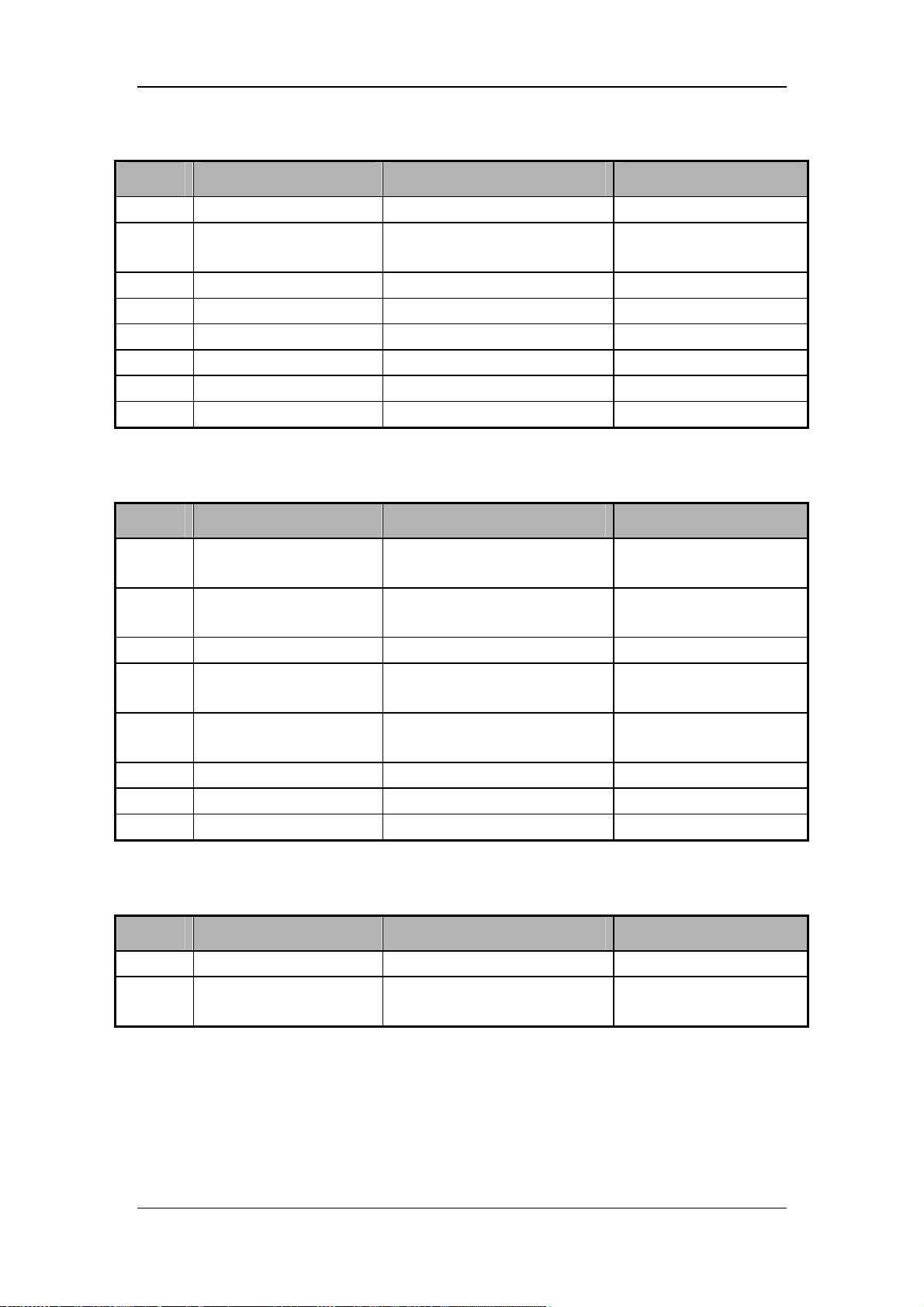
J4 is the connector for O2 flow sensor. It is defined as follows:
Pin No. Signal name Signal description Remark
1 O2_FLOW_TSI Flow signal of O2 TSI sensor /
2 O2_TEMP_TSI
3 GND Ground
4 O2_SCL_I2C_TSI Clock signal of O2 TSI sensor
5 O2_SDA_I2C_TSI Data signal of O2 TSI sensor
6 VCCBL Power supply
7 GND Ground
8 VDDB EEPROM power supply /
J5 is the connector for mixed gas flow sensor. It is defined as follows:
Pin No. Signal name Signal description Remark
Temperature signal of O2 TSI
sensor
/
/
/
/
/
/
1 INSP_FLOW_TSI
2 INSP_TEMP_TSI
3 GND Ground
4 INSP_SCL_I2C_TSI
5 INSP_SDA_I2C_TSI
6 VCCBL Power supply
7 GND Ground
8 VDDB EEPROM power supply /
J2 is the connector for safety valve. It is defined as follows:
Pin No. Signal name Signal description Remark
1 V_SAFE_VALVE Positive terminal of safety valve /
2 SAFE_VALVE-
Flow signal of mixed gas TSI
sensor
Temperature signal of mixed
gas TSI sensor
Clock signal of mixed gas TSI
sensor
Data signal of mixed gas TSI
sensor
Negative terminal of safety
valve
/
/
/
/
/
/
/
/
2-44
Page 63
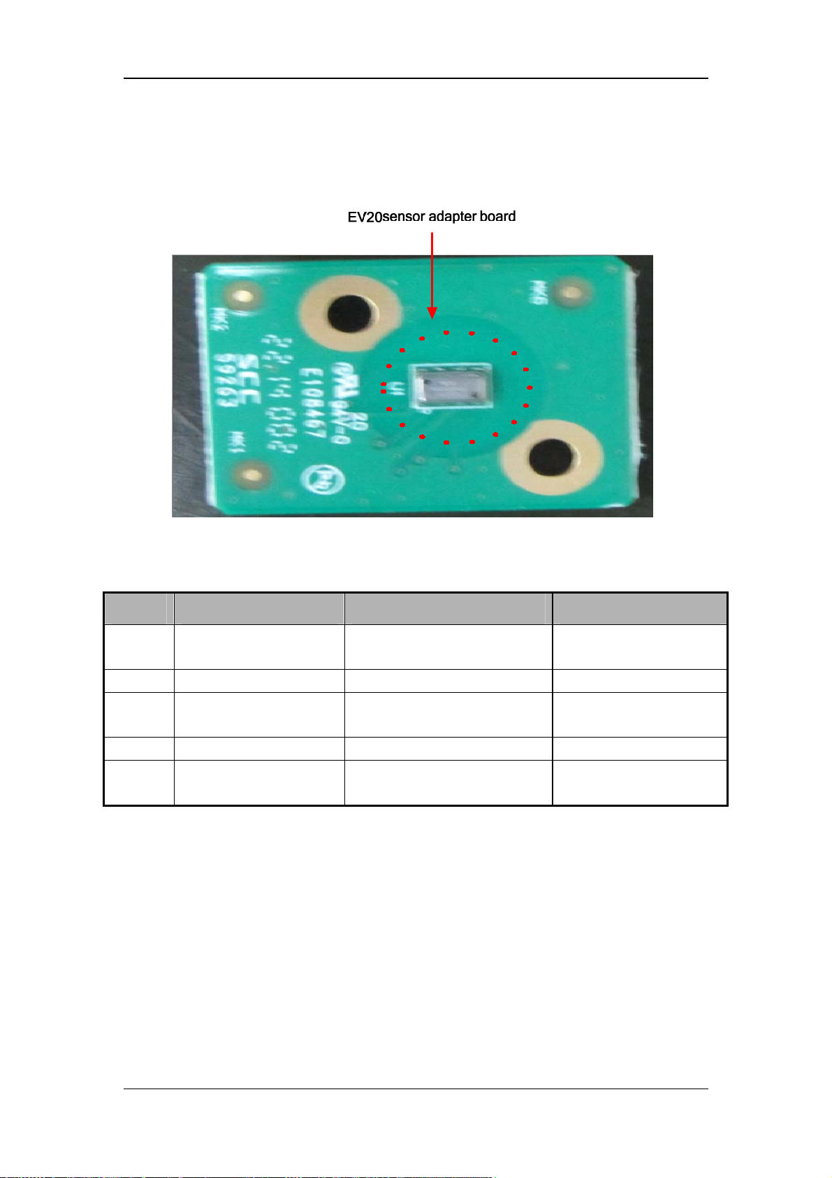
SV300/350 vacuum sensor board:
This board measures the negative pressure at the turbo blower. If the turbine inlet is occluded,
a relevant alarm is given.
J1 is the connector for vacuum sensor adapter board. It is defined as follows:
Pin No. Signal name Signal description Remark
1 V_I2C
2 GND Ground /
3 AMBIENT_SDA_INSP
4 GND Ground /
5 AMBIENT_SCL_INSP
Vacuum sensor power supply,
3.3V
Data line of vacuum sensor I2C
connector
Clock line of vacuum sensor
I2C connector
/
/
/
2.2.4.4 Display Module
Boards of the display part are responsible for man-machine interaction. They include button
control main board, alarm light board, and encoder board.
Button control main board
1. Process button input and encoder input
2. Drive alarm light and indicator light (battery and AC).
3. Perform UART communication with the main control board.
4. Process touchscreen input.
5. Provide buttons for power-on/off and silence.
2-45
Page 64
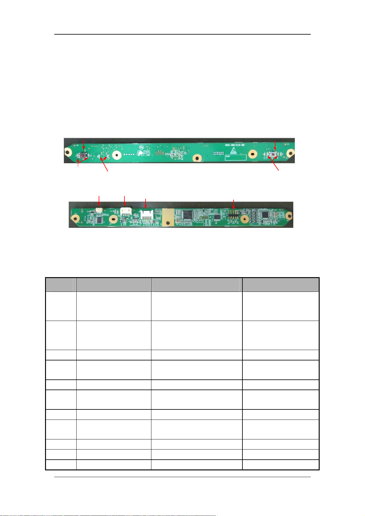
Alarm light board
Support alarm display in red and yellow.
Encoder board
1. Select and confirm touch buttons on the SV300/350 ventilator display.
SV300/350 button control main board:
Power-on/off button
Power-on/off
backlight
AC and BAT indicator lights
Encoder
connector
Alarm light
connector
Monitoring module
main board connector
Button control board
Touchscreen input port
Alarm silence button
Alarm silence indicator light
J3 is the connector between button control board and monitoring module main board. It is
defined as follows:
Pin No. Signal name Signal description Remark
Provide power supply for
1 VPP 12V power supply
alarm light and alarm
silence indicator light
Provide power supply for
2 VCC 5V power supply
touchscreen control IC and
encoder part
3 GND Ground /
4 VDD 3.3V power supply
Provide power supply for
button control CPU part
5 GND Ground /
6 TXD_MAIN
Button control serial port
receiving
TTL/LVTTL
7 GND Ground /
8 RXD_MAIN
Button control serial port
transmitting
TTL/LVTTL
9 LED_AC Signal of AC indicator light /
10 LED_BAT Signal of battery indicator light /
11 PCON Signal of power-on/off button /
2-46
Page 65
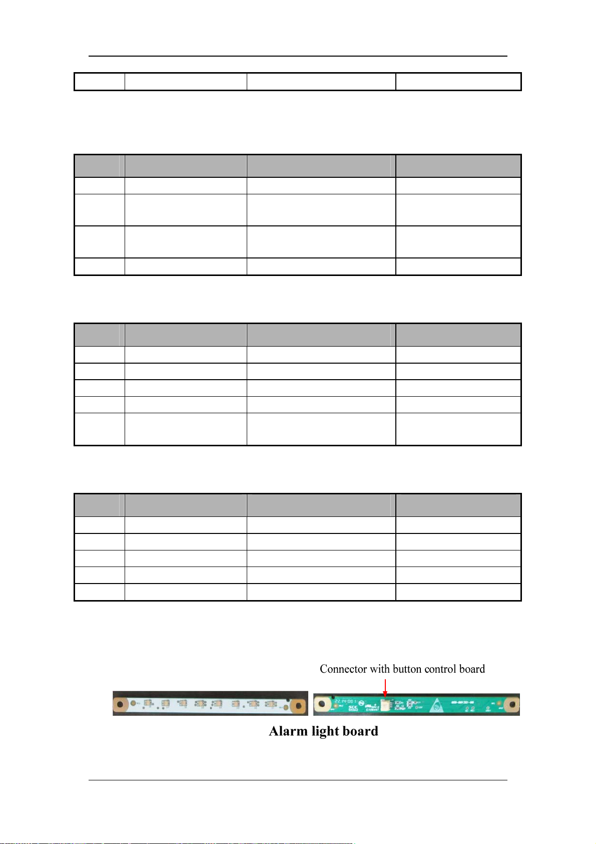
12 GND Ground /
J1 is the connector between button control board and alarm light board. It is defined as
follows:
Pin No. Signal name Signal description Remark
1 LED_RED Control signal of red alarm light
2 LED_YELLOW
3 VPP 12V power supply
4 GND Ground /
J1 is the connector between button control board and encoder board. It is defined as follows:
Pin No. Signal name Signal description Remark
1 GND Ground /
2 ES Encoder press-down
3 EB Encoder output B
4 EA Encoder output A
5 VCC 5.0V power supply
J4 is the connector between button control board and encoder board. It is defined as follows:
Control signal of yellow alarm
light
/
/
Alarm light 12V power
supply
/
/
/
Encoder power supply
5.0V
Pin No. Signal name Signal description Remark
1 UR_HIN Touchscreen RT signal /
2 XR_XLIN Touchscreen RL signal
3 AD3IN Touchscreen SG signal
4 UL_YTIN Touchscreen LT signal
5 LL_YBIN Touchscreen LL signal
/
/
/
/
SV300/350 alarm light board:
2-47
Page 66

J1 is the connector between alarm light board and button control board. It is defined as
follows:
Pin No. Signal name Signal description Remark
1 LED_RED Control signal of red alarm light
2 LED_YELLOW Control signal of red alarm light
3 VPP 12V power supply
/
/
Alarm light 12V power
supply
2-48
Page 67

3 Checkout and Test
WARNING
After servicing the equipment or replacing its components, compelete all the tests in
this section.
Before doing the tests in this section, completely reassemble the equipment and refer to
5 Maintenance and Calibration to do necessary calibrations.
3.1 System Inspection
NOTE
Make sure that the breathing system is correctly connected and not damaged.
Make sure that:
1. The equipment is not damaged.
2. All components are correctly attached.
3. The breathing system (including the inspiratory safety valve, expiration valve,
humidifier, and nebulizer etc.) is correctly connected and the breathing tubes are not
damaged.
4. The gas supplies are correctly connected and the pressures are correct.
5. Cylinder valves are closed on models with cylinder supplies.
6. The casters are not loose and the brake (s) is set and prevents movement.
7. The power cord is correctly connected. The external power indicator and the battery
indicator work normally.
8. The ventilator is switched on or off normally.
3.2 Power Failure Alarm Test (External Power and
Buzzer)
1. Connect the ventilator to the power supply. Both the power indicator and battery
indicator should come on. If the power indicator is not lit, check the fuse and power
board.
2. Depress the power switch to turn on the ventilator.
3. Disconnect the power socket with the system turned on. The prompt message [Battery
in Use] is displayed in the system alarm message area. Meanwhile, the power indicator
is extinguished and the battery indicator is flashing.
4. Reconnect the power supply and the prompt message [Battery in Use] disappears. The
power indicator is lit. The battery indicator stops flashing and stays on.
5. Remove the battery from the ventilator, and disconnect the power socket. The ventilator
will shut down and the buzzer buzz for more than 120 seconds. If the buzzer does not
respond, replace the monitoring board main board.
3-1
Page 68

3.3 O2 Pipeline Test
1. Connect the O2 pipeline supply.
2. Connect the test lungs.
3. Depress the system switch to turn on the ventilator.
4. Select [New Adult] in standby mode. Set ventilation type to [Non-invasive] and O2%
to 40%. Then select [Start Ventilation] to allow the ventilator to enter ventilation
status.
5. Make sure that the ventilator ventilates normally.
6. Disconnect the O2 pipeline supply.
7. As O2 pressure decreases, the high level alarm [O2 Supply Failure] is triggered.
3.4 System Test
1. Enter system check:
Enter system check screen after power-on. Connect O2 supply and block the Y
piece as prompted. Then select [Continue] to start system check item by item.
Push the [Standby] key. Standby screen appears after your confirmation. The
standby screen displays last system check time and result. Select [System Check].
Connect O2 supply and block the Y piece as prompted. Select [Continue] to start
system check item by item.
2. System check items include:
Blower test: test the rotation speed of the blower ;
O2 flow sensor test: test the flow sensor in O2 limb ;
Insp. flow sensor test : test the inspiratory valve and flow sensor ;
Exp. flow sensor test : test the expiratory flow sensor ;
Pressure sensor test: test the pressure sensors at the inspiratory and expiratory
ports;
Expiratory valve test ;
Safety valve test;
Leakage (mL/min) ;
Compliance (mL/cmH2O) ;
Circuit resistance (cmH2O/L/s) ;
O2 sensor test.
3. System check result can be:
Pass: indicates that check of this item is completed and is passed.
Fail: indicates that check of this item is not completed and is failed.
Cancel: indicates that check of this item is not completed;
O2 Supply Failure : indicates that O2 supply is insufficient when O2 flow sensor
test and O2 sensor test are being carried out;
Monitoring Off : indicates that O2 concentration monitoring function may not be
switched on when O2 sensor test is being carried out.
4. When system check is being performed, the system prompts [Running] on the right side
of the current check item. In this case, if you select [Skip], the system stops check of
this item immediately and displays [Cancel]. Check of the next item begins at the same
time. If you select [Stop], the system stops check of the current item and also check of
the remaining items, and displays [Cancel].
3-2
Page 69

5. When checks of all items are completed, if you select [Retry], the system starts a new
round of check. When [Exit] is selected, the system exits check and enters standby
screen
6. Make sure that all the [Syst. Check] items pass the test.
3.5 Spontaneous Breathing Test
1. Turn off the ventilator and let the ventilator in OFF state. Wear a mask, and check if the
spontaneous breathing is smooth.
2. Turn on the ventilator and let the ventilator in Standby state. Wear a mask, and check if
the spontaneous breathing is smooth.
3.6 Humidifier Performance Test
For detailed performance test information, please refer to the Instructions for Use of the
humidifier. Make sure that the humidifier works normally.
3.7 Alarm Tests
3.7.1 Prepare for Alarm Tests
1. Connect test lungs to the Y piece patient connection.
2. Turn on the ventilator. Select [New Adult] in standby mode. Set ventilation type to
[Invasive].
3. Set the ventilator controls as follows (in standard working state):
Ventilator mode: [V-A/C]
O2 concentration [O2%]: 40%
Tidal volume [TV]: 500 ml
Inspiration time [Tinsp]:2s,or Inspiration and expiration ratio [I :E]:1 :2
Frequency [f]:10 bpm
Positive end-expiratory pressure [PEEP]: 3 cmH2O
Note: the working mode of the ventilator in this chapter refers to standard working state
unless specified otherwise.
4. Set the ventilator to exit standby state and enter working state.
5. Make sure of:
Normal display of the ventilator monitored parameter data
Periodical inspiraton and expiration of the test lungs.
3.7.2 Battery in Use Alarm Test
1. Connect the ventilator to AC power and depress the hardkey.
2. Disconnect the AC power after the system starts up.
3. Verify that the [Battery in Use] alarm is activated and the ventilator is powered by the
battery.
4. Re-connect the AC power.
5. Verify that this alarm is automatically reset and the ventilator is AC powered.
3-3
Page 70

3.7.3 Power Failure Alarm Test
1. Connect the AC power and depress the hardkey to start up the ventilator.
2. Disconnect the AC power after the battery is fully charged.
3. Connect the test lungs to let the ventilator keep normal ventilation.
4. For the ventilator configured with one battery, the ventilation time is approximately 2
hours (for the ventilator configured with two batteries, the ventilation time is
approximately 4 hours). When the battery capacity is to be depleted, verify that the
[System DOWN. Connect AC.] alarm is activated.
5. Re-connect the AC power. Verify that this alarm is automatically reset and the ventilator
is AC powered.
3.7.4 Paw Too High Alarm Test
1. After the ventilator system starts up normally, connect the ventilator to the test lungs to
start ventilation.
2. Set Paw high alarm limit to current peak pressure+5cmH2O。
3. Squeeze the test lungs forcibly in the inspiration phase.
4. Verify that the [Paw Too High] alarm is activated, breathing cycle enters expiration
phase, and Paw decreases to PEEP value.
3.7.5 TVe Too High Alarm Test
1. After the ventilator system starts up normally, connect the ventilator to the test lungs and
set to pressure mode to start ventilation.
2. Set TVe high alarm limit to be less than the current TVe to verify that the [TVe Too
High] alarm is activated.
3. Set TVe high alarm limit to be greater than the current TVe to verify that this alarm is
automatically reset.
3.7.6 TVe Too Low Alarm Test
1. After the ventilator system starts up normally, connect the ventilator to the test lungs to
start ventilation.
2. Set TVe low alarm limit to be greater than the current TVe to verify that the [TVe Too
Low] alarm is activated
3. Set TVe low alarm limit to be less than the current TVe to verify that this alarm is
automatically reset.
3.7.7 MV Too High Alarm Test
1. After the ventilator system starts up normally, connect the ventilator to the test lungs to
start ventilation.
2. Set MV high alarm limit to be less than the current MV to verify that the [MV Too
High] alarm is activated.
3. Set MV high alarm limit to be greater than the current MV to verify that this alarm is
automatically reset.
3-4
Page 71

3.7.8 MV Too Low Alarm Test
1. After the ventilator system starts up normally, connect the ventilator to the test lungs to
start ventilation.
2. Set MV low alarm limit to be greater than the current MV to verify that the [MV Too
Low] alarm is activated.
3. Set MV low alarm limit to be less than the current MV to verify that this alarm is
automatically reset.
3.7.9 PEEP Too Low Alarm Test
1. Remove the expiratory valve diaphragm of the ventilator and install the expiratory
valve.
2. After the ventilator system starts up normally, connect the ventilator to the test lungs to
start ventilation.
3. Set PEEP to 5cmH2O. Verify that the [PEEP Too Low] alarm is activated.
4. Re-install the expiratory valve diaphragm and install the expiratory valve.
5. Repeat steps 2 and 3. Verify that this alarm is automatically reset.
3.7.10 Airway Obstructed Alarm Test
1. After the ventilator system starts up normally, connect the ventilator to the test lungs and
set to pressure mode to start ventilation.
2. Nip the inspiration tube with the hands. Make sure the monitoring value of TVi is lower
than 10 ml.
3. After several breathing cycles, verify that the [Airway Obstructed?] alarm is activated.
4. Loosen the inspiration tube and verify that this alarm is automatically reset.
3.7.11 Apnea Alarm Test
1. After the ventilator system starts up normally, connect the ventilator to the test lungs to
start ventilation.
2. Set apnea alarm time to 15s.
3. Set breathing frequency to 3bpm. Verify that the [Apnea] alarm is activated.
4. Set breathing frequency to 10bpm. Verify that this alarm is automatically reset.
3.7.12 ftotal Too High Alarm Test
1. After the ventilator system starts up normally, connect the ventilator to the test lungs to
start ventilation.
2. Set ftotal high alarm limit to be less than the current ftotal. Verify that the [ftotal Too
High] alarm is activated.
3. Set ftotal high alarm limit to be greater than the current ftotal. Verify that this alarm is
automatically reset.
3-5
Page 72

3.7.13 FiO2 Too High Alarm Test
1. Connect the ventilator to low-pressure O2 supply. Select [Setup] →[Maintain]→[User]
→enter the required password→[Setting]→[Gas Supply] to set [O2 Supply Type] to
[LPO].
2. Connect the ventilator to the test lungs to start ventilation.
3. After ventilation is stable, set FiO2 high alarm limit to be less than the current O2
concentration monitored value.
4. Verify that the [FiO2 Too High] alarm is activated.
5. Set FiO2 high alarm limit to be greater than the current O2 concentration monitored
value. Verify that this alarm is automatically reset.
3.7.14 FiO2 Too Low Alarm Test
1. Connect the ventilator to high-pressure O2 supply. Select [Setup] →[Maintain]→
[User]→enter the required password→[Setting]→[Gas Supply] to set [O2 Supply
Type] to [HPO].
2. Connect the ventilator to the test lungs to start ventilation.
3. After ventilation is stable, turn off high-pressure O2 supply.
4. Verify that the [FiO2 Too Low] alarm is activated.
5. Re-connect high-pressure O2 supply. Verify that this alarm is automatically reset.
3.7.15 EtCO2 Too High Alarm Test
1. Connect the CO2 test module. Set CO2 module to working mode.
2. Connect the ventilator to the test lungs to start ventilation.
3. After CO2 completes warm-up and enters working mode, vent 3%-7% standard CO2 to
sidestream CO2.
4. At the module sampling port or the airway adapter of mainstream CO2 module, set
EtCO2 high alarm limit to be less than the standard gas concentration.
5. Verify that the [EtCO2 Too High] alarm is activated.
6. Set EtCO2 high alarm limit to be greater than the standard gas concentration. Verify that
this alarm is automatically reset.
3.7.16 EtCO2 Too Low Alarm Test
1. Connect the ventilator to the test lungs to start ventilation.
2. Connect the CO2 test module. Set CO2 module to working mode.
3. After CO2 completes warm-up and enters working mode, vent 3%-7% standard CO2 to
sidestream CO2.
4. At the module sampling port or the airway adapter of mainstream CO2 module, set
EtCO2 low alarm limit to be greater than the standard gas concentration.
5. Verify that the [EtCO2 Too Low] alarm is activated.
6. Set EtCO2 low alarm limit to be less than the standard gas concentration. Verify that
this alarm is automatically reset.
3-6
Page 73

3.7.17 SpO2 Too High Alarm Test
1. Connect the adult SpO2 sensor to the ventilator SpO2 connector. Set the ventilator
patient type to [New Adult].
2. Select [Setup]→[Sensor]→[SpO2] and set [Monitoring] to [On].
3. Measure SpO2 at your finger (supposing you are in healthy state). Set the SpO2 high
alarm limit to 80% when the ventilator is stabilized.
4. Verify that the [SpO2 Too High] alarm is activated.
5. Set the SpO2 high alarm limit to 100%. Verify that this alarm is automatically reset.
3.7.18 SpO2 Too Low Alarm Test
1. Connect the adult SpO2 sensor to the ventilator SpO2 connector. Set the ventilator
patient type to [New Adult].
2. Select [Setup]→[Sensor]→[SpO2] and set [Monitoring] to [ON].
3. Measure SpO2 at your finger (supposing you are in healthy state). Set the SpO2 low
alarm limit to 98% when the ventilator is stabilized.
4. Hold the wrist of the hand with sensor. Hold and press pulse until the SpO2 reading is
less than 98%. Verify that the [SpO2 Too Low] alarm is activated.
5. Stop pressing the pulse and set the SpO2 low alarm limit to 90%. Verify that this alarm
is automatically reset.
3.7.19 PR Too High Alarm Test
1. Connect the adult SpO2 sensor to the ventilator SpO2 connector. Set the ventilator
patient type to [New Adult].
2. Select [Setup]→[Sensor]→[SpO2] and set [Monitoring] to [ON].
3. Measure SpO2 at your finger (supposing you are in healthy state). Set the PR high alarm
limit to 40 L/min when the ventilator is stabilized.
4. Verify that the [PR Too High] alarm is activated.
5. Set the PR high alarm limit to 120 L/min. Verify that this alarm is automatically reset.
3.7.20 PR Too Low Alarm Test
1. Connect the adult SpO2 sensor to the ventilator SpO2 connector. Set the ventilator
patient type to [New Adult].
2. Select [Setup]→[Sensor]→[SpO2] and set [Monitoring] to [ON].
3. Measure SpO2 at your finger (supposing you are in healthy state). Set the PR low alarm
limit to 120 L/min when the ventilator is stabilized.
4. Verify that the [PR Too Low] alarm is activated.
5. Set the PR low alarm limit to 40 L/min. Verify that this alarm is automatically reset.
3-7
Page 74
3.8 Function Tests
3.8.1 Checking the Standard Working Mode
Turn on the power switch and make sure that the ventilator is in working mode.
Ventilator mode: [V-A/C]
O2 concentration [O2%]:40 %
Tidal volume [TV]:500 ml
Inspiration time [Tinsp]:2s,or Inspiration and expiration ratio [I :E]:1 :2
Frequency [f]:10 bpm
Positive end-expiratory pressure [PEEP]:3 cmH2O
3.8.2 Checking the Tidal Volume
Turn on the ventilator and connect the test lungs. When the tidal volume output becomes
stable, observe the tidal volume displayed on the screen. Make sure that the displayed tidal
volume monitored value is stable and the monitored value is consistent with the set value.
3.8.3 Checking the Trigger Function
1. Set the pressure trigger sensibility to -2 cmH2O. Wear a mask and inspire gently. When
the airway pressure is a bit lower than this set value, starts inspiration and the trigger
icon
2. Set the flow trigger sensibility to 2 L/min. Wear a mask and inspire slightly. When the
inspiration flow is a bit lower than this set value, starts inspiration and the trigger icon
flashes in the information bar of the screen.
flashes in the information bar of the screen.
3.8.4 Checking Spontaneous Breathing in CPAP/PSV Mode
1. Set the ventilator to CPAP/PSV mode, flow trigger to 2 L/min, pressure support level to
10 cmH
2. Wear a mask and inspire slightly. When the trigger sensitivity is reached, make sure that
inspiration starts and that the ventilator starts PSV ventilation.
O, and other parameters to their default values.
2
3.8.5 Sidestream CO2 Test and Calibration
Leak test:
1. In standby mode, occlude the gas inlet of the module or watertrap with hand or other
object after CO2 warm-up is completed.
2. After occluding the gas inlet of the module or watertrap for a period of time, the screen
displays the alarm message [CO2 Sampleline Occluded], indicating that the module
has no leaks.
3-8
Page 75
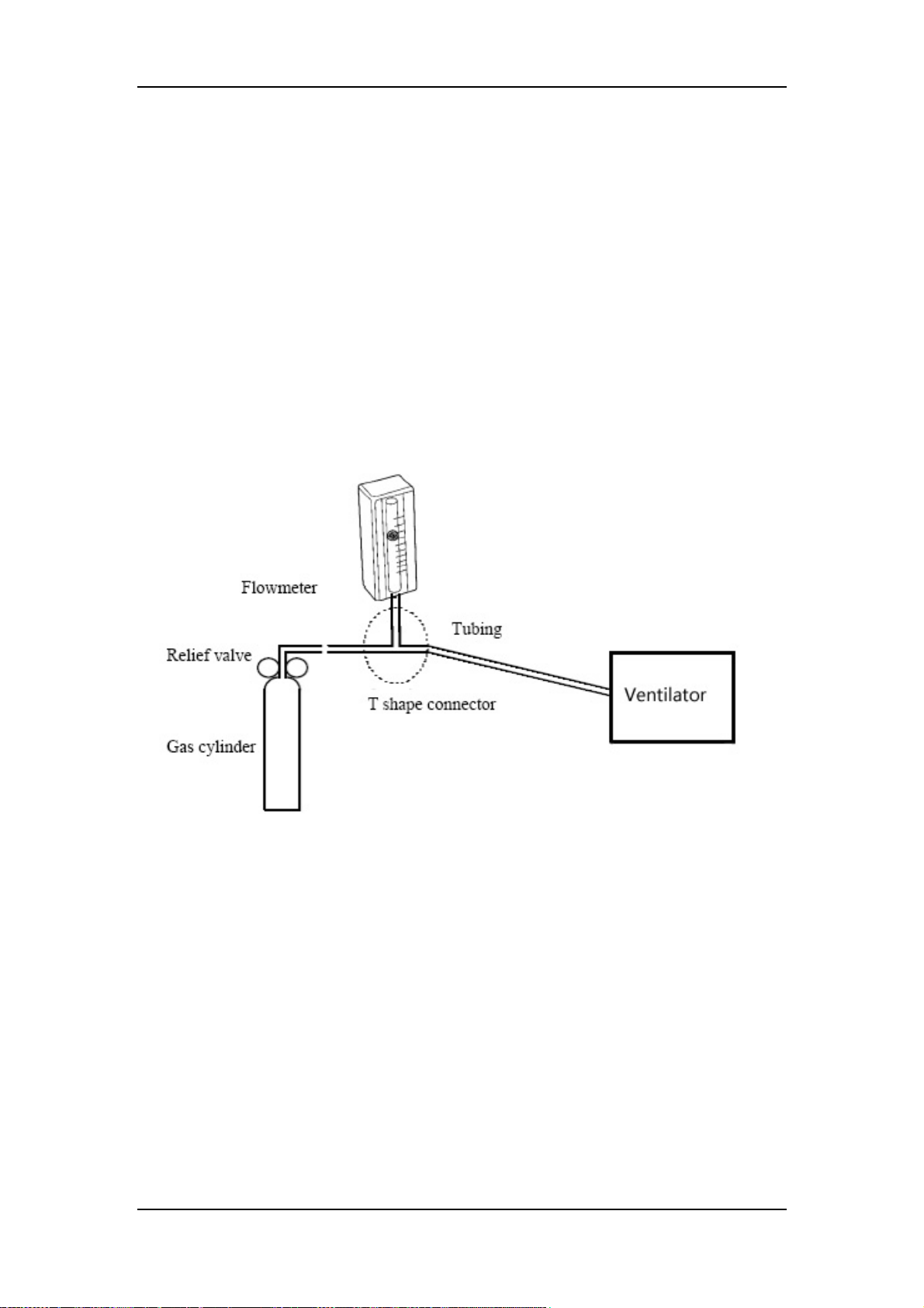
Module calibration:
Test tools:
CO2 with concentration of 6±0.05%, cylinder with N2 as balance gas
T -connector
Gas tube
Flowmeter
1. Make sure that the sidestream CO2 module has already been warmed up or started.
2. Check the airway and leakage. Make sure that there is no leakage in the airway.
3. Select [Setup]→[Maintain]→[User]→enter the required password→[CO2 In
Maintenance]→[Zero].
4. Connect as shown below after successful zeroing.
5. Turn on and adjust the regulator switch to make the flowmeter indicate flow of 10 to 50
mL/min and keep such flow.
6. Enter 6% (CO2 concentration value) in the [CO
2%] text box in the [CO2 In
Maintenance] menu.
7. After the actually measured CO2 concentration is stable, select [Calibrate] to calibrate
the CO2 module. After successful calibration, the message [CO2 % Calibration
Completed!] is displayed. If the calibration fails, the message [Calibration Failure!
Try again!] is prompted. In this case, calibrate again.
3-9
Page 76
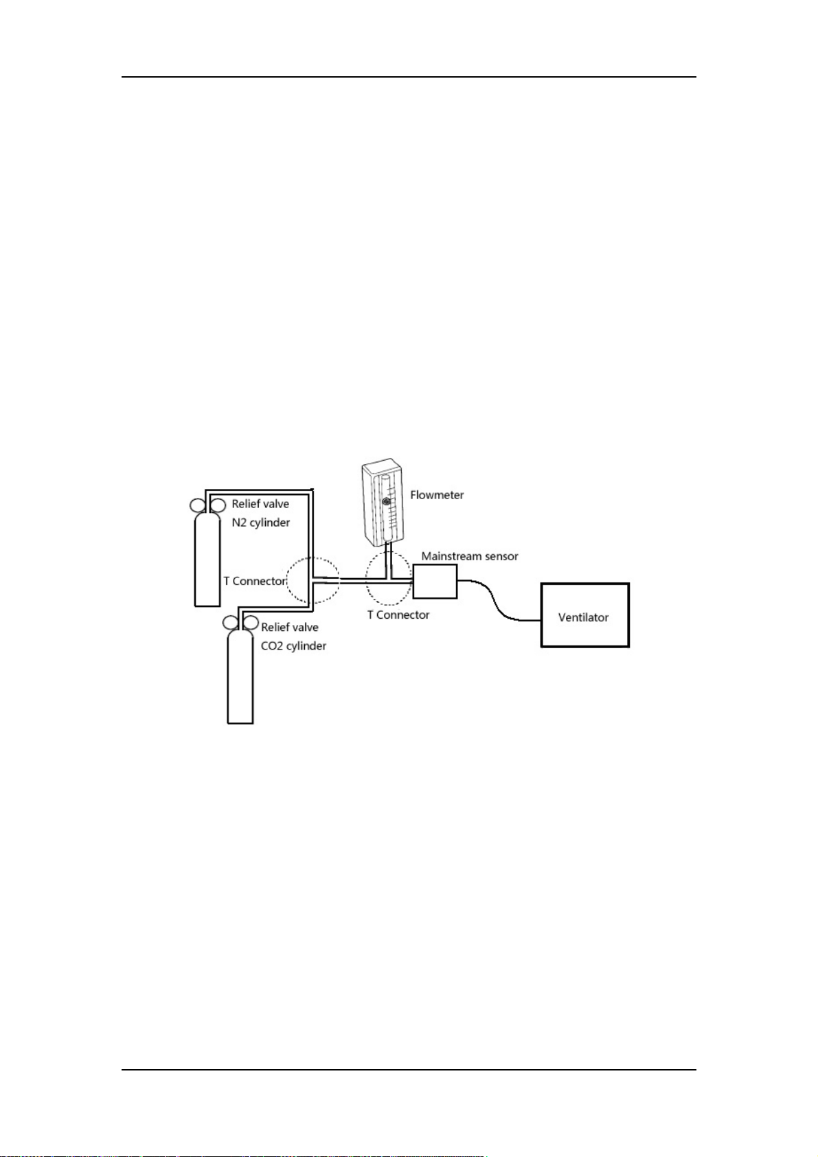
3.8.6 Mainstream CO2 Test
Test tools:
CO2 with concentration of 6±0.05%, cylinder with N2 as balance gas
Cylinder wtih 100% N2
T -connector
Gas tube
Flowmeter
1. Make sure that the mainstream CO2 module has already been warmed up or started.
2. Select [Setup]→[Calibrate]→[Zero]. Select the [Start] button corresponding to CO2
zeroing. The screen displays [CO2 Zeroing].
3. After successful zeroing, put the sensor before the mouth and breathe so that there is a
CO2 waveform on the screen. Then put the sensor in the air. Check that the ventilator
produces the alarm message [Apnea CO2].
4. Connect the test system as shown below.
5. Open the N2 cylinder and CO2 cylinder regulators. Make sure that there is only one
cylinder connected with the T-connector at a time.
6. Adjust the regulator switch to make the flowmeter indicate flow of 2~5L/min and
keep such flow.
7. Switch the cylinders connected with the T-connector at a time interval of 6-10s. Check
that the CO2 displayed value is 45±2mmHg.
3-10
Page 77

3.8.7 SpO2 Test
1. Connect the adult SpO2 sensor to the ventilator SpO2 connector. Set the ventilator
patient type to [New Adult].
2. Measure SpO2 at your finger (supposing you are in healthy state).
3. Check that the ventilator displays SpO2 Pleth waveform and PR value. And the
displayed SpO2 range should be 95-100%.
4. Remove the SpO2 sensor from the finger. Verify that the alarm [SpO2 Sensor Off] is
produced.
3.8.8 Checking the Special Functions
Inspiration Hold
1. Select the [Tools] key →[Functions] →[Insp. Hold]. Press and hold the [Insp. Hold]
key continuously. Make sure that the ventilator enters inspiration hold phase. The
ventilator automatically terminates the inspiration hold function if the [Insp. Hold] key
is pressed and held for continuous 30 seconds.
2. Release the [Insp. Hold] key, and make sure the ventilator enters expiration phase.
Expiration Hold
1. Select the [Tools] key →[Functions] →[Exp. Hold]. Press and hold the [Exp. Hold]
key continuously. Make sure that the ventilator enters expiration hold phase. The
ventilator automatically terminates the expiration hold function if the [Exp. Hold] key is
pressed and held for continuous 30 seconds.
2. Release the [Exp. Hold] key, and make sure the ventilator enters inspiration phase.
O2 Enrichment
1. When the ventilator is in working state, select Adult mode and press the [O
button. Make sure that the ventilator starts to deliver 100% O2.
2. Press the [O2↑ Suction] button again or maintain O2 enrichment function active for 2
minutes. Make sure that the ventilator restores to the working state before O2
enrichment.
Suction
1. Press the [O
the first phase; namely, O2 enrichment is active.
2. Disconnect the patient. Make sure that suction enters the second phase; namely, O2
enrichment is not active. The message [The Patient is Disconnected! Reconnect
Patient after Suction Completed!] is prompted.
3. Re-connect the patient. Make sure that suction enters the third phase; namely, O2
enrichment is active.
Nebulizer
1. When the ventilator is in working state, press the [Nebulizer] key and set [Nebulizer
Time] in the accessed menu. Then select [Ok]. Make sure that the ventilator starts
nebulizer function that there is gas output at the nebulizer output port.
2. When the nebulizer time expires or the [Nebulizer] key is pressed again, make sure that
the ventilator terminates nebulizer function.
↑ Suction] button to enter suction function. Make sure that suction enters
2
↑ Suction]
2
3-11
Page 78

Manual Breath
When the ventilator is in working state, select the [Tools] key →[Functions] →
[Manual Breath]. Make sure that the ventilator delivers mechanical ventilation
immediately.
Sigh
1. When the ventilator is in working state, select the
2. Set ventilation parameters to their default values: [△int.PEEP] to 5cmH2O, [Interval]
to 1min, and [Cycles Sign] to 3.
3. Select [Ok]. Make sure that the ventilator activates sigh function once every minute and
that sigh is effective within continuous 3 ventilation cycles..
key. Set [Sigh] to [ON].
3.9 Electrical Safety Inspection
NOTE
Perform electrical safety inspection after servicing or routine maintenance. Before the
electrical safety inspection, make sure all the covers, panels, and screws are correctly
installed.
The electrical safety inspection should be performed once a year.
3.9.1 Electrical Safety Inspection Test
1. Perform protective earth resistance test:
a. Plug the probes of the safety analyzer into the protective earth terminal of AC power
cord and into the O2 connector.
b. Test the earth resistance with a current of 25 A.
c. Verify the resistance is not larger than 0.1ohms (100 mohms).
d. If the resistance is larger than 0.1ohms (100 mohms) but smaller than 0.2ohms (200
mohms), disconnect the AC power cord and plug the probe which is previously plugged
into the protective earth terminal of AC power cord into the protective earth contact of
the power outlet. Repeat steps a through c.
2. Perform the following earth leakage current tests:
normal polarity;
reverse polarity;
normal polarity with open neutral; and
reverse polarity with open neutral.
3. Verify that the maximum leakage current does not exceed 500 μA (0.5 mA) in the first
two tests. While for the last two tests, verify that the maximum leakage current does not
exceed 1000 μA (1 mA).
NOTE
Make sure the safety analyzer is authorized by certificate organizations (UL, CSA, or
AAMI etc.). Follow the instructions of the analyzer manufacturer.
3-12
Page 79

3.9.2 Electrical Safety Inspection Form
Location: Technician:
Equipment: Control Number:
Manufacturer: Model: SN:
Measurement equipment /SN: Date of Calibration:
INSPECTION AND TESTING Pass/Fail Limit
1 Protective Earth Resistance Ω Max.:0.1 Ω
Normal
condition(NC)
2
Earth
Leakage
Single Fault
condition(SFC)
For periodically performance, all the test items included in the ELECTRICAL SAFETY
INSPECTION FORM shall be performed. After the equipment is repaired with main unit
disassembled, perform only test item 1 when the power supply PCBA is neither repaired nor
replaced, or perform all the test items when the power supply PCBA is repaired or replaced.
____μA
Max.:
NC:500μA
SFC:1000μA
____μA
3-13
Page 80

FOR YOUR NOTES
3-14
Page 81
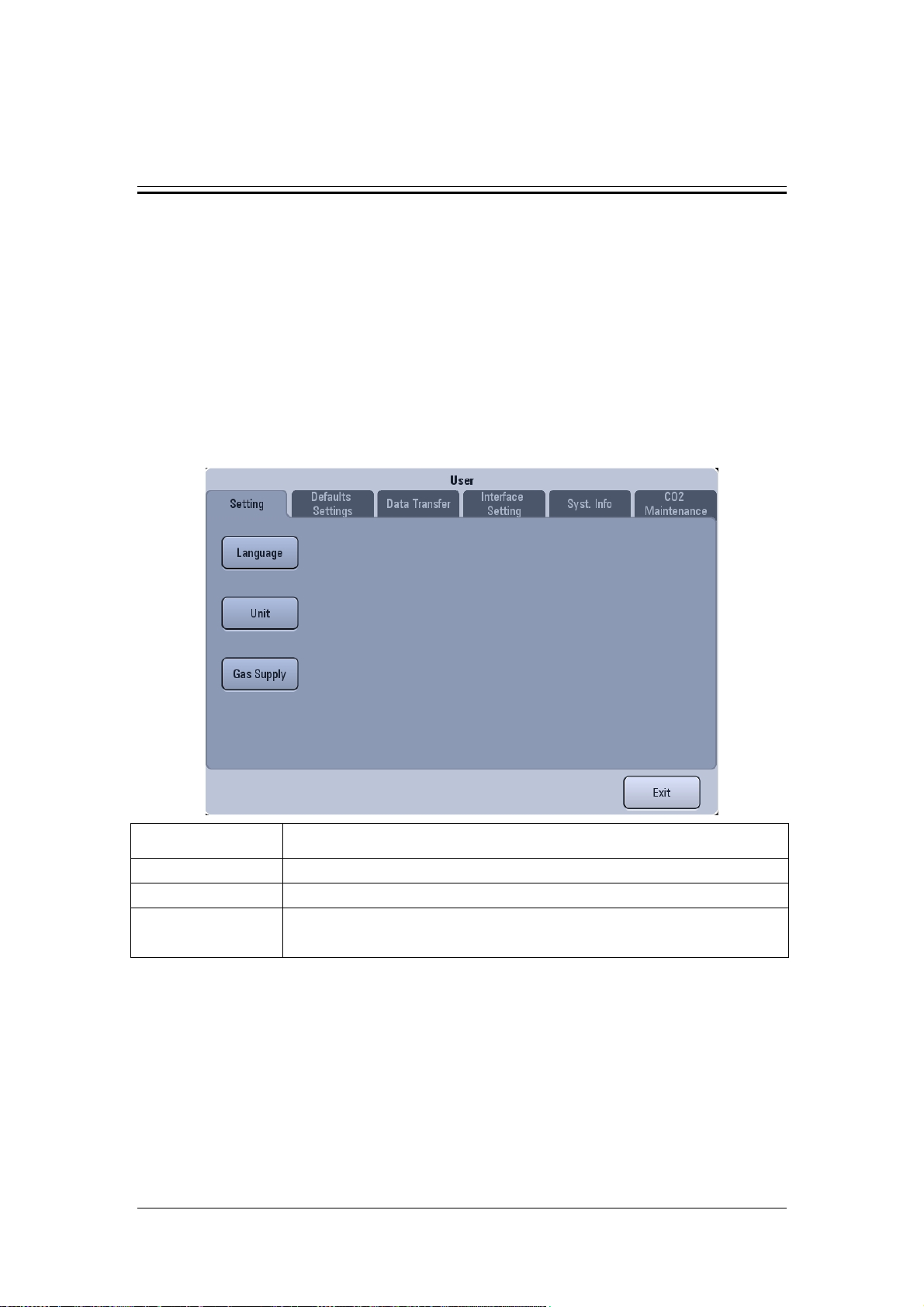
4 Maintenance Menu and Software Upgrade
4.1 User Maintenance
4.1.1 Overview
This section introduces the functions of user maintenance. User maintenance is mainly used
by the equipment maintenance personnel. It includes these functions: setup, defaults settings,
data transfer, interface setting, system information, and CO2 in maintenance.
4.1.2 Setting
Setting item Description
Language Set the screen display language.
Unit Set Paw unit, weight unit, and CO2 unit.
Gas supply Set O2 supply type. If the gas supply type is set incorrectly, use of partial
functions may be restricted (such as O2 enrichment etc.).
4-1
Page 82
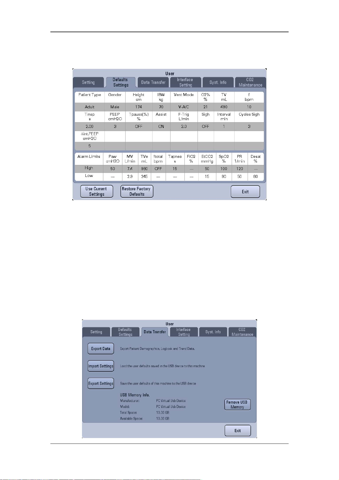
4.1.3 Defaults Settings
The ventilator settings can be adjusted as required. When [Use Current Settings] is selected,
the settings in Defaults Settings window will be replaced by the current settings. After the
ventilator is powered on and receives a new patient, it uploads the settings in Defaults
Settings window automatically.
When [Restore Factory Defaults] is selected, the settings in Defaults Settings window will
be restored to factory defaults. After the ventilator is powered on and receives a new patient,
it uploads the settings in Defaults Settings window automatically.
4.1.4 Data Transfer
When the department which the ventilator is used in needs to configure multiple ventilators,
the function of transferring settings is used to export or import the current settings and
defaults of the ventilator setting items. All USB memories have space of more than 10M
available and are in FAT32 or FAT format.
4-2
Page 83

4.1.4.1 Export Settings
1. Insert the USB memory into the USB connector of the ventilator.
2. Select [Setup]→[Maintain]→[User]→enter the required password→[Data Transfer].
3. Select [Export settings] to save the ventilator’s current settings and defaults to the USB
memory.
4.1.4.2 Import Settings
1. Insert the USB memory into the USB connector of the ventilator.
2. Select [Setup]→[Maintain]→[User]→enter the required password→[Data Transfer].
3. Select [Import settings] to load the settings in the USB memory to the ventilator.
4.1.4.3 Export Data
This function is used for data export, which means to export patient demographics, current
setting parameters, current alarm limits, and trend data of the ventilator in the format of
“blg”.
To export data,
1. Insert the USB memory into the USB connector of the ventilator.
2. Select [Setup]→[Maintain]→[User]→enter the required password→[Data Transfer]
→[Export Data]. The system checks the availability of USB memory. If the USB
memory is available and has sufficient space, the system exports patient demographics,
current setting parameters, current alarm limits, tabular trend, graphic trend, PEEPi
measured value, P0.1 measured value, Vtrap measured value, NIF measured value,
calibration data, and event log.
3. After data exporting is completed, select [Remove USB Memory] to remove the USB
memory.
4-3
Page 84
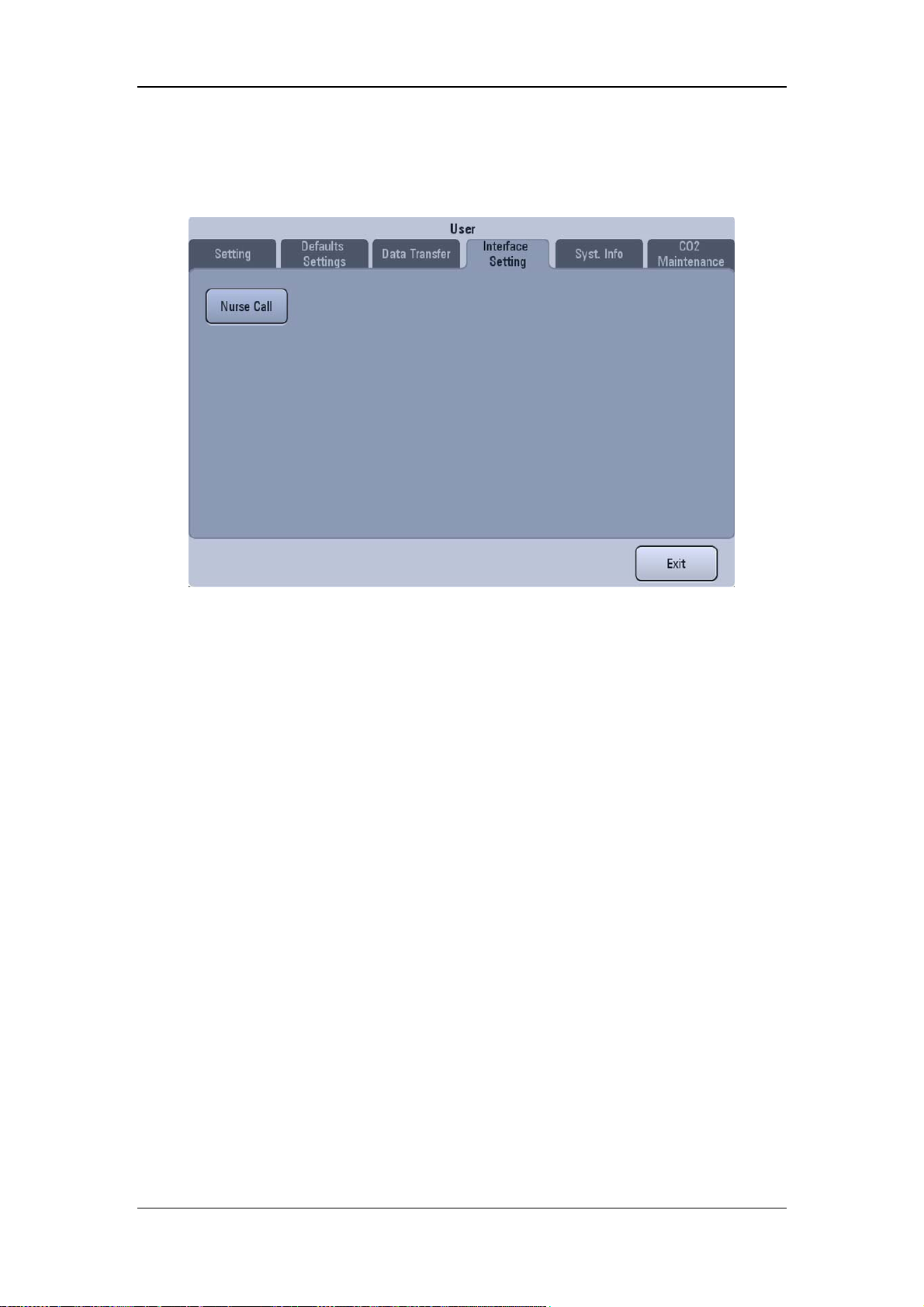
4.1.5 Interface Setting
Interface setting includes nurse call.
4.1.5.1 Nurse Call
The nurse call function means that the ventilator outputs nurse call signals to the nurse call
system when an alarm which meets the user set requirements occurs.
The nurse call function is activated only when:
1. The nurse call function is switched on;
2. An alarm which meets the user set requirements occurs;
3. The ventilator is not in Alarm AUDIO PAUSED status.
To set nurse call,
1. Select [Setup]→[Maintain]→[User]→enter the required password→[Interface
Setting]→[Nurse Call].
2. Select [Switch] and toggle between [ON] and [OFF].
[ON]: to switch on the nurse call function.
[OFF]: to switch off the nurse call function.
3. Select [Signal Type] and toggle between [Pulse] and [Continuous].
[Pulse]: indicates that the nurse call signals outputted are pulse signals lasting for one
second. When multiple alarms occur simultaneously, only one pulse signal is outputted.
If a new alarm occurs while the ongoing alarm is not cleared yet, a new pulse signal will
be outputted.
[Continuous]: indicates that the nurse call signal lasts until the alarm ends, i.e. the
duration of a nurse call signal equals to that of the alarm.
4-4
Page 85
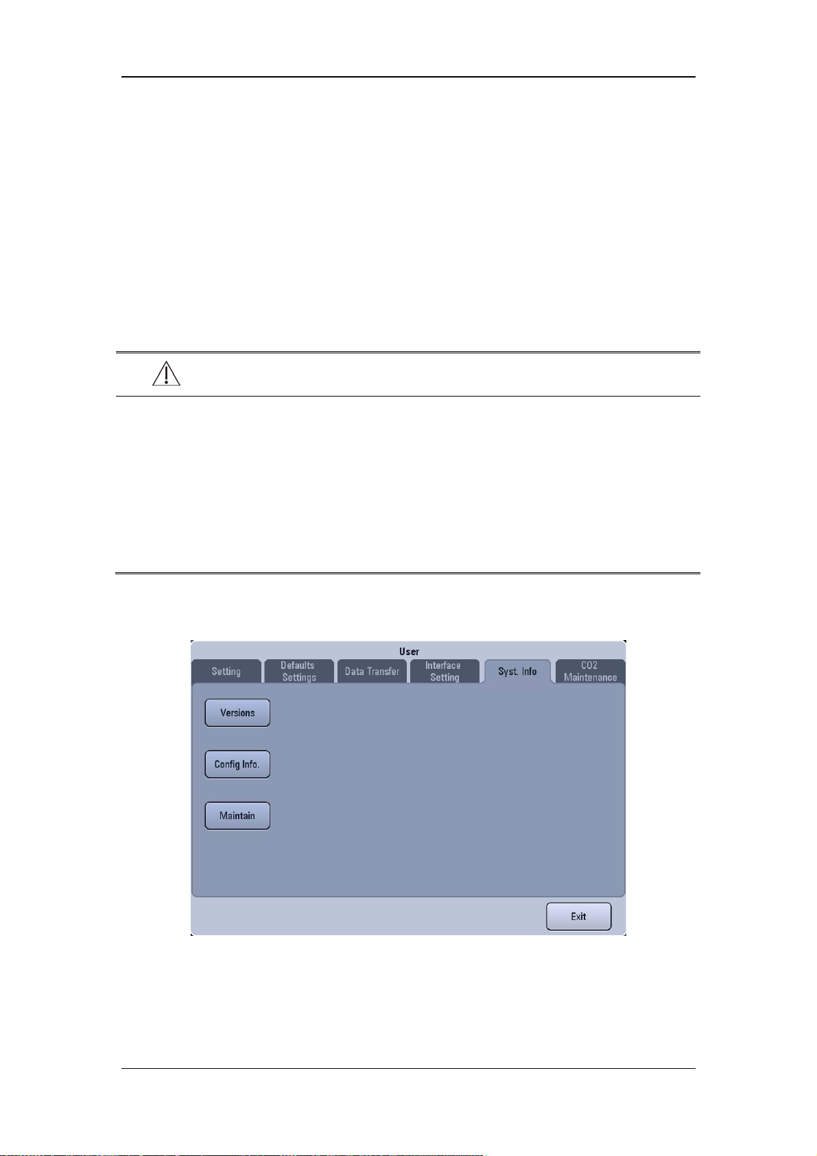
4. Select [Contact Type] and toggle between [Normally Open] and [Normally Closed].
[Normally Open]: normally open signals are used to trigger the nurse call function.
[Normally Closed]: normally closed signals are used to trigger the nurse call function.
5. Select [Alarm Level] and set the alarm level for nurse call signals triggered alarm.
6. Select [Alarm Type] and select the alarm type to which nurse call signals triggered
alarm belongs.
If no setting is made for [Alarm Level] or [Alarm Type], nurse call signals will not be
triggered whatever alarm occurs
WARNING
Do not rely exclusively on the nurse call system for alarm notification. Remember that
the most reliable alarm notification combines audible and visual alarm indications with
the patient’s clinical condition.
Use the specified nurse call cable when connecting with the hospital’s nurse call system
through the nurse call connection port. Failure to do so may burn the machine and
produce electric shock hazard.
Inspect the ventilator alarm signals periodically when using the nurse call function.
4.1.6 System Information
4-5
Page 86
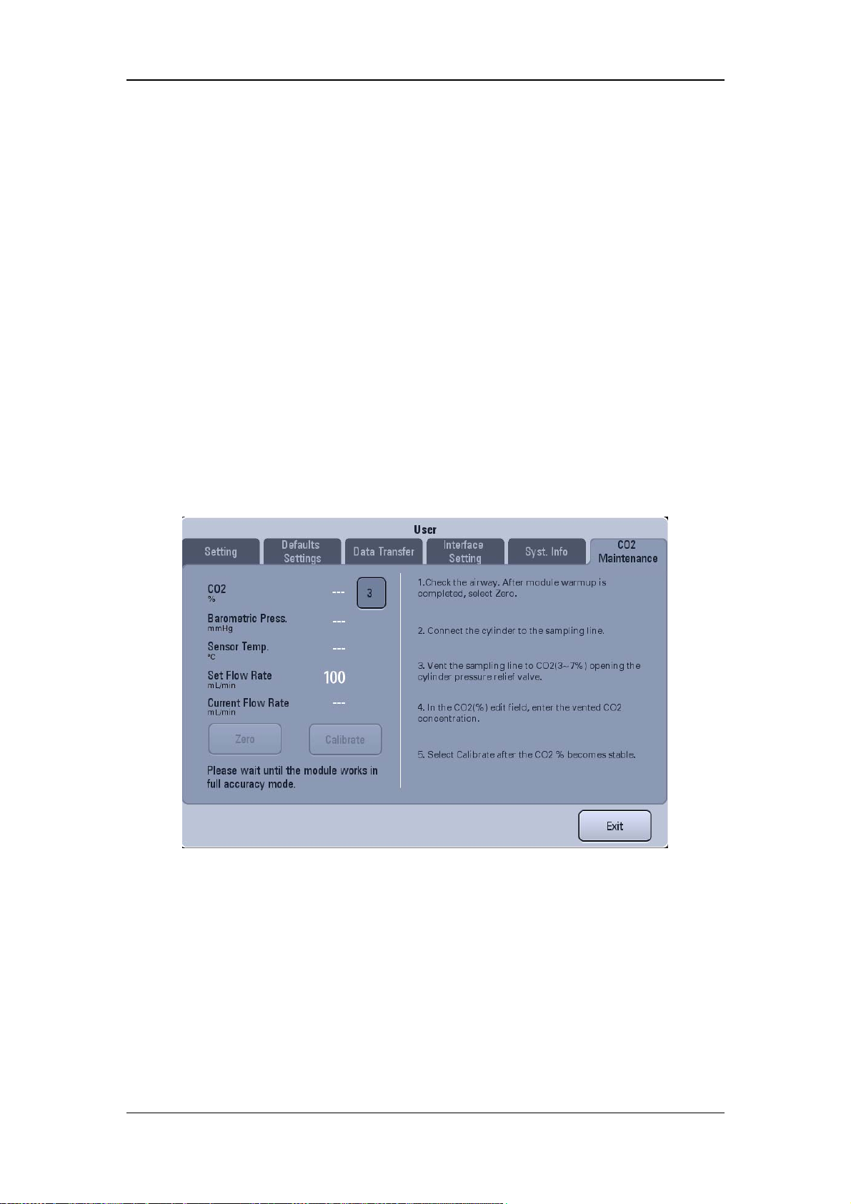
4.1.6.1 Version Information
The version information of the system software can be queries.
4.1.6.2 Configuration Information
The configuration information of the ventilator such as ventilation mode and special function
can be queries.
4.1.6.3 Maintenance Information
The system total running time, system startup time, CO2 last calibration time, O2 sensor last
calibration time, flow sensor last calibration time, time left for next blower maintenance and
time of last maintenance can be queried.
4.1.7 CO2 Maintenance
This setting item is available when the sidestream CO2 module is configured. For CO2
zeroing and CO2 calibration, refer to 5.3.5 Mainstream CO2 Zeroing (User) and 5.3.6
Sidestream CO2 Zeroing (User).
4-6
Page 87
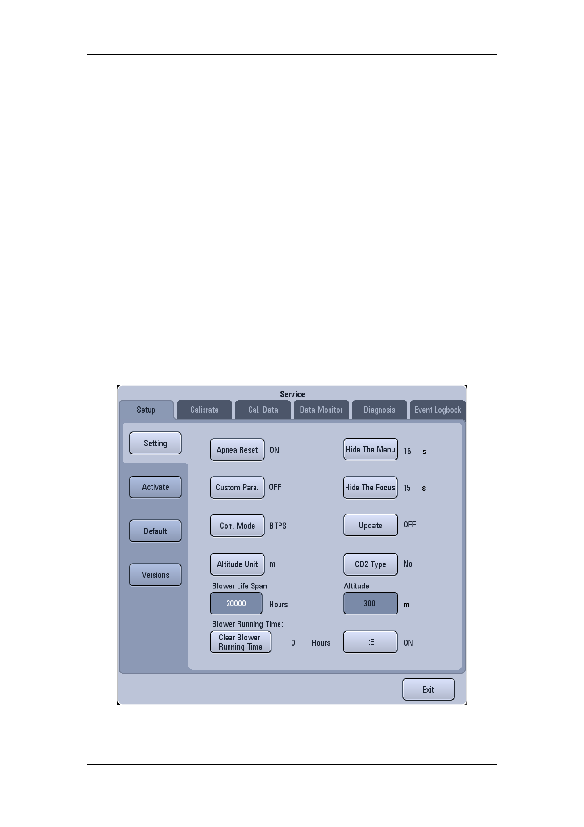
4.2 Factory Maintenance
4.2.1 Overview
Factory maintenance is used in such scenario as factory functional configuration, equipment
calibration, troubleshooting. The factory maintenance menu includes the following functions:
factory setup, factory calibration, calibration data, data monitoring, diagnosis test, event
logbook.
The factory maintenance password can be obtained in the preface chapter of this manual.
Warning: this menu can be operated only by Mindray authorized service engineers. Operating
the menu by unauthorized engineer may cause the machine unable to work normally.
4.2.2 Factory Setup
4.2.2.1 Overview
Factory setup includes: setup, functional activation, restore factory defaults, and versions.
4-7
Page 88

4.2.2.2 Setup
The following table lists the setting items and their descriptions.
Setting item Description
Update
Correction Mode Can be set to ATPD and BTPS.
Apnea Reset Can be set to ON and OFF.
Hide The Focus
Hide The Menu
Custom Parameter
Altitude
Altitude Unit Set altitude unit, including two options: m and ft.
CO2 Type
Blower Life Span Set blower life span.
Clear Blower Running
Time
I:E
Can be set to ON and OFF, to switch on or off the USB memory
update function.
Can be set to OFF, 15s, 30s, and 60s. When it is set to OFF, the
focus will not hide automatically. When it is set to other options, if
no operation is performed for corresponding period of time, the
focus will disappear automatically.
Can be set to OFF, 15s, 30s, and 60s. When it is set to OFF, the
menu will not hide automatically. When it is set to other options, if
no operation is performed for corresponding period of time, the
menu will disappear automatically.
Include two options: ON and OFF. When the factory locates a
failure, Custom Parameter can be switched on to view the trend of
corresponding parameter monitored value. After use, the option
needs to be set to OFF.
Set altitude. When the atmospheric pressure sensor is faulty, the
atmospheric pressure can be calculated based on altitude.
Set whether CO2 module is integrated based on the actual
configuration of the machine. If CO2 module is integrated, the type
of CO2 module needs to be set consistent with the actual one. Three
options are included: Mainstream, Sidestream, and No.
Click this button after replacing the blower to clear the blower
running time. Running time information is displayed next to the
button.
Can be set to ON and OFF. When it is set to ON, the system
displays the monitoring values of Tinsp and I:E. When it is set to
OFF, the system cannot display the monitoring values of the Tinsp
and I:E.
4.2.2.3 Functional Activation
In the Activate menu, payment configuration can be activated via activation code or USB
memory to use the corresponding function on trial. For details, refer to 4.3.3Function
Activation.
4-8
Page 89
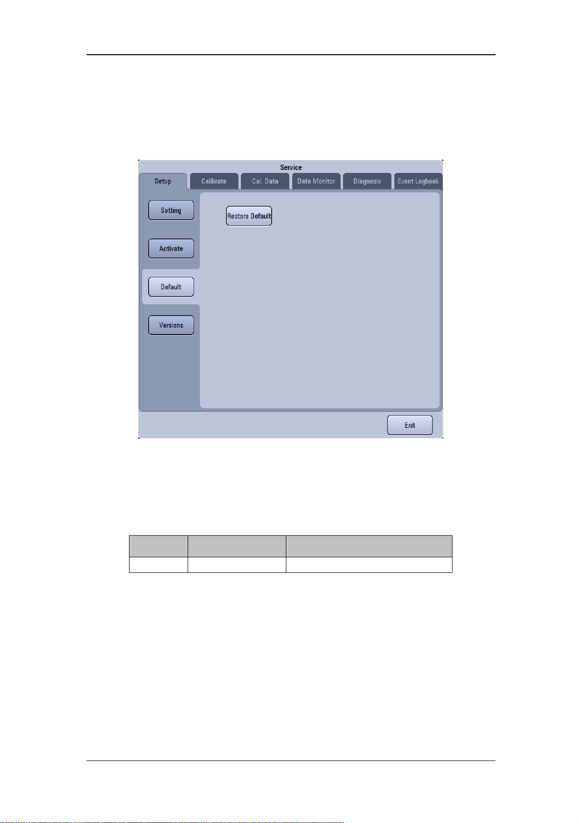
4.2.2.4 Restore Factory Defaults
Restoring factory defaults means to restore the values of setting items to factory default
values. The default values saved in the new patient default setting property page are also
restored to factory default values.
Restoring factory defaults will clear user log and saved spirometry loops (including reference
loop and P-V loop). Factory log will not be cleared.
The setting items which are not affected by restoring factory defaults include: inherent setting
items, power-on initialization items, menu entry initialization items, date and time setting
items, language and factory settings.
Language settings include:
Module Position Setting item
User Setting Language
4-9
Page 90
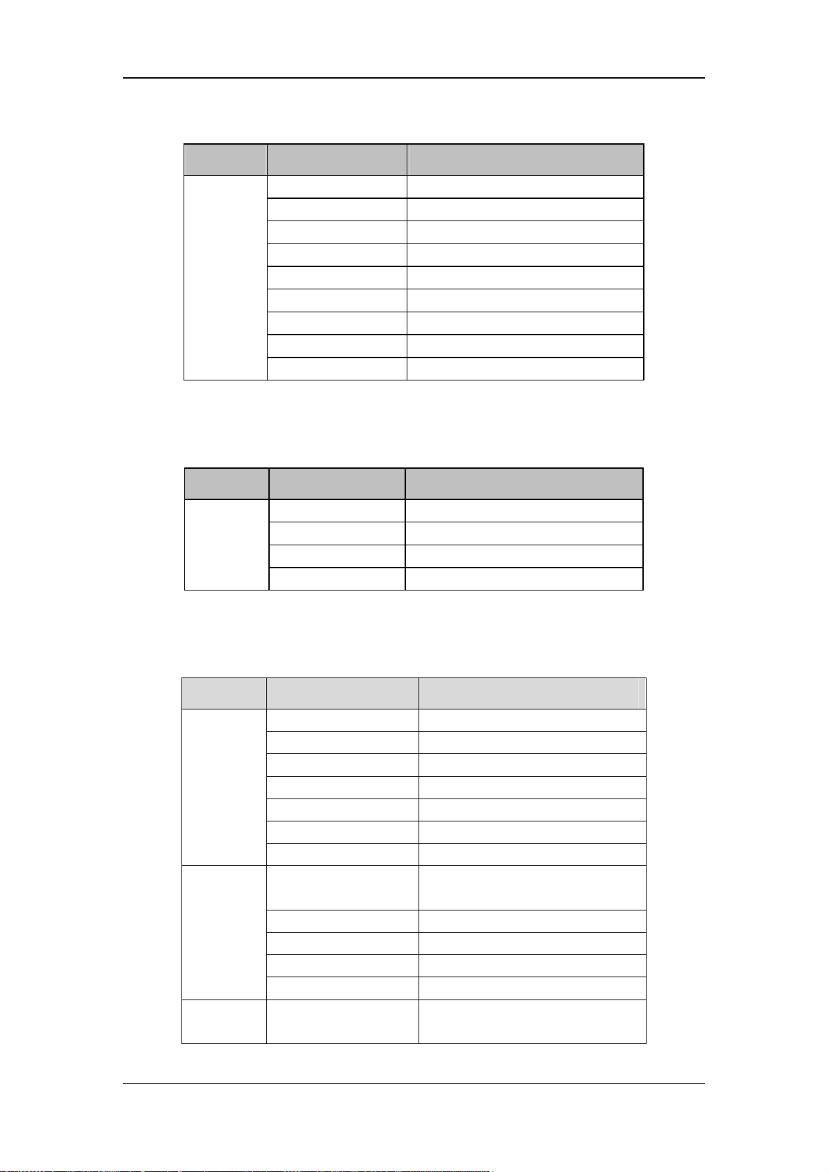
Factory settings include:
Module Position Setting item
Service Setup Correction Mode
Setup Blower Life Span
Setup Update
Setup Altitude Unit
Setup Altitude
Setup Custom Parameter
Setup Apnea Reset
Setup Hide the Focus
Setup Hide the Menu
Inherent setting items: the values of setting items are not affected by transferring settings or
restoring factory defaults.
Module Position Inherent setting item
Service Setup CO2 Type
Setup Blower Life Span
Activate Preset item in ticked state on trial
Activate Not activate preset item in ticked state
Power-on initialization items: restore to factory defaults each time after power-on; reserve the
latest preset item values each time after accessing the menu when not powered off.
Module Position Power-on initialization item
Nebulizer Nebulizer Time
P-V Tools Pstart
P-V Tools Pmax
Procedure
Service
Screen
Layout
P-V Tools Flow
P-V Tools Vlimit
P-V Tools History Loop
P-V Tools Reference Loop
Calibration-Pressure
Calibration
Calibration-Exp. Valve Calibration Reference
Setup Correction Mode
Setup Update
Setup Custom Parameter
Screen Layout Waveforms
Calibration Device
4-10
Page 91
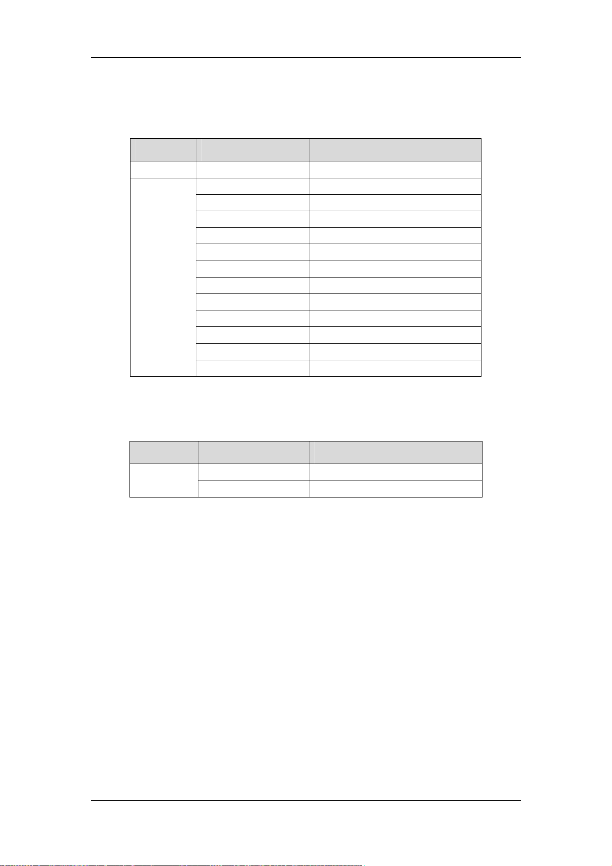
Menu entry initialization items: restore to factory defaults each time after accessing the
menu.
Module Position Menu entry initialization item
User CO2 Calibration CO2 Calibration Concentration
Data Monitor Parts
Diagnosis Blower speed
Diagnosis Pressure
Diagnosis Insp. valve
Diagnosis Insp. valve
Service
Date and time setting items: neither being initialized nor being kept unchanged; displayed
following the ascending rules for time and date.
Diagnosis O2 Insp. valve
Diagnosis O2 Insp. valve
Diagnosis Exp. valve
Diagnosis Exp. valve
Diagnosis Nebulizer valve
Diagnosis Safety valve
Diagnosis Activation code/USB
Module Position Date and time setting items
Time setting
Time and date Date
Time and date Time
4-11
Page 92
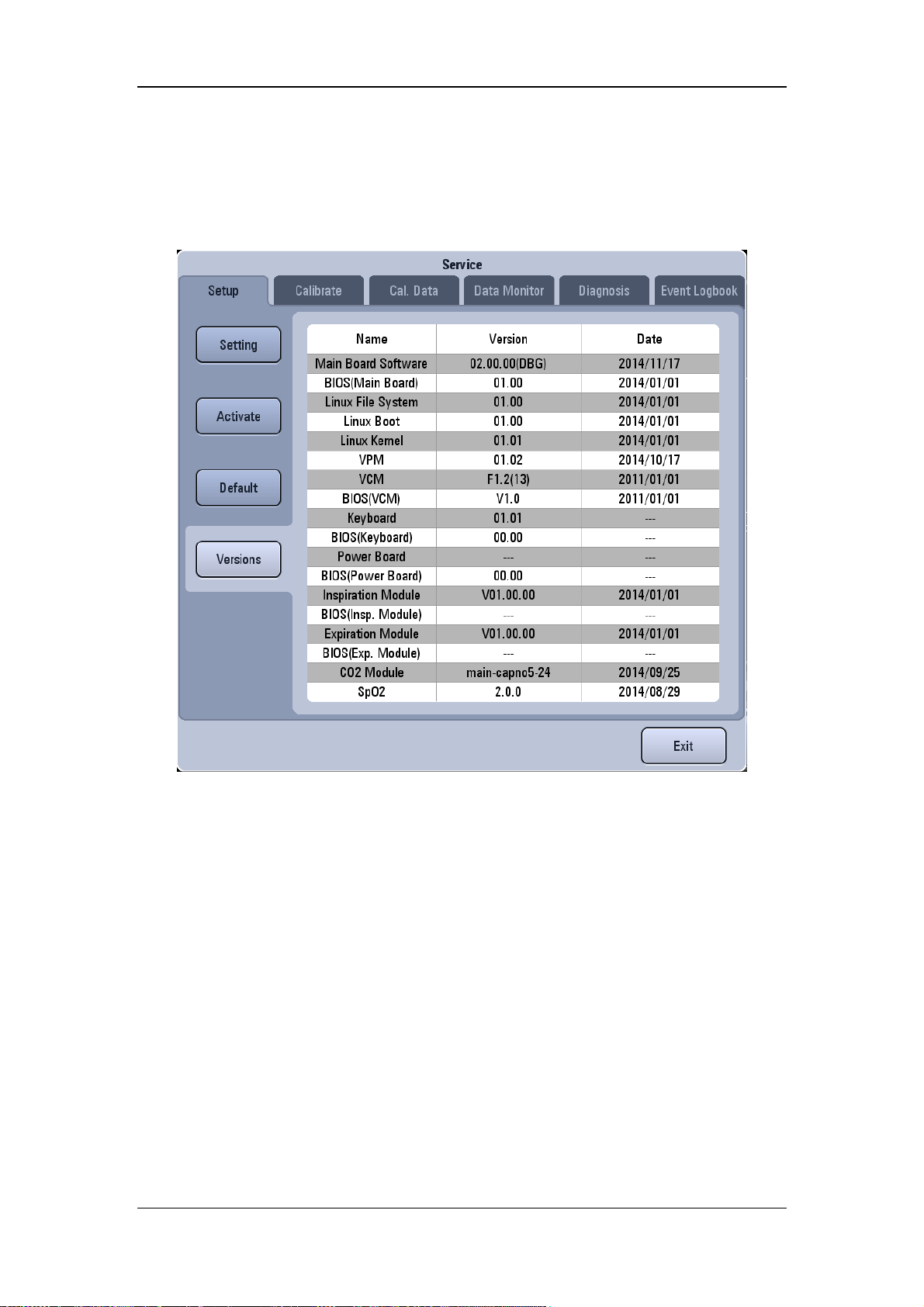
4.2.2.5 Version Information
In [Ver si o ns ] menu, you can view the version information of the software currently used by
each module.
4-12
Page 93
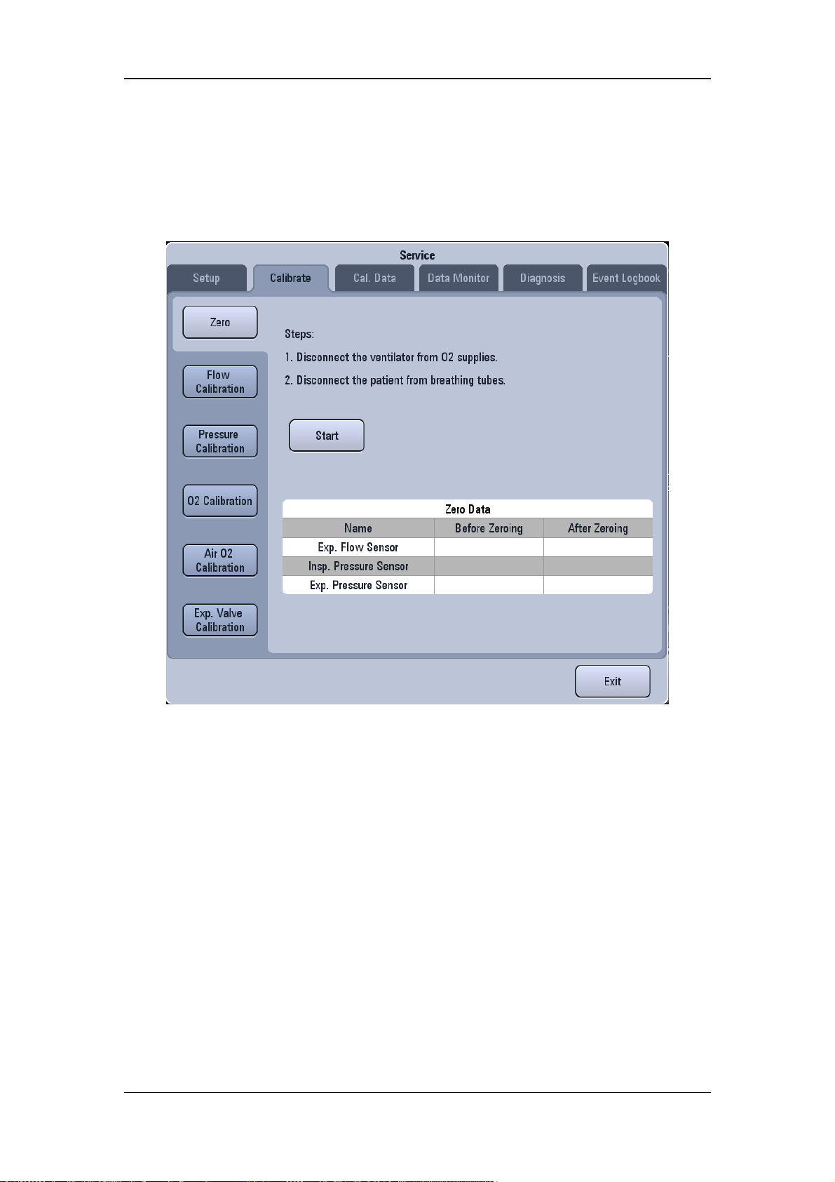
4.2.3 Factory Calibration
The factory calibration menu provides access to the following: zeroing, flow calibration,
pressure calibration, Exp. valve calibration, O2 calibration, and Air-O2 calibration.
For details, refer to 5.3 System Calibration.
4-13
Page 94
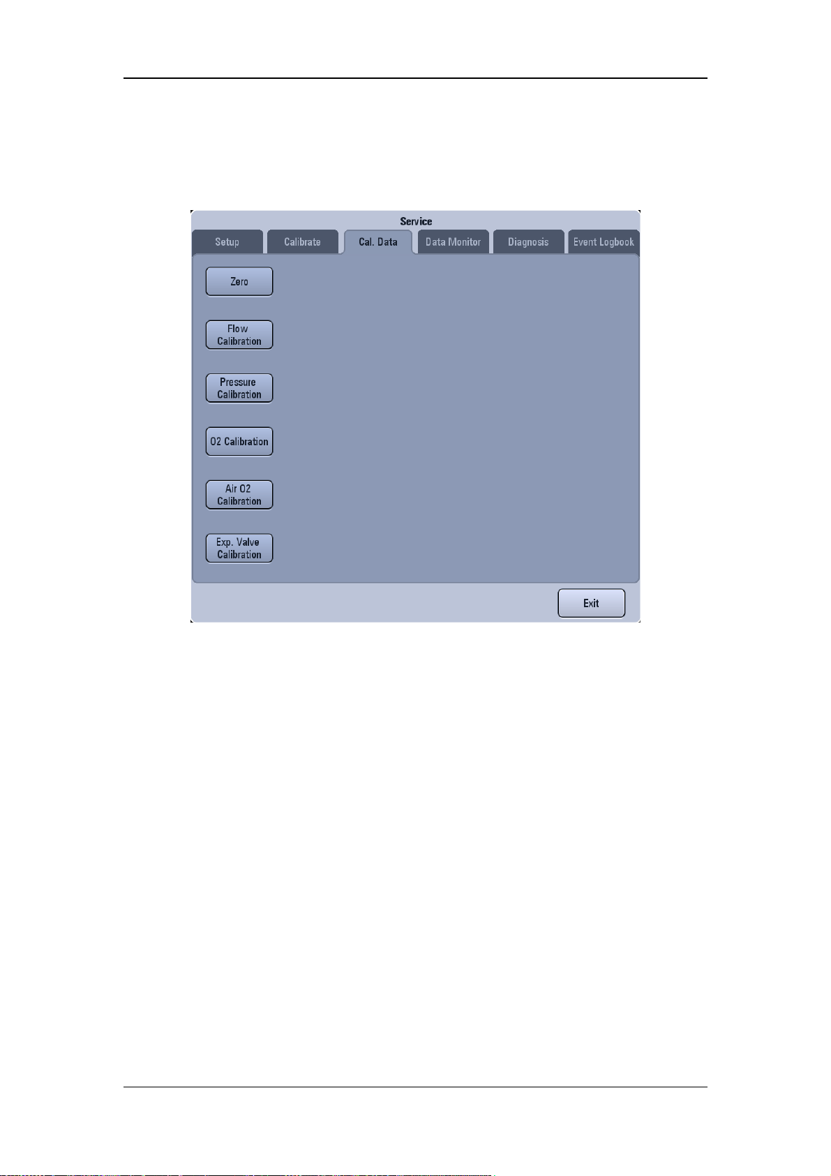
4.2.4 Calibration Data
The calibration data menu provides the following functions: zero point data monitoring, user
calibration table and factory calibration table of all parts, and Air-O2 calibration data display.
4-14
Page 95
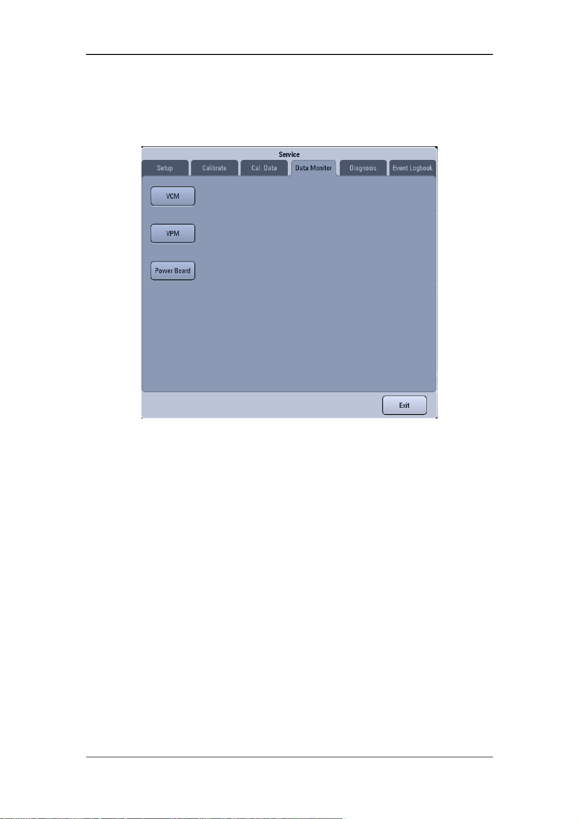
4.2.5 Data Monitoring
The data monitor menu provides the following functions: VCM data monitoring, VPM data
monitoring, and power board data monitoring.
4-15
Page 96
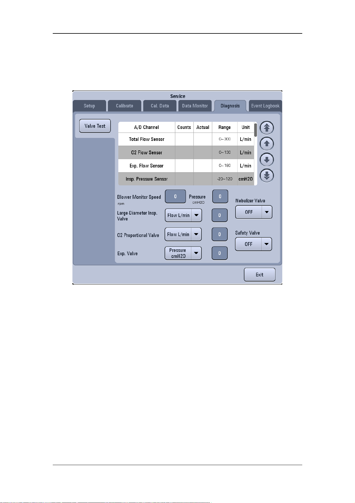
4.2.6 Diagnosis Test
Diagnosis test provides valve test device. For details, refer to 6.6Diagnostic Test.
4-16
Page 97
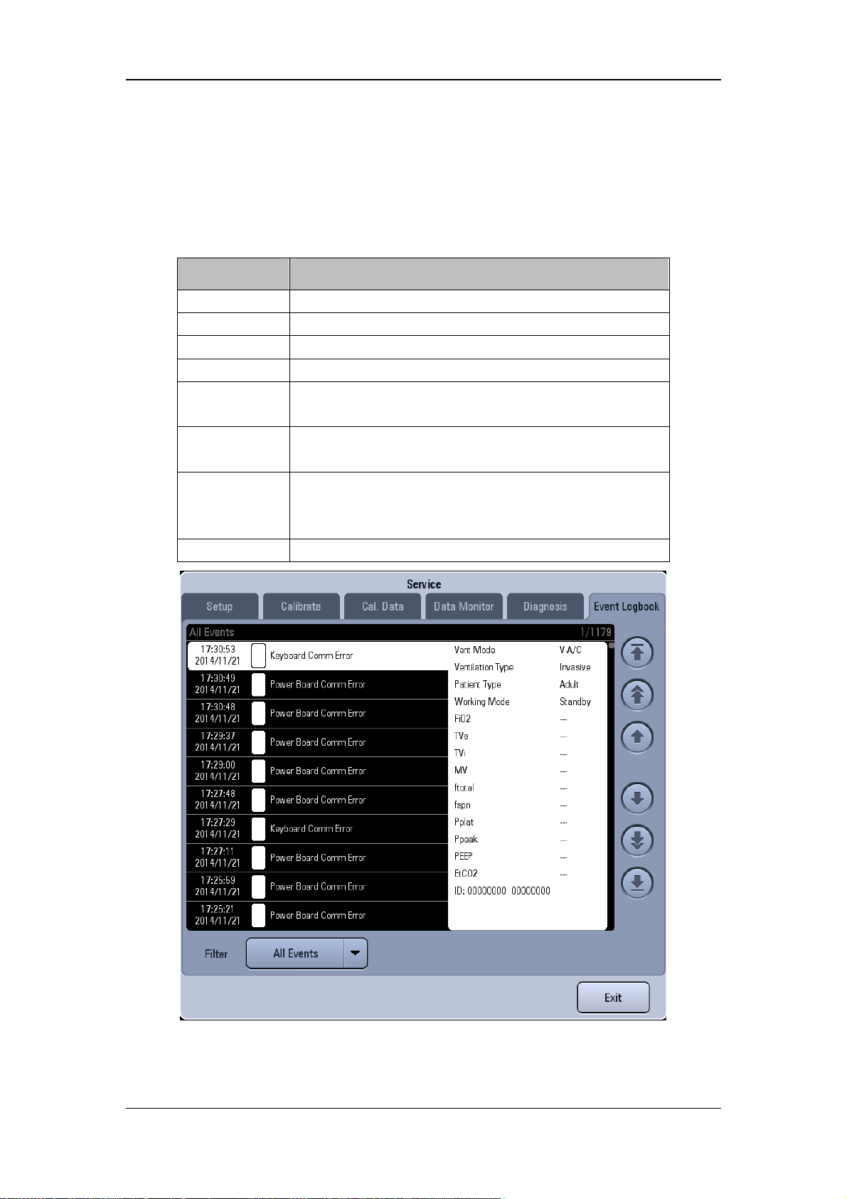
4.2.7 Event Logbook
Event logbook can be viewed, including alarm logbook, operation logbook, error logbook,
maintenance information. You can select to view event logbook via filter, which is
configurable.
Setting item Functional description
High Alarms Display all high alarm events only.
Med Alarms Display all medium alarm events only.
Low Alarms Display all low alarm events only.
All Alarms Display all alarm events only.
Operation
Information
Error
Information
Maintenance
Information
All Events Display all events.
Display all operation events only.
Display all error events only (only available in factory event
logbook and not available in user event logbook).
Include maintenance operation such as zeroing and
calibration, and selftest operation (only available in factory
event logbook and not available in user event logbook).
4-17
Page 98

4.3 Software Upgrade and Software Function
Activation
CAUTION
Software upgrade and configuration activation can be performed by Mindray
authorzied professional service personnel only.
You can perform software upgrade on the ventilator by downloading the upgrade software
through network or by using USB memory. You can also upgrade software supported optional
configuration through the activation code. Before activating the optional configuration, the
optional configuration can be applied for a maximum of 30 days on trial.
4.3.1 Network Upgrade
You can upgrade the following programs on the ventilator by downloading the upgrade
software through network:
BIOS (main board) software
Main board software
Multi-language library
Icon library
Start-up screen
Audio file
General configuration (requires password )
System functional configuration
Linux file system
Linux kernel
Protection module software
Control module software
Keyboard software
Power board software
Insp. module software
Exp. module software
M02C module software
SpO2 module software
4-18
Page 99

CAUTION
Before software upgrade, disconnect the ventilator from the patient and back up the
important data.
NOTE
Make sure that the version of the upgrade package is the desired one. To obtain the
latest upgrade package, please contact us.
Before upgrading the system software, check the version information of the booting
software. If it is not the latest, upgrade the booting software to the latest version first
and make sure of software compatibility.
You can select the following operations to upgrade the corresponding software based on your
requirement. You must perform 4.3.1.1Network Connection before upgrading any software.
4.3.1.1 Network Connection
4.3.1.2 Network Connection
NOTE
Before upgrading any software, make sure that the network cable, Hub, and notebook
computer are connected correctly and reliably.
The recommended length of the network cable is not greater than 1 m.
4-19
Page 100
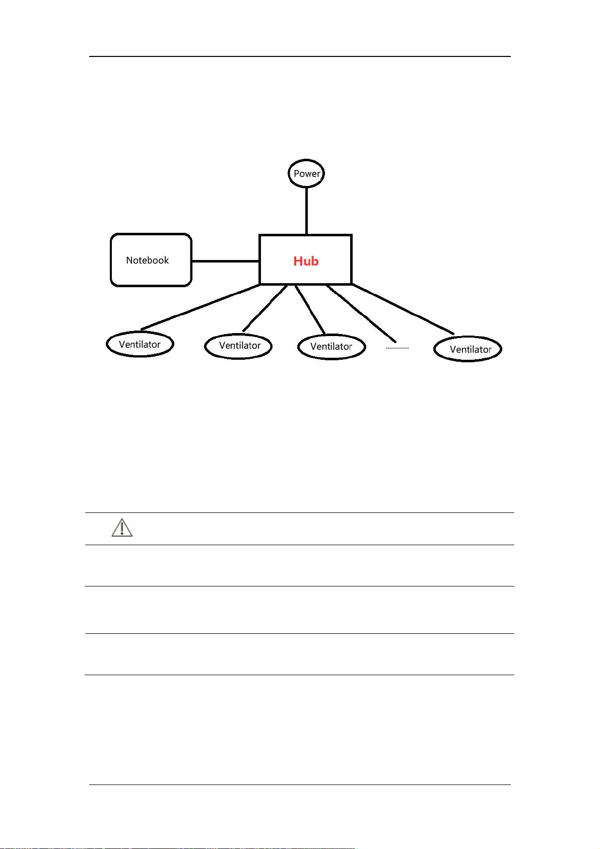
Perform network connection as follows before software upgrade:
Connect the ventilator, Hub and notebook computer by using the straight through cable.
Connect the Hub to the power source and make sure that the network is connected.
2. Set the IP address of the notebook computer. Make sure that the IP address of the
notebook computer is in the same IP segment with the ventilator and they do not repeat.
The IP address of the ventilator is fixed to the setting when delivered from the factory,
which is “192.168.23.250”. The IP address of the notebook is generally set to
“192.168.23.23”.
4.3.1.3 Booting Software Network Upgrade
CAUTION
Switching off or powering off the equipment during booting software upgrade can
cause system down.
NOTE
When selecting the upgrade package, make sure that the checksum and software
version are same to that provided by the factory.
4-20
 Loading...