

Page 1

Pulse Oximeter
Operation Manual
Page 2

Page 3

Preface
For this manual, the issued Date is October 2005 (Version: 1.5).
Safety Symbols
Warning
A Warning indicates that failure to follo w proper instructions can cause
death or injury to the patient, the operator, or serious damage to the
equipment.
Caution
A Caution indicates that fail ure to foll ow proper i nstructions may caus e
serious injury to the patient, the operator, or may cause damage to the
equipment.
Note
A Note is an indication of supplemental information to the operation, or
handling, of the equipment, or associated accessories.
This symbol indicates type BF applied part according to IEC 60601-1.
This symbol indicates the dual-purpose socket can connect with the PC
communication cable.
Page 4

Illustrations
All illustrations in this manual are provided as examples only . They may
not necessarily reflect your setup or data displayed on your Pulse
Oximeter.
Page 5

Contents
Chapter 1 Safety Information...........................................................1
Chapter 2 General ........................................................................... 5
2.1 Introduction.............................................................................5
2.2 Functions ................................................................................ 5
2.3 Appearance............................................................................. 6
2.4 Displayed Information ............................................................. 7
2.5 Button Operation..................................................................... 8
2.5.1 Power Button ................................................................ 8
2.5.2 Backlight Button............................................................ 8
2.5.3 Confirm ID Button ......................................................... 9
2.5.4 Delete ID Button............................................................ 9
Chapter 3 Installation......................................................................11
3.1 Unpacking and Inspection......................................................11
3.2 Install Batteries.......................................................................11
3.3 Power-on............................................................................... 13
3.4 Connect SpO2 Sensor ........................................................... 13
3.5 Connect Computer................................................................ 14
Chapter 4 Measurement ................................................................ 15
4.1 Measuring Principle............................................................... 15
4.2 Precautions...........................................................................16
4.3 Measuring Steps...................................................................18
4.3.1 Adult Measurement ..................................................... 18
4.3.2 Neonatal Measurement............................................... 19
4.3.3 Placing Neonatal SpO2 Sensor.................................... 19
4.4 Measuring Restrictions.......................................................... 21
Chapter 5 Other Functions............................................................. 23
5.1 Data Management................................................................. 23
I
Page 6

Contents
5.1.1 Data Storage............................................................... 23
5.1.2 Data Adding................................................................24
5.1.3 Data Protection........................................................... 25
5.1.4 Data Deletion..............................................................25
5.2 Messages Prompting ............................................................ 26
5.3 Power Management.............................................................. 28
Chapter 6 Maintenance.................................................................. 29
6.1 System Check....................................................................... 29
6.2 General Cleaning..................................................................30
6.3 Sterilization/Disinfection........................................................ 32
6.4 Disposal................................................................................32
Chapter 7 Pulse Oximeter Management System...........................33
7.1 Installation and Uninstall ....................................................... 33
7.1.1 Installation................................................................... 33
7.1.2 Uninstall......................................................................34
7.2 Main Interface ....................................................................... 35
7.2.1 Menu Bar .................................................................... 35
7.2.2 Tool Bar....................................................................... 38
7.2.3 Data Area.................................................................... 38
7.3 Functions .............................................................................. 39
7.3.1 Data Output................................................................. 39
7.3.2 Software Upgrade.......................................................41
7.3.3 File Management........................................................ 44
7.3.4 Modify Patient Information .......................................... 45
7.3.5 Print Data.................................................................... 46
7.3.6 Prompt Message......................................................... 47
Chapter 8 Accessories................................................................... 49
Appendix A Specifications.................................................................. 50
II
Page 7

Chapter 1 Safety Information
This chapter contains important safety information related to general
use of the Pulse Oximeter. Other important safety information appears
throughout the manual in sections that relate specifically to the
precautionary information.
Note
Important! Before use, carefully read this manual, all safety
information and specifications.
This device is not intended for home use.
Federal Law (USA) restricts this device to sale by or on the order of
a physician.
The Pulse Oximeter complies with Class-A requirements of the
EN55011 standard.
Warning
This device is not intended as a device used for treatment
purposes.
It is important for the hospital or organization that uses this
equipment to carry out a reasonable maintenance schedule.
Failure to do so may result in equipment failure, or injury to the
patient or operators.
The Pulse Oximeter is intended only as an adjunct in patient
assessment. It must be used in conjunction with clinical signs and
symptoms.
1
Page 8

Safety Information
Warning
The Pulse Oximeter is to be operated onl y by medical doctors or
trained healthcare personnel to measure the SpO2 of clinical
patients (including adult, pediatric and neonatal patients) in
hospitals and healthcare agencies or in the process of transporting
patients.
The Pulse Oximeter is designed for real-time and rapid
measurement of the patient’s SpO2. It is not suitable for long-time
continuous patient monitoring. Continual measurement must not
exceed 2 hours.
Before using the Pulse Oximeter, the user should check and make
sure the device and its accessories can work properly and safely.
When using the Pulse Oximeter together with the electrical surgery
equipment, the user should pay attention to and guarantee safety
of the patient being measured.
To avoid fire or explosion hazards, do not use the Pulse Oximeter
at places where such flammable material as anesthesia gas is
present.
Do not pull or lift the Pulse Oximeter by its connection cable. T hat
may lead to device falling and consequent patient injuries.
It is not recommended to hang the Pulse Oximeter when
transporting patients. Safety hazards may arise from the large
amplitude swing during the transportation.
Do not use the Pulse Oximeter or its sensor around working MRI
equipment. Induction current may lead to damages. The device
may affect operation of MRI equipment and vice versa.
The Pulse Oximeter and its accessories may be contaminated by
microorganism during transporting, use and storage. Use the
2
Page 9

Safety Information
recommended methods to sterilize and disinfect the Pulse
Oximeter or its accessories when the packing material is damaged,
or it has not been used for a long time.
Caution
The Pulse Oximeter should be appropriatel y placed. Keep it from
falling, strong vibration or other mechanical damage.
The Pulse Oximeter is a commonly sealed device. The user should
keep its surface dry and clean, and prevent any liquid from
infiltrating it.
Don’t use mobile phones around when the Pulse Oximeter is in
operation.
The Pulse Oximeter should only be maintained by personnel
approved by our company.
Before use the Pulse Oximeter on patients, the user should be
familiar with its operation.
3
Page 10

FOR YOUR NOTES
Safety Information
4
Page 11

Chapter 2 General
2.1 Introduction
The Pulse Oximeter is a portable measuring device powered by
common or rechargeable batteries. It is compact, light, flexible to use
and easy to learn.
Parameters measured by the Pulse Oximeter include: arterial oxygen
saturation (SpO
Oximeter measures these parameters through a SpO
displays them on the LCD screen after certain further processing.
The Pulse Oximeter is operated and controlled by three buttons, which
are Power button, Backlight button and Confirm ID button. The Pulse
Oximeter is also capable of managing measured data and transmitting
the patient’s trend through the dual-purpose socket to a PC for printing.
), pulse rate (PR) and pulse strength. The Pulse
2
sensor and
2
2.2 Functions
The Pulse Oximeter has the following functions:
Measuring: SpO
Prompting: Memory full, ID full, low battery, standby, and
technical error etc.
Power managing: automatic standby, automatic shutdown;
Data Managing: data storage, data protection, data deletion;
Data Printing: patient information and trend data;
For the data printing function, you must install the Pulse Oximeter
management system in a PC equipped with a printer, and connect the
Pulse Oximeter with the PC by a communication cable.
, PR and pulse strength;
2
5
Page 12
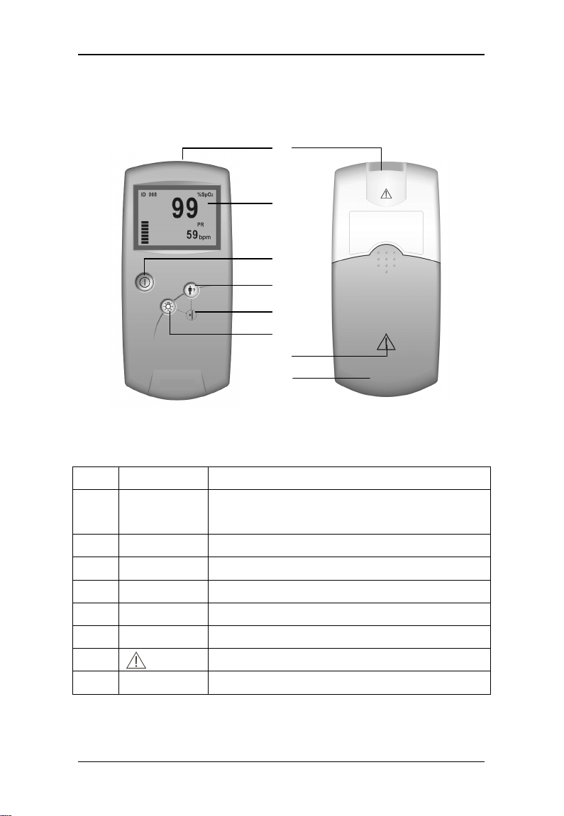
2.3 Appearance
General
①
②
③
④
⑤
⑥
⑦
⑧
Figure 2-1 Front Panel Figure 2-2 Back Panel
Table 2-1 Appearance description
No. Description Remarks
Dual-purpose
①
socket
LCD It displays information listed in Table 2-2.
②
Power It turns on or off the device.
③
Confirm ID It confirms the patient ID for current measurement.
④
Delete ID
⑤
Backlight It turns on or off the backlight.
⑥
⑦
⑧
Battery door Open it to install or remove batteries.
It connects SpO2 sensor or PC communication cable.
A key combination of ④ and ⑥.
Caution. Refer to this manual.
6
Page 13
General
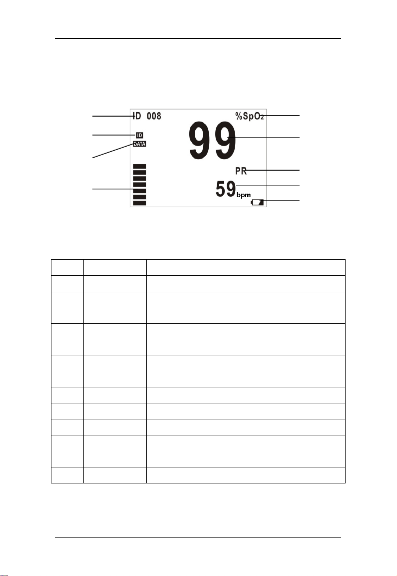
2.4 Displayed Information
Figure 2-3 shows information displayed on the LCD screen.
①
②
⑤
⑥
③
⑦
④
Figure 2-3 Displayed Information
Table 2-2 Description of displayed information
No. Description Remarks
ID number It displays current ID number ranging from 000 to 100
①
ID Full
②
Memory Full It appears when previous data is to be covered by
③
Pulse Strength It can display 7 segments at most to indicate real time
④
It displays “%SpO2”.
%SpO
⑤
⑥
⑦
⑧
⑨
2
value It displays SpO2 value and is refreshed every second.
SpO
2
PR It displays “PR”.
PR value It displays PR value and is refreshed every second.
Low battery It appears only when the battery energy is low.
It appears when ID≥95 and blinks when stored ID is
being covered by new ID.
new data. Please refer to 5.1.1 Data Storage.
pulse strength.
Unit: bpm (beats per minute)
⑧
⑨
Please refer to Chapter 3 Installation for displayed information of
startup and standby modes.
7
Page 14

General
2.5 Button Operation
Three soft buttons are available on the front panel.
Power Backlight Confirm ID
Figure 2-4 Buttons
2.5.1 Power Button
Power-on: Press to turn on the device.
Power-off: Press and hold for two seconds to turn off the device.
Note
The Pulse Oximeter is powered by batteries only. Please install
batteries before use according to the descriptions in 3.2 Install
Batteries.
In case the SpO2 cable becomes disconnected or the finger moves
away from the sensor, the Pulse Oximeter will automatically enter
the standby mode. Under this mode, when a finger is inserted into
the sensor, the Pulse Oximeter will automatically resume the
operation mode. Otherwise, if no finger is inserted in 5 minutes, the
Pulse Oximeter will be automatically shut down.
2.5.2 Backlight Button
Backlight on: Press the Backlight button to turn on backlight.
Backlight off: Press the Backlight button to turn off backlight.
8
Page 15

General
2.5.3 Confirm ID Button
The Confirm ID button is used to add data. It enables the user to add
data, without using a new ID number, to a re-test for the same patient
after the sensor is accidentally disconnected.
Refer to section 5.1 Data Management for detailed use of this button.
2.5.4 Delete ID Button
The Delete ID button is a key combination of the Backlight button and
the Confirm ID button.
Refer to section 5.1 Data Management for detail use of this button.
9
Page 16

FOR YOUR NOTES
General
10
Page 17

Chapter 3 Installation
3.1 Unpacking and Inspection
Please carefully remove the Pulse Oximeter and its accessories from
the package and check items by comparing them to the packing list.
Check the device for any mechanical damages.
Check all cables and accessories for damage.
In case of any problem, please contact our Customer Service.
Note
Please save all packaging materials for future transportation or
storage use.
Warning
The user should keep the packing materials at places out of
children’s reach. Before disposing the packing materials, check
with your local waste officials for details in your area for recycling
options or proper disposal.
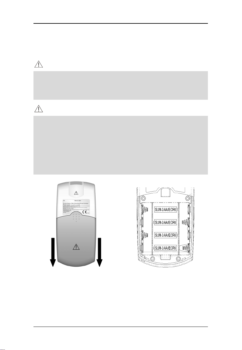
3.2 Install Batteries
The Pulse Oximeter is powered by four batteries. Follow the steps
below to install batteries before use:
1. Hold the Pulse Oximeter in one hand.
2. Place the other hand on the battery cover.
3. Push the cover away as Figure 3-1 shows.
4. Place batteries into the slots per the “+” and “-” indications as
11
Page 18
Installation
shown in Figure 3-2.
5. Push back the battery cover.
Note
Before disposing of the battery, check with your local solid waste
officials for details in your area for recycling options or proper
disposal.
Caution
Please use AA alkaline batteries or rechargeable batteries. Do not
use carbon or poor quality batteries. Remove the batteries if the
device is not to be used for a long time.
During use, replace batteries of insufficient energy in time with
good ones; abnormal power supply may lead to product damages
or even personnel injuries.
Figure 3-1 Install battery 1 Figure 3-2 Install battery 2
12
Page 19

Installation
3.3 Power-on
Press the Power button to turn on the Pulse Oximeter. The startup
interfaces and version information will be displayed, and then the
initialization interface as shown in Figure 3-3. After that, the Pulse
Oximeter will automatically switch to the standby mode as shown in
Figure 3-4.
Figure 3-3 Startup interface 3 Figure 3-4 Standby interface
3.4 Connect SpO2 Sensor
As the Figure 3-5 shows, you can connect the SpO2 sensor to the Pulse
Oximeter by simply inserting the sensor’s connector to the
dual-purpose socket.
Figure 3-5 Connect SpO2 sensor
13
Page 20

Installation
3.5 Connect Computer
The Pulse Oximeter can be connected to a Personal Computer through
a communication cable to transmit patient’s trend to the computer for
printing.
Simply connecting one end of the PC communication cable to the
dual-purpose socket and the other end to the PC’s serial port.
This symbol will be display in the LCD screen indicating that the Pulse
Oximeter has connected with the PC successfully.
14
Page 21

Chapter 4 Measurement
4.1 Measuring Principle
The Pulse Oximeter is capable of measuring SpO2, PR and pulse
strength.
The Pulse Oximeter measures SpO
by a method called pulse oximetry.
2
It is a continuous, non-invasive method based on the different
absorption spectra of reduced hemoglobin and oxyhemoglobin. It
measures how much light, sent from light sources on one side of the
sensor, is transmitted through patient tissue (such as a finger or an ear),
to a receiver on the other side. The amount of light transmitted is
determined by multiple factors, most of which are fixed. The blood flow
in arteries is one of the factors that change with time, because it is
pulsating.
Usually, the wavelength of the light transmitted by a red-light LED can
be detected by the sensor is 660nm, and by an infrared LE D is 940nm.
Maximum power output of the LED is 4mW.
The Pulse Oximeter measures the absorbed light during the pulsatil e
period to acquire pulse rate and pulse strength as well as arterial
oxygen saturation, and then after a further processing, displays the
results on the LCD screen. The displayed SpO
value is of functional
2
saturation.
15
Page 22

Measurement
4.2 Precautions
Note
Do not perform SpO2 monitoring and NIBP measurements on the
same arm simultaneously. Obstruction of blood flow during NIBP
measurements may adversely affect the reading of the SpO2 value.
It is recommended that each measurement last longer than 15
seconds. Otherwise, if the SpO2 sensor falls off during the
measuring process, new data can’t be added to the same patient.
The Pulse Oximeter is not recommended for prolonged monitoring.
Warning
Check the SpO2 sensor and its cable for damages before use. Do
not use damaged parts.
Don’t use the Pulse Oximeter to measure patients whose pulse
rate is lower than 25bpm, which may cause incorrect results.
Remove the SpO2 sensor from the patient after measurement.
As with any medical equipment, carefully route patient cabling to
reduce the possibility of patient entanglement or strangulation.
Cables of electrical surgical equipment should not be winded
around that of the SpO2 sensor.
Do not put the sensor on extremities with arterial catheter or
venous syringe.
If no pulse is found or the reading is unreasonable, first check the
patient’s condition, and then refer to qualified engineer to check the
device and the SpO2 sensor for proper functions.
Do not reuse disposable SpO2 sensors.
16
Page 23

Measurement
Warning
Prolonged and continuous monitoring may increase the risk of
burns at the site of the sensor. If you have to use the Pulse
Oximeter for Prolonged and continuous monitoring, it is especi ally
important to check the sensor placement, and ensure proper
attachment on neonates and patients of poor perfusion or skin
sensitive to light. Check the sensor location every 2~3 hours and
move to another location if the skin deteriorates.
Make sure no contamination or scar exists in the site where the
sensor is placed. Otherwise, the measured result may be incorrect
because the signal received by the sensor is affected.
When used on different patients, the Pulse Oximeter is prone to
crossed contamination, which should be prevented and controlled
by the user. Disinfection is recommended before using the SpO
2
sensor on other patients.
17
Page 24

Measurement
4.3 Measuring Steps
The measurement is usually done using the adult finger SpO2 sensor.
Palm or foot sensors may be adopted for infants. Before measurement,
check the SpO
sensors if any damage is found.
4.3.1 Adult Measurement
Please follow the steps below to use the adult finger SpO2 sensor:
1. Insert the sensor’s connector to the dual-purpose socket.
2. Turn on the Pulse Oximeter to enter the standby mode.
3. Attach the sensor to an appropriate site on the patient.
sensor and its cable for damages. Do not use the
2
Figure 4-1 How to place the adult SpO2 sensor
4. The readings will be displayed on the LCD screen a moment
later.
Note
During measurement, make sure that the light window is over the
fingernail, and the cable should be on the backside of the hand.
To acquire accurate results, please read data until the sensor is
steadily placed.
Readings may not be accurate when either the sensor or the
patient is moving.
18
Page 25

Measurement
4.3.2 Neonatal Measurement
Please follow the steps below to use the neonatal SpO2 sensor:
1. Insert the SpO2 sensor‘s connector into the dual-purpose
socket.
2. Turn on the Pulse Oximeter to enter the standby mode.
3. Appropriately place the neonatal SpO
Placing Neonatal SpO
Sensor).
2
sensor (refer to 4.3.3
2
4. The readings will be displayed on the LCD screen a moment
later.
4.3.3 Placing Neonatal SpO2 Sensor
Neonate SpO2 sensor consists of a Y -shape S pO2 sensor and its sheath.
Insert t he LED and PD ends of the Y-shape SpO
into the upper and lower grooves on the sheath (Figure 4-2). The figure
4-3 shows us the neonate SpO
sensor after insertion.
2
Y-type sensor
sensor respectively
2
Sheath
Figure 4-2 Placing Neonatal SpO2 Sensor 1
19
Page 26

Measurement
Figure 4-3 Placing Neonatal SpO2 Sensor 2
Wind the SpO
sensor around a hand or foot of a neonate patient. Hold
2
the sensor, pull the belt and fit one of its sides with “V” edge into the “V”
groove on the corresponding side of the sheath. Appropriately elongate
the belt to about 20mm, and fit the “V” edge of the other side of the belt
into the “V” groove of the other side of the sheath. Then, loosen the belt.
After the “V” edges of the two sides of the belt fit well into the “V”
grooves on the two sides of the sheath, put the belt into the first lock bar
to fasten the belt. See figure 4-4. If the belt is too long, you may put it
into the second lock bar. You must position the SpO
sensor in this way
2
so as to make the photoelectric component face the correct position.
Besides, note not to elongate the belt too much, which may lead to
inaccurate measurement and block the blood circulation severely.
20
Page 27

Measurement
Figure 4-4 Placing Neonatal SpO2 Sensor 3
4.4 Measuring Restrictions
If the accuracy of any measurement seems unreasonable, first check
the patient’s vital signs by an alternate method, and then check the
device for proper function.
Inaccurate measurements may be caused by the following reasons.
Incorrect sensor application or use;
Significant levels of dysfunctional hemoglobins (e.g.,
carboxyhemoglobin or methemoglobin);
Intravascular dyes such as indocyanine green or methylene
blue;
Exposure to excessive illumination, such as surgical lamps
(especially ones with a xenon light source), bilirubin lamps,
fluorescent lights, infrared heating lamps, or direct sunlight
(exposure to excessive illumination can be corrected by
covering the sensor with a dark or opaque material);
Venous pulsations;
Excessive patient movement;
21
Page 28

Measurement
Placement of a sensor on the same extremity with a blood
pressure cuff, arterial catheter, or intravascular line.
Loss of pulse signal can occur in the following situation:
The sensor is too tight;
There is exces sive illumination from light sources such as a
surgical lamp, a bilirubin lamp, or sunlight;
A blood pressure cuff is inflated on the same extremity as the
one with a SpO
sensor attached;
2
The patient has hypotension, severe vasoconstriction, severe
anemia, or hypothermia;
There is arterial occlusion proximal to the sensor;
The patient is in cardiac arrest or in shock.
22
Page 29

Chapter 5 Other Functions
5.1 Data Management
5.1.1 Data Storage
The Pulse Oximeter has its internal memory to store data. The memory
is divided into the ID Data Zone and Trend Data Zone.
The ID Data Zone is capable of storing 100 patients’ ID data at most.
When the number exceeds 100, new data will automatically cover the
old one from the earliest stored data.
ID001 data ID002 data ID003 data
One ID data include:
Number of the SpO2 and pulse rate values stored to this ID,
Maximum SPO
Minimum SPO2 value of this ID,
Average SPO
Maximum PR value of this ID,
Minimum PR value of this ID,
Average PR value of this ID.
Trend Data Zone is capable of storing 200 trend data (TD, as shown
below) at most. When the number exceeds 200, new data will
automatically cover the old data from the earliest stored data.
TD 001 TD 002 TD 003
value of this ID,
2
value of this ID,
2
23
……
……
ID100 data
TD 200
Page 30

Other Functions
The first trend data will be stored 15 seconds after the pulse is found.
Thereafter one trend data will be stored every 2 minutes. One trend
data includes:
Average SpO
value within the 2 minutes.
2
Average PR value within the 2 minutes.
Note
The first trend data are the instant values of SpO2 and PR.
For a patient, his (her) ID data are calculated from all measured
trend data of him (her).
Once the trend data of a patient is covered, all trend data of that
patient will be deleted, however, the ID data will not be deleted.
5.1.2 Data Adding
The previously stored ID number appears on the screen when a finger
is inserted into the SpO
the pulse is found.
Press the Confirm ID button before the ID number stops
blinking, the Pulse Oximeter will set the ID number as current
patient ID. The data measured thereafter will be superadded
to the previous ID.
sensor. It will keep blinking for 8 seconds after
2
If the user doesn’t press the Confirm ID b utton before the ID
number stops blinking, a new ID number, which is the blinking
number plus 1, will be set as the current patient ID.
The Confirm ID button is of no use when the current ID number is 000,
which will automatically change to 001 when the pulse is found.
24
Page 31

Other Functions
5.1.3 Data Protection
The Pulse Oximeter has data protection function. When the power is
turned off accidentally during the process of storing a data, the Pulse
Oximeter will evaluate completeness of the last stored data when it is
restarted. If the data is complete, it will be validated, otherwise it will be
invalidated.
5.1.4 Data Deletion
Press the Delete ID button in the standby mode, the message “DELETE
ALL?” will be displayed as shown in figure 5-1.
Figure 5-1 Delete data1 Figure 5-2 Delete data2
To delete all stored data:
Press the Delete ID button again. As shown in figure 5-2, the message
“ALL DELETED” will be displayed for 2 seconds. Then the Pulse
Oximeter will switch back to the previous standby mode, the ID number
restores to “000”, symbols of memory full as well as ID Full disappears.
Not to delete all stored data:
Don’t press the Delete ID button and wait for 10 seconds, the “DELETE
ALL?” message will disappear automatically and the previous operation
will be cancelled. The Pulse Oximeter will switch back to the previous
mode.
25
Page 32

Other Functions
5.2 Messages Prompting
The Pulse Oximeter can display various prompt messages. In table 5-1,
prompt messages as well as their causes and solutions are listed.
Table 5-1 Table of Indications
Message Cause Solution
“Low Battery”
“Memory Full”
Blinking
“Memory Full”
“ID Full”
Blinking “ID Full”
“Standby”
“Communication”
DELETE ALL?
ALL DELETED
Batteries energy lower
than 4.0 Voltage.
The internal memory
is almost full.
Memory is full.
ID number Stored is
greater than 95.
ID data is being
covered.
The device is in
standby mode.
The device is in
communication mode.
The Delete ID button
is pressed.
The Delete ID button
is pressed again after
“DELETE ALL?”
appears.
Replace batteries in time
Stored data is to be covered.
Export data in time.
Stored data is being
covered. Export data in time.
ID data is to be covered.
Export data in time.
Export data in time.
None.
None.
Refer to 5.1.4 Data Deletion
None.
26
Page 33

Other Functions
The Pulse Oximeter can also display technical error messages. In table
5-2, error messages as well as their causes and solutions are listed.
If the LCD screen can’t display anything, it may be damaged or error
occurs during system self-test. Please shut down the device (if can’t,
remove the batteries) and contact our Customer Service.
Table 5-2 Error indications
Error Message Cause Solution
Initiate Error
Please Release
the Button
Pulse Not Found
Searching…
Failed
self-test
Button
error
Pulse not
found
Shut down the device (if can’t, remove the
batteries) and contact us for service.
Check for jammed button. If problem
remains, contact us for service.
Check the patient and alert the doctor.
27
Page 34

Other Functions
5.3 Power Management
Battery Detection
The Pulse Oximeter can detect the battery energy and
display “Low Battery” message when battery voltage is less
than 4.0 V;
shut down the device automatically when battery voltage is
less than 3.85V.
Energy Saving
The Pulse Oximeter can save the energy of the batteries by
switching to the standby mode automatically when the finger
disconnects from the sensor or the sensor disconnects from
the Pulse Oximeter.
shutting down automatically if no finger is inserted into the
sensor within 5 minutes under the standby mode.
Note
The Pulse Oximeter will automatically switch from the standby
mode to the normal operation mode when a finger is inserted into
the sensor.
Note
Please refer to Chapter 7 Pulse Oximeter Management System
to learn more functions if your Pulse Oximeter has been provided
with PMS software.
28
Page 35

Chapter 6 Maintenance
6.1 System Check
Before using the Pulse Oximeter, perform the following steps.
Check for any mechanic damages.
Check for all cables and accessories for damage.
Check all functions of the Pu lse Oximeter to make sure the
Pulse Oximeter is in proper working condition.
If any damage, malfunction or potential safety hazard is found, stop
using the Pulse Oximeter on patients. Contact the biomedicine
engineers of the hospital or our Customer Service immediately.
The overall check of the Pulse Oximeter, including function and safety
check, should be performed by qualified personnel every 6-12 months
(depending on the policy of your institution), and each time after
maintenance.
Any check involving opening the back plate should be performed by
qualified maintenance personnel only. Function and safety check can
also be performed by service personnel of our company.
Warning
Failure to follow a satisfactory maintenance sched ule may cause
injury to the patient, operator or cause serious damage to the
device.
29
Page 36

Maintenance
6.2 General Cleaning
The Pulse Oximeter must be kept dust-free. Regular cleaning
(depending on the policy of your institution) of its exterior surface and
LCD screen is strongly recommended. First absorb non-corrosive
detergent with clean and soft cloth or cotton ball. Manually twist the
cloth or cotton ball to a proper degree and then use the dried cloth or
cotton ball for cleaning.
Warning
Before cleaning the Pulse Oximeter or its associated cables or
sensors, make sure the Pulse Oximeter is turned off and the
batteries are taken out.
Optional detergents are:
Clean Water
Soapy Water
Medical Alcohol
Diluted Ammonia Water
Diluted Sodium Hypochlorite(Bleaching agent)
Diluted Formaldehyde 35 to 37%
Hydrogen Peroxide 3%
Ethanol
Isopropanol
Note
The diluted sodium hypochlorite from 500ppm(1:100 diluted
domestic bleaching powder)to 5000ppm(1:10 diluted domestic
beaching powder)is very effective. This concentration depends on
30
Page 37

Maintenance
the amount of organisms (blood or mucus) on the surface to be
cleaned.
Caution
Do not use ammonia-based or acetone-based cleaners such as
acetone.
Most detergents must be diluted before use. Please follow the
manufacturer’s directions carefully.
Do not use abrasive material, such as steel wool.
Do not allow any liquid inside the device. Do not immerse the
device into any liquid.
Do not leave any residual detergent on any part of the device.
Always wipe them off with a clean, soft cloth or cotton ball. Do not
expose the device to environment with strong sunlight or high
temperature.
If the device is contaminated by chemical products, please clean
the polluted device with proper methods. Contact the biomedicine
engineers of the hospital or our Customer Service.
Absorb certain amount of medical alcohol with dry and soft cloth or
cotton ball to clean the SpO
sensor’s surface, LED and photodetector
2
and then wipe them dry with dry cloth or cotton ball.
The cleaning solutions recommended abov e are for general cleaning
only. Our company is not reliable to any results if the user applies them
to control contagious diseases. Please consult medical professionals in
contagious disease for information.
31
Page 38

Maintenance
6.3 Sterilization/Disinfection
Sterilization or disinfection may, to a certain degree, damage the Pulse
Oximeter and SpO
necessary in the Hospital Maintenance Schedule. Cleaning is
recommended before sterilization or disinfection.
sensor. It is not recommended unless stipulated as
2
Recommended disinfection materials:
ethylate, and acetaldehyde.
The SpO2 cable can be cleaned with 3% hydrogen peroxide solution or
70% isopropanol solution. Active reagents are also effective for this
purpose. Do not immerse the cable connector into the
above-mentioned solutions.
Caution
Dilute the solution per manufacture instructions or adopt
concentration as low as possible.
Clear of the device’s surface of residual solution immed iately with
wet cloth.
Do not use EtO or formaldehyde for this purpose.
Do not sterilize or disinfect the device under high press ure or high
temperature.
6.4 Disposal
To avoid contaminating or infecting p erson nel, the environment or other
equipment, make sure you disinfect or decontaminate the device
appropriately before disposing of it in accordanc e with your country’s
law for equipment containing electrical and electronic parts. For SpO
sensor, follow local regulations regarding disposal of hospital waste.
2
32
Page 39

Chapter 7 Pulse Oximeter Management
System
The Pulse Oximeter Management System software (PMS software) is
developed to realize more functions of the Pulse Oximeter. The PMS
software runs in Windows 98/2000/XP operation system. In conjunction
with the internal software of the Pulse Oximeter, the following functions
can be realized.
Outputting data and upgrading internal software.
Previewing data exported
Adding patient information
Printing patient data
7.1 Installation and Uninstall
7.1.1 Installation
Before you use PMS software, you must first install it in your PC. Take
Windows 2000 for example, you can follow the steps below for
installation.
1. Insert the installation CD into the CD-ROM.
2. Run the file “Setup.exe” in the installation CD.
3. Choose your favorite language according to the prompt. Click “OK”,
33
Page 40

Pulse Oximeter Management System
and then click “Next” in the next dialog box.
4. Input the correct serial number, and click “Next” to resume.
5. Select the serial port to connect the Pulse Oximeter with your PC,
and click “Next” to resume.
6. Choose the destination folder where the PMS software is to be
installed.
7. Click “Next” and “Finish” according to the prompt.
8. After the installation is complet ed, a new shortcut icon will appear
in the desktop of your computer as shown below.
9. Double click the icon to run the PMS software.
7.1.2 Uninstall
To uninstall the PMS software, please follow the steps:
1. Click “Start-Setting-Control Panel”, and double click the icon for
“Add/Remove Programs” to open the “Add/Remove Programs”
dialogue box.
2. Select the “Pulse Oximeter Management System”, and click the
“Change/Remove” button. Then following the prompt to uninstall
the PMS software.
Note
The steps above are provided as examples only. They maybe a bit
different from your operation if you use other operation system.
34
Page 41

Pulse Oximeter Management System
7.2 Main Interface
Double clicking the shortcut icon for PMS software on the desktop of
your computer, the Main Interface of PMS software will be displayed as
shown below.
①
②
③
③
Figure 7-1 Main Interface
① Menu Bar ② Tool Bar ③ Data Area
7.2.1 Menu Bar
In the Menu Bar, four menus are available: <File>, <Setup>,
<Operation> and <Help>. See the descriptions below to know the
details.
35
Page 42

Pulse Oximeter Management System
<File>
Click the <File> menu to see its pull-down menu as shown in Figure 7-2.
There are five submenus:
<File Management>: Click to open the “File Management”
dialogue box.
<Print>: Click to print the current patient data.
<Print Preview>: Click to preview the data to be printed.
<Print Setting>: Click to open the “Print Setting” dialog box.
<Exit>: Click to exit the PMS software.
Figure 7-2 File Menu
<Setup>
Click the <Setup> menu to see its pull-down menu as shown in Figure
7-3. There are two submenus:
Figure 7-3 Setting Menu
<Patient Information>: Click to open the “Modify Patient
Information” dialogue box.
<Serial Port Selection>: Click to open the “Serial Port
Selection” dialogue box.
36
Page 43

Pulse Oximeter Management System
When you use the Data Output or Software Upgrade function, the
default serial port might have been occupied. At this time, you can click
the <Serial Port Selection> menu to select other serial port.
<Operation>
Click the <Operation> menu to see its pull-down menu as shown below.
There are two submenus:
Figure 7-4 Operation Menu
<Data Output>: Click to conduct the “Data Output” function.
<Software Upgrade>: Click to open the “Input Password”
dialogue box.
<Help>
Click the <Help> menu to see its pull-down menu as shown below.
Figure 7-5 Help Menu
<Help>: Click to open the “Help” document.
<About PMS>: Click to show the copyright information.
37
Page 44

Pulse Oximeter Management System
Note
When you open the “Help” do cument, if a dialog box pops up and
informs you to install language pack, please select “Never install
any language packs”, and then click “Cancel” button.
7.2.2 Tool Bar
In the tool bar, you can see the following shortcut icons.
Table 7-1 Shortcut Icons
Icon Icon Name Description
File Management Equals to <File Management> submenu
Print Equals to <Print> submenu
Print Preview Equals to <Print Preview> submenu
Serial Port Selection Equals to <Serial Port Selection> submenu
Patient Information Equals to <Patient Information> submenu
Data Output Equals to <Data Output> submenu
Help Equals to <Help> submenu
7.2.3 Data Area
The Data Area displays the data of the current ID. The left part of Data
Area is Information Area, and the right part is Patient Data Area.
Information Area
It displays the patient Name, Sex, Age, and Doctor etc.
Patient Data Area
38
Page 45

Pulse Oximeter Management System
It displays the value of the measured SpO2 and PR as well as the
corresponding Index No and Save Time of each measurement.
The content in the Information Area can’t be directly inputted or
changed. Please select <Patient Information> under the <Setup> menu,
or click the shortcut icon.
Note
The data displayed as “---” is invalid.
The "(ADD)" appearing beside the check record number is to
indicate that the data thereafter are additional ones to this ID.
7.3 Functions
Before operate the function hereinafter, please first connect the Pulse
Oximeter with your PC (Refer to 3.4 Connect Computer), and then
double click the shortcut icon on the desktop to run the PMS software.
7.3.1 Data Output
PMS software can output the data stored in the Pulse Oximeter into the
hard disk of your PC.
1. Select <Data Output> under the <Operation> menu to start data
outputting as shown in Figure 7-6. During outputting, you can click
exit to cancel the operation.
Figure 7-6 Data Outputting
39
Page 46

Pulse Oximeter Management System
2. When data outputting is finished, the “Save As” dialog box will pop
up as shown below.
Figure 7-7 Save the Outputted File
3. You can choose the file directory where the data is to be stored,
and change the file name.
The default file directory is the “Files” folder under the
directory where the PMS software is installed.
The default file name is “PMS********.srd”, where the “****** **”
represents the current system time. For example,
“11091133“ means November 9
th
, 11 o’clock and 33 minute.
The hour is 24-hour format.
4. Click “Save” button to save the data. Meanwhile, information and
data outputted will be displayed in the Data Area.
5. If error occurs during outputting, the following prompt will pop up.
Figure 7-8 Communication Error
40
Page 47

Pulse Oximeter Management System
When this situation occurs, please check whether the serial port is
correctly connected, and try to select another serial port by clicking the
<Serial Port Selection> menu.
7.3.2 Software Upgrade
With the PMS software, you can upgrade the internal software of Pulse
Oximeter.
1. Click <Software Upgrade> under the <Operation> menu, the “Input
Password” dialogue box will pop up.
Figure 7-9 Input password
2. Input the correct password, and then click the OK button. The
“Software Upgrade” dialog box will pop up as shown in Figure 7-10.
Figure 7-10 Software Upgrade
3. Select the serial port and click “Browse” to display the dialogue box
as shown in Figure 7-11.
41
Page 48

Pulse Oximeter Management System
Figure 7-11 Open Upgrade File
4. Select the Upgrade File and click the “Open” button.
5. The version of the Upgrade File will be displayed in the figure 7-10.
6. Click the “Upgrade” button, the system will check the validit y and
verify version of the Upgrade File. If the Upgrade File is valid, and
the current version loaded on the Pulse Oximeter is lower than the
Upgrade file, the following message will be displayed.
Figure 7-12 Version Verify
7. Click “Yes”, and the system will start to upgrade the software
automatically (Figure 7-13).
If you click "Cancel" when the
upgrading is in process, the software in the Pulse Oximeter will be
damaged. You need to upgrade the software again.
42
Page 49

Pulse Oximeter Management System
Figure 7-13
Software Upgrade
If the version of Upgrade File is lower or the same as that loaded on the
Pulse Oximeter, corresponding different message will be displayed in
Figure 7-12. Click “Yes” to continue to upgrade, and “Cancel” to cancel
upgrading.
If the Upgrade File is invalid, the following message will be displayed.
Figure 7-14 Upgrade File Error
8. Click “OK” to finish the upgrading.
Figure 7-15 Upgrade Succeed
43
Page 50

Pulse Oximeter Management System
7.3.3 File Management
File management function helps you to open or delete the data
outputted conveniently.
1. Click <File Management> from the <File> menu, the “File
Management” dialogue box will pop up as shown in Figure 7-16.
Figure 7-16 File Management
2. You can cho ose the folder where the outputted data is saved in the
File List. The Files contained in that folder will be displayed in the
right.
3. To open a file, choose a file name and clic k “Open” button, and
then the data contained in the file will be displayed in the Data Area
of the Main Interface.
4. To delete a file, choose a file name and click “Delete” button, and
then the selected file will be deleted. The data of all patients
contained in this file will be deleted. You can’t delete the data of
one patient ID contained in the file.
44
Page 51

Pulse Oximeter Management System
7.3.4 Modify Patient Information
1. Click <Patient Information> from the <Setup> menu, the “Modify
Patient Information” dialog box will pop up as shown in Figure 7-17.
Figure 7-17 Modify Patient Information
2. You can input the following information:
Name: 30 characters at maximum.
Sex: Male of Female.
Age: The age of the patient.
Measure Start Time: The displayed format of the time is
dependent on the setting of the PC’s system. For example,
2004/9/12/15:30, here the hour is 24-hour format.
Bed No.: Range from 1to 65535.
Patient No.: 12 characters (Engl ish Character or number) at
maximum.
Doctor: Name of the doctor, 30characters at maximum.
3. Click “OK”, the dialog box will disappear, and the information
inputted will be displayed in the Information Area.
4. Click ”Cancel”, the dialogue box disappears and no information
listed above will be modified.
45
Page 52

Pulse Oximeter Management System
7.3.5 Print Data
1. Click <Print Setting> from the <File> menu to display the “Print
Setting” dialogue box. You can set the print range of the patient ID.
Figure 7-18 Print Range
2. Click “OK” and set the properties according to the printer your
personal computer installed in the pop-up dialog box.
3. Click “OK” to start printing the selected ID data.
4. Before printing, you can select <Print Preview> from the <File>
menu to preview the content to be printed, as shown in Figure
7-19.
Figure 7-19 Print Preview
46
Page 53

Pulse Oximeter Management System
5. You can also click <Print> from the <File> menu, and click <OK>
button in the pop-up dialogue box to start printing.
7.3.6 Prompt Message
Table 7-2 Prompt Message
Error Message Cause Solution
Communication
Error,
communication
interrupt
Upgrade File
Error
Password Error
Serial Port Error
Age Input Error
Bed No Input
Error
Measure Start
Time and Output
Time are
unconformity
File not found
ID Range Error
The connection between
the Pulse Oximeter and
PC is interrupted.
The upgrade file is
invalid
The password inputted is
incorrect.
Other program is using
the serial port selected.
The age inputted is out
of the range: 1 to 255.
The No. inputted is out
of the range:1 to 65535
The inputted Measure
Start Time adds the total
measured time is later
than the Output Time.
The file name you
inputted is not available
under the current
directory.
The inputted ID range is
wrong
Restart the Pulse Oximeter,
and check the connection
between Pulse Oximeter and
PC.
Check the right upgrade file is
selected and conduct the
upgrade again.
Input the correct password or
exit the upgrade operation.
Choose another serial port or
close the program that using
the selected serial port.
Input the age again
Input the Bed Number again
Input the Measure Start Time
again.
Select file again
Input the ID Range again.
47
Page 54

FOR YOUR NOTES
Pulse Oximeter Management System
48
Page 55

Chapter 8 Accessories
The following SpO2 sensors are recommended for the Pulse Oximeter
Pulse Oximeter.
Table 8-1 Order information
Product PN
518A multi-site SpO2 sensor 518A-30-90226
512B finger SpO2 sensor 512B-30-90134
512D finger SpO2 sensor 512D-30-90200
512E finger SpO2 sensor 512E-30-90390
512G Soft SpO2 Sensor, Pediatric, Finger 512G-30-90607
DS-100A Adult Oxygen sensor 9000-10-05161
OXI-P/I paediatric/infant sensor 9000-10-07308
OXI-A/N adult/neonatal sensor and sensor wraps 9000-10-07336
Disposable SpO2 sensor for adults 0010-10-12333
Disposable SpO2 sensor for pediatrics 0010-10-12334
Disposable SpO2 sensor for infants 0010-10-12335
Disposable SpO2 sensor for neonates 0010-10-12336
Adult oxygen sensor (>30Kg) 0010-10-12202
Pediatric oxygen sensor (10~50Kg) 0010-10-12203
Infant oxygen sensor (3~20Kg) 0010-10-12204
Neonate/Adult oxygen sensor (<3Kg or >40Kg) 0010-10-12205
Small SpO2 ear sensor (ES-3212-9) 0010-10-12392
Caution
Using other accessories may cause damage to the device.
49
Page 56

Appendix A Specifications
Classification
Item Description
Electroshock
proof type:
Anti-electroshock
type:
Anti-electroshock
degree:
Harmful liquid
proof degree:
Disinfection
/Sterilization:
Working mode: Continuous
Type IIb device according to the 93/42EEC directive.
Powered by internal batteries.
Type BF
IPX0. Ordinary sealed equipment without liquid proof function
Refer to Chapter 6 Maintenance
Basic specifications
Item Description
To be used on: Adult, pediatric and neonatal patients
Measured
parameters:
Signal interface:
Display: Matrix LCD
Display area:
Back light: Blue
SpO2
PR
Pulse strength.
Dual-purpose interface for both SpO2 sensor and PC
communication
Not less than 42mm×35mm.
50
Page 57

Specifications
Dimension:
Weight:
65mm×140mm×32mm
About 130g(not including battery and SpO2 sensor)
Functions
Item Description
Memory Full
ID Full
Indications:
Power saving
features:
Printing:
Downloading: Download new software revision through PC serial port.
Low battery
Standby
Technical error
Automatic standby/shutdown
Printer: The PC’s printer
Paper: A4
Content: ID data and trend data
Ambient environment
Item Description
Temperature
range:
Relative
humidity:
Barometric:
Operation:
Transportation
and storage:
Operation:
Transportation
and storage:
Operation:
Transportation
and storage:
0°C to 50°C
-20°C to 60°C
15% to 95%(no condensing)
10% to 95%(no condensing)
86KPa to 106KPa
50KPa to 106KPa
51
Page 58

Specifications
Electrical specifications
Item Description
Working voltage: 4.0 to 6.4 VDC
Power supply: Batteries
Battery
specifications:
Shutdown
leakage current:
Battery run time: 15-hour continuous operation with alkaline batteries.
Power
Consumption
Common 1.5V AA alkaline or rechargeable batteries
< 200uA
720mW
SpO2&PR specifications
Item Item
SpO2 range: 0% to 100%
SpO2 resolution: 1%
70% to 100%:±2% (Adult, Pediatric)
SpO2accuracy:
PR range: 25 to 254bpm
PR resolution: 1bpm
PR accuracy:
70% to 100%:±3% (Neonate)
0% to 69%: No specified.
±2bpm
52
Page 59

Page 60

P/N: 0850-20-30761
 Loading...