

Page 1

Operating Instructions
Passport
®
0070-01-0704-02_PPV ops color.indd 1 2/17/11 4:23 PM
Page 2

Operating Instructions
Passport
®
0070-02-0704-02_PPV ops b_w.indd 1 2/17/11 4:32 PM
Page 3

CapnoLine® is a U.S. registered trademark of Oridion Medical Ltd.
Copyright © Mindray DS USA, Inc., 2009-2015. All rights reserved. Contents of this publication may not be
reproduced in any form without permission of Mindray DS USA, Inc.
DRYLINE
Durasensor
Edwards
FilterLine
LNCS
LNOP
Masimo SET
Max-Fast
miniMediCO
Microstream
Mindray
Navigator
Nellcor
NIV Line
TM
is a trademark of Artema Medical AB
®
is a U.S. registered trademark of Nellcor Puritan Bennett Inc.
®
is a U.S. registered trademark of Edwards Lifesciences Corporation.
®
is a U.S. registered trademark of Oridion Medical Ltd.
®
is a U.S. registered trademark of Masimo Corp.
®
is a U.S. registered trademark of Masimo Corp.
®
is a U.S. registered trademark of Masimo Corp.
TM
is a trademark of Nellcor Puritan Bennett Inc.
®
is a trademark or registered trademark of Oridion Medical Ltd.
2
®
is a U.S. registered trademark of Oridion Medical Ltd.
®
is a trademark or registered trademark of Shenzhen Mindray Bio-Medical Electronics Co., Ltd.
TM
is a U.S. trademark of Mindray DS USA, Inc.
TM
is a U.S. trademark of Nellcor Puritan Bennett Inc.
TM
is a trademark of Oridion Medical Ltd.
Oxiband
OxiMax
Oxisensor
Passport
Velcro
®
is a U.S. registered trademark of Nellcor Puritan Bennett Inc.
TM
is a U.S. trademark of Nellcor Puritan Bennett Inc.
®
is a U.S. registered trademark of Nellcor Puritan Bennett Inc.
®
is a U.S. registered trademark of Mindray DS USA, Inc.
®
is a trademark or registered trademark of Velcro Industries B.V.
0070-00-0704-02 Passport V Operating Instructions
Page 4

Table of Contents
Foreword....................................................................................................................................................... vii
Warnings, Precautions, and Notes.................................................................................................................... vii
Warnings ......................................................................................................................................................viii
Precautions ....................................................................................................................................................xii
Notes ............................................................................................................................................................xvi
Intended Use .........................................................................................................................................xvii
Unpacking .................................................................................................................................................... xvii
Symbols and Descriptions ............................................................................................................................. xviii
General Product Description.............................................................................................. 1 - 1
General Product Description .........................................................................................................................1 - 2
Key Features ..................................................................................................................................................1 - 3
Keys and Front Panel ....................................................................................................................................1 - 4
Display..........................................................................................................................................................1 - 8
Physical Views ..............................................................................................................................................1 - 11
Front View ..............................................................................................................................................1 - 11
Rear View...............................................................................................................................................1 - 12
Left Side Panel.........................................................................................................................................1 - 13
Right Side Panel ......................................................................................................................................1 - 14
Top View................................................................................................................................................1 - 15
System Configuration........................................................................................................ 2 - 1
Installation Menu ............................................................................................................................................2 - 1
Advanced Installation Setup Menu (Network) .....................................................................................................2 - 4
Monitor Setup Menu........................................................................................................................................ 2 - 6
Advanced Setup ............................................................................................................................................. 2 - 7
How to Set the Clock/Date and Time.........................................................................................................2 - 8
Transferring Monitor Default Settings..........................................................................................................2 - 8
Configuration Management .............................................................................................................................2 - 9
Patient Management ........................................................................................................ 3 - 1
Description..................................................................................................................................................... 3 - 1
Setting-up Patients ...........................................................................................................................................3 - 2
Patient Menu ..........................................................................................................................................3 - 2
Discharging a Patient ..................................................................................................................................... 3 - 4
Data Transfer .................................................................................................................................................3 - 5
Transferring User Configuration ................................................................................................................3 - 5
Remote View ................................................................................................................................................3 - 6
Monitor/Display Troubleshooting ....................................................................................................................3 - 11
ECG Monitoring ................................................................................................................ 4-1
Description .................................................................................................................................................... 4 - 1
ECG Screens..................................................................................................................................................4 - 2
Numeric Tile: ECG .................................................................................................................................4 - 2
Waveform: ECG .....................................................................................................................................4 - 3
Front Panel: ECG Keys ....................................................................................................................................4 - 5
Menus: ECG Main and Submenus ....................................................................................................................4 - 6
ECG Menu ............................................................................................................................................4 - 6
Arrhythmia Menu (optional) ......................................................................................................................4 - 8
ST Menu ................................................................................................................................................4 - 10
ECG Sizes Menu .....................................................................................................................................4 - 12
ECG Setup Menu ...................................................................................................................................4 - 12
Preparation and Lead Placement.......................................................................................................................4 - 15
Skin Preparation......................................................................................................................................4 - 15
Electrode Patch Location........................................................................................................................... 4 - 15
Lead Placement ..................................................................................................................................... 4 - 16
Passport V Operating Instructions 0070- 0-0704-02 i
0
Page 5

Table of Contents
Description .....................................................................................................................................4 - 16
Setting Lead Naming Standard .........................................................................................................4 - 16
Lead Placement: Standard 3-wire Lead Sets ........................................................................................4 - 17
Lead Placement: Standard 5-wire Lead Sets ........................................................................................4 - 18
Lead Placement: Lead II Monitoring ................................................................................................... 4 - 19
Lead Placement: Modified Chest Lead (MCL) Monitoring ...................................................................... 4 - 20
Lead Placement: Neonates ...............................................................................................................4 - 21
Lead Placement: Pacemaker Patients .................................................................................................. 4 - 22
Arrhythmia Algorithm ...................................................................................................................................... 4 - 23
Noise and Artifact ...................................................................................................................................4 - 23
Heart Rate Average ................................................................................................................................ 4 - 23
Filtering Pacer Signals.............................................................................................................................. 4 - 24
ECG Amplitude .......................................................................................................................................4 - 24
Learning.................................................................................................................................................4 - 24
Beat Detection and Typing........................................................................................................................4 - 24
Arrhythmia Alarms (optional)............................................................................................................................4 - 25
Lethal Arrhythmia Alarms .........................................................................................................................4 - 25
Asystole Alarm ................................................................................................................................4 - 25
Ventricular-Fibrillation (V-FIB) Alarm ...................................................................................................4 - 25
Ventricular Tachycardia (V-TACH) Alarm ...........................................................................................4 - 26
Non-Lethal Arrhythmia Alarms ..................................................................................................................4 - 26
Bigeminy Alarm ..............................................................................................................................4 - 26
Brady (Bradycardia) Alarm ...............................................................................................................4 - 26
Couplet Alarm ................................................................................................................................4 - 26
Irregular Heart Rate Alarm ............................................................................................................... 4 - 27
PVC/minute Alarm ..........................................................................................................................4 - 27
Run Alarm ......................................................................................................................................4 - 27
Trigeminy Alarm ..............................................................................................................................4 - 27
Ventricular Rhythm (V-Rhythm) Alarm .................................................................................................4 - 27
Arrhythmia Analysis (Optional) ........................................................................................................................4 - 28
Arrhythmia Analysis Setup .......................................................................................................................4 - 29
ST Analysis (Optional) ....................................................................................................................................4 - 30
Numeric Tile: ST .....................................................................................................................................4 - 31
ST Analysis Setup .................................................................................................................................... 4 - 31
Adjusting the ISO and J/ST Point ......................................................................................................4 - 32
Adjusting ST Measurement Points .....................................................................................................4 - 32
Relearning ST or Arrhythmia Analysis ................................................................................................................4 - 33
ECG Troubleshooting .....................................................................................................................................4 - 34
Respiration Monitoring ..................................................................................................... 5 - 1
Description ....................................................................................................................................................5 - 1
Resp Screens.................................................................................................................................................. 5 - 2
Numeric Tile: Resp................................................................................................................................... 5 - 2
Waveform: Resp .....................................................................................................................................5 - 2
Resp Menu.....................................................................................................................................................5 - 3
Thoracic Impedance.................................................................................................................................5 - 4
Respiration and CO
Troubleshooting ...............................................................................................................5-5
2
SpO2 Monitoring............................................................................................................... 6 - 1
Description ....................................................................................................................................................6 - 1
Screens ................................................................................................................................................6 - 2
SpO
2
Numeric Tile: SpO
Waveform: SpO
Menu ..................................................................................................................................................6 - 3
SpO
2
.................................................................................................................................6 - 2
2
....................................................................................................................................6 - 2
2
ii 0070- 0-0704-02 Passport V Operating Instructions
0
Page 6

Table of Contents
SpO2 Pulse Oximetry ......................................................................................................................................6 - 5
®
Masimo SET
Nellcor
DPM SpO
Troubleshooting and SpO2 Menu Performance Considerations ...................................................................6 - 11
SpO
2
SpO2.................................................................................................................................6 - 6
®
SpO2........................................................................................................................................6 - 7
.............................................................................................................................................6 - 9
2
NIBP Monitoring ............................................................................................................... 7 -1
NIBP Description ............................................................................................................................................7 - 1
Displaying Measured Pressure ............................................................................................................... 7 - 1
Display Time-out for NIBP Measurement ....................................................................................................7 - 1
Measurement Modes ............................................................................................................................. 7 - 2
NIBP Screens .................................................................................................................................................7 - 3
NIBP Numeric Tile ................................................................................................................................... 7 - 3
NIBP List Display ....................................................................................................................................7 - 4
NIBP Menu ...................................................................................................................................................7 - 5
NIBP Measurements ........................................................................................................................................ 7 - 7
Manual NIBP Measurements .....................................................................................................................7 - 7
Automatic Interval NIBP Measurements.......................................................................................................7 - 8
Suspension of NIBP Measurements ............................................................................................................7 - 9
Retry measurement .................................................................................................................................. 7 - 9
Reset .....................................................................................................................................................7 - 9
NIBP Pressure Limit Fail Safe ..................................................................................................................... 7 - 9
Cuff Inflation Timeout ...............................................................................................................................7 - 10
Start and Stop Keys .................................................................................................................................7 - 10
NIBP Auto Time Out Functions...................................................................................................................7 - 10
Indirect BP Measurements and Associated Errors .........................................................................................7 - 10
Recommendations for Automatic Blood Pressure Measurements ..................................................................... 7 -11
Cuff Size ................................................................................................................................................7 - 11
Other Factors..........................................................................................................................................7 - 11
User Verification of Passport V Blood Pressure Measurements ...................................................................7 - 11
Newborn NIBP Technique ........................................................................................................................7 - 11
NIBP List Tile ...........................................................................................................................................7 - 12
Adaptive Inflation Pressure .......................................................................................................................7 - 12
NIBP Troubleshooting ......................................................................................................................................7 - 13
Temperature Monitoring ................................................................................................... 8 - 1
Description ................................................................................................................................................. 8 - 1
Temperature Screens .......................................................................................................................................8 - 2
Numeric Tile: Temp..................................................................................................................................8 - 2
Temperature Probes ........................................................................................................................................8 - 3
Skin Temperature Sensor with 400 Series Thermistor....................................................................................8 - 3
Esophageal Stethoscope with 400 Series Thermistor Temperature Sensor .......................................................8 - 4
Esophageal/Rectal Temperature Probe with 400 Series Thermistor ................................................................8 -6
Reusable DPM Temperature Probes............................................................................................................ 8 - 7
Temperature Troubleshooting ...........................................................................................................................8 - 8
IBP Monitoring (optional) .................................................................................................. 9 - 1
IBP Description ..............................................................................................................................................9 - 1
Pressure Labels........................................................................................................................................ 9 - 1
IBP Screens ...................................................................................................................................................9 - 3
IBP Numeric Tile...................................................................................................................................... 9 - 3
IBP Waveform......................................................................................................................................... 9 - 4
IBP Menu ......................................................................................................................................................9 - 5
Measuring IBP ...............................................................................................................................................9 - 7
IBP Troubleshooting.........................................................................................................................................9 - 8
Passport V Operating Instructions 0070- 0-0704-02 iii
0
Page 7

Table of Contents
CO2 Monitoring (optional)............................................................................................... 10 - 1
Description ..................................................................................................................................................10 - 1
Screens ...............................................................................................................................................10 - 2
CO
2
Numeric Tile: CO
Waveform: CO
Menu .................................................................................................................................................. 10 - 3
CO
2
Setup Menu (DPM Sidestream Only) ................................................................................................ 10 - 5
CO
2
Microstream
Troubleshooting ....................................................................................................................................10 - 8
CO
2
................................................................................................................................10 - 2
2
...................................................................................................................................10 - 2
2
®
CO2 Monitoring (Optional) ................................................................................................10 - 7
Gas Monitoring (optional) ............................................................................................... 11 - 1
Description ..................................................................................................................................................11 - 1
Gas Screens.................................................................................................................................................11 - 3
Numeric Tile ................................................................................................................................11 - 3
CO
2
Gas Numeric Tile .................................................................................................................................11 - 3
Gas Waveform .....................................................................................................................................11 - 4
Gas Menu ..................................................................................................................................................11 - 5
Measure Unit .......................................................................................................................................11 - 6
Automatic identification of Anesthetic Agents ...........................................................................................11 - 6
Gas Module 3 Pre-use Test .....................................................................................................................11 - 8
Gas Module Troubleshooting .........................................................................................................................11 - 8
Drug Calculations............................................................................................................ 12 -1
Description................................................................................................................................................... 12 - 1
Drug Calculations..................................................................................................................................12 - 1
Alarms ........................................................................................................................... 13 - 1
Alarms..................................................................................................................................................... 13 - 1
Adjusting Alarms ..................................................................................................................................13 - 1
Alarm Limits ........................................................................................................................................13 - 3
Auto Set Alarms ....................................................................................................................................13 - 5
Alarm Violations ...................................................................................................................................13 - 6
Verifying Alarm Functionality ................................................................................................................13 - 8
Alarm Troubleshooting ...........................................................................................................................13 - 9
Messages ....................................................................................................................... 14 - 1
Physiological Alarm Messages .......................................................................................................................14 - 1
HR....................................................................................................................................................... 14 - 1
Arrhythmia............................................................................................................................................ 14 - 1
RESP ....................................................................................................................................................14 - 2
TEMP ...................................................................................................................................................14 - 2
...................................................................................................................................................14 - 2
SpO
2
NIBP ....................................................................................................................................................14 - 2
IBP.......................................................................................................................................................14 - 3
....................................................................................................................................................14 - 3
CO
2
GAS ....................................................................................................................................................14 - 3
Technical Alarm Messages.............................................................................................................................14 - 4
ECG Alert Message ............................................................................................................................... 14 - 4
RESP Alert Message............................................................................................................................... 14 - 4
TEMP Alert Message ..............................................................................................................................14 - 5
Alert Message..............................................................................................................................14 - 5
SpO
2
NIBP Alert Message............................................................................................................................... 14 - 5
IBP Alert Message.................................................................................................................................. 14 - 6
Alert Message ...............................................................................................................................14 - 6
CO
2
GAS Alert Message ...............................................................................................................................14 - 6
iv 0070- 0-0704-02 Passport V Operating Instructions
0
Page 8

Table of Contents
System Level .........................................................................................................................................14 - 7
Prompt Messages..........................................................................................................................................14 - 8
ECG Prompt Message ............................................................................................................................14 - 8
Resp Prompt Message ............................................................................................................................14 - 8
Prompt Message .......................................................................................................................... 14 - 9
SpO
2
Temp Prompt Message ...........................................................................................................................14 - 10
NIBP Prompt Message............................................................................................................................14 - 11
IBP Prompt Message ..............................................................................................................................14 - 13
Prompt Message............................................................................................................................14 - 13
CO
2
GAS Prompt Message............................................................................................................................14 - 16
Main Control System..............................................................................................................................14 - 18
Power Supply........................................................................................................................................14 - 19
Data Management.................................................................................................................................14 - 19
Configuration Management .................................................................................................................... 14 - 20
Network............................................................................................................................................... 14 - 20
Print..................................................................................................................................................... 14 - 21
Alarm Troubleshooting ...........................................................................................................................14 - 22
Trends ............................................................................................................................ 15 - 1
Description................................................................................................................................................... 15 - 1
Quick Trends................................................................................................................................................15 - 2
List Trends....................................................................................................................................................15 - 3
Graphic Trends............................................................................................................................................. 15 - 5
OxyCRG...................................................................................................................................................... 15 - 7
Trends Troubleshooting.................................................................................................................................. 15 - 10
Printing .......................................................................................................................... 16 - 1
Description................................................................................................................................................... 16 - 1
Print Setup Menu .........................................................................................................................................16 - 1
Local Printer (Optional)...........................................................................................................................16 - 2
Remote/Local Printer Troubleshooting....................................................................................................... 16 - 4
User Maintenance...........................................................................................................17 - 1
Description................................................................................................................................................... 17 - 1
Care and Disinfection of the Passport V Monitor............................................................................................17 - 2
Care and Cleaning of SpO
Sensors............................................................................................................... 17 - 3
2
Care and Cleaning of Reusable Temperature Probes .........................................................................................17 - 3
Care and Cleaning of Reusable Cuffs..............................................................................................................17 - 4
Reusable Cuffs with Bladders ..................................................................................................................17 - 4
Reusable Bladderless Cuffs .....................................................................................................................17 - 5
Battery Replacement and Maintenance ............................................................................................................17 - 6
Local Printer Paper Replacement .....................................................................................................................17 - 7
Care and Storage of Thermal Chart Paper ....................................................................................................... 17 - 7
Care and Cleaning of 3- and 5-lead ECG Cables and Lead wires ......................................................................17 - 8
Accessories .....................................................................................................................18 - 1
ECG............................................................................................................................................................ 18 - 1
ECG Electrodes .....................................................................................................................................18 - 1
ECG Cables .........................................................................................................................................18 - 1
ECG Leadsets ....................................................................................................................................... 18 - 2
.........................................................................................................................................................18 - 3
SpO
2
Masimo SpO
Nellcor SpO
DPM SpO
NIBP ...........................................................................................................................................................18 - 6
Temperature ................................................................................................................................................ 18 - 7
Module...........................................................................................................................18 - 3
2
Module............................................................................................................................ 18 - 5
2
Module ...............................................................................................................................18 - 5
2
Passport V Operating Instructions 0070- 0-0704-02 v
0
Page 9

Table of Contents
Disposable 400 Series Temperature Probes .............................................................................................. 18 - 7
Reusable DPM Temperature Probes ..........................................................................................................18 - 7
Disposable DPM Temperature Probes .......................................................................................................18 - 7
IBP .............................................................................................................................................................. 18 - 8
CO
............................................................................................................................................................ 18 - 9
2
Oridion Microstream CO2 Module ..........................................................................................................18 - 9
DPM Sidestream CO
Module and Gas Module 3 ....................................................................................18 - 9
2
Gas Module 3 Accessories ..................................................................................................................... 18 - 10
Mounting Kits, Rolling Stands, and Accessories ................................................................................................18 - 11
Cables and Networking.................................................................................................................................18 - 12
Battery and Miscellaneous ............................................................................................................................. 18 - 13
Appendix ......................................................................................................................19 - 1
Equipment Environment and Safety Specifications ............................................................................................. 19 - 1
Power Specifications ..................................................................................................................................19 - 3
Clock ..........................................................................................................................................................19 - 4
Weight and Dimension.................................................................................................................................. 19 - 4
Display Specifications ...................................................................................................................................19 - 4
Sound ....................................................................................................................................................... 19 - 5
Marking ......................................................................................................................................................19 - 5
Performance Characteristics ...........................................................................................................................19 - 6
ECG Specifications................................................................................................................................19 - 6
RESP .................................................................................................................................................... 19 - 12
IBP.......................................................................................................................................................19 - 13
NIBP Performance and Functional Characteristics .....................................................................................19 - 14
Masimo SET SpO2 Performance Requirements ......................................................................................... 19 - 16
DPM SpO2 Performance Requirements .....................................................................................................19 - 19
Nellcor SpO2........................................................................................................................................19 - 20
Performance Characteristics ............................................................................................................19 - 21
CO
2
Temperature Performance Characteristics ...............................................................................................19 - 25
Gas Module Performance Characteristics .................................................................................................19 - 26
Input/Output Communications ......................................................................................................................19 - 28
Communication Protocols...............................................................................................................................19 - 29
Data Storage................................................................................................................................................19 - 29
Printing........................................................................................................................................................ 19 - 30
Agency Compliance......................................................................................................................................19 - 30
Safety Designations ......................................................................................................................................19 - 31
Safety Classification ..............................................................................................................................19 - 31
Safety Performance Index ....................................................................................................................... 19 - 31
Electromagnetic Capability ............................................................................................................................ 19 - 34
EMC Safety .........................................................................................................................................19 - 34
Passport V.........................................................................................................................................19 - 35
Radio Regulatory Compliance..................................................................................................................19 - 39
Gas Module 3 ...................................................................................................................................... 19 - 41
Warranty Statements ....................................................................................................................................19 - 45
Customer Service ..........................................................................................................................................19 - 47
Manufacturer's Responsibility ........................................................................................................................19 - 47
Glossary......................................................................................................................... 20 - 1
Glossary of Terms .......................................................................................................................................20 - 1
vi 0070- 0-0704-02 Passport V Operating Instructions
0
Page 10

Foreword Introduction
Foreword
The Passport V Operating Instructions are intended to provide information for proper
operation.
General knowledge of monitoring and an understanding of the features and functions of the
Passport V monitor are prerequisites for its proper use.
NOTE: Do not operate this monitor before reading these instructions.
Information for servicing this instrument is contained in the Passport V Service Manual,
part number 0070-00-0705. For additional information or assistance, please contact an
authorized service representative in your area.
CAUTION: U.S. Federal Law restricts this device to sale by or on the order
of a physician or other practitioner licensed by state law to use
or order the use of this device.
NOTE: Figures in this manual are provided for reference purposes
only. Screens will likely differ based on the monitoring device
configuration, licenses available, parameters selected and
patient configuration of the Passport V monitor.
Patents: This device is covered under one or more of the following U.S. Patents: 5,300,859;
5,485,847; 5,657,750; 5,676,141; 5,743,263; 5,758,644; 5,823,950; 5,857,461;
6,011,986; 6,035,223; 6,157,850; 6,226,539; 6,263,222; 6,411,833; 6,422,240;
6,437,316; 6,463,310; 6,501,975; 6,591,123; 6,708,049; 7,016,715; 7,039,538;
7,120,479; 7,120,480; 7,142,142; 7,162,288; 7,190,985; 7,194,293; 7,209,774;
7,212,847; 7,400,919; foreign equivalents; and Masimo patents (www.masimo.com/
patents.htm). Possession or purchase of this device does not convey any express or implied
license to use the device with replacement parts which would, alone, or in combination with
this device, fall within the scope of one or more of the patents relating to this device.
Warnings, Precautions, and Notes
Please read and adhere to all warnings, precautions and notes listed here and in the
appropriate areas throughout this manual.
A WARNING is provided to alert the user to potential serious outcomes (death, injury, or
serious adverse events) to the patient or the user.
A CAUTION is provided to alert the user to use special care necessary for the safe and
effective use of the device. They may include actions to be taken to avoid effects on patients
or users that may not be potentially life threatening or result in serious injury, but about which
the user should be aware. Cautions are also provided to alert the user to adverse effects on
this device of use or misuse and the care necessary to avoid such effects.
A NOTE is provided when additional general information is applicable.
Passport V Operating Instructions 0070- 0-0704-02 vii
0
Page 11

Introduction Warn ings
Warnings
WARNING: Use of the Passport V is restricted to one patient at a time.
WARNING: This device is not intended for direct cardiac application.
WARNING: Internal Electrical Shock Hazard - This unit does not contain any
user-serviceable parts. Do not remove instrument covers. Refer
Servicing to qualified personnel.
WARNING: Do not use this monitor during MRI (Magnetic Resonance
Imaging) scanning. Induced current could potentially cause
burns. Accuracy of measurements on this unit and the MRI unit
may also be affected.
WARNING: To reduce the hazard of burns in the high-frequency surgical
neutral electrode connection, the electrodes should not be
located between the surgical site and the electro-surgical unit
return electrode.
WARNING: Ensure that conductive parts of the ECG electrodes do not
contact other conductive parts including earth ground. Do not
connect any non-isolated accessories to the Passport V or to the
ECG or invasive pressure channel inputs when connected to a
patient. Ensure that the total chassis leakage currents of all
connected units does not exceed 300µA. Use an IEC 60601-1
approved isolation / separation transformer if required. Do not
simultaneously touch the patient and any piece of electrical
equipment if any cover has been removed from the equipment.
WARNING: Electrode polarization: some electrodes may be subject to large
offset potentials due to polarization. Use only electrodes as
recommended by Mindray. Recovery time after application of
defibrillator pulses may be especially compromised. Squeeze
bulb electrodes commonly used for diagnostic ECG recording
may be particularly vulnerable to this effect. Electrodes of
dissimilar metals should not be used unless the amplifier can
handle polarization potentials as high as 1 volt (V).
WARNING: The AC line cord and interface cables (i.e. non-patient cables)
may utilize the same ground. Therefore, removal of the AC line
cord does not necessarily isolate the Passport V if non-patient
interface cables are attached.
WARNING: Observe extreme caution when a defibrillator is used on a
patient. Do not touch any part of patient, table, or monitor
when a defibrillator is in use.
WARNING: Do not incinerate battery; possible explosion may occur.
viii 0070- 0-0704-02 Passport V Operating Instructions
0
Page 12

War nin gs Introduction
WARNING: To ensure that alarms can sound if the Gas Module/Passport V
loses power, at least one charged battery must be installed in
the Passport V at all times.
WARNING: Do not put MPSO (Multiple Portable Socket Outlets, i.e. Multiple
outlet extension cords) used with the Passport V or its
accessories on the floor. Connect only Passport V accessories to
the same MPSO as the Passport V. Do not overload the MPSO.
Do not connect other equipment to the same MPSO with the
Passport V, as it may increase system leakage current.
WARNING: Reliably attach Potential Equalization connector to the safety
ground when interconnecting Passport V with other medical or
non-medical electrical equipment to minimize the risk of
excessive leakage current and/or shock hazard.
WARNING: Do not reuse disposable accessories. Dispose of single use items
in accordance with hospital policy.
WARNING: Compressed gasses are considered Dangerous Goods/
Hazardous Materials per I.A.T.A. And D.O.T. regulations. It is a
violation of federal and international law to offer any package
or over pack of dangerous goods for transportation without the
package being appropriately identified, packed, marked,
classified, labeled and documented according to D.O.T. and
I.A.T.A. regulations. Please refer to the applicable I.A.T.A.
Dangerous Goods Regulations and/or the Code of Federal
Regulations 49 (Transportation, Parts 171-180) for further
information.
WARNING: Route cables neatly. Ensure cables, hoses and wires are kept
away from patient’s neck to avoid strangulation. Keep floors
and walkways free of cables to reduce risk to hospital
personnel, patients and visitors.
WARNING: Do not use a damaged or broken unit or accessory. Periodically,
check all cables (e.g., AC line cord and patient connection
cables) for damage that may occur through normal use.
Replace cable if damaged in any way.
WARNING: Ensure that the conductive parts of ECG electrodes do not
contact other conductive parts, including earth ground.
WARNING: Pacemaker patients’ rate meters may continue to count the
pacemaker rate during occurrences of cardiac arrest or some
arrhythmias. Do not rely entirely upon rate meter alarms. Keep
pacemaker patients under close surveillance. See the Appendix
section of this manual for disclosure of the pacemaker pulse
rejection capability of this instrument.
Passport V Operating Instructions 0070- 0-0704-02 ix
0
Page 13

Introduction Warn ings
WARNING: Due to physiologic differences in the patient population, the
Passport V may occasionally not alarm or may sound a false
alarm for some arrhythmia patterns. The arrhythmia analysis
feature is intended to detect ventricular rhythms only. High-risk
patients should be kept under close surveillance.
WARNING: Trace Gas Hazard - When using the optional Gas Module, a
health hazard exists when trace amounts of vaporized
anesthetic agents are chronically inspired by operating room
personnel. See Appendix A in NFPA 56A on Inhalation
Anesthetics. During any procedure where such agents are
employed, the Gas Module exhaust output should be connected
to a medical gas-scavenging system.
WARNING: Connection of the Gas Module exhaust port to the hospital’s
waste gas scavenging system is strongly recommended to
prevent exposure of hospital personnel to the patient’s
respiratory sample. Vacuum (negative pressure) should not
exceed 1 mmHg at the Gas Module Pump Exhaust fitting.
Excessive scavenge vacuum may result in damage to the Gas
Module’s internal pump.
WARNING: When monitoring CO
nasal cannula is 150ml/min with the DPM CO
, the maximum sampling rate at the
2
module. This
2
device should not be used on patients whose breathing could
be impaired by these vacuum flow rates.
WARNING: When monitoring an anesthesized patient in an operating room
environment, connection from the exhaust port of the Passport
V to the hospital’s waste gas scavenging system is
recommended to prevent exposure of hospital personnel to the
patient’s respiratory sample.
WARNING: When using the Gas Module, the maximum sampling rate at
the nasal cannula is 200 ml/min (120 ml/min for Gas Module 3
with a neonatal water trap). This device should not be used on
patients whose breathing could be impaired by this vacuum
flow rate.
WARNING: Operation of the Passport V below the minimum amplitude or
value of PATIENT physiological signal may cause inaccurate
results.
WARNING: Use of ACCESSORIES, transducers and cables other than those
specified in the manual may result in increased Electromagnetic
Emissions or decreased Electromagnetic Immunity of the
Passport V. It can also cause delayed recovery of the monitor
after the discharge of a cardiac defibrillator.
x 0070- 0-0704-02 Passport V Operating Instructions
0
Page 14

War nin gs Introduction
WARNING: Use of the Passport V in the vicinity of explosive anesthetics
and in the presence of electromagnetic interference or power
overloads caused by electrosurgical or diathermy instruments
could create a potential hazard or could damage the monitor.
WARNING: The use of gas sampling accessories in Gas Module 3 other than
those specified may cause significant measurement errors and
patient risk.
WARNING: Use of accessories, transducers and cables other than those
specified in the manual may result in increased Electromagnetic
Emissions or decreased Electromagnetic Immunity of the Gas
Module 3.
WARNING: With the exception of stacking on a Gas Module with the
appropriate mounting brackets, the Passport V should not be
used adjacent to or stacked with other equipment. If adjacent
or stacked use is necessary, the Passport V and Gas Module
should be observed to verify normal operation in the
configuration in which they will be used.
WARNING: If the water trap breaks or becomes damaged during
operation, there is a risk that bacteria and/or mucus may
contaminate the Gas Module.
WARNING: The Gas Module must not be used with flammable anesthetic
agents.
WAR N ING: SpO
sensors, SpO2 accessories, and temperature probes
2
should be disposed of in accordance with local regulations.
WARNING: Shut down the monitor and disconnect all power cords from the
outlet before cleaning.
™
WARNING: Connect only DRYLINE
gas sampling lines to the water trap.
Note that there may be other compatible tubes present that
must not be used (e.g. IV lines).
™
WARNING: Do not use DRYLINE
nuts) with DRYLINE
™
DRYLINE
Adult/Pediatric sampling lines (colorless Luer lock
nuts) with DRYLINE
Neonatal sampling lines (blue Luer lock
™
Adult/Pediatric water traps. Do not use
™
Neonatal water traps. These
configurations could result in incorrect measurement data.
WARNING: Do not use Adult/Pediatric type water traps and/or sampling
lines with neonates to avoid high sampling flow.
WARNING: The contents of the Gas Module water trap should be handled
as a potential infection hazard. The water trap, sampling line
and airway adapter should be disposed of in accordance with
local regulations for contaminated and biologically hazardous
items.
Passport V Operating Instructions 0070- 0-0704-02 xi
0
Page 15

Introduction Precautions
WAR N ING: CO
WARNING: Use the recommended cleaning methods for the DRYLINE
WARNING: A hazard can exist if different alarm presets are used for the
WARNING: The user should check that the current alarm settings on the
FilterLines® should be treated as biohazardous waste and
2
disposed of in accordance with local regulations for
contaminated and biologically hazardous items.
™
water traps. Do not clean or wash the filter housing of the
water trap. Never allow alcohol to enter the filter housing.
Never force air through the water trap.
same or similar equipment in any single area.
Passport V monitor are appropriate prior to use on each
patient.
Precautions
CAUTION: Always place the monitor on a rigid, flat surface or on
approved mounts. Do not block ventilation or speaker vents.
CAUTION: Do not carry the Passport V using the integrated grip handle if
the unit is mounted to another item (e.g., a rolling stand or Gas
Module 3).
CAUTION: Never place fluids on top of this monitor. In case of accidental
spillage, wipe clean immediately and have the monitor serviced
to ensure no hazard exists.
CAUTION: To avoid possible damage to the Passport V, and to provide
protection against the effect of the discharge of a cardiac
defibrillator and against burns, use only approved ECG cables
and approved accessories listed in the Accessories chapter.
CAUTION: To prevent condensation, allow the Passport V to warm up and
dry if it is moved from a cold to warm location.
CAUTION: The Passport V may not meet its performance specifications if
stored or operated outside of specified temperature and
humidity ranges.
CAUTION: Prior to use, be sure the rail supporting the bed rail mounting
hook can support the weight of the monitor. Consult the bed
manufacturer’s specifications if necessary. The Company is not
responsible for injury or damage resulting from improper or
inadequate support of the monitor.
CAUTION: Use the power cord provided with the product. If a substitute is
necessary, use only hospital grade power cords.
xii 0070- 0-0704-02 Passport V Operating Instructions
0
Page 16

Precautions Introduction
CAUTION: Line Isolation Monitor transients may resemble actual cardiac
waveforms, thus inhibiting heart rate alarms. Check lead wires
for damage and ensure good skin contact prior to and during
use. Always use fresh electrodes and follow proper skin
preparation techniques.
CAUTION: Blood pressure cuffs must be used with the manufacturer’s
correct and approved hoses.
CAUTION: Please consult a physician for interpretation of blood pressure
measurements.
CAUTION: A blood pressure measurement can be affected by the position
of the patient, and his / her physiological condition as well as
other factors, such as patient movement.
CAUTION: Observe caution on all patients (Neonates, Pediatrics, and
Adults), when NIBP is set to STAT Mode or the 1-minute interval,
to minimize the possibility of nerve injury occurring during use
of automatically cycled blood pressure cuffs.
CAUTION: Observe caution when NIBP measurement is performed on
patients suffering from sickle cell disease, or are expected to
have skin injuries.
CAUTION: Observe caution when NIBP measurement is performed on a
patient’s limb with venous transfusion or catheters.
CAUTION: Tissue damage or inaccurate measurements may be caused by
incorrect SpO
sensor application or use, such as wrapping too
2
tightly, applying supplemental tape, failing to inspect the
sensor site periodically, or failing to position appropriately.
Carefully read the sensor directions for use, the Passport V
Operating Instructions, and all precautionary information
before use.
CAUTION: Inaccurate SpO
measurements may be caused by:
2
• Incorrect sensor application or use
• Significant levels of dysfunctional hemoglobins, (e.g.,
carboxyhemoglobin or methemoglobin)
• Intra-vascular dyes such as indocyanine green or
methylene blue
• Exposure to excessive illumination such as surgical
lamps (especially ones with a xenon light source),
bilirubin lamps, fluorescent lights, infrared heating
lamps, or excessive ambient light. In such cases, cover
the sensor site with opaque material
• Excessive patient movement
• Venous pulsations
• Electro-surgical interference
Passport V Operating Instructions 0070- 0-0704-02 xiii
0
Page 17

Introduction Precautions
• Placement of a sensor on an extremity that has a blood
pressure cuff, arterial catheter, or intra-vascular line
• Nail polish or fungus
CAUTION: In certain situations in which perfusion and signal strength are
low, such as in patients with thick or pigmented skin,
inaccurately low SpO
readings will result. Verification of
2
oxygenation should be made, especially in preterm infants and
patients with chronic lung disease, before instituting any
therapy or intervention.
CAUTION: Many patients suffer from poor peripheral perfusion due to
hypothermia, hypovolemia, severe vasoconstriction, reduced
cardiac output, etc. These symptoms may cause a loss in vital
sign readings.
CAUTION: Prolonged and continuous monitoring may increase the risk of
skin erosion and pressure necrosis at the site of the sensor.
Check the SpO
sensor site frequently to ensure proper
2
positioning, alignment and skin integrity at least every eight (8)
hours; with the Adult and Pediatric re-usable finger sensor,
check every four (4) hours; for neonates and patients of poor
perfusion or with skin sensitive to light, check every 2 - 3
hours; more frequent examinations may be required for
different patients. Change the sensor site if signs of circulatory
compromise occur.
®
CAUTION: When equipped with Masimo SET
Oxygen Transducers including Masimo SET LNOP
SpO2, use only Masimo SET
®
and LNCS®
Patient Dedicated Adhesive Sensors and Masimo SET PC Series
Patient Cables. Use of other oxygen transducers may cause
improper oximeter performance.
®
CAUTION: When equipped with Nellcor
transducers including Nellcor Oxisensor
SpO2, use only Nellcor oxygen
®
and OxiMax® patient
dedicated adhesive sensors. Use of other oxygen transducers
may cause improper oximeter performance.
CAUTION: When equipped with DPM SpO
, use only DPM oxygen sensors
2
and cables. Use of other oxygen sensors may cause improper
oximeter performance.
CAUTION: Vacuum (negative pressure) should not exceed 1 mmHg at the
Passport V Pump Exhaust fitting. Excessive scavenge vacuum
may result in an Occlusion message or damage to the Passport
V’s internal pump. The scavenging system must be on during
calibration.
CAUTION: When cleaning SpO
sensors, do not use excessive amounts of
2
liquid. Wipe the sensor surface with a soft cloth, dampened
with cleaning solution. Do not attempt to sterilize.
xiv 0070- 0-0704-02 Passport V Operating Instructions
0
Page 18

Precautions Introduction
CAUTION: Some disinfectants may cause skin irritation. Please rinse cuff
thoroughly with water to remove any residual disinfectants.
CAUTION: The internal sampling system of the Gas Module does not need
to be cleaned or sterilized. There is no reverse flow back to the
patient. If the internal sampling system is suspected to be
clogged or dirty, the module should be serviced by an
authorized service person only.
CAUTION: To avoid permanent damage, do not expose metal components
(pins, sockets, snaps) to disinfectants, soaps or chemicals.
CAUTION: Do not connect NIBP Luer fittings to Blood Pressure Cuff or
Monitor.
CAUTION: Some pacemakers may contain a respiratory sensor that may
produce artifact on an ECG waveform.
CAUTION: The monitor display provides data and waveform information
over its entire area. Do not cover any part of the monitor
display with tape or labels.
CAUTION: A functional tester cannot be used to assess the accuracy of the
pulse oximeter probe or a pulse oximeter monitor.
CAUTION: Replace lithium-ion batteries with part number
M05-010001-06 (Mindray) or 0146-00-0099 ONLY.
CAUTION: Gas Module 3 must be moisture protected whenever
transported. This can be done with a protective plastic bag in
which water-absorbing materials (e.g. silica gel) have been
included.
CAUTION: Contamination with CO
, N2O or Anesthetic Agent in the air
2
surrounding the Gas Module may cause significant
measurement errors. The Gas Module exhaust output should be
connected to a medical gas-scavenging system.
CAUTION: The Passport V monitor is not compatible with 700 Series
temperature probes.
CAUTION: Do not unplug the storage device from any of the SB ports on
the Passport V while transferring data, as indicated on the
menu or prompt areas of the monitor. Data may be lost or
corrupted and the storage device may become damaged.
Passport V Operating Instructions 0070- 0-0704-02 xv
0
Page 19

IntroductionAvoid simultaneous contact with the patient and the SP1 and SP2 ports on the Passport V to avoid excessive leakage current.
CAUTION: Devices connected to the Passport V must meet the
requirements of the applicable IEC standards (e.g., IEC 60950
safety standards for information technology equipment and IEC
60601-1 safety standards for medical electrical equipment). The
system configuration must meet the requirements of the IEC
60601-1-1 medical electrical systems standard. Any personnel
who connects devices to the signal input/output port of the
Passport V is responsible for providing evidence that the safety
certification of the devices has been performed in accordance to
the IEC 60601-1-1. Please contact Technical Support if you have
any questions about connecting devices to the data port.
CAUTION: The Gas Module must be power cycled if the Passport V monitor
is powered off.
Avoid simultaneous contact with the patient and the SP1 and SP2 ports on the
Passport V to avoid excessive leakage current.
Notes
NOTE: This unit is not designed to be used with a peripheral pulse
sensor. SpO
used to obtain a plethysmograph waveform and heart rate.
NOTE: The comparison testing conducted via the auscultatory method
used both Phase 4 and Phase 5 Korotkoff sounds. Reports of
study findings for both the auscultatory method as well as the
intra-arterial methods are available by contacting Technical
Support (800) 288-2121, ext. 8116 or (201) 995-8237.
NOTE: Potential hazards due to errors in software or hardware have
been minimized by actions taken in accordance with IEC 606011-4.
is a standard function in this monitor, and may be
2
xvi 0070- 0-0704-02 Passport V Operating Instructions
0
Page 20

Intended Use Introduction
Intended Use
The Passport V monitor is intended for intra hospital use under the direct supervision of a
licensed healthcare practitioner. The indications for use for the Passport V monitor include
the monitoring of the following human physiological parameters:
• ECG waveform derived from 3- or 5-lead measurements
• Heart Rate derived from selected sources (ECG, IBP, SpO2)
• Pulse Oximetry (SpO2)
• ST Segment Analysis derived from 3 or 5 ECG lead measurements
• Arrhythmia Detection derived from 3 or 5 ECG lead measurements
• Non Invasive Blood Pressure (NIBP)
• Invasive Blood Pressure (IBP) - up to two (2) channels
• Respiration Rate/waveform derived from ECG or CO
•CO2, inspired and end tidal waveform
• Anesthetic agents, O
•Temperature
• IV Drug Calculations
The target populations are adult, pediatric, and neonate; except Arrhythmia Detection and
ST Segment Analysis for which the target populations are adult and pediatric only; and IV
Drug Calculations for which the target population is adult only.
(inspired and expired)
2
2
Unpacking
Remove the instrument from the shipping carton and examine it for signs of shipping
damage. Save all packing materials, invoice and bill of lading. These may be required to
process a claim with the carrier. Check all materials against the packing list. Contact the
Service Department at (800) 288-2121 or (201) 995-8237 (U.S.A and Canada), or (201)
265-8800 (outside U.S.A. and Canada) for prompt assistance in resolving shipping
problems.
Passport V Operating Instructions 0070- 0-0704-02 xvii
0
Page 21
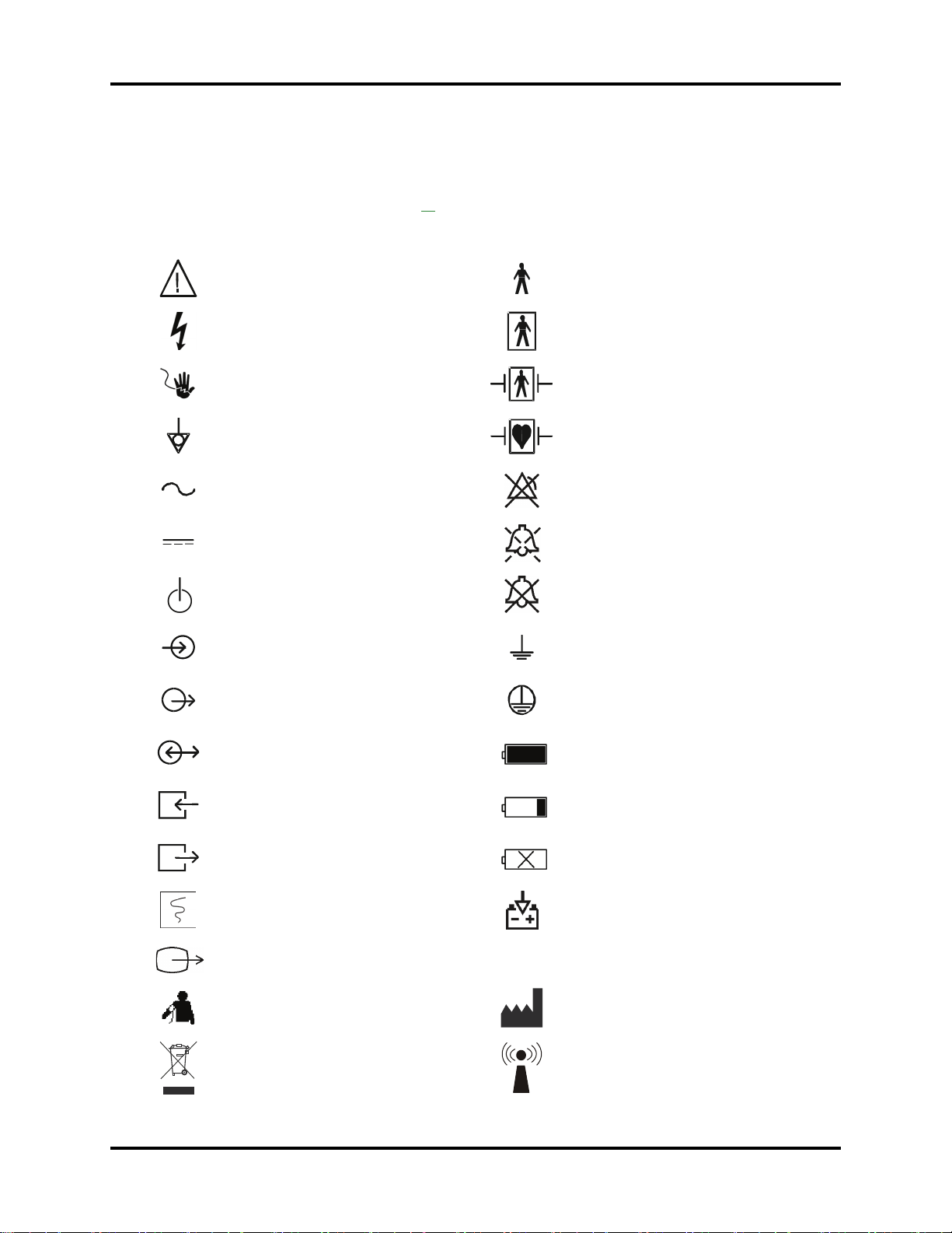
Symbols and Descriptions
SYMBOL DESCRIPTION SYMBOL DESCRIPTION
Attention, Consult Accompanying
Documents / Refer to Manual
Electrical Hazard Type BF Equipment
Shock Hazard Defibrillator Proof Type BF Equipment
Equipotentiality Defibrillator Proof Type CF Equipment
Alternating Current (AC)
Direct Current (DC)
Power On/Off
Data Input Earth (Ground)
Data Output Protective Earth (Ground)
Type B Equipment
Alarm Off Icon
Alarm Silence Icon
Alarm Silence Permanently Icon
Data Input/Output Full Battery
Gas Port Input Low Battery
Gas Port Output No Battery Present
Chart Local Printer Output Battery Charging
Video Output
NIBP Connection Manufacturer
Separate treatment from general waste at
end of life
xviii 0070- 0-0704-02 Passport V Operating Instructions
0
Interference may occur in the vicinity of
equipment marked with this symbol
Page 22
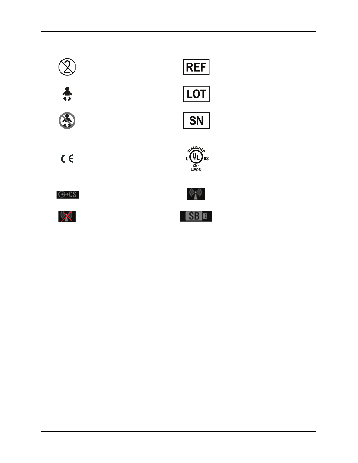
For single-patient use only, do not reuse. Manufacturer’s reference/catalogue
number
For Neonatal use Manufacturer’s batch number
Not for Neonatal use Serial number
Classified by Underwriters Laboratories
Inc. with respect to electric shock, fire
Conformité Européenne (CE) Marking of
Conformity to European Medical Device
Directive. CE
Body number
represents the Notified
XXXX
and mechanical hazards, only in
accordance with UL 60601-1, CAN/
CSA C22.2 NO.601-1, IEC 60601-1-1,
IEC 60601-2-25, IEC 60601-2-27, IEC
60601-2-30, IEC 60601-2-34, IEC
60601-2-49.
CS1 Port Connection
Wireless Enabled and not communicating
The wireless status icon indicates that the
2.4 GHz radio is activated.
SB Storage Device Connection
Passport V Operating Instructions 0070- 0-0704-02 xix
0
Page 23

This page intentionally left blank.
xx 0070- 0-0704-02 Passport V Operating Instructions
0
Page 24
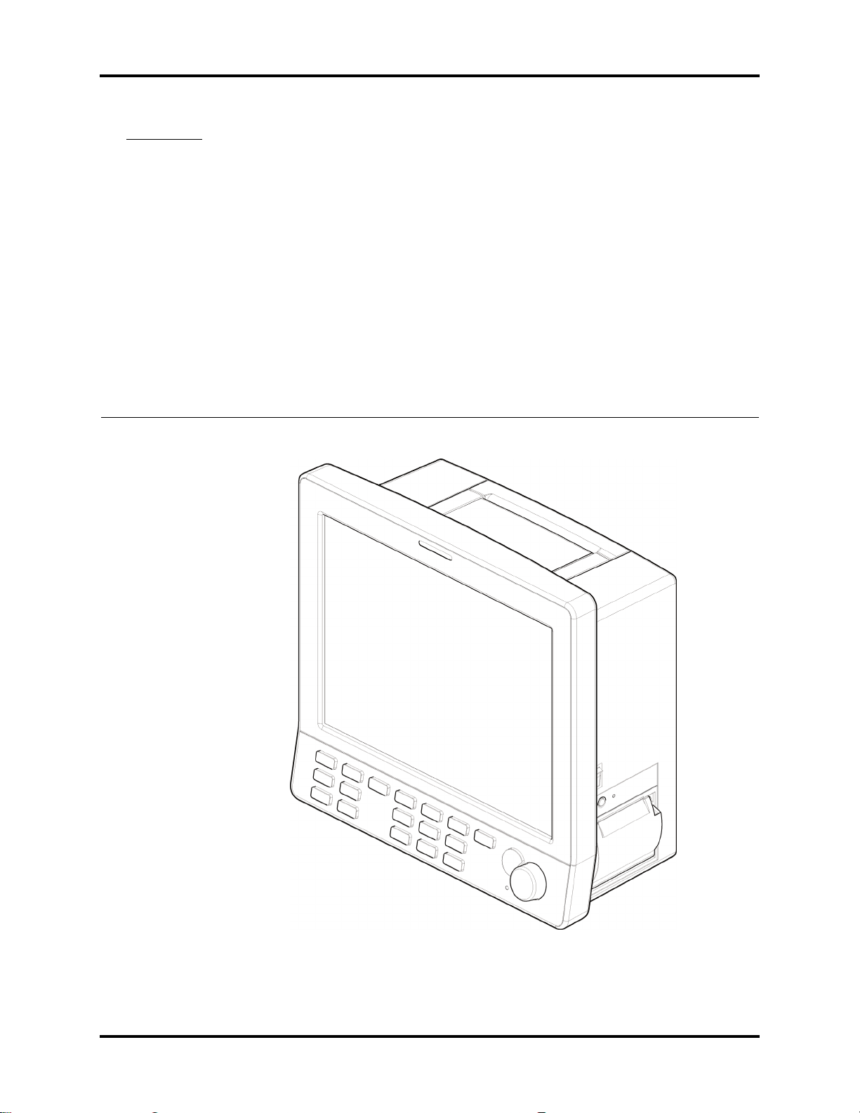
1.0
General Product Description
FIGURE 1-1 The Passport V Patient Monitor
Passport V Operating Instructions 0070- 0-0704-02 1 - 1
0
Page 25

General Product Description General Product Description
1.1 General Product Description
The Passport V is a vital signs monitor intended for intrahospital use on human patients.
The Passport V is a three (3) to eight (8) trace monitor. The unit has many features and
functions, yet is easy to use through an integrated keypad, Navigator Knob and an intuitive
menu system.
The Passport V has a 12.1 inch color display and comes standard with 3 or 5-lead ECG,
Masimo SET
IV Drug Calculations, and support for Gas Module 3 connectivity.
The Passport V may be configured to suit your department by adding software and
hardware optional features. Optional software features include ST and Arrhythmia analysis.
Optional hardware features include up to 2 Invasive Blood Pressure Channels, DPM CO
MicroStream
Local Printer, and 2.4 GHz wireless networking.
Digital displays are provided for Heart Rate, Non-invasive Blood Pressure (NIBP), Pulse
Oximetry (SpO2), Respiration Rate, and Temperature. Optional digital areas provided for
Invasive Blood Pressure (up to two), Anesthetic Agents, O
The optional local printer provides hard copies of all digital data and waveforms as well as
trend information.
®
SpO2, Non-invasive Blood Pressure, Respiration, Continuous Temperature and
®
CO2, Anesthetic Gases, DPM SpO2, Nellcor® OxiMax® SpO2, three-trace
and N2O, ST, CO2, and MAC.
2
,
2
When powered on, the self-check feature of the Passport V provides verification of proper
operation.
The Passport V monitor can be mounted on a rolling stand, a wall mount bracket, gas
machine arm, bedrail, Gas Module or operated as a tabletop instrument.
The Passport V has the capability of interfacing with Gas Modules, Remote Displays,
Defibrillators, and Nurse Call Systems.
The Passport V monitor is powered by an AC connection or internal batteries.
The Passport V provides Remote View. This feature enables the user to view the numeric
and waveform data of another patient who is being monitored at a remote location.
1 - 2 0070- 0-0704-02 Passport V Operating Instructions
0
Page 26

General Product Description Key Features
1.2 Key Features
FEATURES STANDARD OPTIONAL
Display 12.1 inch color liquid crystal
display
Automatic Sensor Detection and
Wave form Displ ay
8-trace erase bar refresh
ECG 3 or 5-lead
(I, II, III, aVR, aVL, aVF, V)
ECG Cascade Arrhythmia Analysis
ESIS Capability (3 or 5-lead)
Blood Pressure Non-Invasive Blood Pressure Up to 2 channels of Invasive Blood Pressure
SpO
2
Temperature One channel for 400 series
Respirations Lead-selectable Impedance DPM CO
Trend Tabular and Graphic trends with
Power Internal isolated power module Second lithium-ion battery
Printing Local Printer, Remote Printer
External
Interfaces
Calculation IV drug calculations
Other Soft Grip Handle Mounting kits
Masimo SET
probes
6000 trend data entries
Lithium-ion battery
Gas Module, Nurse Call systems,
DIAP communications,
Defibrillator sync, Ethernet
network
Navigator Knob Patient and monitor data transfer
Dedicated keys
®
External Remote Color Display (SVGA)
ST Analysis
DPM SpO2, Nellcor® OxiMax® SpO
, Microstream® CO
2
Gas Module with Automatic Agent ID
Wireless network
2
2
Multi-language
supported
interface
Passport V Operating Instructions 0070- 0-0704-02 1 - 3
English, French, German, Italian,
Spanish, Brazilian-Portuguese,
Russian,Dutch
0
Page 27
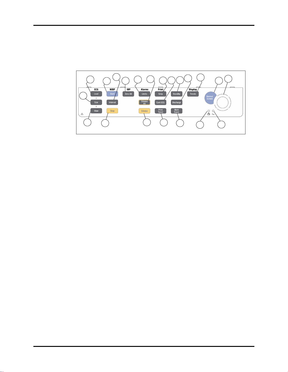
Keys and Front Panel General Product Description
1.3 Keys and Front Panel
The front panel keys are used to access many main functions quickly and easily. The figure
below shows the keys and a brief explanation follows.
1
2
3
5
4
6
7
9
8
10
11
13
12
14
16
15
17
20
18
19
21
FIGURE 1-2 Front panel keys and Navigator Knob
1. Lead
Press this key to select the next ECG lead to display in Waveform 1. Each time you press this
key, the next available ECG lead displays.
2. Size
Press this key to select the next available size of ECG for Waveform 1. Each time you press
this key, the next available ECG size displays. When the largest ECG size is displayed, the
next key press displays the smallest size.
3. View
Press this key to see multiple leads of ECG when using the 5-lead ECG cable. Press this key
repeatedly to toggle between multi-lead view, large numeric display, and normal screen.
4. Start
Press this key to begin an NIBP measurement or to begin or re-start automatic interval
measurements.
5. Interval
Press this key to modify the NIBP interval measurement time. The choices are: Off, STAT, 1
min, 2 min, 3 min, 5 min, 10 min, 15 min, 20 min, 30 min, 1 hr, 2 hr, or 4 hr.
If Off is selected, NIBP measurements can be performed manually only. If STAT is selected,
measurements will be continuous for a period of 5 minutes. Afterward, the monitor will switch
to 5-minute intervals.
6. Stop
Press this key to stop any NIBP measurement. If the interval mode is activated, pressing this
key disables the interval mode measurements. An NIBP: Idle message displays until the
interval mode is restarted.
1 - 4 0070- 0-0704-02 Passport V Operating Instructions
0
Page 28

General Product Description Keys and Front Panel
7. Zero All (with IBP option)
Press this key to set the current pressure for all invasive pressure channels to zero. This key
does not affect any channels monitoring pressure. If the zero process is not successful, one of
the following messages is displayed: Pulsatile Pressure. Cannot Zero! or Pressure
Overrange. Cannot Zero!
8. Limits
Press this key to display the Alarm Settings Menu. The Alarm Settings Menu provides
access to view or change alarm values.
9. Silence All
Press this key to suspend audio alarms on all parameters. The alarms remain suspended for a
user selected amount of time. This amount of time is set in the Alarm Setup Menu. While
the alarms are suspended, an Alarm Silence icon and message All Alarms Silenced For
X:XX mins display in the upper area of the screen. X:XX is the time remaining in minutes
and seconds. Press this key again during the suspended alarm time to re-enable the audio
alarm. If the suspend time was set to Permanent in the Alarm Setup Menu, the message
All Alarms Silenced Permanently is displayed. Note that the Permanent selection
will be available only if Enable Silence All Permanent Selection is set to “Yes” in the
Installation Menu.
10. Silence
Press this key to suspend audio alarms on all currently alarming parameters. The alarms
remain suspended for a user selected amount of time as set in the Alarm Setup Menu or
until the alarm condition is no longer present. Any new alarms that occur while the alarm
tone is silenced will disable the silence and sound the alarm tone. While the alarms are
suspended, an Alarm Silence icon and message Alarm Silenced For X:XX mins display
in the upper area of the screen.
11. Strip
Press this key to initiate a printout to the selected device.
• If the print destination is the local printer, then pressing this key will produce a print strip
of up to three (3) waveforms. The print length (16 or 32-seconds) can be set in the Print
Setup menu. Pressing this key during a print job will abort the strip printout.
• If the print destination is a remote Central Station, then pressing this key will initiate a
printout at the Central Station.
• If the print destination is a remote printer, then pressing this key will initiate a printout at
the remote printer.
12. Cont ECG
Press this key to initiate a continuous ECG 1, 2, or 3 waveform printout from the internal
printer. Press this key again to abort printing. The first three ECG waveforms displayed on the
screen are printed continuously in real-time. If only one or two ECG waveforms are displayed
on the screen, they will be printed.
Passport V Operating Instructions 0070- 0-0704-02 1 - 5
0
Page 29

Keys and Front Panel General Product Description
13. Print Trend
Press this key to initiate printing of the displayed trend. By default, the monitor’s stored trend
information will be printed by the internal printer. Pressing this key during a print job will
abort printing.
• If the print destination is a remote Central Station, then pressing this key will initiate a
trend report at the Central Station.
• If the print destination is a remote printer, then pressing this key will initiate a trend report
at the remote printer.
14. Standby
Press this key to place the Passport V into a STANDBY mode. While in STANDBY mode,
monitoring is discontinued and the alarms are in permanent suspension, interval NIBP
measurements are placed in idle mode, CO
The monitor notifies the central station and other monitors.
pump is shut off, and the display shuts down.
2
Except for the power on/off switch
and the STANDBY key, all the other hard keys on the front panel are disabled. When in the
STANDBY mode, the message To Begin Monitoring, press Standby. is displayed.
NOTE: Trend data is not cleared in the STANDBY mode. When the
STANDBY mode is released, NIBP INTERVAL is in IDLE MODE
and requires reactivation via the START key. The CO
automatically reactivates if the DPM or Microstream
is in place.
pump
2
®
sensor
Press the Standby key to exit the STANDBY mode and return to the normal screen. When
exiting from the standby mode to the monitoring mode, the monitor responds as follows:
• Restores parameter measurement: Start arrhythmia relearning. Gas modules recover the
working status before the standby mode. NIBP measurement will not start automatically.
• Restores normal data storage.
• All the alarms are activated.
• The screen becomes the one displayed before the standby mode.
• The function of auxiliary output is restored.
• The functions of input devices (such as the hard keys on the front panel) are activated.
• The monitor notifies the central station and other monitors.
15. Discharge
Press this key to discharge a patient.
16. Mark Event
Press this key to cause a time stamp event marker to be noted in the trend memory.
17. Trends
Press this key repeatedly to toggle through the following screens: Quick Trend, List Trend,
Graphic Trend, and normal screen (or OxyCRG, if the patient size is set to Neonate).
18. Normal Screen
Press this key at any time to return the screen to the normal monitoring mode. All menus are
closed.
1 - 6 0070- 0-0704-02 Passport V Operating Instructions
0
Page 30

General Product Description Keys and Front Panel
19. Navigator Knob
Rotate this knob to highlight the various menus or functions on the display. Press the center of
the knob to select the highlighted item. Selecting the item may open a menu, perform a
function, or select an option.
20. Battery Charging LED
A green LED located above the battery icon indicates that the battery charger is active. The
charger will not always be active when AC power is present. It is dependent on the battery
charge condition. The LED is not an indication of the condition of the batteries or their charge
level. Charged batteries must be installed in the monitor to ensure uninterrupted operation
while switching from AC to battery power.
21. AC Power LED
A green LED located above the AC present icon is used to indicate that the unit is connected
to the AC power.
Passport V Operating Instructions 0070- 0-0704-02 1 - 7
0
Page 31

Display General Product Description
1.4 Display
The display of the Passport V provides menus, waveforms, parameter information, and
messages. The Passport V includes a display setup function that allows customization of
the display. Preferred setup details can be programmed and saved.
The operator of the Passport V should be positioned in front of the monitor at a
comfortable distance to view all displayed waveforms and text.
Main Menus
Message
Area A
6
2
8
1
Waveform
Area
7
Message
Area B
3
Parameter
Menus
4
Numeric
Tiles
5
Status Icon
Area
FIGURE 1-3 Normal Screen Display
1. Waveform Area
The waveform area is used to display windows which contain parameter waveforms. Up to 8
waveforms may be displayed. The top waveform is always set to display the ECG waveform
and cannot be changed. By default, SpO
(Pleth) waveform will appear as the second
2
waveform. Respiration will appear as the third waveform. If pressure transducers are
plugged into the P1 and P2 ports, the screen will reformat to display the additional
waveforms. CO
will display as the fourth waveform; IBP will appear as the fifth and sixth
2
waveform. The setup can be changed to display any of the available parameters and
waveforms.
1 - 8 0070- 0-0704-02 Passport V Operating Instructions
0
Page 32

General Product Description Display
2. Main Menus
The Main Menus of the Passport V are always displayed in the upper area of the screen
and are accessed using the Navigator Knob. The Main Menu headings are Patient,
Monitor Setup, Print Setup, Parameters, and Functions. These menus enable the
user to enter patient specific data, customize the monitor, setup printing or transfer patient
data.
The Functions Menu provides the following choices: Normal Screen, Remote View,
Drug Calculator, Copy Patient Data to Storage Device, Copy Patient Data
from Storage Device, and System Information.
The Normal Screen selection returns the view to the normal screen.
There are two options for data transfer. Copy patient data to Storage Device and
Copy patient data from Storage Device options allow for the transfer of patient
specific data from monitor to monitor.
3. Parameter Menus
The Parameter Menus enable the user to review and customize various parameter display
and alarm attributes. Use the Navigator Knob to access these menus. Parameters supported
include: ECG, ST, ART, CVP, SpO
, NIBP, Resp, CO2 (optional), and Gas (optional).
2
4. Numeric Tiles
The numeric tiles display digital data for each available parameter.
5. Status Icon Area
Battery Status Icon:
When batteries are installed and the monitor is functioning on battery power, the battery
indicator provides a visual reference for the approximate charge level of the batteries. See
the following examples.
Full Battery Low Battery No Battery Present
When the battery charge is low, but not below the cutoff voltage, a flashing low battery icon
is displayed and a special low battery sound is activated.
WARNING: To ensure that alarms can sound if the Gas Module/Passport
V loses power, at least one charged battery must be
installed in the Passport V at all times.
NOTE: At least 15 minutes is available to turn off the monitor or
insert a new battery after the low battery alarm occurs.
Passport V Operating Instructions 0070- 0-0704-02 1 - 9
0
Page 33

Display General Product Description
CS Status Icon:
If displayed, the CS status icon indicates that the CS1 port is connected to another device.
CS1 Port Connection
Wireless Status Icon:
If displayed, the wireless status icon indicates that the 2.4 GHz radio is activated.
2.4 GHz Radio Activated
If displayed, the wireless status icon indicates that wireless enabled and NOT
communicating.
Wireless Enabled
NOTE: It applies to Version 01.04.00 and higher.
SB Status Icon:
If displayed, the SB status icon indicates that a storage device has been connected to the
SB port.
SB Storage Device Connection
6. Message Area A
This message area is located above the ECG waveform window. Messages regarding the
ECG/heart rate, alarm status, physiological alarms, and technical alarms are displayed
here.
• Physiological alarms are located on the left side.
• Technical alarms are located on the right side.
• ECG prompts are located at the top of waveform 1.
7. Message Area B
This message area is located below the last row of numeric tiles. Messages regarding NIBP,
IBP, printer status, system status, SpO
, CO2, and Gas Module are displayed here.
2
8. Alarm Status Icon Area
This area displays an Alarm Off icon if any alarm for a monitored parameter has been set to
Off. This area will display an Alarm Silence icon if an alarm has been silenced.
1 - 10 0070- 0-0704-02 Passport V Operating Instructions
0
Page 34

General Product Description Physical Views
1.5 Physical Views
1.5.1 Front View
4
3
1
FIGURE 1-4 Front Panel
1. Front Panel Hard Keys
Provides access to most main functions.
2. Navigator Knob
Rotates clockwise and counter-clockwise to navigate through menu selections.
It also can be pressed to select a highlighted item.
3. Display
Displays all waveforms and numeric data.
2
4. Alarm Light
Indicates that an alarm has been activated.Alarm Light (not shown). The WARNING (or
Priority 1) LED is red. The CAUTION (or Priority 2) LED is yellow.
Passport V Operating Instructions 0070- 0-0704-02 1 - 11
0
Page 35

Physical Views General Product Description
1.5.2 Rear View
1
MP1
SB1
SB2
RD1
CS1
SP1
SP2
4
2
3
FIGURE 1-5 Rear Panel
1. Soft Grip Handle
Provides a secure method to carry the monitor.
2. AC Receptacle (with an integrated cord retension clip)
Provides an inlet for an AC power cord.
3. Equipotential Lug
Provides equipotential grounding of hospital equipment.
4. Main I/O Connector Ports
Area dedicated for the use of an optional communication port.
• MP1: Allows connectivity to one of the following: Nurse Call or Defibrillator.
• SB1, SB2: Allows copying and transferring of patient data and user settings.
• RD1: Allows duplicate display of the main display on an SVGA-compatible monitor.
• CS1: Allows connectivity via an RJ45-based network.
• SP1, SP2: Allows connectivity to Gas Module 3 and DIAP.
1 - 12 0070- 0-0704-02 Passport V Operating Instructions
0
Page 36

General Product Description Physical Views
1.5.3 Left Side Panel
1
8
2
3
4
9
5
7
6
FIGURE 1-6 Left Side Panel
1. P1 Connector (optional)
2. P2 Connector (optional)
3. T1 Connector
4. ECG/EKG Connector
5. SpO2 Connector (Masimo or Nellcor shown in figure)
6. NIBP Rectus Connector
7. Battery Compartment
8. CO
9. CO
Input (Optional DPM CO2 shown in figure)
2
Exhaust Connector
2
Passport V Operating Instructions 0070- 0-0704-02 1 - 13
0
Page 37

Physical Views General Product Description
1.5.4 Right Side Panel
1
2
FIGURE 1-7 Right Side Panel
1. Power Switch
A momentary switch that turns power ON or OFF but does not prevent charging of the
batteries. Press the top of the switch once to turn the unit ON. Press the top of the switch
again to turn the unit OFF.
2. Local Printer (optional)
A thermal strip chart local printer with integral paper spool.
1 - 14 0070- 0-0704-02 Passport V Operating Instructions
0
Page 38

General Product Description Physical Views
1.5.5 Top View
1
FIGURE 1-8 Top Vie w
1. Soft Grip Module Handle
This integrated grip handle is used for carrying the Passport V.
WARNING: Do not carry the Passport V using the integrated grip handle
if the unit is mounted to another item (e.g., a rolling stand
or Gas Module 3).
Passport V Operating Instructions 0070- 0-0704-02 1 - 15
0
Page 39

Physical Views General Product Description
This page intentionally left blank.
1 - 16 0070- 0-0704-02 Passport V Operating Instructions
0
Page 40

2.0
System Configuration
2.1 Installation Menu
The Installation Menu allows the user to change and save default configuration settings for
the Passport V, such as date format, time format, and temperature units. All the hard keys
are disabled (except the Navigator Knob) in Installation Mode.
FIGURE 2-1 Installation Menu
Passport V Operating Instructions 0070- 0-0704-02 2 - 1
0
Page 41

Installation Menu System Configuration
To access the Installation Menu:
1. Turn off the Passport V.
2. Press and hold the Discharge key on the front panel.
Simultaneously, power up the Passport V monitor.
3. Release the Discharge key when the Installation Menu is displayed.
4. Set each item as necessary using the Navigator Knob.
5. To save all of the chosen settings, choose “Save Current” before leaving this menu.
6. To return to normal operating mode, cycle power to the Passport V monitor.
The following table describes the Installation Menu structure:
MENU TITLE
ON SCREEN MENU CHOICES DEFAULT COMMENTS
Save Current Select to save current
settings as defaults.
Select Language ENGLISH
Date Format Y/M/D
Time Format 12 hour
NIBP Timeout 15 min
Temperature Units °F
Weight Units lbs
Height Units inches
Units mmHg
CO
2
ECG Standard AHA
FRENCH
GERMAN
ITALIAN
SPANISH
PORTUGUESE
RUSSIAN
DUTCH
M/D/Y
D/M/Y
24 hour
30 min
45 min
60 min
°C
kg
cm
%
kPa
IEC
Set up at factory Select to change language.
M/D/Y Select to change date
12 hour Select to change time
15 min Select to change NIBP time
°F Select to change
lbs Select to change weight
inches Select to change height
mmHg Select to change CO
AHA Select to change standard
format.
format.
out.
temperature units.
Changing temperature
units will cause temperature
alarm limits to be restored
to default values.
units.
units.
2
units. Changing CO
will cause CO
to be restored to default
values.
for ECG.
units
2
alarm limits
2
2 - 2 0070- 0-0704-02 Passport V Operating Instructions
0
Page 42

System Configuration Installation Menu
MENU TITLE
ON SCREEN MENU CHOICES DEFAULT COMMENTS
Notch Filter 50 Hz
60 Hz
60 Hz Select to change notch filter
for ECG.
Off
ESU Filter Auto
Disable
SpO
Audio
Sensor Off
2
Off
Once
Repeat
Tones Standard Tones
SpO
2
Enable Arrhythmia All
Off Selection
Alternate Tones
Yes
No
Auto Select to change the ESU
filter.
Off Select to change the SpO2
Sensor Off Audio alert
type.
Standard Tones Select to change the SpO2
tones.
No Select to enable or disable
the Arrhythmia All Off
menu selection.
Apnea Latch On
Off
Enable Silence All
Permanent Selection
Yes
No
On Select to turn apnea alarm
latching on or off.
No Select to enable or disable
the Permanent Audio Off
menu selection.
Auxiliary Output Nurse call
Analog Output
Defib Sync
Nurse Call Mode Normally Open
Normally Close
Set up Serial Port 1 None
Nurse Call Select to change the
function of the Auxiliary
Output interface.
Normally Open Select to change the type
of Nurse Call system
None Select to set up comm port.
DIAP
Gas Module
Set up Serial Port 2 None
None Select to set up comm port.
DIAP
Gas Module
Copy Monitor Defaults
to Storage Device
Copy Monitor Defaults
from Storage Device
Select to copy monitor
defaults to Storage Device.
Select to copy monitor
defaults from Storage
Device.
Re-boot in demo mode No
Yes
No Set to “YES” to start the
monitor in demonstration
mode on next power-up.
Normal monitoring will
resume after cycling power
in demonstration mode.
Restore factory
defaults
Advanced Installation
Setup
Select to restore factory
defaults
Select to access Advanced
Installation Setup Menu.
Change Password Select to change
password.
Options Select to add/view
options.
Passport V Operating Instructions 0070- 0-0704-02 2 - 3
0
Page 43

Advanced Installation Setup Menu (Network) System Configuration
2.2 Advanced Installation Setup Menu (Network)
Use the Advanced Installation Setup Menu for network configuration of the Passport V.
FIGURE 2-2 Advanced Installation Setup Menu
To access the Advanced Installation Setup Menu:
1. Turn off the Passport V.
2. Press and hold the Discharge key on the front panel.
Simultaneously, power up the Passport V monitor.
3. Release the Discharge key when the Installation Menu is displayed.
4. Rotate the Navigator Knob to navigate and select the Advanced Installation Setup
Menu.
5. Set each item as necessary using the Navigator Knob.
6. To save all of the chosen settings, select Previous Menu
7. To return to normal operating mode, cycle power to the Passport V monitor.
The following table describes the Advanced Installation Setup Menu structure:
〉 Save Current.
2 - 4 0070- 0-0704-02 Passport V Operating Instructions
0
Page 44

System Configuration Advanced Installation Setup Menu (Network)
MENU TITLE
ON SCREEN MENU CHOICES DEFAULT COMMENTS
Previous Menu Select to return to previous
menu.
DIAP Baud Rate 9600
19200
Enable Network Wired
Wireless
Connect To Central
Station
IP Address 7.6.6.50 Select to set up the IP
Subnet Mask ID 255.255.255.0 Select to set up subnet
Configure Wireless AP Press to enable or disable
Search Printer Select to search for printers
Select Printer Select to change the target
Paper Size Select to change the printer
Device ID Set at the factory. Not user-
Yes
No
9600 Select to change DIAP
protocol baud rate.
Wired Select to change the type
of communications with
Panorama.
Wireless is always
displayed as an option, but
will function only if the
wireless option is installed.
No Select No to disable
communication with the
Central Station.
Select Yes to enable
communication with the
Central Station. If
communication has failed,
the message “No
Arrhythmia Detection at
Central” is displayed.
address.
mask ID.
the operation of
configuring wireless AP.
on the network.
printer already found.
paper size.
selectable.
Passport V Operating Instructions 0070- 0-0704-02 2 - 5
0
Page 45

Monitor Setup Menu System Configuration
2.3 Monitor Setup Menu
Select the Monitor Setup Menu to configure audio and display settings.
FIGURE 2-3 Monitor Setup Menu
To access the Monitor Setup Menu:
1. Power up the Passport V. The normal screen is displayed.
2. Rotate the Navigator Knob to Monitor Setup. Press the knob to select it.
3. Configure the settings as desired.
4. To exit, press the Normal Screen key on the front panel.
The following table describes the Monitor Setup Menu selections:
MENU TITLE
ON SCREEN MENU CHOICES DEFAULT COMMENTS
Normal Screen Select to return to Normal Screen (or
Display Setup Select to make changes to the display
Alarm Volume low to high volume Mid-level Select to change alarm volume.
Beep Volume silence to high volume Mid-level Select to change systole beep volume.
Color Select to access Color Setup Menu.
Advanced Setup Select to access Advanced Setup
press the Normal Screen key on the
front panel).
format. Save as defaults if desired.
Menu.
2 - 6 0070- 0-0704-02 Passport V Operating Instructions
0
Page 46

System Configuration Advanced Setup
2.4 Advanced Setup
Select the Advanced Setup to configure date, time and other settings.
FIGURE 2-4 Advanced Setup
To access the Advanced Setup:
1. Power up the Passport V. The normal screen is displayed.
2. Rotate the Navigator Knob to Monitor Setup
select it.
3. Configure the settings as desired.
4. To exit, press the Normal Screen key on the front panel.
The following table describes the Advanced Setup selections:
MENU TITLE
ON SCREEN MENU CHOICES DEFAULT COMMENTS
Previous Menu Select to return to the
Set Date Select to set date.
Set Time Select to set time.
NIBP Start Mode Interval Mode
Timer Mode
〉 Advanced Setup. Press the knob to
previous menu.
Interval Mode Select Interval mode to
synchronize NIBP Start
with the integral clock.
Select Timer Mode fo
synchronize the NIBP start
with the interval selected in
relation to the real time
clock.
Passport V Operating Instructions 0070- 0-0704-02 2 - 7
0
Page 47

Advanced Setup System Configuration
MENU TITLE
ON SCREEN MENU CHOICES DEFAULT COMMENTS
Nurse Call Off
1 second
Continuous
Arrhythmia Menu Select to open the
Restore User Defaults Select to load user defaults
Save Current Select to save current
Off Select to choose nurse call
activation time.
Arrhythmia Menu.
as current settings.
settings as defaults. Enter
password.
2.4.1 How to Set the Clock / Date and Time
The date and time are set in the Monitor Setup Menu 〉 Advanced Setup
1. Using the Navigator Knob, highlight Monitor Setup. Press the Navigator Knob to
open the menu.
2. Use the Navigator Knob to select Advanced Setup, then select either Set Date or
Set Time.
3. Turn the Navigator Knob to select a new setting. Once the desired choice is highlighted,
press the Navigator Knob.
4. This setting is saved when Ye s is selected via the confirmation prompt.
2.4.2 Transferring Monitor Default Settings
When installing several Passport V monitors with identical display and alarm settings it is
not necessary to set each unit separately. A DPM storage device may be used to copy the
settings from monitor to monitor.
NOTE: Use only storage devices supplied by Mindray.
CAUTION: Do not unplug the storage device from any of the SB ports
on the Passport V while transferring data, as indicated on
the menu or prompt areas of the monitor. Data may be lost
or corrupted and the storage device may become damaged.
2 - 8 0070- 0-0704-02 Passport V Operating Instructions
0
Page 48

System Configuration Configuration Management
2.5 Configuration Management
If the monitor is inadvertently powered down (due to power failure or battery depletion),
monitor settings are recovered as follows:
• If the monitor is restarted within 60 seconds, the latest user-settings will be restored.
• If the monitor is restarted after 60 but before 120 seconds, the settings restored may be
either the latest user-settings or the user-saved settings.
• If the monitor is restarted after 120 seconds, the user-saved configurations will be
restored.
Passport V Operating Instructions 0070- 0-0704-02 2 - 9
0
Page 49

Configuration Management System Configuration
This page intentionally left blank.
2 - 10 0070- 0-0704-02 Passport V Operating Instructions
0
Page 50

3.0
Patient Management
3.1 Description
The Passport V comes with default factory settings which enable you to begin monitoring
without setting any of the waveforms, parameters, alarms, or functions. However, all of these
settings can be changed for specific patient or departmental needs.
Certain operating characteristics are based on the selected patient size (e.g. NIBP start
pressure). The patient size selection should be matched to the actual patient before
monitoring begins.
Passport V Operating Instructions 0070- 0-0704-02 3 - 1
0
Page 51

Setting-up Patients Patient Management
3.2 Setting-up Patients
1. Turn the monitor on using the ON/OFF switch. Ensure the previous patient’s data has
been removed from the monitor by discharging previous patient.
2. Connect the patient to the monitor, apply appropriate accessories such as ECG
electrodes, blood pressure cuff, etc.
3. Enter patient information into the Passport V via the Patient Menu, check patient
size.
4. If desired, press the START key to initiate a non-invasive blood pressure measurement.
3.2.1 Patient Menu
To display the Patient Menu:
1. On the front panel:
Press the Normal Screen key to return to the normal screen.
2. On the normal screen:
Select Patient by rotating the Navigator Knob.
3. Use the Navigator Knob to enter patient information. Monitor settings are stored for
each patient size.
NOTE: Verify monitoring settings when the patient size is changed.
FIGURE 3-1 Patient Menu
3 - 2 0070- 0-0704-02 Passport V Operating Instructions
0
Page 52

Patient Management Setting-up Patients
Patient Menu
MENU ITEM SELECTIONS COMMENTS
Normal Screen — Select to return to Normal Screen (or press the
Normal Screen key on the front panel).
Patient Size Adult (default)
Pediatric
Neonate
Gender Unspecified (default)
Male
Female
Date of Birth Unspecified (default) Select to enter or change date of birth.
First Name Select to enter or change patient’s first name.
Last Name Select to enter or change patient’s last name.
ID # Select to enter or change Patient ID.
Bed # Select to enter or change patient bed number.
Height Unspecified (default) Select to enter or change patient height.
Weight Unspecified (default) Select to enter or change patient weight.
Drug Calculator Select to open Drug Calculation Menu.
Discharge Select to discharge patient from monitor.
Note: When changing Patient Size, some patient
info may need to be re-entered.
Select to enter or change patient gender.
Entering a Patient’s First / Last Name, ID Number and Bed Number
To enter the patient’s First Name, Last Name, ID Number and Bed Number
complete the following steps:
1. Open the Patient Menu and scroll down through the menu using the Navigator
Knob.
2. Select the patient data you wish to enter or change.
3. Press the Navigator Knob and a keypad will appear on the screen.
4. To enter patient information highlight the appropriate characters.
5. When finished entering the data select Done and press the Navigator Knob to close
the keypad.
6. The patient information will appear in the upper right hand corner of the display. This
data will also appear on printouts.
NOTE: Since Remote View requires selecting a “Bed #”, a unique
number for each bed should be used. The following
standard format for this demographic is recommended:
Passport V Operating Instructions 0070- 0-0704-02 3 - 3
0
Page 53

Discharging a Patient Patient Management
• Start the Bed # with a room number that has a fixed number of digits. For example,
if the maximum number of digits that is used in numbering the rooms is 4, then for
room 102, a leading zero would be added to get the 4th digit - 0102.
• Follow the room number with a letter to identify the particular bed within the room.
For example, a room with 2 beds would have bed A and bed B.
• An example of a complete “Bed #”: Bed B in room 513 (in a facility where there
are up to 4 digits in a room number) would be identified as 0513B.
Entering a Patient’s Date of Birth
To enter the patient’s Date of Birth complete the following steps:
1. Open the Patient Menu and scroll down through the menu using the Navigator
Knob.
2. Select Date of Birth from the menu. Press the Navigator Knob and a pop-up
window will emerge with day, month and year choices for Date of Birth.
3. To enter the patient’s Date of Birth, turn the Navigator Knob and scroll until you
reach the desired dates.
4. When finished with the Date of Birth, press the Navigator Knob to return to the
Patient Menu.
3.3 Discharging a Patient
To discharge a patient from the Passport V:
1. On the front panel:
Press the Discharge key
or
On the normal screen:
Select Patient
Discharging a patient from the Passport V clears the following:
• Patient information (except Patient Size and Bed No.)
• Physiological alarms and technical alarms
• Prompt messages irrelevent with the patient management
• Corresponding history data (includes Trend data, Events, OxyCRG Trend data, Dose
calculations)
• Operations in process (includes local printing and NIBP measurement)
〉 Discharge
3 - 4 0070- 0-0704-02 Passport V Operating Instructions
0
Page 54

Patient Management Data Transfer
3.4 Data Transfer
3.4.1 Transferring User Configuration
Patient configuration and data can be transferred to and from the Passport V via a DPM
storage device inserted into the SB1 or SB2 port, located in the back of the unit. The
maximum time of data download or upload is about 1 min.
The transferred patient data includes the following:
• Patient demographics (not including Bed No.)
• Trend & Event Data
NOTE: Newly generated trend or event data, or on-going changed
patient demographics may not be transferred during the
downloading process.
CAUTION: Do not unplug the storage device from any of the SB ports
on the Passport V while transferring data, as indicated on
the menu or prompt areas of the monitor. Data may be lost
or corrupted and the storage device may become damaged.
Passport V Operating Instructions 0070- 0-0704-02 3 - 5
0
Page 55

Remote View Patient Management
3.5 Remote View
The Remote View selection enables the user to view the numeric and waveform data of
another patient monitored by a different Passport V at a remote location.
To display Remote View:
On the normal screen:
Select Functions
The Remote View feature allows the simultaneous display of data from two patients on a
single monitor. The monitor at the user’s current location is defined as the host monitor. While
maintaining visibility of the primary patient at the host monitor, the Remote View Menu
enables the user to view the numeric data and two selectable waveforms of another patient
who is being monitored at a remote location. The monitor at the remote location is defined as
the remote monitor. Visual and audio alarms occurring at the remote monitor are also
received through the Remote View Menu at the host monitor
.
〉 Remote View.
FIGURE 3-2 Remote View Menu on Main Display
The “Enable Network” option in Installation Menu
Menu must be set to “Wired” or “Wireless” for Remote View capability to be available.
Only Passport V monitors on an approved hardwired or wireless network can be viewed
remotely.
NOTE: Unstable wireless signals may be caused by the monitor
operating beyond the network coverage, interference from
nearby equipment, or by exceeding network capacity limit.
3 - 6 0070- 0-0704-02 Passport V Operating Instructions
0
〉 Advanced Installation Setup
Page 56

Patient Management Remote View
NOTE: Remote View function is not available between wireless
monitors, nor for wireless monitors to view wired monitors.
Remote View function is available between wired monitors,
or for wired monitors to view wireless monitors.
All Remote View controls are contained within the Remote View Menu. Opening other
menus from the monitor’s keypad, or pressing the Normal Screen key, will close the
Remote View Menu.
The Remote View Menu displays data as follows:
• The waveforms that are displayed are user-selectable through the Remote View
Setup Menu, as described in the table on page 3-8. Corresponding numeric tiles
are displayed to the right of the waveforms. The numeric data for a maximum of fifteen
(15) parameters that are not related to the waveforms is displayed in the “Numeric
Data Area” located directly below the waveforms.
• The colors of the waveforms and all numeric data correspond to the settings of the host
monitor (not the remote monitor).
• When numeric data for a particular parameter is unavailable, dashes (– – –) are
displayed.
• If a high or low alarm limit has not been set, an Alarm Off icon is displayed.
• Remote View alarms follow the alarm settings at the remote monitor, displaying in a
priority-appropriate, reverse-video color.
• If the remote monitor is placed into Standby mode, the message “In Standby” is
displayed in the Remote View Window.
NOTE: Respiration alarm text messages are also displayed in the
displayed in the message area (upper part) of the Remote
View Menu window as follows:
• If Apnea is detected, the message “APNEA” is displayed.
• If CVA is detected, the message “CVA” is displayed.
• If high impedance is detected from the ECG electrodes, the
message “CHK LEAD” is displayed.
The Remote View Menu also provides the following menu choices: Normal Screen,
Select Beds, Setup, Remote Silence, Remote Silence All, and Remote Print.
1. Normal Screen — this selection removes the Remote View Menu from the display.
2. Select Beds — this selection opens the Select Beds menu from which beds may be
selected to be included in the care group. All networked beds will be in que but only 8
can be selected.
Passport V Operating Instructions 0070- 0-0704-02 3 - 7
0
Page 57

Remote View Patient Management
3. Setup — this selection opens the Remote View Setup Menu shown in FIGURE 3-3.
This menu enables the user to configure the display and functionality of the Remote
View Menu.
FIGURE 3-3 Remote View Setup Menu
The following table provides a listing of the Remote View Setup Menu items:
Remote View Setup Menu
MENU ITEM SELECTIONS COMMENTS
Previous Menu Select to return to previous menu.
Waveform 1 All waveforms available
on the remote monitor.
Waveform 2 All waveforms available
Remote Silence For 1 min
Remote Silence
All For
* These selections will not be available if the language chosen in the Installation Menu is French.
on the remote monitor.
2 min (default)
3 min*
5min*
10 min*
Permanent*
1 min
2min (default)
3 min*
5min*
10 min*
Only waveforms available on the remote monitor
will be listed as selections for this menu item. The
menu selections for Wave 1 will not include the
waveform that is currently selected as Wave 2.
Only waveforms available on the remote monitor
will be listed as selections for this menu item. The
menu selections for Wave 2 will not include the
waveform that is currently selected as Wave 1.
Select to choose duration of Remote Silence.
Select to choose duration of Remote Silence All.
3 - 8 0070- 0-0704-02 Passport V Operating Instructions
0
Page 58

Patient Management Remote View
4. Remote Silence / Remote Silence All — this selection silences the audio portion of
a remote alarm for the duration that is selected from the Remote Silence For /
Remote Silence All For list in the Remote View Setup Menu. The factory default
is 2 minutes. While the audio alarm is silenced:
• The visual alarm indicators remain displayed.
• The message ALARMS SILENCED FOR X:XX mins is displayed in the message
area of the Remote View Menu. The X:XX in the message is a digital timer for the
silence time remaining.
• If a new remote alarm occurs during this time, the current alarm will remain silenced
while its digital timer continues to count down, and the new alarm tone will sound.
• An Alarm Silence icon is displayed in the top left of the Remote View window.
•If Remote Silence is selected again, the digital timer is reset.
NOTE: The Remote Silence selection silences only the alarms
indicated in the Remote View Menu. It does not silence the
primary patient's alarms or alarm sounds at the remote
location.
5. Remote Print – Select to request a remote print.
6. Remote Silence All — this selection silences the audio alarm tones of all remote
alarms for the duration that is selected from the Remote Silence All For list in the
Remote View Setup Menu. The factory default is 2 minutes. While the audio alarms
are silenced:
• the visual alarm indicators remain displayed
• the message All Alarms Silenced For X:XX mins is displayed in the message
area of the Remote View Menu. The X:XX in the message is a digital timer for the
silence time remaining
NOTE: If “Permanent” is selected from the Remote Silence All For
list, “All Alarms Silenced Permanently” is displayed in the
message area of the Remote View Menu.
• an Alarm Silence icon (a crossed bell) is displayed in the numeric tiles and in the
“Numeric Data Area”
If Remote Silence All is selected again, the audio alarm tones are re-enabled.
NOTE: The Remote Silence All selection silences only the alarms
indicated in the Remote View Menu. It does not silence the
primary patient's alarms or alarm sounds at the remote
location.
7. Remote Print — this selection sends a print request to the remote monitor. The printout
will be as configured in the Print Setup menu of the remote monitor.
NOTE: When a Remote Print is requested, there is no indication that
the printout was completed as requested. The user should
verify the successful print at the printer.
Passport V Operating Instructions 0070- 0-0704-02 3 - 9
0
Page 59

Remote View Patient Management
Remote View Message Area
• If more than one message is being received, they are alternately displayed.
• All arrhythmia alarms, priority one alarms, and priority two alarms generate the
appropriate audio alerts at the host monitor, and the associated alarm text messages
are displayed in the Remote View Message Area. See section 4.7 (pg. 4-25)
"Arrhythmia Alarms (optional)" for the specific arrhythmia alarm text messages that
can be displayed.
NOTE: The Lethal Arrhythmia alarms (V-Tach, V-Fib, and Asystole)
are latched alarms. They cannot be acknowledged by
selecting "Remote Silence "or "Remote Silence All" in the
"Remote View Menu". If an alarm is acknowledged while a
lethal condition still exists, the audio alert of the alarm will
be silenced for XX minutes, where XX is the number
minutes selected in “Remote View Menu” 〉 “Setup” 〉
“Remote Silence For” or “Remote Silence All For”. However,
the visual alert of the alarm and the alarm message will
continue to remain active in the Remote View Message
Area.
If a new lethal condition occurs while the initial lethal alarm
is silenced, the new lethal alarm will not break through but
not be silenced. If the lethal condition is resolved while the
alarm is silenced, the alarm will be terminated.
• All alarm messages for parameters are displayed in the Message Area of the Remote
View Menu window.
• If Apnea is detected, the message “Apnea” is displayed.
• If CVA is detected, the message “CVA” is displayed.
• Remote View displays Technological Alarm messages and Physiological Alarm
messages.
3 - 10 0070- 0-0704-02 Passport V Operating Instructions
0
Page 60

Patient Management Monitor/Display Troubleshooting
3.6 Monitor/Display Troubleshooting
MESSAGE/PROBLEM REASON SOLUTION
No trace for a desired
parameter
Display Appears to be Off Mains power switch may not be
Disabled Alarm Tone Silence key pressed. Check for alarm silence symbol
Cooling Fan Failure The unit running on AC power
Patient Information did not
appear on display
Incorrect Date or Time Data not entered or entered
Improper attachment of
transducer or cable to monitor.
Faulty transducer or cable. Try a new transducer or cable.
on.
Unit may not be plugged into an
AC outlet.
If used as a portable, battery
pack may be drained.
Monitor or display is damaged. Contact Customer Support.
Beep volume low. Increase beep volume.
and the cooling fan is not
operational.
No data entered. Enter proper patient data.
Done was not selected from
keypad after entering data.
incorrectly.
Check transducer / cable
connection.
Press mains power switch on
side panel.
Check power cord (Is it plugged
in?)
If battery pack is drained, plug
into an AC outlet to recharge the
battery. A period of 5.5 hours
(monitor OFF) or 8.5 hours
(monitor ON) is required for a
full charge of lithium-ion
batteries.
and message.
Contact Customer Support.
Go to the proper keypad enter
data, select Done when
finished.
Follow instructions from “How
to Set the Clock / Date and
Time”.
Passport V Operating Instructions 0070- 0-0704-02 3 - 11
0
Page 61

Monitor/Display Troubleshooting Patient Management
This page intentionally left blank.
3 - 12 0070- 0-0704-02 Passport V Operating Instructions
0
Page 62

4.0
ECG Monitoring
4.1 Description
ECG is a continuous waveform of a patient's cardiac electrical activity. An ECG waveform
will display in the first waveform area of the Passport V.
The quality of an ECG signal is directly affected by electrode site skin preparation, electrode
patch quality and ECG lead placement. If artifact is present on the ECG waveform, then the
arrhythmia processing, alarm processing, and quality of the monitoring function may be
affected. The presence of artifact can prevent the monitor from establishing an accurate ECG
reference waveform, increasing the difficulty experienced in assessing the ECG rhythm.
Optimizing the ECG signal is imperative for accurate monitoring. Use high quality
electrodes, designed to acquire the ECG with excellent base line stability, recovery from
defibrillation and minimum artifact from patient movement.
With the Passport V, ECG can be obtained by using a 3- or 5-lead ECG cable in
conjunction with a 3- or 5-lead set and skin electrodes. For best performance and safety,
inspect the ECG cables and electrodes daily.
Features:
• Provides the function of ECG1 cascade display on the normally monitored screen.
•The Passport V supports the Mortara algorithm (V3.2.8).
• Supports 3- and 5-lead configuration and automatic identification of lead configuration.
• The ECG algorithm includes up to three parts: HR calculation, ST analysis (if installed)
and ARR analysis (if installed).
• Displays HR, PVCs and ST segment parameters and ECG waveforms (if installed).
• The ECG waveforms can be displayed normally or in All ECG View (via View key)
when a 5-lead leadset is in use.
• When using a 5-lead cable, 3-lead configuration will be selected automatically if the RL
lead becomes detached from the patient.
Passport V Operating Instructions 0070- 0-0704-02 4 - 1
0
Page 63

ECG Screens ECG Monitoring
4.2 ECG Screens
4.2.1 Numeric Tile: ECG
The ECG numeric tile displays the following:
• ECG label
• HR value, HR unit, HR alarm limits
• PVCs parameter name, PVCs value (not displayed when arrhythmia is OFF or not
installed)
• ST segment value (not displayed when ST segment analysis is OFF and Combine HR/ST
is set to Off or not installed)
•HR source
NOTE: In Large Numeric Screen, ST values and PVC/min are not
displayed in the ECG numeric tile.
ECG Label HR Unit
High Alarm Limit
Low Alarm Limit
HR Measured Value
PVCs Measured Value
HR Source
FIGURE 4-1 ECG numeric tile without ST displayed
ECG Label HR Unit
High Alarm Limit
Low Alarm Limit
HR Measured Value
ST Unit
PVCs Measured Value
HR Source
ST Values
FIGURE 4-2 ECG numeric tile with ST displayed
4 - 2 0070- 0-0704-02 Passport V Operating Instructions
0
Page 64

ECG Monitoring ECG Screens
4.2.2 Waveform: ECG
The ECG waveform tile displays the following:
• Every ECG waveform area displays ECG lead name, ECG scale, and filter mode.
• A pacer marker is displayed when an external pace pulse is detected.
• ECG Prompt Messages are displayed in the top of ECG1 waveform area:
Message "Pacer Reject On" is displayed in the right top of waveform area.
Other ECG prompt messages are displayed in the middle top of ECG1 waveform area.
FIGURE 4-3 ECG waveform, 3-lead normal monitoring (cascade is turned on)
FIGURE 4-4 ECG waveform, 5-lead normal monitoring (2 channel)
Passport V Operating Instructions 0070- 0-0704-02 4 - 3
0
Page 65

ECG Screens ECG Monitoring
FIGURE 4-5 ECG waveform, 1mV scale overrange
4 - 4 0070- 0-0704-02 Passport V Operating Instructions
0
Page 66

ECG Monitoring Front Panel: ECG Keys
4.3 Front Panel: ECG Keys
ECG Keys (Front Panel)
KEY COMMENTS
LEAD Press to change ECG1 lead selection.
The ECG1 menu selection in ECG Menu has the same function.
In All ECG View, this key is disabled.
SIZE Press to change ECG1 waveform size.
VIEW Press to display the All ECG View screen. In All ECG View, the order of the
The ECG1 Size menu option in the ECG Sizes Menu has the same function.
In All ECG View, this key is disabled.
waveforms displayed is I, II, III, aVR, aVL, aVF, V.
Press this key repeatedly to toggle between multi-lead view, large numeric display,
and normal screen.
When returning to Normal Screen from All ECG View, the order of the ECG
waveforms is displayed as configured in the ECG Menu.
Passport V Operating Instructions 0070- 0-0704-02 4 - 5
0
Page 67

Menus: ECG Main and Submenus ECG Monitoring
4.4 Menus: ECG Main and Submenus
4.4.1 ECG Menu
FIGURE 4-6 ECG Menu
To display the ECG Menu:
1. On the front panel:
Press the Normal Screen key to return to the normal screen.
2. On the normal screen:
Select Parameters
or
Select the ECG tile.
3. To exit, press the Normal Screen key on the front panel.
4 - 6 0070- 0-0704-02 Passport V Operating Instructions
〉 ECG
0
Page 68

ECG Monitoring Menus: ECG Main and Submenus
ECG Menu
MENU ITEM SELECTIONS COMMENTS
Normal Screen — Select to return to Normal Screen (or press the
Normal Screen key on the front panel).
ECG 1
ECG 2
ECG 3
ECG 4
ECG 5
ECG 6
Speed
Arrhythmia Menu Select to open the Arrhythmia Menu.
ST Menu Select to open the ST Menu.
Relearn — Select to manually initiate the relearning process for
For 3-lead leadset:
I, II, III
For 5-lead leadset:
I, II, III, aVR, aVL,
aVF, V
Defaults:
ECG 1 = II
ECG 2 = I
ECG 3 = V
ECG 4 = aVR
ECG 5 = aVL
ECG 6 = aVF
6.25 mm/s
12.5 mm/s
25 mm/s (default)
50 mm/s
Select to change ECG lead to be analyzed.
When a 3-lead configuration is detected, only ECG1
is displayed.
When a 5-lead configuration is detected, ECG1 to
ECG6 can be displayed.
In Normal screen, the ECG lead displayed can be
selected as required.
In All ECG View, the ECG1 to ECG6 options can
be selected as required.
The effect of 3-lead and 5-lead switchover:
5-lead to 3-lead: If ECG1 is I/II/III, then ECG1 is
unchanged. Otherwise, automatically change to II.
3-lead to 5-lead: ECG1to ECG6 are unchanged from
the previous 5-lead setting.
Select to change the trace speed (mm/s) of the ECG
waveform. Applies to all ECG leads.
Available only if Arrhythmia option is installed.
Disabled if Patient Size = Neonate.
Available only if ST option is installed.
Disabled if Patient Size = Neonate.
ST Measurements or Arrhythmia Analysis.
Relearn is disabled if at least one of the following:
• Patient Size = Neonate.
• ST Analysis and Arrhythmia = Off.
• ST Analysis and Arrhythmia are not configured.
After relearning is started, arrhythmia relearning and
ST relearning are performed simultaneously. The
arrhythmia and ST analysis templates are recreated
and the message “Relearning...” is displayed. During
relearning, ST and PVCs are displayed as “– – –“.
Arrhythmia relearning should be automatically
started when:
• Lead type is changed.
• ECG lead wires are reconnected to the patient.
• Analysis lead is changed.
• Patient size is changed.
• Arrhythmia analysis is turned on.
• Module is turned on.
• Exiting Standby mode.
Passport V Operating Instructions 0070- 0-0704-02 4 - 7
0
Page 69

Menus: ECG Main and Submenus ECG Monitoring
ECG Menu
MENU ITEM SELECTIONS COMMENTS
ECG Sizes Menu 0.125 cm/mV
0.25 cm/mV
0.5 cm/mV
1 cm/mV (default)
2 cm/mV
4 cm/mV
ECG Setup Select to open the ECG Setup Menu.
Resp Menu Select to open the Respiration Menu.
Select to open the ECG Sizes Menu.
Sets the ECG size (waveform gain) for:
• ECG1 only if using 3-lead
• ECG1 to ECG6 if using 5-lead
All ECG waveforms are displayed with 1cm/mV gain
in the All ECG View (via View key).
All ECG waveforms are displayed with the
user-selected gain after exiting the All ECG View.
All ECG waveform gains remain unchanged after
switchover between 3-lead and 5-lead modes.
NOTE: The SIZE key on the front panel is used to
change ECG1 waveform size. The “ECG1 Size”
menu option in the ECG Sizes Menu has the same
function. (In All ECG View, this key is disabled.)
See section 4.4.4 (pg. 4-12) "ECG Sizes Menu".
See section 4.4.5 (pg. 4-12) "ECG Setup Menu".
4.4.2 Arrhythmia Menu (optional)
FIGURE 4-7 Arrhythmia Menu
NOTE: The Arrhythmia Menu is disabled if Patient Size = Neonate.
4 - 8 0070- 0-0704-02 Passport V Operating Instructions
0
Page 70

ECG Monitoring Menus: ECG Main and Submenus
To display the Arrhythmia Menu:
1. On the front panel, press the Alarms: Limits key to display the Alarm Settings
Menu, and select Arrhythmia Menu
or
On the normal screen:
Select Monitor Setup
or
Select Parameters
or
Select the ECG tile
2. To exit, press the Normal Screen key on the front panel.
Arrhythmia Menu
MENU ITEM SELECTIONS COMMENTS
Previous Menu — Select to return to previous menu.
Arrhythmia Setup Asystole
All On — Select to set all arrhythmia alarms to On.
Non-lethals off — Select to set all non-lethal arrhythmia alarms to Off.
All Off — Select to set all arrhythmia alarms to Off.
〉 Advanced Setup 〉 Arrhythmia Menu
〉 ECG 〉 Arrhythmia Menu
〉 Arrhythmia Menu.
Select to set individual arrhythmia alarm
V-Tach
V-Fib
PVC/min
V-Rhythm
Couplet
Run
Bigeminy
Trigeminy
Irregular HR
Brady
characteristics.
For each arrhythmia selection, choose:
Alarm: On or Off
Priority: 1 or 2
Print: On or Off
Lethal arrhythmias (Asystole, V-Tach, and V-Fib) are
Priority 1 and cannot be changed. The factory default
for all arrhythmia alarms is On.
“All Off” is displayed only if “Enable Arrhythmia All
Off Selection” = Yes in the Installation Menu.
Relearn — Select to manually initiate the relearning process for ST
PVC/min 1 to 30
default = 10
Passport V Operating Instructions 0070- 0-0704-02 4 - 9
0
Measurements or Arrhythmia Analysis.
Disabled if Arrhythmia = Off.
After relearning is started, arrhythmia relearning and
ST relearning are performed simultaneously. The
arrhythmia and ST analysis templates are recreated
and the message “Relearning...” is displayed. During
relearning, ST and PVCs are displayed as “– – –“.
Arrhythmia relearning should be started when:
• Lead type is changed.
• ECG lead wires are reconnected to the patient.
• Analysis lead is changed.
• Patient size is changed.
• Arrhythmia analysis is turned on.
• Module is turned on.
• Exiting Standby mode.
Select to change the High PVC/min alarm rate limit.
The PVC/min parameter is displayed when PVC/min
arrhythmia alarm is set to On.
Page 71

Menus: ECG Main and Submenus ECG Monitoring
Arrhythmia Menu
MENU ITEM SELECTIONS COMMENTS
Asystole Delay 3 to 10 seconds
default = 5
V-Tach Rate 100 to 180 BPM
default = 130
V-Tach PVC 3 to 15
default = 3
Select to change the Asystole Delay Time.
Select to change the V-Tach alarm rate limit.
Select to change the required number of PVCs detected
in a continuous sequence before V-Tach is detected and
labeled.
4.4.3 ST Menu
FIGURE 4-8 ST Menu
NOTE: The ST Menu is disabled if Patient Size = Neonate.
4 - 10 0070- 0-0704-02 Passport V Operating Instructions
0
Page 72

ECG Monitoring Menus: ECG Main and Submenus
To display the ST Menu:
1. On the front panel:
Press the Normal Screen key to return to the normal screen.
2. On the normal screen:
Select Parameters
or
Select the ECG tile
3. To exit, press the Normal Screen key on the front panel.
ST Menu
MENU ITEM SELECTIONS COMMENTS
Normal Screen — Select to return to Normal Screen (or press the Normal
ST Analysis On
Combine ST/HR On (default)
〉 ST Menu
〉 ST Menu.
Off (default)
Off
Screen key on the front panel).
Select to turn ST analysis on or off.
On: ST analysis is active. ST values are displayed.
Off: ST analysis is inactive. ST values are not displayed.
Note: If Filter is set to Surgery or Monitor when ST
Analysis is set to On, the ST analysis automatically uses
the ST filter without changing the user-selected filter
setting. The user can select Diagnostic Filter setting. If
Filter is set to ST or Diagnostic when ST Analysis is set to
On, the ST analysis uses the Filter setting. The filter
displayed in ECG waveform areas is coincident with
actual filter mode.
Select to determine location of ST values. Combine
moves ST to heart rate window.
On: ST values are displayed in the HR numeric tile.
Off: ST values are displayed in the ST numeric tile.
Relearn — Select to manually initiate the relearning process for ST
ISO -200 to -4 msec Select to adjust isoelectric point.
Measurements or Arrhythmia Analysis.
Disabled if ST Analysis = Off.
After relearning is started, arrhythmia relearning and ST
relearning are performed simultaneously. The arrhythmia
and ST analysis templates are recreated and the
message “Learning...” is displayed. During relearning,
ST and PVCs are displayed as “– – –“.
Arrhythmia relearning should be started when:
• Lead type is changed.
• ECG lead wires are reconnected to the patient.
• Analysis lead is changed.
• Patient size is changed.
• Arrhythmia analysis is turned on.
• Module is turned on.
• Exiting Standby mode.
Adjustable in 8 msec increments.
Passport V Operating Instructions 0070- 0-0704-02 4 - 11
0
Page 73

Menus: ECG Main and Submenus ECG Monitoring
ST Menu
MENU ITEM SELECTIONS COMMENTS
J/ST 4 to 200 msec Select to adjust J and ST measurement points.
ST -pt 40 msec
60 msec (default)
80 msec
60/80 msec
Adjustable in 8 msec increments.
Select to adjust distance of ST point to the J point.
4.4.4 ECG Sizes Menu
f
FIGURE 4-9 ECG Sizes Menu
To display the ECG Sizes Menu:
1. On the front panel:
Press the Normal Screen key to return to the normal screen.
2. On the normal screen:
Select Parameters 〉 ECG 〉 ECG Sizes Menu
or
Select the ECG tile
3. To exit, press the Normal Screen key on the front panel.
4.4.5 ECG Setup Menu
〉 ECG Sizes Menu.
FIGURE 4-10 ECG Setup Menu
4 - 12 0070- 0-0704-02 Passport V Operating Instructions
0
Page 74

ECG Monitoring Menus: ECG Main and Submenus
To display the ECG Setup Menu:
1. On the front panel:
Press the Normal Screen key to return to the normal screen.
2. On the normal screen:
Select Parameters
or
Select the ECG tile
3. To exit, press the Normal Screen key on the front panel.
ECG Setup Menu
MENU ITEM SELECTIONS COMMENTS
Previous Menu — Select to return to previous menu.
Filter Surgery
〉 ECG 〉 ECG Setup Menu
〉 ECG Setup Menu.
Select to change filter mode for ECG. Diagnostic or ST
Monitor (default)
ST
Diagnostic
must be used for ST analysis.
Channel Bandwidth:
Surgery = 1 to 20 Hz
Monitor = 0.5 to 40 Hz
ST= 0.05 to 40 Hz
Diagnostic = 0.05 to 150 Hz
HR Source Auto (default)
ECG
Art
UA
LV
PA
SpO
2
Pacer Reject On
Off (default)
Pacer
Enhancement
On
Off (default)
Note: If Filter is set to Surgery or Monitor when ST
Analysis is set to On, the ST analysis automatically uses
the ST filter without changing the user-selected filter
setting. If Filter is set to ST or Diagnostic when ST
Analysis is set to On, the ST analysis uses the Filter
setting. The filter displayed in ECG waveform areas is
coincident with the actual filter mode.
Select to change heart rate source.
The selections are available if the corresponding
parameters are configured. The selections are in order
of priority from high to low: Auto, ECG, ART, UA, LV,
PA, SpO2.
If Auto is selected, the monitor will switch to the current
highest-priority measuring module, and will display the
actual heart rate source in the numeric tile. If the
module for the selected HR source becomes
unavailable, the monitor will switch to the next
available source.
Select to turn pacer reject on (pacer artifact blanked
from display) or off (pacer artifact displayed).
On: Rejects the pacing pulse, and filters the pacing
pulse from the ECG waveforms. The message "Pacer
Reject On" is displayed on the top right of the ECG1
waveform area.
Off: Pacing pulse is not rejected.
Select to turn pacer enhancement on or off.
On: If there is pacing pulse, a short, straight vertical
line is used on all ECG waveforms to mark pacing
pulse.
Off: Pacing pulse is not rejected
Passport V Operating Instructions 0070- 0-0704-02 4 - 13
0
Page 75

Menus: ECG Main and Submenus ECG Monitoring
ECG Setup Menu
MENU ITEM SELECTIONS COMMENTS
ECG Cable Auto (Default)
3 Lead
5 Lead
ECG Noise Audio On (Default)
Off
ECG Noise Delay 3 to 30 seconds
Default = 5 seconds
Select to change the ECG cable type being used.
Select to turn ECG Noise audio signal on or off.
On: An audio alarm tone is triggered when ECG
Noise is detected.
Select to change the number of seconds to delay the
ECG Noise Alarm.
WARNING: Ensure that the conductive parts of ECG electrodes do not
CAUTION: To avoid possible damage to the Passport V, and to provide
CAUTION: Line Isolation Monitor transients may resemble actual
WARNING: This device is not intended for direct cardiac application.
contact other conductive parts, including earth ground.
protection against the effect of the discharge of a cardiac
defibrillator and against burns, use only approved ECG
cables and approved accessories listed in the Accessories
chapter.
cardiac waveforms, thus inhibiting heart rate alarms. Check
lead wires for damage and ensure good skin contact prior
to and during use. Always use fresh electrodes and follow
proper skin preparation techniques.
4 - 14 0070- 0-0704-02 Passport V Operating Instructions
0
Page 76

ECG Monitoring Preparation and Lead Placement
4.5 Preparation and Lead Placement
4.5.1 Skin Preparation
Proper skin preparation is essential in obtaining an accurate ECG reading. Electrode sites
should be clean and dry and should provide a smooth flat surface. Incidental electrical
activity and inaccurate readings may arise from incorrect skin preparation.
The following procedure is recommended for secure electrode patch application:
1. Shave the chest hair from the electrode sites in a circular area with a diameter of
2 – 4 inches.
2. Use a dry gauze pad to remove excess skin oils, skin cells and residue from the
electrode sites. Never rub the skin until it is raw or bleeding.
NOTE: Prepare the electrode site with alcohol only if the skin is
extremely greasy. If alcohol is used as a drying agent,
always allow the skin to dry before placing the electrode
patch on the skin.
4.5.2 Electrode Patch Location
NOTE: Store electrode patches at room temperature and open just
NOTE: Avoid more than one type of electrode on a patient because
NOTE: Avoid placing electrode patches directly over bone
NOTE: Using a Transcutaneous Electrical Nerve Stimulator (TENS):
prior to use.
of variations in electrical resistance.
prominences or over any high activity movement areas such
as shoulders or arms because muscle motion produces
electrical activity. If an electrode patch is placed over a large
muscle such as the pectorals, the monitor may detect this
additional muscle activity and could lead to false
arrhythmia calls.
Since a TENS unit transmits electrical impulses, avoid placing
ECG electrode patches near the TENS electrodes. ECG
electrode patches may need to be repositioned and the ECG
lead viewed may need to be adjusted until the optimum ECG
tracing is obtained.
1. To prevent evaporation of the contact gel medium, peel the backing off of the electrode
patch only when it is ready for use. Visually inspect the contact gel medium for
moistness. If the gel medium is not moist, do not use the electrode patch. Dry electrode
patches are not conductive.
NOTE: If using the snap type electrode wires, attach the electrode
patch to the lead wire before placing patch on the patient.
Passport V Operating Instructions 0070- 0-0704-02 4 - 15
0
Page 77

Preparation and Lead Placement ECG Monitoring
2. Attach the electrode patch to the skin at the prepared site. Smooth the electrode patch
down in a circular motion to ensure proper skin contact. If using soft gel electrodes,
never push down directly over the contact gel medium as this may displace the gel and
cause monitoring artifact. If using hard gel electrodes, it is recommended that during
application, the center of the electrode should be slightly pressed onto the skin to ensure
direct contact. Consult the electrode patch manufacturer’s instructions for specific use.
3. Secure the lead wires to the patient according to hospital practice. For additional
information see section NOTE:, “It is recommended that electrode patches be changed
at least every 24 – 36 hours to maintain proper contact with the skin. Some patients
may require electrodes to be changed more often. Electrode patches are disposable and
should be applied only once. Try to avoid reusing the exact same electrode site during
reapplication. If an electrode becomes wet with fluid, change the electrode patch.”.
WARNING: Route cables neatly. Ensure cables, hoses and wires are
NOTE: It is recommended that electrode patches be changed at least every
kept away from patient’s neck to avoid strangulation. Keep
floors and walkways free of cables to reduce risk to
hospital personnel, patients and visitors.
24 – 36 hours to maintain proper contact with the skin. Some
patients may require electrodes to be changed more often.
Electrode patches are disposable and should be applied only once.
Try to avoid reusing the exact same electrode site during
reapplication. If an electrode becomes wet with fluid, change the
electrode patch.
4.5.3 Lead Placement
4.5.3.1 Description
For lead placement, the computerized arrhythmia algorithm works best when the patient’s R
wave is significantly larger than the P wave or the T wave. If the R wave is not significantly
larger than other lower voltage waves on the ECG tracing, the computer may have some
difficulty in identifying the appropriate waves. On some patients, electrode patch placement
and/or the viewed ECG lead may need to be adjusted in order to obtain a significant R
wave.
4.5.3.2 Setting Lead Naming Standard
This manual presents lead placement according to the guidelines of the American Heart
Association (AHA) and the International Electro-Technical Commission (IEC).
LEAD NAMING STANDARDS
LEAD POSITION AHA IEC
CHEST V C
LEFT LEG LL F
RIGHT LEG RL N
LEFT ARM LA L
RIGHT ARM RA R
4 - 16 0070- 0-0704-02 Passport V Operating Instructions
0
Page 78

ECG Monitoring Preparation and Lead Placement
The Passport V provides two lead naming standards in the Installation Menu: IEC and
AHA.
To set the lead naming standard on the Passport V:
1. Press and hold the Discharge key on the front panel.
Simultaneously, power up the Passport V monitor.
2. Release the Discharge key when the Installation Menu is displayed.
3. Select ECG Standard.
4. Choose AHA or IEC.
5. Cycle power to the Passport V monitor.
4.5.3.3 Lead Placement: Standard 3-wire Lead Sets
A 3-wire lead set can monitor one of three ECG vectors (I, II, or III). The recommended 3-wire
lead placement is as follows.
White
RA
Black
LA
Red
LL
FIGURE 4-11 3-wire Lead Placement
(AHA)
• Place the RA (white) electrode under the
patient’s right clavicle, at the midclavicular line within the rib cage frame.
• Place the LA (black) electrode under the
patient’s left clavicle, at the midclavicular line within the rib cage frame.
• Place the LL (red) electrode on the
patient’s lower left abdomen within the
rib cage frame.
Red
R
L
F
Yellow
Green
FIGURE 4-12 3-wire Lead Placement
(IEC)
• Place the R (red) electrode under the
patient’s right clavicle, at the midclavicular line within the rib cage frame.
• Place the L (yellow) electrode under the
patient’s left clavicle, at the midclavicular line within the rib cage frame.
• Place the F (green) electrode on the
patient’s lower left abdomen within the
rib cage frame.
Passport V Operating Instructions 0070- 0-0704-02 4 - 17
0
Page 79

Preparation and Lead Placement ECG Monitoring
4.5.3.4 Lead Placement: Standard 5-wire Lead Sets
A 5-wire lead set can monitor seven ECG vectors (I, II, III, aVR, aVL, aVF, and V)
simultaneously. The recommended 5-wire lead placement is as follows.
White
Green
RA
RL
LA
V
LL
Black
Brown
V Lead
(any V
position)
Red
FIGURE 4-13 5-wire Lead Placement
(AHA)
• Place the RA (white) electrode under the
patient’s right clavicle, at the midclavicular line within the rib cage frame.
• Place the LA (black) electrode under the
patient’s left clavicle, at the midclavicular line within the rib cage frame.
• Place the LL (red) electrode on the
patient’s lower left abdomen within the
rib cage frame.
• Place the RL (green) electrode on the
patient’s lower right abdomen within the
rib cage frame.
• Place the V (brown) electrode in one of
the V-lead positions (V1 – V6) depicted
in the following section.
Yel low
L
F
White
C Lead
(any C
position)
Green
Black
Red
R
C
N
FIGURE 4-14 5-wire Lead Placement
(IEC)
• Place the R (red) electrode under the
patient’s right clavicle, at the midclavicular line within the rib cage frame.
• Place the L (yellow) electrode under the
patient’s left clavicle, at the midclavicular line within the rib cage frame.
• Place the F (green) electrode on the
patient’s lower left abdomen within the
rib cage frame.
• Place the N (black) electrode on the
patient’s lower right abdomen within the
rib cage frame.
• Place the C (white) electrode in one of
the C-lead (C1 – C6) positions depicted
in the following section.
4 - 18 0070- 0-0704-02 Passport V Operating Instructions
0
Page 80

ECG Monitoring Preparation and Lead Placement
4.5.3.5 Lead Placement: Lead II Monitoring
The recommended lead placement for Lead II monitoring is as follows.
White
RA
Black
LA
Red
LL
Red
Yellow
R
L
Green
F
FIGURE 4-15 Lead II Monitoring (AHA) FIGURE 4-16 Lead II Monitoring (IEC)
• Place the RA (white) electrode under the
patient’s right clavicle, at the midclavicular line within the rib cage frame.
• Place the LA (black) electrode under the
patient’s left clavicle, at the midclavicular line within the rib cage frame.
• Place the LL (red) electrode on the
patient’s lower left abdomen within the
rib cage frame.
• Place the R (red) electrode under the
patient’s right clavicle, at the midclavicular line within the rib cage frame.
• Place the L (yellow) electrode under the
patient’s left clavicle, at the midclavicular line within the rib cage frame.
• Place the F (green) electrode on the
patient’s lower left abdomen within the
rib cage frame.
Select ECG Lead II on the monitor. Lead II is
the direct electrical line between the RA
(white) electrode and the LL (red) electrode.
Select ECG Lead II on the monitor. Lead II is
the direct electrical line between the R (red)
electrode and the F (green) electrode.
Passport V Operating Instructions 0070- 0-0704-02 4 - 19
0
Page 81

Preparation and Lead Placement ECG Monitoring
4.5.3.6 Lead Placement: Modified Chest Lead (MCL) Monitoring
The recommended lead placement for MCL monitoring is as follows.
RA
White
Red
LL
Black
LA
FIGURE 4-17 MCL Monitoring with a
3-wire Lead Set (AHA)
• Place the RA (white) electrode under the
patient’s left clavicle, at the midclavicular line within the rib cage frame.
• Place the LA (black) electrode on the
right sternal border, at the fourth
intercostal space within the rib cage
frame.
• Place the LL (red) electrode on the
patient’s lower left abdomen within the
rib cage frame.
Yellow
L
Red
R
F
Green
FIGURE 4-18 MCL Monitoring with a
3-wire Lead Set (IEC)
• Place the R (red) electrode under the
patient’s left clavicle, at the midclavicular line within the rib cage frame.
• Place the L (yellow) electrode on the
right sternal border, at the fourth
intercostal space within the rib cage
frame.
• Place the F (green) electrode on the
patient’s lower left abdomen within the
rib cage frame.
Select ECG Lead I for MCL
monitoring.
1
Lead I is the direct electrical line between
the RA (white) electrode and the LA (black)
electrode.
Select ECG Lead II for MCL
monitoring.
6
Lead II is the direct electrical line between
the RA (white) electrode and the LL (red)
electrode.
4 - 20 0070- 0-0704-02 Passport V Operating Instructions
0
Select ECG Lead I for MCL
Lead I is the direct electrical line between
the R (red) electrode and the L (yellow)
electrode.
Select ECG Lead II for MCL
Lead II is the direct electrical line between
the L (red) electrode and the F (green)
electrode.
monitoring.
1
monitoring.
6
Page 82

ECG Monitoring Preparation and Lead Placement
4.5.3.7 Lead Placement: Neonates
Using a 3-wire lead set, ECG lead placement on a neonate is usually directed towards
obtaining the best possible respiration data through the ECG thoracic impedance technique.
Thoracic impedance is usually measured between the Right Arm and Left Arm electrode
patches. These patches should be placed on the chest directly across from each other to
optimize the measuring of the neonate’s chest movement. The recommended lead placement
for neonate monitoring is as follows.
Black
LA
RA
White
Red
LL
FIGURE 4-19 Neonatal 3-wire Lead
Placement (AHA)
• Place the RA (white) electrode under the
patient’s right clavicle, at the midclavicular line within the rib cage frame.
• Place the LA (black) electrode under the
patient’s left clavicle, at the midclavicular line within the rib cage frame.
• Place the LL (red) electrode on the
patient’s lower left abdomen within the
rib cage frame.
Yellow
Red
L
R
F
Green
FIGURE 4-20 Neonatal 3-wire Lead
Placement (IEC)
• Place the R (red) electrode under the
patient’s right clavicle, at the midclavicular line within the rib cage frame.
• Place the L (yellow) electrode under the
patient’s left clavicle, at the midclavicular line within the rib cage frame.
• Place the F (green) electrode on the
patient’s lower left abdomen within the
rib cage frame.
Passport V Operating Instructions 0070- 0-0704-02 4 - 21
0
Page 83

Preparation and Lead Placement ECG Monitoring
4.5.3.8 Lead Placement: Pacemaker Patients
The recommended lead placement for monitoring a pacemaker patient is as follows.
White
Pacer
Black
Red
FIGURE 4-21 3-wire Lead Placement for a
Pacemaker Patient (AHA)
White
Brown
Green Red
V
Pacer
Black
Red
Pacer
Yellow
Green
FIGURE 4-22 3-wire Lead Placement for a
Pacemaker Patient (IEC)
Red
Black
V
White
Pacer
Yellow
Green
FIGURE 4-23 5-wire Lead Placement for a
Pacemaker Patient (AHA)
FIGURE 4-24 5-wire Lead Placement for a
Pacemaker Patient (IEC)
A pacemaker patient usually requires a different electrode patch placement configuration
than a non-pacemaker patient.
Do not place an ECG electrode directly over the pacemaker generator. Place the electrode
patches 3 – 5 inches away from the pacemaker generator area. For example, if the
pacemaker generator is located in the right subclavian area, relocate the Right Arm
electrode closer in towards the center of the chest.
WARNING: Pacemaker patients’ rate meters may continue to count the
pacemaker rate during occurrences of cardiac arrest or
some arrhythmias. Do not rely entirely upon rate meter
alarms. Keep pacemaker patients under close surveillance.
See the Appendix section of this manual for disclosure of the
pacemaker pulse rejection capability of this instrument.
CAUTION: Some pacemakers may contain a respiratory sensor that
may produce artifact on an ECG waveform.
4 - 22 0070- 0-0704-02 Passport V Operating Instructions
0
Page 84

ECG Monitoring Arrhythmia Algorithm
4.6 Arrhythmia Algorithm
The Passport V uses an arrhythmia algorithm to monitor ECG waveform data. The
algorithm creates ECG waveform templates based on a patient’s normal ECG data and uses
them to analyze newly received data. The algorithm verifies that data is free from noise and
artifact, and that it does not deviate from the patient’s normal ECG rhythms.
A normal ECG waveform typically includes consistent spacing between R waves, a sharp
and well defined QRS complex, and an ECG baseline that is free of noise and artifact.
R
ST deviation
(Depression or Elevation)
ISO Point
P
Q
FIGURE 4-25 Sample Waveform
4.6.1 Noise and Artifact
The presence of noise or artifact in an ECG waveform makes the accurate detection and
classification of heartbeats difficult. To best optimize performance, all leads should be free of
noise.
Some of the causes of ECG noise include poor skin preparation, improperly attached
electrodes, dried electrode gel, defective lead wires, and patient movement. The algorithm
uses several techniques to differentiate a patient’s QRS complexes from noise sources.
If noise levels are too high for a particular lead, a message is posted, and the data is
dropped from analysis until the signal quality is re-established.
If noise levels are too high, the following will occur until the signal quality is re-established:
• Beat detection is suspended
J Point
S
ST Segment
ST Point
40 to 80 msec
T
• All rhythm calls are suspended
•An ECG Noise message is displayed
4.6.2 Heart Rate Average
The heart rate average is computed using the 16 most recent R-R intervals for heart rates
above 48 beats per minute. If the heart rate calculated using the last 4 beats is less than 48
beats per minute, then this rate is used. All detected beats are used to compute the heart rate.
A separate ventricular rate is used in the algorithm to determine rhythms like ventricular
tachycardia and ventricular run.
Passport V Operating Instructions 0070- 0-0704-02 4 - 23
0
Page 85

Arrhythmia Algorithm ECG Monitoring
4.6.3 Filtering Pacer Signals
In order to prevent pacer pulses from being mistaken for QRS complexes, they are removed
from the ECG data that is sent to the arrhythmia algorithm for analysis.
4.6.4 ECG Amplitude
The QRS detection threshold algorithm setting is fixed between 0.15 and 0.45 mV to avoid
detecting noise spikes or P-waves as valid beats. Changing the display gain on the monitor does
not affect the signal that is used by the algorithm for beat detection. For optimal performance, the
leads selected for monitoring should have an amplitude of 0.5 to 1 mV or more.
4.6.5 Learning
The process of learning is used to establish a normal beat template for a patient. The learn
period is dependent on the heart rate and the dominant pattern. Learning should not be
initiated during a primarily ventricular rhythm because an ectopic beat may be established
as normal.
A learn should be initiated when beats are not being properly detected, or when they are
being erroneously classified. However, if a signal is not strong enough, or lead data is
extremely noisy, better signal quality must be established before a learn can be effective.
4.6.6 Beat Detection and Typing
The following table describes the leads that are used to measure beat detection and beat
typing.
DESCRIPTION 3-WIRE LEAD SET 5-WIRE LEAD SET
Leads used for Beat Detection Determined by viewed lead II and V
Leads used for Beat Typing Determined by viewed lead II, V, and I
Leads used for V-Fib Detection Determined by viewed lead II and V
The search for the next beat begins after a refractory period to avoid detecting T- waves as
valid QRS complexes. For all patient sizes, the minimum QRS amplitude that can be detected
is between 0.15 and 0.45 mV depending on the width of the QRS complexes.
Beat typing aligns and compares each new heartbeat to reference templates that were
previously stored in the system. A beat typing algorithm classifies the beats.
• If an incoming beat matches a template that has already been classified, it is given the
same label as the template. The template parameters are updated with the features from
this new beat.
The real time ECG analysis library incorporates ventricular ectopic beat detection as a part
of arrhythmia analysis.
• Beats are measured for compensatory pause, QRS width, QRS positive and negative
areas, and R wave positive and negative amplitudes. This process uses multiple leads
when available.
• A scoring algorithm is then applied to those measurements to determine whether or not a
beat is ectopic.
4 - 24 0070- 0-0704-02 Passport V Operating Instructions
0
Page 86

ECG Monitoring Arrhythmia Alarms (optional)
4.7 Arrhythmia Alarms (optional)
Arrhythmia alarms are activated based on the patterns in the patient ECG waveform rhythms.
Beat detection for a 5-lead wire set is determined by using a combination of leads II and V.
When using a 3-lead wire set, beat detection is determined by using the lead being viewed.
The lethal and non-lethal arrhythmia alarms in this section may be detected by the arrhythmia
algorithm.
NOTE: Arrhythmia alarms are not available for the Neonate patient size.
4.7.1 Lethal Arrhythmia Alarms
A lethal arrhythmia is an arrhythmia that can be life threatening to a patient if left untreated.
Ventricular Tachycardia (V-Tach), Ventricular Fibrillation (V-Fib), and Asystole alarms are
classified as lethal arrhythmia alarms. These alarms automatically default to Alarm Priority 1
and cannot be changed.
NOTE: Lethal arrhythmia alarms are latched alarms. Even after the
alarming condition is resolved, a latched alarm will continue
until it is acknowledged by pressing the “Silence” or “Silence
All” key on the front panel keypad. If the alarm is
acknowledged while the lethal condition still exists, the audio
portion of the alarm will be silenced for the duration that is
selected from the “Silence For” list in the “Alarm Setup”
menu, but the alarm message will remain in message area A.
If a new lethal condition occurs while the initial lethal alarm
is silenced, the new lethal alarm will not break through but
not be silenced. If the lethal condition is resolved while the
alarm is silenced, the alarm will be terminated.
4.7.1.1 Asystole Alarm
An Asystole alarm is activated when no QRS complexes are detected for the configured
time period in the absence of Ventricular Fibrillation.
The time period range for an Asystole alarm is user-selectable from 3 to 10 seconds.
The Asystole alarm is a Priority 1 alarm event that produces:
• Alarm Priority 1 visual and audio alarm indicators.
•An Asystole text message above the ECG1 waveform area.
4.7.1.2 Ventricular-Fibrillation (V-FIB) Alarm
A V-FIB alarm is activated when a fibrillated waveform (P, QRS or T waves can no longer be
identified) is detected. V-FIB is defined as “irregular, disorganized electrical activity of the
heart”. The V-FIB detection algorithm runs in parallel to the beat detection algorithm and
continuously examines the incoming data.
The V-FIB alarm is a Priority 1 alarm event that produces:
• Alarm Priority 1 visual and audio alarm indicators.
•A V-FIB text message above the ECG1 waveform area.
Passport V Operating Instructions 0070- 0-0704-02 4 - 25
0
Page 87

Arrhythmia Alarms (optional) ECG Monitoring
4.7.1.3 Ventricular Tachycardia (V-TACH) Alarm
A V-TACH alarm is activated as follows:
• The range of the V-TACH rate is between 100 to 180 beats per minute.
AND
• The V-TACH lethal arrhythmia alarm is activated when the configured number of
consecutive PVCs is reached. The range for the V-TACH threshold is 3 – 15 beats per
minute.
A V-TACH alarm is a Priority 1 alarm event that produces:
• Alarm Priority 1 visual and audio alarm indicators.
•A V-TACH text message above the ECG1 waveform area.
4.7.2 Non-Lethal Arrhythmia Alarms
A Non-Lethal Arrhythmia is an arrhythmia that is most likely not life threatening to a patient.
Bigeminy, Bradycardia, Couplet, Irregular Heart Rate, PVC/min, Run, Trigeminy, and
Ventricular Rhythm (V-Rhythm) alarms are classified as non-lethal arrhythmia alarms. All other
Non-Lethal Arrhythmias default to Alarm Priority 2. The Alarm Priority for non-lethal
Arrhythmia is user-selectable between 1 and 2.
NOTE: Non-lethal arrhythmia alarms are not latched alarms and
can be acknowledged at any time. To acknowledge a nonlethal arrhythmia alarm, press the “Silence” key on the
keypad.
4.7.2.1 Bigeminy Alarm
The Bigeminy alarm is activated when three or more cycles of one PVC coupled to one
normal beat are detected.
The Bigeminy alarm is an alarm event that produces:
• Alarm visual and audio alarm indicators.
•A BIGEMINY text message above the ECG1 waveform area.
4.7.2.2 Brady (Bradycardia) Alarm
The Brady alarm is activated when the heart rate falls to a value 10% lower than the user
selected value for low heart rate alarm.
The Brady alarm is an alarm event that produces:
• Alarm visual alarm indicator. Since Bradycardia is always accompanied by a low
heart rate alarm, the Priority 1 audio alarm will sound.
•A Brady text message above the ECG1 waveform area.
4.7.2.3 Couplet Alarm
The Couplet alarm is activated when two consecutive PVCs are detected between normal
beats.
The Couplet alarm is an alarm event that produces:
• Alarm visual and audio alarm indicators.
•A COUPLET text message above the ECG1 waveform area.
4 - 26 0070- 0-0704-02 Passport V Operating Instructions
0
Page 88

ECG Monitoring Arrhythmia Alarms (optional)
4.7.2.4 Irregular Heart Rate Alarm
The Irregular Heart Rate alarm is activated when the measured variations in the R-R
interval over a period of time exceeds a preset limit established by the arrhythmia algorithm.
The Irregular Heart Rate alarm is an alarm event that produces:
• Alarm visual and audio alarm indicators.
•An IRREGULAR HR text message above the ECG1 waveform area.
4.7.2.5 PVC/minute Alarm
The High PVC alarm is activated when the number of PVCs detected per minute exceeds the
configured threshold. The PVC limit can be set to Off, or 1 to 30 PVCs per minute.
The High PVC alarm is an alarm event that produces :
• Alarm visual and audio alarm indicators.
•A High PVC text message above the ECG1 waveform area.
NOTE: PVC/min will not be displayed during periods of Ventricular
Rhythms, V-TACH, V-FIB and Asystole.
4.7.2.6 Run Alarm
The Run alarm is activated when the number of consecutive PVCs occur at a rate that equals
or exceeds the user defined V-Tach Rate. The number of consecutive PVCs that constitute a
Run is one beat less than the minimum used to identify V-Tach.
The Run alarm is an alarm event that produces:
• Alarm visual and audio alarm indicators.
•A RUN text message above the ECG1 waveform area.
4.7.2.7 Trigeminy Alarm
The Trigeminy alarm is activated when three or more cycles of one PVC coupled to two
normal beats are detected. This rhythm could also cause an Irregular HR alarm.
The Trigeminy alarm is an alarm event that produces:
• Alarm visual and audio alarm indicators.
•A TRIGEMINY text message above the ECG1 waveform area.
4.7.2.8 Ventricular Rhythm (V-Rhythm) Alarm
The V-Rhythm alarm is activated when more than 2 consecutive PVCs occur at a rate that is
less than the user defined V-Tach Rate.
The V-Rhythm alarm is an alarm event that produces:
• Alarm visual and audio alarm indicators.
•A VENTRICULAR RHYTHM text message above the ECG1 waveform area.
Passport V Operating Instructions 0070- 0-0704-02 4 - 27
0
Page 89

Arrhythmia Analysis (Optional) ECG Monitoring
4.8 Arrhythmia Analysis (Optional)
NOTE: Arrhythmia analysis is available for Adult and Pediatric
patients only.
WARNING: Due to physiologic differences in the patient population, the
Passport V may occasionally not alarm or may sound a
false alarm for some arrhythmia patterns. The arrhythmia
analysis feature is intended to detect ventricular rhythms
only. High-risk patients should be kept under close
surveillance.
The Passport V is capable of identifying ventricular arrhythmia patterns in Adult and
Pediatric size patients. Arrhythmia analysis may be enabled or disabled via the
Arrhythmia Menu. By default, arrhythmia analysis is enabled if the option is installed.
FIGURE 4-26 Arrhythmia Menu
Arrhythmia alarm calls are classified as Priority 1 or Priority 2.
Asystole, Ventricular Tachycardia, and Ventricular Fibrillation are classified as Priority 1
and the priority level cannot be changed by the user. In addition, these alarms will
sound continuously until the user presses the Silence or Silence All key, regardless of
whether the patient’s condition has improved.
The other arrhythmia alarms (listed below) are classified as Priority 2 by default. The
characteristics and priority level of all non-lethal alarms can be changed at the user’s
discretion via the Arrhythmia Setup menu option.
The following alarm calls can be made when Arrhythmia Analysis is set to “All On” (default
setting):
• Asystole, Ventricular Tachycardia, Ventricular Fibrillation, Ventricular Rhythm, Run,
PVC/Min, Couplet, Bigeminy, Trigeminy, Irregular HR and Bradycardia.
4 - 28 0070- 0-0704-02 Passport V Operating Instructions
0
Page 90

ECG Monitoring Arrhythmia Analysis (Optional)
The following alarm calls will be made when Arrhythmia analysis is set to “Non-lethals Off”:
• Asystole, Ventricular Tachycardia, and Ventricular Fibrillation.
When Arrhythmia analysis is set to “All Off,” no arrhythmia alarm calls will be made.
NOTE: The “All Off” selection in the “Arrhythmia Menu” is only
available if “Enable Arrhythmia All Off Selection” is set to
“Yes” in the Installation Menu.
4.8.1 Arrhythmia Analysis Setup
ARR TYPE OPTION DESCRIPTION
Asystole Asystole Delay No QRS complex is detected within the set "Asystole Delay",
V-Tach V-Tach Rate
V-Tach PVC
Brady Brady Low When HR is 10% less than the HR low alarm limit , it is
which is judged as one Asystole event.
HR is greater than or equal to the set "V-Tach Rate" and the
number of continuous PVCs is greater than or equal to the set
"V-Tach PVC" threshold, which is judged as one V-Tach
event.
judged as one Bradycardia event.
Passport V Operating Instructions 0070- 0-0704-02 4 - 29
0
Page 91

ST Analysis (Optional) ECG Monitoring
4.9 ST Analysis (Optional)
NOTE: ST analysis is available for Adult and Pediatric patients only.
R
ST deviation
(Depression or Elevation)
ST Point
ISO Point
P
J Point
T
Q
S
40 to 80 msec
FIGURE 4-27 ST Monitoring
The formula for calculating ST segment offset value is: ST segment offset value = VST-VISO. If
3-lead is detected, analysis provides one ST value from one ECG waveform (ECG1). If 5-lead
is detected, analysis provides all seven ST values.
The depression or elevation of the ST segment is measured as the vertical distance between
the isoelectric (ISO) point which provides the baseline, and the ST point (See figure above).
ST measurements are available on a maximum of three user selected ECG leads at a point
situated 80 ms (heart rate 120 bpm or less) or 60 ms (heart rate more than 120 bpm) from
the algorithmically determined end point of the QRS (J Point). In addition, the user can also
select from three (3) different settings for the ST measurement point (80, 60, or 40 ms) from
the J-point and independent of heart rate. These measurements are valid only on normal
beats. Abnormal beats, like ventricular beats, are excluded from the analysis of the ST
segment. Ventricular paced beats are also rejected from the analysis of the ST segment,
because pacemaker tails distort the shape of the ST segment.
ST segment changes are continuously measured by the monitor, but update of the displayed
ST data is different depending on the ECG cable in use. When using a 3 or 5-lead ECG
cable, the displayed ST data is updated approximately every 10 seconds.
NOTE: The ST algorithm has been tested for accuracy of the ST
segment data. The significance of the ST segment changes
must be determined by a clinician.
4 - 30 0070- 0-0704-02 Passport V Operating Instructions
0
Page 92

ECG Monitoring ST Analysis (Optional)
4.9.1 Numeric Tile: ST
The ST numeric tile displays the following:
•ST label
•ST unit
• Lead name and corresponding ST measured value
ST Label
Lead
Val ues
Unit
FIGURE 4-28 ST numeric tile. ECG1, ECG2, and ECG3 are displayed from top to bottom
with the corresponding ST values. ST values are rounded off to 1 decimal
place.
4.9.2 ST Analysis Setup
ST analysis begins when the feature is turned on from Parameters 〉 ST Menu. By default,
ST data will appear in the Heart Rate Tile, when using a 3-lead or 5-lead leadset.
When using a 3-lead leadset, ST Analysis is performed on the lead chosen as ECG1. With a
5-lead leadset, ST Analysis is performed on all seven leads.
To display ST data in a separate tile, set a waveform to display any ECG wave (i.e., ECG2,
ECG3, etc.), then set Combine ST/HR to OFF.
FIGURE 4-29 ST Menu
Passport V Operating Instructions 0070- 0-0704-02 4 - 31
0
Page 93

ST Analysis (Optional) ECG Monitoring
4.9.2.1 Adjusting the ISO and J/ST Point
1. Open the ST Menu by using the Navigator Knob to select the ST parameter heading.
ST Menu can also be accessed through the ECG Menu.
2. Ensure the ST Analysis selection in the ST Menu is On. The Passport V will learn
the patient's QRS complexes (one for a 3-lead leadset or 3 for a 5-lead leadset). These
learned complexes will appear in the ST Menu with the monitor-selected ISO and J/ST
points displayed.
3. Scroll to the ISO selection to adjust the isoelectric point on the learned QRS complex.
The isoelectric point is the area of the QRS complex following the P-wave and before the
start of the Q-wave.
4. Adjust the ISO point by pressing the Navigator Knob and turning to adjust the white
ISO reference line. Press the Navigator Knob when the ISO point is satisfactory.
5. Scroll to the J/ST point heading. Adjust the J/ST point by pressing the Navigator Knob
and turning to adjust the orange and green J/ST reference lines. Press the Navigator
Knob when the J/ST points are satisfactory.
6. To adjust the ST-pt, scroll to the ST-pt heading and press the Navigator Knob to display
a list of ST measurement point settings. Select the appropriate setting, then press the
Navigator Knob when the ST-pt choice is satisfactory.
4.9.2.2 Adjusting ST Measurement Points
ST measurement points refer to ISO point (isoelectric reference point) and ST point. The
Mortara algorithm uses the J+X method to position the ST point, which is located at X position
on the right of J point.
The following table describes the range of ST measurement points and their steps.
POINT OPTION/RANGE STEP
ISO -200 to -4ms 8ms
J/ST 4 to 200ms 8ms
ST-pt 40ms, 60ms, 80ms,
60/80ms
ST-pt is set to 60 or 80ms from the J point. When HR is greater than 120 bpm, the distance
between ST point and J point is set at 60ms; when HR is lower or equal to 120 bpm, the
distance between ST point and J point is set at 80ms.
/
4 - 32 0070- 0-0704-02 Passport V Operating Instructions
0
Page 94

ECG Monitoring Relearning ST or Arrhythmia Analysis
4.10 Relearning ST or Arrhythmia Analysis
Automatic Relearning
The Passport V initiates the learning process for ST measurements or Arrhythmia analysis
after one of the following:
• Unit Power-Up
• Return to normal monitoring from Standby mode
• Enabling ST or Arrhythmia analysis
• The lead has been changed in ECG 1 waveform (3-lead only)
• Patient Size is changed
• Whenever the Relearn function is selected from the ST, ECG or Arrhythmia
Menus
• The monitor switches between 3-lead and 5-lead mode
Manual Relearning
To initiate a manual relearn, select Relearn from the ECG Menu, Arrhythmia Menu, or
ST Menu.
It is recommended to initiate a manual Relearn after one or more of the following:
• The ECG electrodes have been repositioned
• Sufficient time has passed since the last Relearn
• After significant changes to the patient QRS complex
• After significant changes to the patient ECG rhythm
• A clinician has observed clinically questionable arrhythmia calls
A Relearn must be initiated if “Learning” occurred during a “Leads Off” condition.
Passport V Operating Instructions 0070- 0-0704-02 4 - 33
0
Page 95

ECG Troubleshooting ECG Monitoring
4.11 ECG Troubleshooting
MESSAGE/PROBLEM REASON SOLUTION
Noisy ECG traces Loose or dry electrodes. Apply fresh, moist electrodes.
Defective electrode wires. Replace wires as necessary.
Patient cable or leads are
routed too close to other
electrical devices.
Eliminate 50-60 Hz
interference.
Excessive Electro-surgical
Interference
Muscle Noise Inadequate skin preparation
Intermittent Signal Connections not tight and/or
Excessive alarms: heart rate,
lead fault
Low Amplitude ECG Signal Gain set too low. Readjust as required -
No ECG Waveform Gain set too low. Readjust as required -
Wrong ECG cable used. Use ESIS ECG cable with
prior to application of
electrode, tremors, tense
subject, and/or poor electrode
placement.
properly secured.
Electrodes dry or loose. Re-prep skin and apply fresh,
Cable or lead wires damaged. Check with continuity tester.
Electrodes dry. Re-prep skin and apply fresh,
Alarm limits set too close to
patient's normal heart rate.
R-wave wrong size. Must have a higher amplitude
Excessive patient movement or
muscle tremor.
Electrodes dry / old. Apply fresh, moist electrodes.
Skin improperly prepared. Abrade skin.
This could be the patient’s
normal QRS complex.
Electrode could be positioned
over a bone or muscle mass.
Lead wires and patient cable
not fully or properly inserted.
Cable or lead wires damaged. Check with lead continuity
internal filter block.
NOTE: Respiration monitoring
via the ECG electrodes will not
be available when using the
cable.
Repeat skin preparation and
electrode location procedures.
Apply fresh, moist electrodes.
Avoid areas of the torso that are
very muscular.
Ensure proper connection.
(Electrode to lead, lead to
cable, cable to monitor).
moist electrodes.
moist electrodes.
Readjust.
than the other ECG waves, like
the P and T waves.
Reposition electrodes and
secure with tape, if necessary.
(Set via the SIZE key).
Verify with a 12-lead electrocardiogram.
Move ECG patches closer
towards each other.
(Set via the SIZE key).
Check for proper insertion.
tester.
4 - 34 0070- 0-0704-02 Passport V Operating Instructions
0
Page 96

ECG Monitoring ECG Troubleshooting
MESSAGE/PROBLEM REASON SOLUTION
Base Line Wander Patient moving excessively. Secure lead wires and cable to
Patient's respiration. Reposition electrodes.
Electrodes dry or loose. Re-prep skin and apply fresh,
Static build up around patient. Check with local biomedical
ECG Filter set to “ST” or
“Diagnostic” mode.
patient.
moist electrodes.
personnel.
Set ECG Filter to “Monitor”
mode.
Passport V Operating Instructions 0070- 0-0704-02 4 - 35
0
Page 97

ECG Troubleshooting ECG Monitoring
This page intentionally left blank.
4 - 36 0070- 0-0704-02 Passport V Operating Instructions
0
Page 98

5.0
Respiration Monitoring
5.1 Description
Intended patient types: Adult, Pediatric, Neonate.
Respirations, or the amount of breaths per minute, are measured by two methods in the
Passport V:
The first method is thoracic impedance through the ECG signal. The respiration signal is
measured between two ECG electrodes:
• RA and LA of ECG Lead I, or
• RA and LL of ECG Lead II
The second is by CO
5.3.1 discusses the monitoring of CO2 with thoracic impedance. Chapter 10.0 discusses the
monitoring of CO
exchange via internal CO2 or via the external Gas Module. Section
2
with Sidestream and Microstream capnography.
2
Passport V Operating Instructions 0070- 0-0704-02 5 - 1
0
Page 99

Resp Screens Respiration Monitoring
5.2 Resp Screens
5.2.1 Numeric Tile: Resp
The Resp numeric tile displays the following:
• Parameter name: Resp
• Measured value (RR is ” – – –” for CVA or Apnea)
• Respiration Source: ECG
• Alarm limits
• RR unit: RPM
Resp Label Resp Unit
FIGURE 5-1 Resp Numeric Tile
5.2.2 Waveform: Resp
• The Resp waveform tile displays the following: Resp waveform
• Waveform size
RR Value
High Alarm Limit
Low Alarm Limit
FIGURE 5-2 Resp Waveform Tile
5 - 2 0070- 0-0704-02 Passport V Operating Instructions
0
Page 100

Respiration Monitoring Resp Menu
5.3 Resp Menu
To disp lay t h e Resp Menu:
On the normal screen:
Select Parameters 〉 Resp
or
Select the ECG tile
or
Select the Resp tile
〉 Resp Menu
FIGURE 5-3 Respiration Menu
Resp Menu
MENU ITEM SELECTIONS COMMENTS
Normal Screen — Select to return to Normal Screen (or press the
Normal Screen key on the front panel).
Resp Lead I
II (default)
Resp On (default)
Passport V Operating Instructions 0070- 0-0704-02 5 - 3
Off
0
Select to change respiration lead for ECG.
When the current Resp Lead drops, the Resp
waveform will be a straight line.
Select to turn respiration on or off.
On: Opens the Resp Module to start respiratory
measurement.
Off: Closes the Resp Module to stop respiratory
measurement. Displays "OFF" in Resp numeric tile.
 Loading...