

Page 1

Passport 17m
Patient Monitor
Service Manual
Page 2

Page 3

Intellectual Property Statement
NOTE
SHENZHEN MINDRAY BIO-MEDICAL ELECTRONICS CO., LTD. (hereinafter called Mindray) owns the intellectual property
rights to this product and this manual. This manual may refer to information protected by copyrights or patents and
does not convey any license under the patent rights of Mindray, nor the rights of others. Mindray does not assume any
liability arising out of any infringements of patents or other rights of third parties.
Mindray intends to maintain the contents of this manual as confidential information. Disclosure of the information in
this manual in any manner whatsoever without the written permission of Mindray is strictly forbidden. Release,
amendment, reproduction, distribution, rent, adaption and translation of this manual in any manner whatsoever
without the written permission of Mindray is strictly forbidden.
, , and are the registered trademarks or trademarks owned by Mindray in
China and other countries. All other trademarks that appear in this manual are used only for editorial purposes
without the intention of improperly using them. They are the property of their respective owners.
This posting serves as notice under 35 U.S.C.§287(a) for Mindray patents: http://www.mindrayna.com/patents.
For this manual, the issued Date is January 2019 (Version 7.0).
© 2013-2019 Shenzhen Mindray Bio-Medical Electronics Co., Ltd. All rights reserved.
WARNING
Federal Law (USA) restricts this device to sale by or on the order of a physician or other practitioner
licensed by U.S. state law to use or order the use of this device.
This manual describes all features and options. The equipment may not have all of them. Contact
Mindray Technical Support department for any questions.
Passport 17m Service Manual I
Page 4

Manufacturer’s Responsibility
Contents of this manual are subject to changes without prior notice.
A
ll information contained in this manual is believed to be correct. Mindray shall not be liable for errors contained
herein nor for incidental or consequential damages in connection with the furnishing, performance, or use of this
manual.
M
indray is responsible for safety, reliability and performance of this product only on the condition that:
All installation operations, expansions, changes, modifications and repairs of this product are conducted by
Mindray authorized personnel;
The electrical installation of the relevant room complies with the applicable national and local requirements;
This product is operated under strict observance of the operator’s manual.
II Passport 17m Service Manual
Page 5

Return Policy
In the event that it becomes necessary to return a unit to Mindray, follow the instructions below.
1. Obtain a return authorization.
Contact the Mindray Service Department and obtain a Mindray Customer Service Authorization Number. The Mindray
Customer Service Authorization Number must appear on the outside of the shipping container. Return shipments will
not be accepted if the Mindray Customer Service Authorization Number is not clearly visible. Please provide the
model number, serial number, and a brief description of the reason for return.
2. Freight policy
The customer is responsible for freight charges when this p roduct is shipped to Mindray for service (including any
relevant customs fees or other freight related charges).
3. Return address
Please send the part(s) or equipment to the address offered by Customer Service Department.
Contact Information
Manufacturer:
Address:
Tel:
Fax:
Website:
Distributor:
Address:
Tel:
Website:
Shenzhen Mindray Bio-Medical Electronics Co., Ltd.
Mindray Building, Keji 12th Road South, High-tech Industrial Park, Nanshan, Shenzhen
518057 P.R. China
+86 755 81888998
+86 755 26582680
www.mindray.com
Mindray DS USA, Inc.
800 MacArthur Boulevard, Mahwah, New Jersey 07430 USA
1.800.288.2121, 1.201.995.8000
www.mindray.com
Passport 17m Service Manual III
Page 6

Preface
Manual Purpose
This manual provides detailed information about the assembly, disassembly, testing and troubleshooting of the
equipment to support effective troubleshooting and repair. It is not intended to be a comprehensive, in-depth
explanation of the product architecture or technical implementation. Use of the manual is necessary for proper
equipment maintenance and will help to eliminate equipment damage and personal injury.
This manual is based on the maximum configuration; therefore, some contents may not apply to your monitor. If you
have any question, please contact our Customer Service Department.
Intended Audience
This manual is for biomedical engineers, authorized technicians or service representatives responsible for
troubleshooting, repairing and maintaining the patient monitors.
Contact your local Mindray Service Organization for information on product courses which address service and
support for this product.
Passwords
A password may be required to access different modes within the monitor. The passwords are listed below:
User maintenance: 888888 (User adjustable)
Configuration mode: 315666 (User adjustable)
It is recommended that the user should change the passwords for user maintenance and configuration mode once
they take ownership of the equipment.
NOTE
Prior to logging into the iView system, you must connect the keyboard to the special USB connector.
IV Passport 17m Service Manual
Page 7

Contents
1 Safety ............................................................................................................................................................................. 1-1
1.1 Safety Information .................................................................................................................................................................................... 1-1
1.1.1 DANGER.......................................................................................................................................................................................... 1-1
1.1.2 Warnings ........................................................................................................................................................................................ 1-2
1.1.3 Cautions ......................................................................................................................................................................................... 1-2
1.1.4 Notes ............................................................................................................................................................................................... 1-2
1.2 Equipment Symbols ................................................................................................................................................................................. 1-2
2 Theory of Operation...................................................................................................................................................... 2-1
2.1 Introduction ............................................................................................................................................................................................... 2-1
2.2 System Connections ................................................................................................................................................................................ 2-1
2.2.1 Mounting the Patient Monitor ................................................................................................................................................ 2-1
2.2.2 Connectors for Peripheral Devices......................................................................................................................................... 2-2
2.3 Main Unit ..................................................................................................................................................................................................... 2-3
2.3.1 Input System ................................................................................................................................................................................. 2-4
2.3.2 Output System ............................................................................................................................................................................. 2-5
2.3.3 Processing and Communications System............................................................................................................................ 2-7
2.3.4 Power Management System .................................................................................................................................................... 2-9
2.3.5 Equipment Interface System ................................................................................................................................................. 2-11
2.4 Parameter Module .................................................................................................................................................................................. 2-13
2.4.1 Module Infrared Communication Board ............................................................................................................................ 2-13
2.4.2 Module Power Board ................................................................................................................................................................ 2-13
2.4.3 Parameter Board ........................................................................................................................................................................ 2-13
2.5 Satellite Module Rack ............................................................................................................................................................................ 2-14
2.6 BeneLink Module .................................................................................................................................................................................... 2-15
3 Testing and Maintenance.............................................................................................................................................. 3-1
3.1 Introduction ............................................................................................................................................................................................... 3-1
3.2 Preventative Maintenance ..................................................................................................................................................................... 3-1
3.2.1 Preventative Maintenance Frequency .................................................................................................................................. 3-1
3.2.2 CO2 Tests ......................................................................................................................................................................................... 3-2
3.2.3 AG Tests .......................................................................................................................................................................................... 3-4
3.3 Performance Tests .................................................................................................................................................................................... 3-7
3.3.1 Performance Test Frequencies ................................................................................................................................................ 3-7
3.3.2 Visual Inspection.......................................................................................................................................................................... 3-8
3.3.3 E CG Test s ........................................................................................................................................................................................ 3-8
3.3.4 Resp Performance Test .............................................................................................................................................................. 3-9
3.3.5 SpO2 Test ........................................................................................................................................................................................ 3-9
3.3.6 NIBP Tests ..................................................................................................................................................................................... 3-10
3.3.7 Tem p Te st ..................................................................................................................................................................................... 3-12
3.3.8 IBP Tests ........................................................................................................................................................................................ 3-12
3.3.9 C.O. Test ........................................................................................................................................................................................ 3-14
Passport 17m Service Manual 1
Page 8

3.3.10 CO2 Tests .................................................................................................................................................................................... 3-14
3.3.11 AG Tests ..................................................................................................................................................................................... 3-15
3.3.12 BIS Test ....................................................................................................................................................................................... 3-15
3.3.13 RM Test....................................................................................................................................................................................... 3-15
3.3.14 CCO/SvO2 Tests ........................................................................................................................................................................ 3-16
3.3.15 ScvO2 Tests................................................................................................................................................................................ 3-16
3.3.16 Nurse Call Relay Performance Test .................................................................................................................................... 3-17
3.3.17 Analog Output Performance Test ...................................................................................................................................... 3-17
3.3.18 BeneLink Module Check ...................................................................................................................................................... 3-17
3.4 Electrical Safety and Other Tests ....................................................................................................................................................... 3-18
3.4.1 Electrical Safety and Other Test Frequencies ................................................................................................................... 3-18
3.4.2 Electrical Safety Test ................................................................................................................................................................. 3-18
3.4.3 Power On Test ............................................................................................................................................................................ 3-18
3.4.4 Touchscreen Calibration ......................................................................................................................................................... 3-19
3.4.5 Recorder Check ......................................................................................................................................................................... 3-19
3.4.6 Network Print Test .................................................................................................................................................................... 3-19
3.4.7 Battery Check ............................................................................................................................................................................. 3-20
3.4.8 iView System Maintenance .................................................................................................................................................... 3-20
3.5 Factory Maintenance ............................................................................................................................................................................ 3-29
3.5.1 Accessing Factory Maintenance Menu .............................................................................................................................. 3-29
3.5.2 Drawing Waves .......................................................................................................................................................................... 3-30
3.5.3 Enabling/Disabling the Recorder ........................................................................................................................................ 3-30
3.5.4 Checking Software Version .................................................................................................................................................... 3-30
3.5.5 Checking Monitor Information............................................................................................................................................. 3-31
4 Troubleshooting ............................................................................................................................................................4-1
4.1 Introduction ................................................................................................................................................................................................ 4-1
4.2 Part Replacement ...................................................................................................................................................................................... 4-1
4.3 Patient Monitor Status Check ................................................................................................................................................................ 4-1
4.4 Software Version Check........................................................................................................................................................................... 4-1
4.5 Technical Alarm Check ............................................................................................................................................................................. 4-2
4.6 Troubleshooting Guide ........................................................................................................................................................................... 4-2
4.6.1 Power On/Off Failures ................................................................................................................................................................ 4-2
4.6.2 Display Failures ............................................................................................................................................................................. 4-3
4.6.3 Module Rack Failures .................................................................................................................................................................. 4-4
4.6.4 Alarm Problems ............................................................................................................................................................................ 4-5
4.6.5 Button and Knob Failures .......................................................................................................................................................... 4-6
4.6.6 Recorder Failures ......................................................................................................................................................................... 4-6
4.6.7 Output Interface Failures........................................................................................................................................................... 4-7
4.6.8 CF Card Problems ........................................................................................................................................................................ 4-7
4.6.9 Power Supply Failures ................................................................................................................................................................ 4-8
4.6.10 Network Related Problems..................................................................................................................................................... 4-9
4.6.11 Software Upgrade Problems............................................................................................................................................... 4-10
4.6.12 Technical Alarm Messages ................................................................................................................................................... 4-10
4.6.13 M51A Self Test Information ................................................................................................................................................. 4-10
4.6.14 Device Integration Failures.................................................................................................................................................. 4-11
2 Passport 17m Service Manual
Page 9

5 Repair and Disassembly ............................................................................................................................................... 5-1
5.1 Tools .............................................................................................................................................................................................................. 5-1
5.2 Preparations for Disassembly ................................................................................................................................................................ 5-1
5.3 Basic Disassembly ..................................................................................................................................................................................... 5-2
5.3.1 Disconnecting the Base ............................................................................................................................................................. 5-2
5.3.2 Separating the Front and Rear Half of the Monitor .......................................................................................................... 5-3
5.4 Further Disassembly ................................................................................................................................................................................ 5-5
5.4.1 Removing the Power Switch & LED Board ........................................................................................................................... 5-5
5.4.2 Disconnecting the Encoder Assembly .................................................................................................................................. 5-6
5.4.3 Removing the Button Board .................................................................................................................................................... 5-6
5.4.4 Removing the Touchscreen Control Board.......................................................................................................................... 5-7
5.4.5 Removing the Backlight board ............................................................................................................................................... 5-8
5.4.6 Removing the LCD Screen ........................................................................................................................................................ 5-9
5.4.7 Removing the Alarm Lamp Board ........................................................................................................................................ 5-11
5.4.8 Removing the Wireless AP ...................................................................................................................................................... 5-11
5.4.9 Removing the CF Assembly ................................................................................................................................................... 5-12
5.4.10 Removing the Main Board ................................................................................................................................................... 5-13
5.4.11 Removing the Fan ................................................................................................................................................................... 5-15
5.4.12 Removing the Speaker .......................................................................................................................................................... 5-16
5.4.13 Removing the Interface Board Assembly ........................................................................................................................ 5-16
5.4.14 Removing the iView Assembly ........................................................................................................................................... 5-18
5.4.15 Removing the Power Supply Assembly ........................................................................................................................... 5-20
5.4.16 Removing the Integral Module Rack ................................................................................................................................ 5-23
5.4.17 Removing the Recorder ........................................................................................................................................................ 5-26
5.5 Removing the SMR Assembly (6800-30-50483) ............................................................................................................................ 5-31
5.6 Removing the SMR Assembly(115-029872-00) ............................................................................................................................. 5-35
5.7 Disassembling Modules ........................................................................................................................................................................ 5-37
5.7.1 Disassembling the BeneLink Module.................................................................................................................................. 5-37
5.7.2 Disassembling the New MPM Module ................................................................................................................................ 5-41
6 Parts ............................................................................................................................................................................... 6-1
6.1 Introduction ............................................................................................................................................................................................... 6-1
6.2 Main Unit ..................................................................................................................................................................................................... 6-2
6.3 Base Assembly ........................................................................................................................................................................................... 6-3
6.4 Front housing Assembly--17” LCD Touchscreen .............................................................................................................................. 6-4
6.5 Rear Housing Assembly .......................................................................................................................................................................... 6-5
6.5.1 Rear Housing Assembly............................................................................................................................................................. 6-5
6.5.2 Power module .............................................................................................................................................................................. 6-7
6.5.3 Integral Module Rack ................................................................................................................................................................. 6-8
6.5.4 Interface Board Assembly ......................................................................................................................................................... 6-9
6.5.5 Main Support Assembly .......................................................................................................................................................... 6-10
6.5.6 Main Control Board Assembly ............................................................................................................................................... 6-11
6.5.7 Others ........................................................................................................................................................................................... 6-12
6.6 Satellite Module Rack (SMR) Assembly (6800-30-50483) ........................................................................................................... 6-13
6.6.1 SMR Assembly ............................................................................................................................................................................ 6-13
6.6.2 SMR Inner Assembly ................................................................................................................................................................. 6-14
Passport 17m Service Manual 3
Page 10

6.7 Satellite Module Rack (SMR) (115-029872-00) .............................................................................................................................. 6-15
6.8 MPM ........................................................................................................................................................................................................... 6-16
6.9 Replaceable Parts ................................................................................................................................................................................... 6-18
6.9.1 Main Unit ..................................................................................................................................................................................... 6-18
6.9.2 Satellite Module Rack (SMR) .................................................................................................................................................. 6-19
6.9.3 Parameter Modules .................................................................................................................................................................. 6-20
6.9.4 Cables ........................................................................................................................................................................................... 6-20
7 Upgrade..........................................................................................................................................................................7-1
7.1 Introduction ................................................................................................................................................................................................ 7-1
7.2 Upgrading Parameter Modules ............................................................................................................................................................ 7-2
7.3 Upgrading Functional Assemblies ....................................................................................................................................................... 7-3
7.3.1 Upgrading SMR ............................................................................................................................................................................ 7-3
7.4 Upgrading Software ................................................................................................................................................................................. 7-3
A Electrical Safety Inspection .......................................................................................................................................... A-1
A.1 Power Cord Plug....................................................................................................................................................................................... A-1
A.2 Device Enclosure and Accessories ...................................................................................................................................................... A-1
A.3 Device Labelling....................................................................................................................................................................................... A-2
A.4 Scheduled Electrical Safety Inspection ............................................................................................................................................. A-2
A.5 Electrical Safety Inspection after Repair ........................................................................................................................................... A-2
A.6 Electrical Safety Inspection Test .......................................................................................................................................................... A-3
4 Passport 17m Service Manual
Page 11

1 Safety
1.1 Safety Information
DANGER
Indicates an imminent hazard that, if not avoided, will result in death or serious injury.
WARNING
Indicates a potential hazard or unsafe practice that, if not avoided, could result in death or serious
injury.
CAUTION
Indicates a potential hazard or unsafe practice that, if not avoided, could result in minor personal injury
or product/property damage.
NOTE
Provides application tips or other useful information.
1.1.1 DANGER
There are no dangers that refer to the product in general. Specific “Danger” statements may be given in the respective
sections of this manual.
Passport 17m Service Manual 1-1
Page 12

NOTE
1.1.2 Warnings
WARNING
All installation operations, expansions, changes, modifications and repairs of this product should be
conducted by Mindray authorized personnel.
There is high voltage inside the equipment. Never disassemble the equipment before it is disconnected
from the AC power source.
When you disassemble/reassemble a parameter module, a patient leakage current test must be
performed before it is used again for monitoring.
The equipment must be connected to a properly installed power outlet with protective earth contacts
only. If the installation does not provide for a protective earth conductor, disconnect it from the power
line and operate it on battery power, if possible.
Dispose of the package material, observing the applicable waste control regulations and keeping it out
of children’s reach.
1.1.3 Cautions
CAUTION
Make sure that no electromagnetic radiation interferes with the performance of the equipment when
preparing to carry out performance tests. Mobile phone, X-ray equipment or MRI devices are a possible
source of interference as they may emit higher levels of electromagnetic radiation.
Before connecting the equipment to the power line, verify the voltage and frequency ratings of the
power line are the same as those indicated on the equipment’s label or in this manual.
Protect the equipment from damage caused by drop, impact, strong vibration or other mechanical force
during servicing.
1.1.4 Notes
Refer to Operation Manual for detailed operation and other information.
1.2 Equipment Symbols
See the Passport 12m/Passport 17m Operator’s Manual for information about the symbols used on this product and its
packaging.
1-2 Passport 17m Service Manual
Page 13

2 Theory of Operation
2.1 Introduction
This patient monitor is designed to monitor a fixed set of physiological parameters including ECG, heart rate (HR),
respiration (Resp), temperature (Temp), pulse oxygen saturation (SpO
(NIBP), invasive blood pressure (IBP), pulmonary artery wedge pressure (PAWP), cardiac output (C.O.), carbon dioxide
), oxy gen ( O2), anesthetic gas (AG), impedance cardiograph (ICG), bispectral index (BIS), respiration mechanics
(CO
2
(RM), and central venous oxygen saturation (ScvO
The patient monitor also:
Provides audible and visual alarm indications in case of patient or equipment problems.
Enables displaying, reviewing, storing and transferring of real-time data.
Incorporates multiple input devices such as buttons, knob, touchscreen, keyboard and mouse.
).
2
), pulse rate (PR), non-invasive blood pressure
2
Interfaces a clinical information system or central monitoring system.
Enables program upgrade over the network.
Integrates the information of other devices, which include but are not restricted to anesthesia machine and
ventilator.
2.2 System Connections
2.2.1 Mounting the Patient Monitor
The patient monitor can be mounted on a wall bracket. The wall bracket can be ordered separately. Each mounting
bracket is delivered with a complete set of mounting hardware and instructions.
CAUTION
Use mounting brackets Mindray supplies or approves. If another compatible mounting bracket is used,
sure it can be safely support the Passport 17m monitor.
The mounting bracket should be installed by our qualified service personnel, or qualified personnel
having a full understanding of local building codes.
installation personnel and the customer should verify this mounting device can safely handle the load of
the 17m monitor and peripheral equipment used with it such as modules, cables, SMR and hoses.
Customer assumes all liability if installing mounting equipment other than that recommended by
Mindray.
If a non-validated mounting solution is used, the
Passport 17m Service Manual 2-1
Page 14
2 4
3 9 1
11
10
2.2.2 Connectors for Peripheral Devices
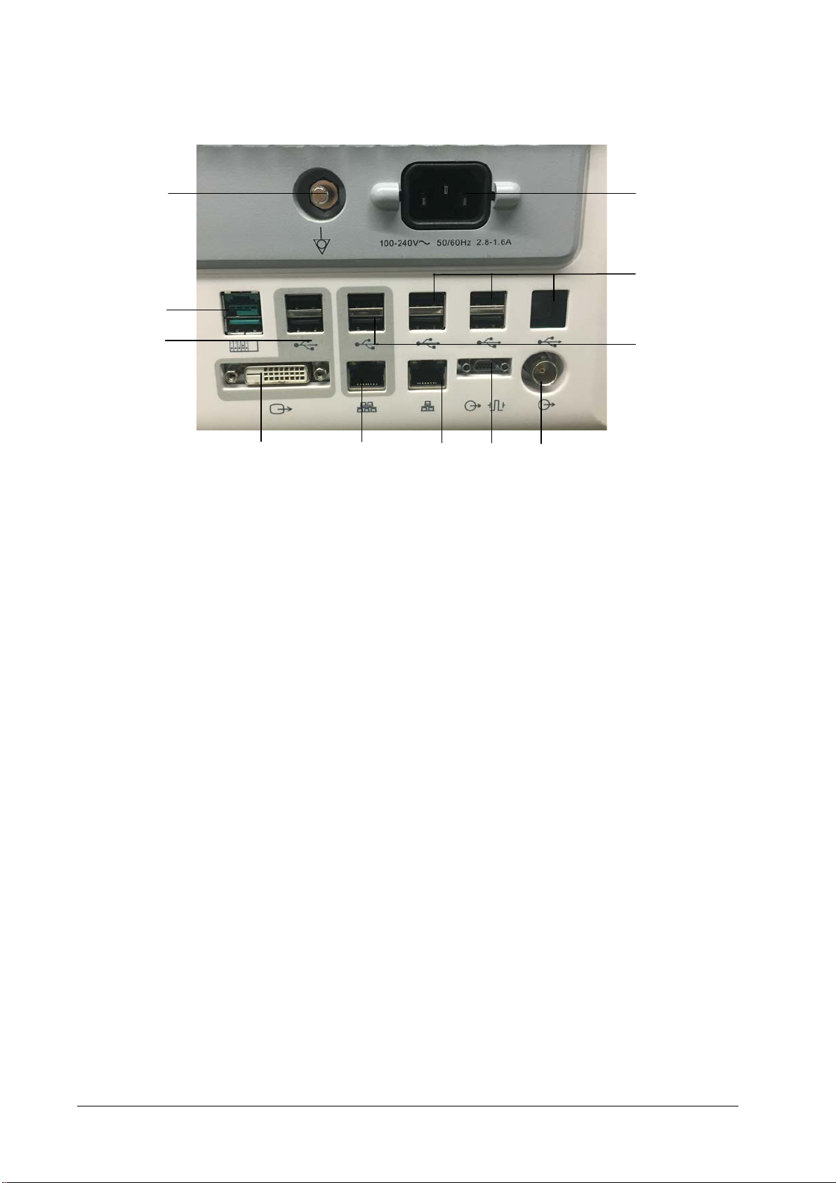
On the back of the patient monitor you will find all connectors for peripheral devices.
5 6 7 8
1. AC Power Connector: used to connect an AC power source (100 to 240 VAC, 50/60Hz).
2. Equipotential Terminal: used to connect the equipotential terminal of other equipment, eliminating potential
difference between different pieces of equipment.
3. SMR Connector:
and operate the SMR.
4. Video Output: It is a DVI-D connector used to connect a secondary display.
5. iView Network Connector: It is a RJ45 connector that connects iView system to external network.
6. Network Connector: It is a RJ45 connector used to connect an ethernet network or a PC.
7. Analog Output and Defibrillator Connector: It is a Micro-D connector used to output analog signals and
defibrillator synchronization signals.
8. Auxilliary Output Connector: It is a BNC connector used to output nurse call signals.
9. Secondary USB Connector: used to connect the mouse and keyboard of the secondary display.
10. Special USB Connectors: used for iView maintenance and data transfer.
11. General USB Connector: used to connect any USB-compatible peripheral device.
Powered USB connector which is used with the special powered USB cable necessary to connect
2-2 Passport 17m Service Manual
Page 15
2.3 Main Unit
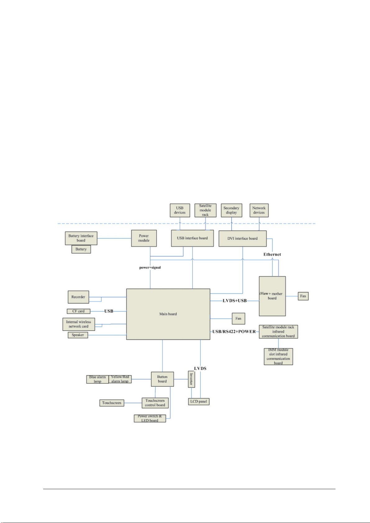
The patient monitor consists of:
Input system: button board, knob, touchscreen, power switch and LED board
Output system: LCD panel, alarm LED board, recorder, speaker
Processing and communications system: main board, iView assembly, integral module rack
Power management system: battery, battery interface board, power module
Equipment interface system: USB interface board, DVI interface board, CF card assembly and internal wireless
network card.
Additionally, the patient monitor can also support a satellite module rack (SMR), parameter modules, BeneLink
module, mouse, keyboard, etc.
The following diagram illustrates the structure of the patient monitor.
Passport 17m Service Manual 2-3
Page 16
2.3.1 Input System
Button board
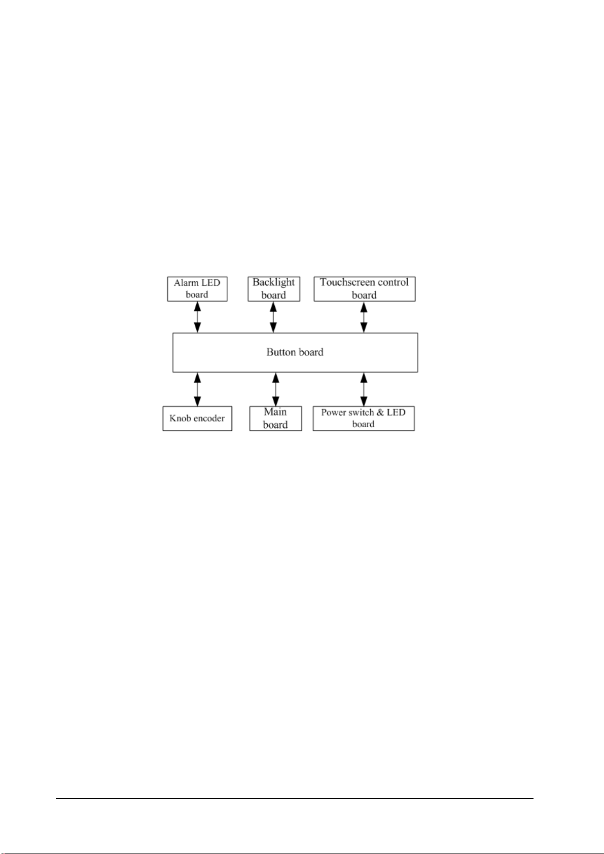
The button board, located at the lower part of the monitor’s front panel, contains 6 keys and provides connections for
the following components to the main board:
Knob
Power switch & LED board
Touchscreen control board
Backlight board
Alarm LED board
The following diagram shows the button board connections.
Knob
The knob can be pressed, or rotated both clockwise and counter-clockwise. It is connected to the button board.
Touchscreen
The touchscreen enables touch operations and can be calibrated. It is connected to the touchscreen control board
and main board.
Power switch & LED Board
The power switch & LED board controls the power supply for the main unit. It has three LEDs, which respectively
indicate the AC power status, battery status and monitor power on/off status. It is connected to the button board.
2-4 Passport 17m Service Manual
Page 17
2.3.2 Output System
LCD
The patient monitor utilizes a high-resolution LCD. The LCD is connected to the main board. Signals and power supply
of the backlight board are transferred by the button board.
Alarm Lamp
The patient monitor has two alarm lamps integrated in the alarm lamp board. Alarm lamps light either red or yellow.
The alarm lamp signals are transferred by the button board and are directly controlled by the main board.
Recorder
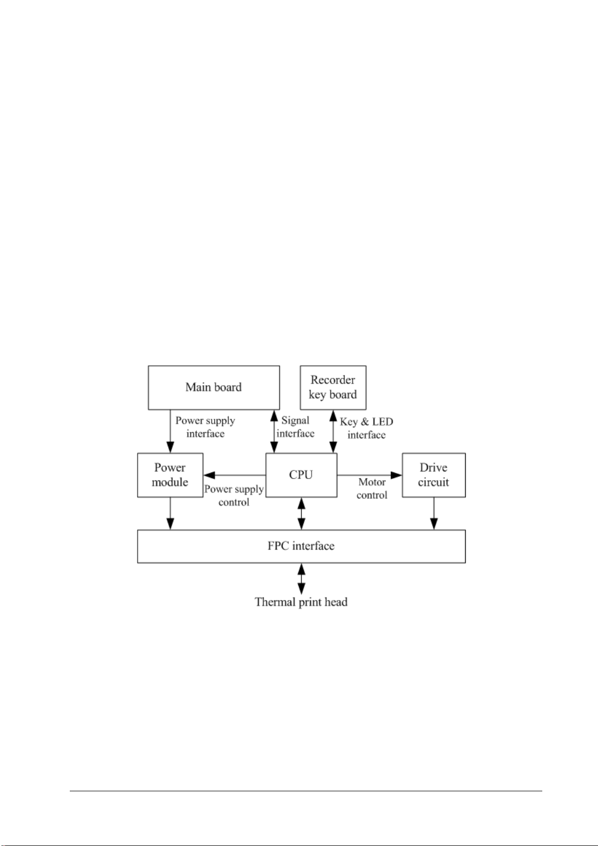
The recorder receives data coming from the main board and transmits it to the thermal printhead for printing. The
recorder has a hardkey (start/stop recordings) and a green LED on its front. It is connected to the main board.
The following diagram shows its operating principle.
Passport 17m Service Manual 2-5
Page 18

Module Description
Power interface Introduces a DC from the main board.
Power module
CPU Controls all the communications between modules.
Signal interface Controls all the communications between the main board and the recorder CPU.
Motor drive circuit Receives the control signals from the CPU and then forwards them to the stepper motors.
Button & LED board The button board and the LED board are controlled directly by the CPU board.
Converts the input A/C power into appropriate D/C voltages which power individual
modules.
Speaker
The speaker provides sound for alarms, key strokes, heart beats and pulse, and allows PITCH TONE and multi-level tone
modulation. It is connected with the main board and is directly driven by the main board.
2-6 Passport 17m Service Manual
Page 19
2.3.3 Processing and Communications System
Main Board
The main board is the heart of the patient monitor. It implements a series of tasks including input & output control,
data storage and processing, display processing, system control, communication management, printing management
and alarming, etc.
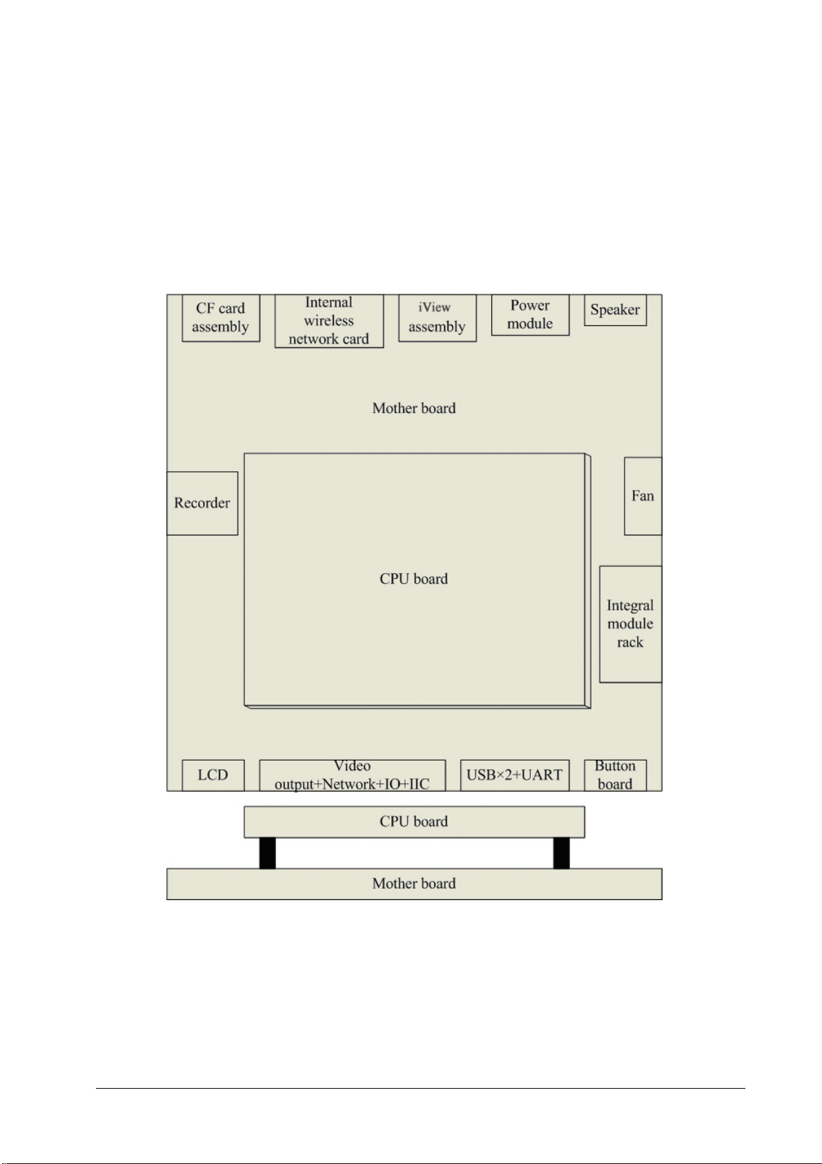
The main board is comprised of the CPU board and mother board. The following diagram shows interfaces to other
components.
The CPU board consists of the CPU, FLASH, memory, realtime clock, EEPROM, etc. It interfaces to the mother board
only, which then provides interfaces to all other external devices.
Passport 17m Service Manual 2-7
Page 20

The mother board controls all connections and communications with other components and provides the following
interfaces:
LCD port: connects a built-in display.
Video output+network+IO+IIC: connects the digital video interface board.
USB×2+UART: connects the USB interface board.
Button board port: connects the button board.
Integral module rack port: connects integral module rack communication board.
Fan port: connects the fan.
Speaker port: connects the speaker.
Power module port: connects the power module.
iView port: located at the back of the mother board for connecting the iView components.
CF port: connects the CF card assembly.
Recorder port: connects the recorder.
Internal wireless network card port: connects the internal wireless network card
iView System
iView sytem includes iView mother board, computer board, hard disk, etc. iView system connects to the main control
board, DVI interface board and USB interface board. The iView system transmits the network signal to the host
network interface through DVI interface board.
Integral Module Rack
The patient monitor has two kinds of integral module racks: 2-slot and 5-slot. The control board includes a NIOS II
FPGA. It implements protocol conversion and infrared communication between the main unit and the parameter
modules.
The module rack communication board can be a 2-slot type or a 3-slot type. The 3-slot communication board
communicates with the main board directly. The 2-slot communication board is connected to and is controlled by the
3-slot communication board. The 3-slot communication board has the function of communication control. The 2-slot
communication board consists of the infrared circuit and module power circuit. The RS422 drive circuit is located on
the 3-slot communication board.
2-8 Passport 17m Service Manual
Page 21
2.3.4 Power Management System
Battery
The patient monitor uses two rechargeable lithium-ion batteries (11.1 V, 4500 mAh). The battery compartment door is
located at the bottom of the patient monitor. The battery power is introduced to the power module via the battery
interface board, and then processed and distributed to each component by the power module.
NOTE
Two batteries must be used simultaneously when the patient monitor operates on battery power.
Battery Interface Board
The battery interface board connects batteries to the power module, enabling charging and discharging between the
batteries and the power board.
Power Module
The power module is located at the back of the patient monitor. The main part of the power module is the power
board, which contains 4 PCBs: charging & power management board, voltage drop DC inverter, voltage rise and drop
DC inverter, and voltage drop 5 V CIS power board.
The power module transforms the input power into DC and supplies each component of the patient monitor. The
input power comes from either the batteries or an AC source. The patient monitor will run power from the AC source
whenever an AC source is available. If the AC source is not available, the patient monitor will automatically switch to
battery power. This does not affect the monitor’s operating status.
Power module has an AC input socket at its backside, and a socket at its front provides 4 connections to the batteries,
main board, iView components and USB interface board respectively. The power module protects itself and the
patient monitor by switching off AC input or DC output in case of overcurrent, short circuit and overvoltage.The
power module provides 4 DC outputs:
Outputs Description
+3.3 VDC Goes to the LCD, mother board, CPU board, DVI interface board and integral module rack.
+5.0 VDC Goes to the DVI interface board, recorder, CF storage card board and USB interface board.
+5.0 VDC CIS Goes to the iView assembly.
+12 VDC
Goes to the recorder, LCD inverter, integral module rack, parameter modules and USB
interface board.
Passport 17m Service Manual 2-9
Page 22
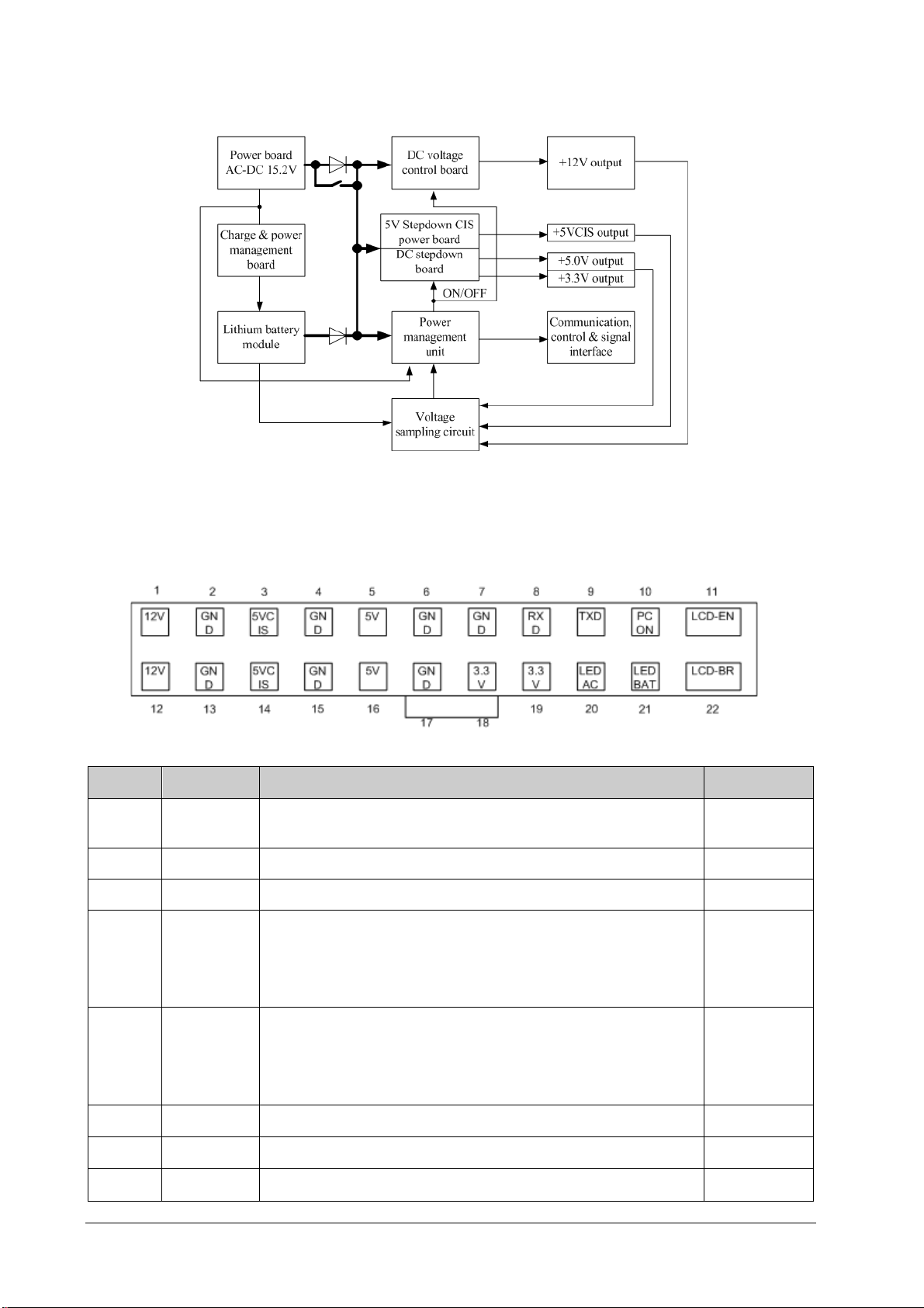
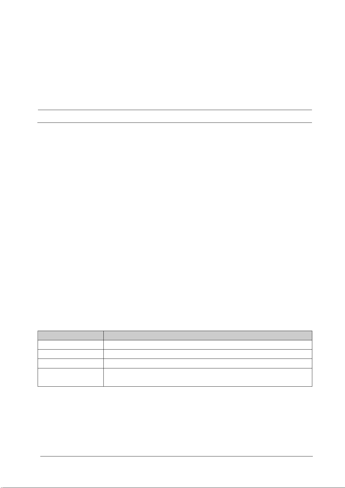
The systematic principle diagram of the power module is as follows:
The following diagram shows the pins of the power module socket (excluding the pins of the battery power socket.
On power board, pin 1 has a triangle symbol):
Pin ID Marking Description Cable color
2, 4, 6, 7,
13, 15, 17
8 RXD Receives serial communications (from the main board ). Purple
9 TXD Sends serial communications (to the main board). Brown
10 PCON
11 LCD-EN
12, 1 12 V The positive end of the 12 VDC coming from the power board. Yel low
14, 3 5 V CIS The positive end of the 5 VDC CIS coming from the power board. Purple
GND The output grounding terminal of the power board. Black
Power on/off control signal. A TTL pulse signal inputted from the back
board. Every time the power on/off switch is pressed (pulse of falling
edge), a switch between power “on” and “off” happens. The pulse duration
is no less than 0.1 s for power-on and no less than 2 s for power off.
Back light on/off control signal. The main board sends a backlight on/off
control signal to the power board through the serial interface. The power
board processes the received signal and then outputs a high or low signal
depending on the received signal.
Blue
Green
16, 5 5 V The positive end of the 5 VDC coming from the power board. Red
2-10 Passport 17m Service Manual
Page 23
Pin ID Marking Description Cable color
18, 19 3.3 V The positive end of the 3.3 VDC coming from the power board. Orange
20 LED- AC AC power status indication signal White
21 LED- BAT Battery status indication signal. Grey
22 LCD-BR Backlight brightness control voltage. Brown
2.3.5 Equipment Interface System
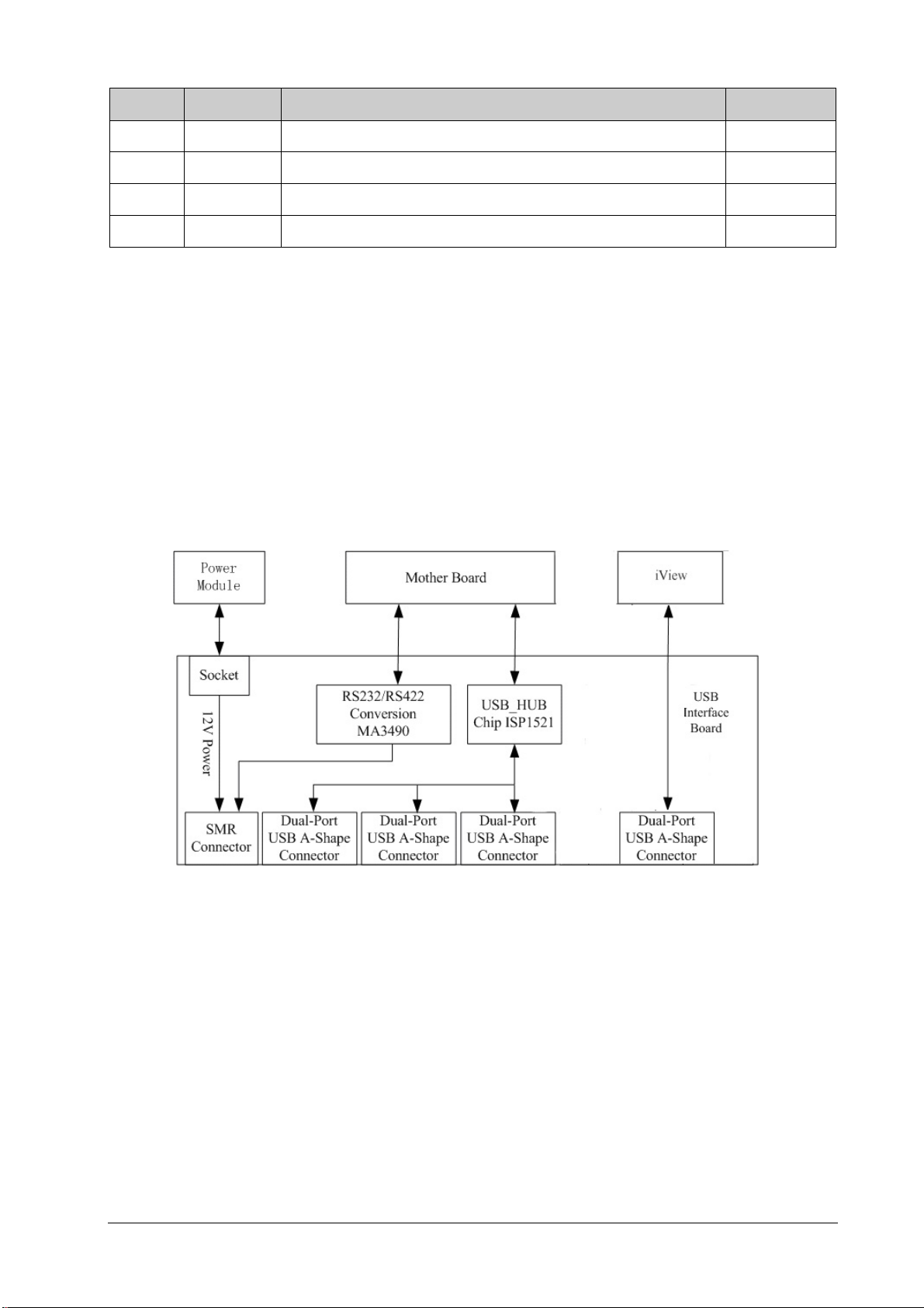
USB Interface Board
The USB interface board is compatible with such USB interfaces as USB2.0, USB1.1 and USB1.0. It is connected with the
main board and the power module. It receives USB differential signals coming from the main board and then
distributes them to a maximum of six USB interfaces via two ISP1521 chips. The USB interface board of the iView
system directly connects to two USB interfaces (on the USB board) of the host. The UART signal output by the main
board is converted into RS422 signal by the USB interface board. The USB interface board receives 5 VDC and 12 VDC
inputs from the power module, of which the 5 VDC goes to the USB interface board and the 12 VDC outputted to the
SMR connector through a fuse.
Passport 17m Service Manual 2-11
Page 24
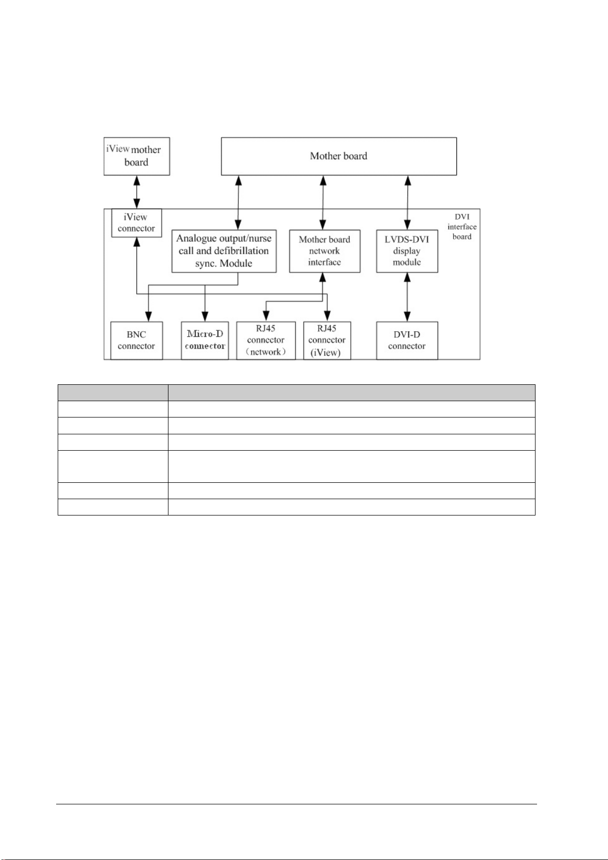
DVI Interface Board
The DVI interface board is connected with the mother board and the iView mother board. The following diagram
shows its interfaces to other components.
Interface Description
iView Connector Connects the iView mother board.
BNC connector Outputs nurse call signals.
Micro-D connector Outputs analog signals and defibrillator synchronization signals.
RJ 45 connector
(network)
RJ 45 connector (iView) A standard RJ45 connector for connecting a iView network.
DVI-D connector Connects a secondary display.
A standard RJ45 connector, providing 10/100 BASE-TX Ethernet communications channels. It
connects an Ethernet network or a PC.
CF Card assembly
The CF assembly serves the non-volatile CF storage card which is used for data storage and transfer. It is connected
with the mother board.
Internal wireless network card
The internal wireless network card connects with the mother board. User can set network type as LAN or WLAN
through user interface and can set the internal wireless network card through PC.
2-12 Passport 17m Service Manual
Page 25

2.4 Parameter Module
Each parameter module consists of the module infrared communication board, module power board, module button
board, parameter board, etc.
2.4.1 Module Infrared Communication Board
The module infrared communication board allows a short delay when powering up the module and adopts FPGA to
enable infrared communications between the module and the module rack. An ID is integrated into the module
infrared communication board. When a module is inserted in the module rack, the ID is automatically sent to the
module rack.
2.4.2 Module Power Board
Some modules have no power board. There are two kinds of module power board:
1. Isolated power board: converts the 12 VDC into a 12 V isolated DC and a 5 V isolated DC.
2. Non-isolated power board: converts the 12 VDC into a 5 VDC.
2.4.3 Parameter Board
The parameter board is a parameter measurement component.
Passport 17m Service Manual 2-13
Page 26
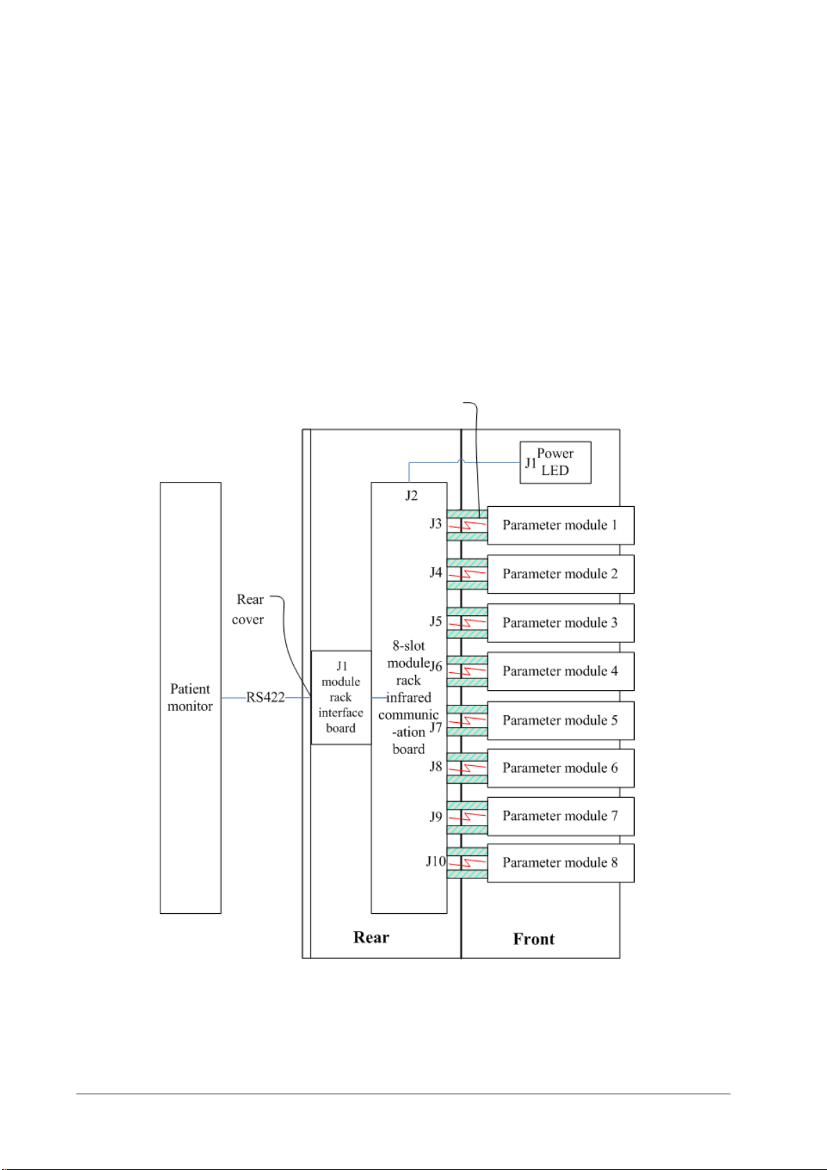
2.5 Satellite Module Rack
The satellite module rack (SMR) is independent of the patient monitor, provides 8 slots for mounting parameter
modules. It has the following features:
It allows a parameter module to be plugged and unplugged with the patient monitor on. This allows function
extension and patient transfer.
The SMR receives 12 VDC through a powered USB cable coming from the 17m monitor. It then supplies power to
each parameter module via the contact screw.
It accomplishes communications protocol conversions between the patient monitor and each parameter module,
provides infrared communications for parameter modules, and is responsible for detecting infrared
communications malfunction for each parameter module.
The following diagram shows the structure of the SMR.
2-14 Passport 17m Service Manual
Page 27
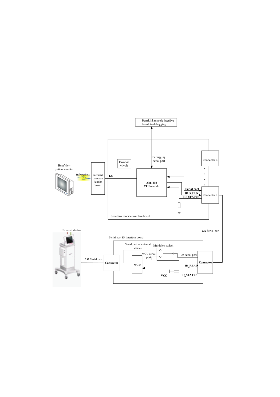
2.6 BeneLink Module
The BeneLink module allows the information (patient data, alarms, etc.) from the external device to be displayed,
saved, recorded, printed, or calculated through the patient monitor. If the patient monitor is connected with the CMS
or gateway, information from the external device can also be transmitted to the CMS or gateway. The BeneLink
module connects with the external device through an ID module, which enables the information transmission
between the BeneLink module and the external device. The BeneLink module can be connected to many external
devices such as anesthesia machines and ventilators.
The following diagram shows the structure of the BeneLink module:
Passport 17m Service Manual 2-15
Page 28

FOR YOUR NOTES
2-16 Passport 17m Service Manual
Page 29
3 Testing and Maintenance
3.1 Introduction
To ensure the patient monitor always functions properly, qualified service personnel should perform regular
inspections, maintenance and tests. This chapter provides a checklist of the testing procedures for the patient monitor
with recommended test equipment and inspection schedule.
The testing procedures provided in this chapter are intended to verify that the patient monitor meets the
performance specifications. If the patient monitor or a module fails to perform as specified in any test, repairs or
replacement must be done to correct the problem. If the problem persists, contact Mindray Technical Support
Department.
CAUTION
All tests should be performed by qualified service personnel only.
Care should be taken when changing the settings in [User Maintenance>>] and [Factory Maintenance>>]
menus to avoid loss of data.
Service personnel should possess a working knowledge of the test equipment and make sure that test
tools and cables are applicable.
3.2 Preventative Maintenance
Preventative maintenance refers specifically to actions taken to prevent inaccurate results in the equipment. The
following sections provide a list of recommended preventative maintenance procedures and their recommended
frequencies.
3.2.1 Preventative Maintenance Frequency
Check/Maintenance Item Frequency
NIBP test
Sidestream and
Microstream CO
and calibration
AG tests
tests
2
Pressure check
Leak test
Leak test
Performance test
Calibration
Performance test
Calibration
1. If the user suspects that the measurement is
incorrect.
2. Following any repairs or replacement of relevant
module.
3. Once a year.
4. AG leak test should be performed before AG
measurement.
Passport 17m Service Manual 3-1
Page 30

3.2.2 CO
3.2.2.1 CO
Tests
2
Leak test
2
Follow this procedure to perform the test:
1. Plug the module into the module rack.
2. Wait until CO
warmup is finished and then completely block the gas inlet of the module or watertrap (you may
2
use a pneumatic plug or your finger to manually occlude the port). The sidestream and microstream CO
modules will behave as follows:
Sidestream: The alarm message [CO
inlet for another 60 s. Select [Main Menu] → [Maintenance >>] → [User Maintenance >>] → enter the
required password → [Module Maintenance >>] → [Maintain CO
the flow rate is less than 10ml/min. The module does not leak if current flow rate is less than 10ml/min and
the alarm message does not disappear.
Microstream: The alarm message [CO
inlet for another 30s. If alarm message [CO
does not leak.
3.2.2.2 CO
Accuracy Test
2
Tools required:
A gas cylinder with 5±0.03% CO
with:
CO
a/c ≤ 0.01 (where a = absolute gas concentration accuracy, c = gas concentration)
concentration 3% - 7%
2
2
FilterLine Err] is displayed on the screen after 3 seconds. Block the gas
2
>>] → [Calibrate CO2 >>], and verify
2
Purging] is displayed on the screen after a short time. Block the gas
2
FilterLine Occluded] is shown, it indicates that the module
2
, 21.0% O2 and balance gas N2 (P/N 0075-00-0033-01), or a steel gas cylinder
2
balance gas N
2
T-shape connector
Tubing
Follow this procedure to perform the test:
1. Connect the CO
2. Wait until the CO
module.
2
module warmup is finished. Check the airway for leak.
2
3. Select [Main Menu] → [Maintenance >>] → [User Maintenance>>] → enter the required password →
[Module Maintenance>>] → [Maintain CO
>>] → [Calibrate CO2>>].
2
3-2 Passport 17m Service Manual
Page 31
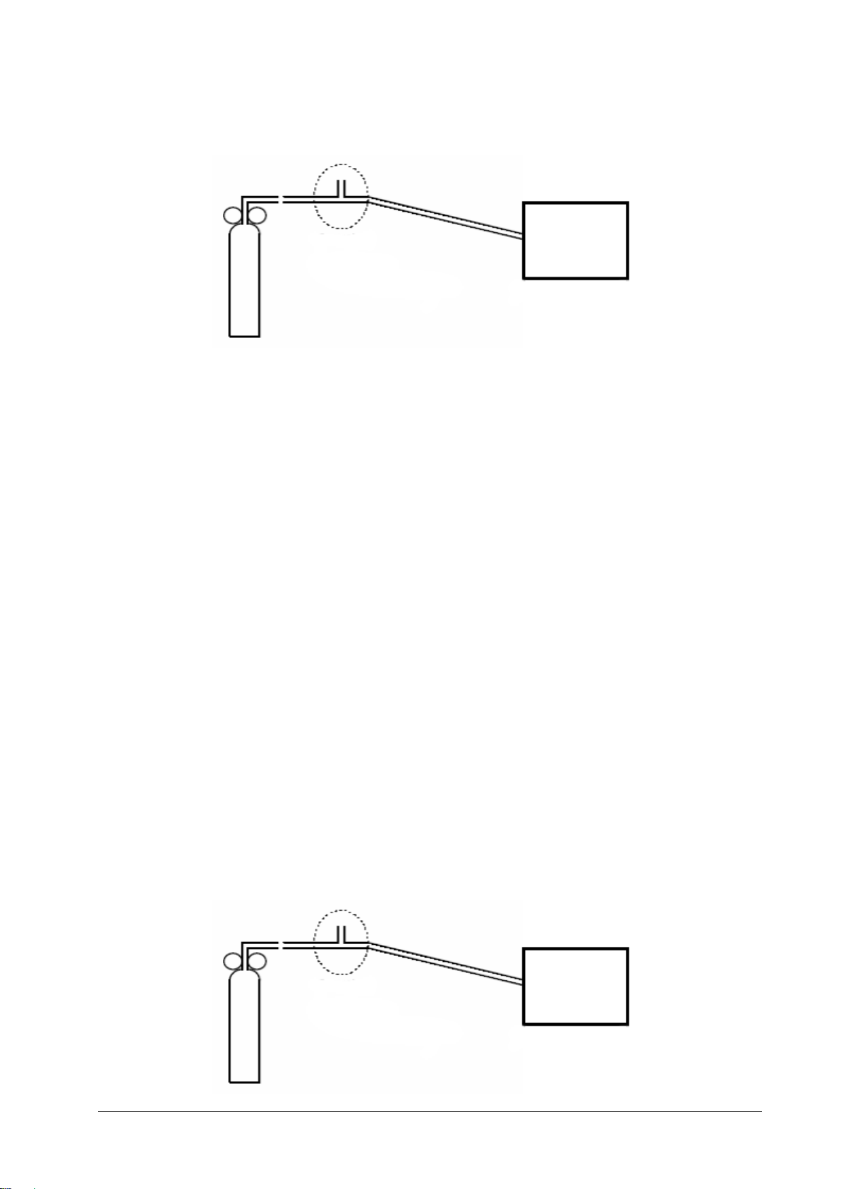
4. Connect the test system as follows:
Valve
Gas cylinder
5. Open the valve to flow CO
6. Verify the realtime CO
3.2.2.3 CO
Calibration
2
Tools required:
A gas cylinder with 5±0.03% CO
CO
a/c ≤ 0.01 (where a = absolute gas concentration accuracy, c = gas concentration)
concentration 3% - 7%
2
Open to the air
Tubing
T-shape connector
and make sure that there is flow sufficient to vent to atmosphere.
2
value is within 5.0±0.3% in the [Calibrate CO
2
, 21.0% O2 and balance gas N2 (P/N 0075-00-0033-01), or a gas cylinder with:
2
Monitor
] menu.
2
balance gas N
2
T-shape connector
Tubing
Follow this procedure to perform a calibration:
1. Make sure that the sidestream or microstream CO
module has been warmed up.
2
2. Check the airway for leaks.
3. Select [Main Menu] → [Maintenance >>] → [User Maintenance >>] → enter the required password →
[Module Maintenance>>] → [Maintain CO
4. In the [Calibrate CO
] menu, select [Zero].
2
>>] → [Calibrate CO2 >>].
2
5. After the zero calibration is finished successfully, connect the equipment as follows:
Open to the air
Valve
Tubing
Monitor
T-shape connector
Gas cylinder
Passport 17m Service Manual 3-3
Page 32

6. Open the valve to flow CO
7. In the [Calibrate CO
8. In the [Calibrate CO
concentration becomes stable, select [Calibrate CO
and make sure that there is flow sufficient to vent to atmosphere.
2
] menu, enter the CO2 concentration in the [CO2] field.
2
] menu, the measured CO2 concentration is displayed. After the measured CO2
2
] to calibrate the CO2 module.
2
If the calibration is completed successfully, the message [Calibration Completed!] is displayed in the [Calibrate CO
menu. If the calibration failed, the message “Calibration Failed!” is displayed. If the initial calibration fails, perform a
second calibration. If that attempt fails, contact Mindray Technical Support for assistance.
3.2.3 AG Tests
3.2.3.1 Leak Test
Follow this procedure to perform the test:
1. Plug the AG module into the module rack.
2. Wait until the AG module warmup is finished and then completely block the gas inlet of the AG module (you may
use a pneumatic plug or your finger to manually occlude the port). An alarm message [AG Airway Occluded] will
appear on the screen.
3. Block the gas inlet for another 30 s. Select [Main menu] → [Maintenance >>] → [User Maintenance >>] →
enter the required password → [Module Maintenance >>] → [Calibrate AG >>], and verify the current flow
rate is less than 10 ml/min.
]
2
If the alarm message does not disappear, it indicates that the module does not leak.
If the flow rate is less than 10ml/min and the alarm message [AG Airway Occluded] does not disappear, it indicates
that the module does not leak. If the alarm message disappears, or the flow rate is greater than or equal to 10ml/min,
it indicates that the module leaks. If the problem remains, contact your service personnel for assistance.
3.2.3.2 Accuracy Test
Tools required:
A supply of medical grade 100% O
P/N: 0075-00-0048-01 and flow regulator P/N: 0119-00-0235). Gas concentration should meet the following
requirements:
AA ≥ 1.5%, CO
≥ 1.5%, N2O ≥ 40%, O2 ≥ 40%, of which AA represents an anesthetic agent. a/c ≤ 0.01 (a is the gas
2
absolute concentration accuracy; c is the gas concentration)
T-shape connector
Tubing
Follow this procedure to perform the test:
and an anesthetic calibration gas (4% Desflurane, 6% CO2, 45% N2O, Bal O2,
2
1. Plug the AG module into the module rack.
2. Wait at least 10 min and then perform a leak test to make sure the airway has no leak.
3. Check if the fan inside the AG module works properly.
3-4 Passport 17m Service Manual
Page 33
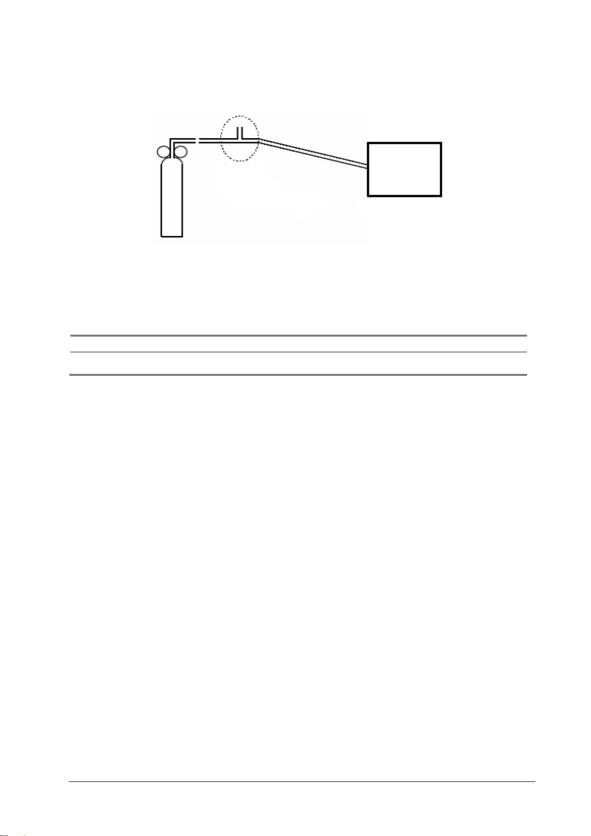
Monitor
Gas cylinder
Open to the air
Relief valve
Tubing
4. Connect the test system as follows:
5. Open the relief valve and vent a standard gas and make sure that there is an excess gas flow through the T-shape
connector to air.
6. Verify the concentration of each composition meets the specification stated in the Operator's Manual.
WARNING
When performing AG accuracy test and AG calibration, be sure to dispose of exhaust gas properly.
3.2.3.3 Calibration
Tools required:
Gas cylinder, Mindray P/N 0075-00-0048-01 and flow regulator P/N0119-00-0235 with an anesthetic calibration
gas (4% Desflurane, 6% CO
concentration should meet the following requirements: AA ≥ 1.5%, CO
, 45% N2O, Bal O2, P/N: 0075-00-0048-01 and flow regulator P/N: 0119-00-0235). Gas
2
≥ 1.5%, N2O ≥ 40%, O2 ≥ 40%, of which
2
AA represents an anesthetic agent. a/c ≤ 0.01 (a is the gas absolute concentration accuracy; c is the gas
concentration).For 100% O
calibration, a gas cylinder with 100% O2 is used and the O2 concentration is not less
2
than 99%.
T-shape connector
Tubing
Follow this procedure to perform a calibration:
1. Select [Main Menu] → [Maintenance >>] → [User Maintenance >>] → enter the required password →
[Calibrate AG >>].
2. Check the airway and make sure that there are no occlusions or leaks.
Vent the sampling tubing to the air and check if the [Current FlowRate] and [Set FlowRate] are
approximately the same. If the deviation is great, it indicates that there is an occlusion in the tubing. Check
the tubing for an occlusion.
Perform a leak test to make sure that the airway has no leak.
Passport 17m Service Manual 3-5
Page 34
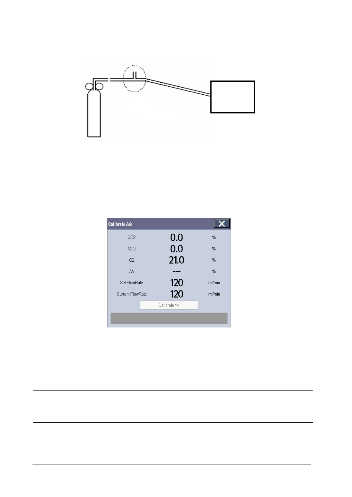
M
Gas cylinder
Open to the air
Relief valve
Tubing
Connect the test system as follows:
onitor
4. Open the relief valve and vent an anesthetic calibration gas or gas mixture and make sure that there is an excess
gas flow through the T-shape connector to air.
5. In the [Calibrate AG] menu, the concentration and flowrate of each measured gas are displayed.
If the difference between the measured gas concentration and the actual one is within tolerance, a
calibration is not needed.
If the difference is not within tolerance, a calibration should be performed. Select [Calibrate >>] to enter the
calibrate menu.
6. Enter the vented gas concentration. If you use only one gas for calibration, set other gases’ concentration to 0.
7. Select [Start] to start a calibration.
8. If the calibration is finished successfully, the message [Calibration Completed!] is displayed. If the calibration
failed, the message [Calibration Failed!] is displayed. Perform another calibration.
CAUTION
Calibrate the O
properly.
3-6 Passport 17m Service Manual
module, if it has been transported for long distance or if you suspect it does not work
2
Page 35

3.3 Performance Tests
Performance test are designed to ensure that measurement results are accurate. The following sections provide a list
of performance and accuracy tests and their recommended frequencies.
3.3.1 Performance Test Frequencies
Check/Maintenance Item Frequency
Visual inspection 1. When first installed or reinstalled.
Performance test
ECG test
Verification
Resp performance test
SpO2 test
1. If the user suspects that the measurement is incorrect.
2. Following any repairs or replacement of relevant module.
3. At least once every two years. At least once a year is
recommended for NIBP, CO
4. AG leak test should be performed before AG measurement.
and AG.
2
NIBP test
Temp test
IBP test
C.O. test
CO2 tests and
calibration
AG tests
BIS test
Pressure check
Leak test
Performance test
Pressure calibration
Leak test
Performance test
Calibration
Leak test
Performance test
Calibration
RM test
CCO/SvO2 test
ScvO2 test
Nurse call relay performance test
Analog output performance test
BeneLink module check
Passport 17m Service Manual 3-7
Interconnecting function
Output calibration
If the user suspects that the nurse call or analog output does not
work correctly.
1. When first installed.
2. Following any repair or replacement of the external device.
Page 36

3.3.2 Visual Inspection
Inspect the equipment for obvious signs of damage. Follow these guidelines when inspecting the equipment:
Carefully inspect the case, display screen, buttons and knob for obvious signs of damage.
Inspect the SMR and parameter modules for obvious signs of damage.
Inspect the power cord, wall-mount bracket and module accessories for obvious signs of damage.
Inspect all external connections for loose connectors, bent pins or frayed cables.
Inspect all connectors on the equipment for loose connectors or bent pins.
Make sure that safety labels and data plates on the equipment are clearly legible.
After visual inspection, replace any damaged equipment parts or accessories.
3.3.3 ECG Tests
3.3.3.1 ECG Performance Test
Tool required:
Fluke Medsim 300B patient simulator or equivalent equipment
Follow this procedure to perform the test:
1. Connect the patient simulator with the ECG module using an ECG cable.
2. Set the patient simulator as follows: ECG sinus rhythm, HR=80 bpm with the amplitude as 1mV.
3. Check the ECG waves are displayed correctly without noise and the displayed HR value is within 80 ± 1 bpm. If
the value is not within 80 +/-1 then contact Mindray Technical Support
4. Disconnect each of the leads in turn and observe the corresponding lead off message displayed on the screen.
5. Set the output of the simulator to deliver a paced signal and set [Paced] to [Yes] on the monitor. Check the pace
pulse marks on the monitor screen.
3-8 Passport 17m Service Manual
Page 37

3.3.3.2 ECG Verification
Tool required:
Vernier caliper
Follow this procedure to perform verification:
1. Select the ECG parameter window or waveform area → [Filter]→ [Diagnostic].
2. Select [Main Menu] → [Maintenance >>] → [User Maintenance >>] → enter the required password →
[Module Maintenance>>].
3. Select [Calibrate ECG]. A square wave appears on the screen and the message [ECG Calibrating] is displayed.
4. Compare the amplitude of the square wave with the wave scale. The difference should be within 5%. If the
difference is not within 5% contact Mindray Technical Support.
5. After completing the verification, select [Stop Calibrating ECG].
3.3.4 Resp Performance Test
Tool required:
Fluke Medsim 300B patient simulator or equivalent equipment
Follow this procedure to perform the test:
1. Connect the patient simulator to the module using a non ESU-proof cable and set lead II as the respiration lead.
2. Configure the simulator as follows: lead II as the respiration lead, base impedance line as 1500 Ω; delta
impedance as 0.5 Ω, respiration rate as 40 rpm.
3. Verify the Resp wave is displayed without any distortion and the displayed Resp value is within 40 ± 2 rpm.
3.3.5 SpO
Test
2
Tool Required:
None.
Follow this procedure to perform the test:
1. Connect SpO
sensor to the SpO2 connector of the monitor. Set [Patient Cat.] to [Adu] and [PR Source] to SpO2
2
on the monitor.
2. Apply the SpO
3. Check the Pleth wave and PR reading on the screen and make sure that the displayed SpO
100%. If you are unable to get the SPO
4. Remove the SpO
sensor to the ring finger of a healthy person.
2
is within 95% and
2
between 95% and 100%, contact Mindray Technical Support.
2
sensor from the finger and make sure that an alarm of SpO2 Sensor Off is triggered.
2
NOTE
A functional tester cannot be used to assess the accuracy of a pulse oximeter monitor. However, it can be
used to demonstrate that a particular pulse oximeter monitor reproduces a calibration curve that has
been independently demonstrated to fulfill a particular accuracy specification.
Passport 17m Service Manual 3-9
Page 38
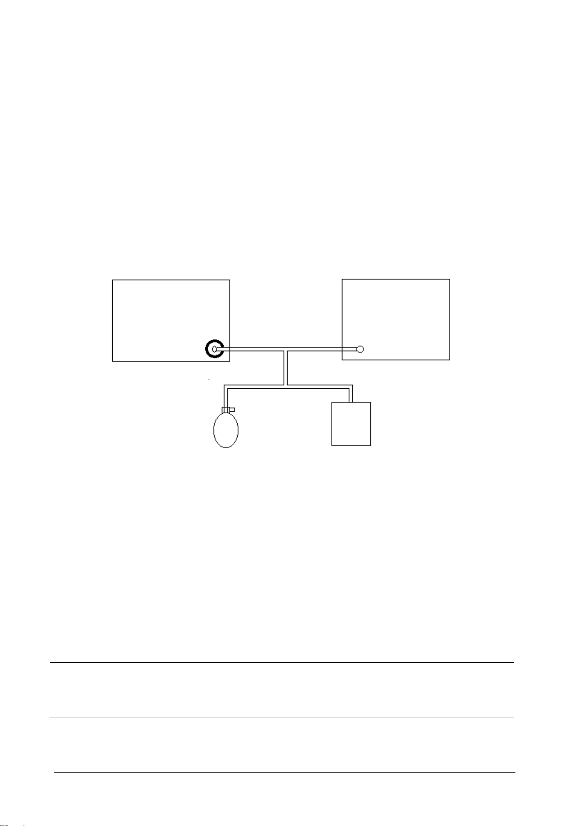
Monitor
Squeeze bulb
3.3.6 NIBP Tests
3.3.6.1 NIBP Accuracy Test
Tools required:
T-shape connector
Appropriate tubing
Squeeze bulb
Rigid Vessel with volume 500 ± 25 ml
Reference manometer (calibrated with accuracy equal to or better than 0.75 mmHg)
Follow this procedure to perform the test:
1. Connect the equipment as shown below.
Connector for NIBP cuff
Tubing
Manometer
2. Before inflation, the reading on the manometer should be zero. If not, disconnect the squeeze bulb to release any
pressure. Reconnect the squeeze bulb and verify that the pressure reading is zero.
3. Select [Main Menu] → [Maintenance >>] → [User Maintenance >>] → enter the required password →
[Module Maintenance>>] → [NIBP Accuracy Test].
4. Check the manometer values and the monitor values. Both should be 0 mmHg.
5. Raise the pressure in the rigid vessel to 50 mmHg with the squeeze bulb. Then, wait for 10 seconds until the
measured values become stable.
6. Compare the manometer values with the monitor values. The difference should be within ±3 mmHg.
7. Raise the pressure in the rigid vessel to 200 mmHg with the squeeze bulb. Then, wait for 10 seconds until the
measured values become stable and repeat step 6.
Rigid vessel
NOTE
You can use an NIBP simulator to replace the squeeze bulb and the reference manometer to perform the
test.
You can use an appropriate cylinder and a cuff instead of the rigid vessel.
3-10 Passport 17m Service Manual
Page 39
Monitor
Rigid c
3.3.6.2 NIBP Leakage Test
NOTE
You should perform the NIBP leakage test before any other NIBP test.
Tools required:
NIBP cuff for adult patient
Appropriate tubing
Rigid cylinder
Follow this procedure to perform the test:
1. Set [Patient Cat.] to [Adu].
2. Connect the NIBP cuff to the NIBP connector on the monitor.
3. Wrap the cuff around the cylinder as shown below.
ylinder
Connector for NIBP cuff
4. Select [Main Menu] → [Maintenance >>] → [User Maintenance >>] → enter the required password →
[Module Maintenance>>] → [NIBP Leakage Test]. The message [Leakage Testing…] is displayed in the NIBP
parameter area.
5. The cuff automatically deflates after 20s, which means NIBP leakage test is completed.
If no message is displayed in the NIBP parameter area, it indicates that the system does not leak. If the message
[NIBP Pneumatic Leak] is displayed, it indicates that the system may have a leak. In this case, check to make sure
the NIBP cuff, hose and connectors are not leaking and perform the test again.
You can also perform a manual leak test:
1. Perform procedures steps 1 to 4 in the NIBP Accuracy Test.
2. Raise the pressure in the rigid vessel to 250 mmHg with the squeeze bulb. Then, wait for 5 seconds to let the
measured values becoming stable.
NIBP hose
Cuff
3. Record the current pressure value, and then, record the pressure value after 60s.
4. Compare the two pressure values and make sure the difference is not greater than 6 mmHg.
Passport 17m Service Manual 3-11
Page 40

3.3.7 Temp Test
Tool required:
Resistance box (with accuracy above 0.1Ω) or equivalent in Patient Simulator
Follow this procedure to perform the test:
1. Connect the two pins of any Temp connector of a module to the two ends of the resistance box using 2 wires.
2. Set the resistance box to 1354.9Ω (corresponding temperature is 37ºC).
3. Verify that the displayed value is within 37 ± 0.1ºC. If the temperature is not within 37 ± 0.1ºC, contact Mindray
Technical Support.
4. Repeat steps 1 to 3 and verify another temperature channel.
3.3.8 IBP Tests
3.3.8.1 IBP Performance Test
Tools required:
Medsim300B patient simulator, or MPS450, or equivalent equipment
IBP adapter cable for test (P/N 009-002199-00 for Medsim 300B, P/N 009-002198-00, for MPS450)
Follow this procedure to perform the test:
1. Connect the patient simulator to the monitor’s IBP connector.
2. Verify the patient simulator output to the IBP channel is zero.
3. Select IBP Zero in the IBP setup menu to make a zero calibration.
4. Configure the patient simulator as P (static) = 200 mmHg.
5. The displayed value should be within 200 ± 4 mmHg. If the error is beyond ±4 mmHg, return the IBP module to
the factory for repair.
6. Set the patient simulator output to 120/80 mmHg ART signal and 120/0 mmHg LV signal to the IBP channel and
check that the IBP wave is displayed correctly.
7. Repeat the steps above for all the IBP channels.
3-12 Passport 17m Service Manual
Page 41

3.3.8.2 IBP Pressure Calibration
Method 1:
Tools required:
Medsim300B Patient simulator, MPS450, or other equivalent device
Dedicated IBP adapter cable (300B, P/N 00-002199-00) (use P/N 00-002198-00, if the simulator is MPS450)
Follow this procedure to perform the test:
1. Connect the patient simulator to the pressure connector on the module.
2. Set the patient simulator to 0 pressure for the desired IBP channel.
3. Press the Zero Key on the module to perform a zero calibration.
4. Configure the patient simulator as P (static) = 200 mmHg.
5. Select [Main Menu] → [Maintenance >>] → [User Maintenance >>] → [Cal. IBP Press. >>]. In the [Cal. IBP
Press.] menu, set the calibration value to 200 mmHg.
6. Select the [Calibrate] button next to the desired IBP channel to start a calibration.
7. If the calibration is completed successfully, the message [Calibration Completed!] will be displayed. Otherwise,
a corresponding message will be displayed.
Method 2:
Tools required:
Standard sphygmomanometer
Squeeze bulb
Tubing
T-shape connector
To perform a calibration:
1. Connect the 3-way stopcock, the sphygmomanometer and the squeeze bulb through a T-shape connector, as
shown below.
2. Zero the transducer. Then open the stopcock to the sphygmomanometer.
3. Press the Main menu button on the equipment’s front panel. Select [Maintenance>>] → [User Maintenance >>]
→ enter the required password → [Cal. IBP Press. >>]. Then configure IBP calibration value.
Passport 17m Service Manual 3-13
Page 42
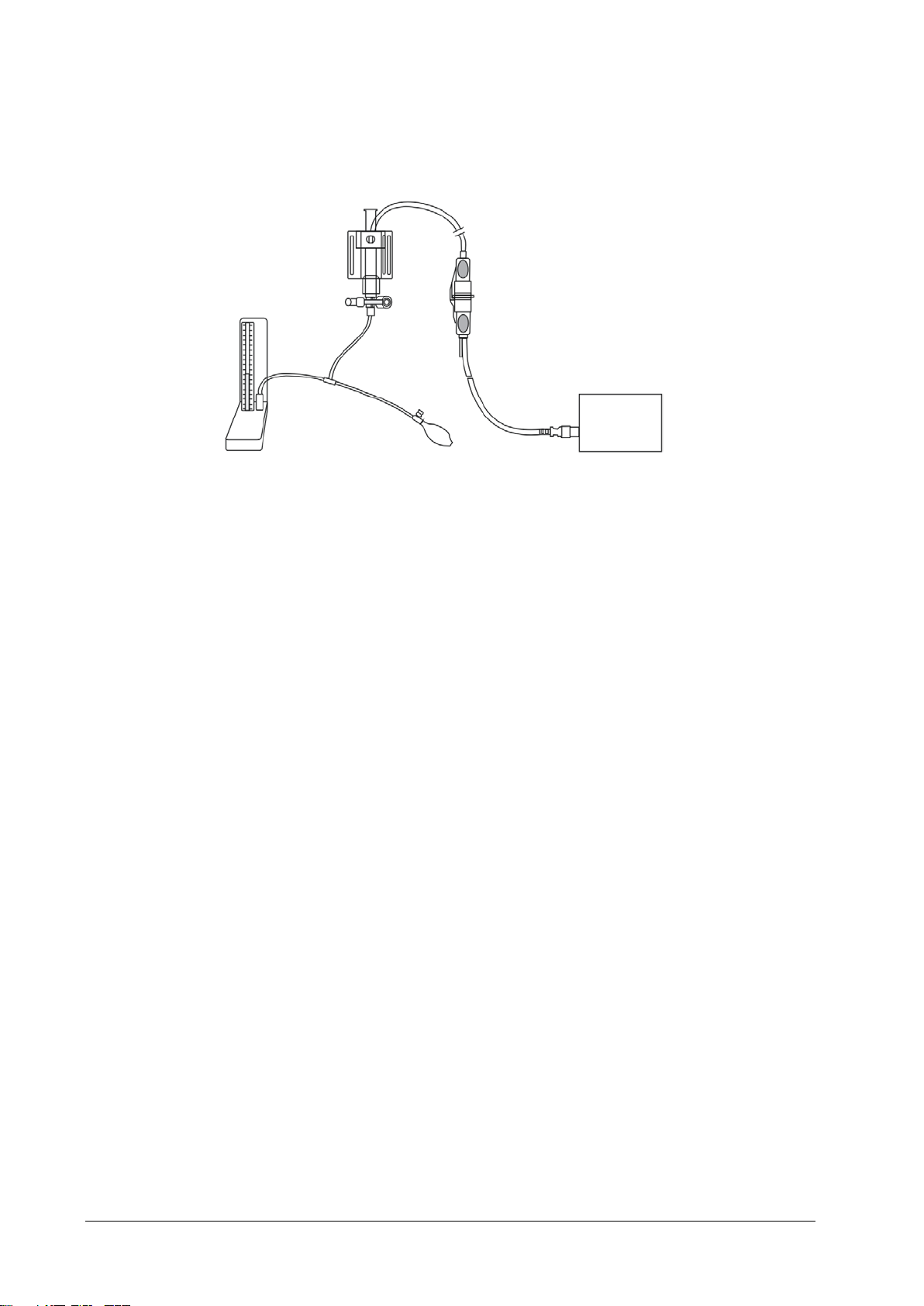
Sphygmomanometer
T
stopcock
transducer
Pressure adapter cable
IBP Module
4. Inflate using the squeeze bulb until the reading of sphygmomanometer approximates the preset calibration
value.
Pressure
3-way
-shape connector
5. Adjust the calibration value in the [Cal. IBP Press.] menu until it is equal to the reading on the
sphygmomanometer.
6. Select the [Calibrate] button to start a calibration
7. The message [Calibration Completed!] is displayed after a successful calibration. If the calibration failed, the
prompt [Calibration Failed!] will be displayed.
3.3.9 C.O. Test
Tools required:
Medsim300B Patient simulator
C.O. adapter box
1. Connect the patient simulator to the C.O. module using a C.O. main cable.
2. Set the blood temperature (BT) to 37ºC on the patient simulator and check the temperature value is 37 ± 0.1ºC.
3. Set [Auto IT] to [Off] and adjust [IT] to 24ºC. Select [C.O. Measure] to enter the C.O. measurement window and
4. Set the injectate temperature to 24ºC and the C.O. to 5L/min on the C.O. simulator. Select [Start] in the C.O.
5. Check the C.O. value is 5±0.25L/min.
3.3.10 CO
See section 3.2.2 CO2 Tests.
Follow this procedure to perform the test:
set [Comp. Const.] to 0.595.
measurement window to start C.O. measurements and after 3-10 seconds press the run key on the simulator.
Tests
2
3-14 Passport 17m Service Manual
Page 43
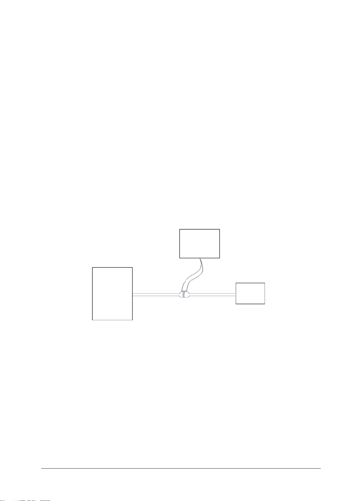
Ventilator
Artificial lung
Monitor
Flow
3.3.11 AG Tests
See section 3.2.3 AG Tests.
3.3.12 BIS Test
Tools required:
None.
1. Connect the BIS sensor to a healthy, wide-awake adult as directed in the Operator’s Manual.
2. Check the EEG wave and BIS numerics displayed on the screen and make sure the BIS value is within 80-100.
3.3.13 RM Test
Tool required:
Gas source
Ventilator (calibrated)
Artificial lung
Pediatric/neonate flow sensor
sensor
Follow this procedure to perform the test:
1. Connect the equipment as shown above. Make sure that the blue sensing tube on the flow sensor is connected
with the artificial lung.
2. Set [Patient Cat.] to [Adu]. In the [RM Setup] menu, select [Sensor Type] according to the used sensor and set
[Ventilation Mode] to [Mechanical].
3. Enter the [RM Setup] menu and select [Calibrate >>]. Input the constant marked on the sensor and calibrate the
flow sensor.
4. Configure the ventilator as follows: Vt=500 ml, RR =20 rpm, I:E=1:2.
5. Select [Respiratory Loop] in the [RM Setup] menu. Verify that the displayed TV is within 500±50ml and RR is
within 20±1rpm.
Passport 17m Service Manual 3-15
Page 44

3.3.14 CCO/SvO
Tests
2
3.3.14.1 Interconnecting Function
Tools required:
None.
1. Connect and set the patient monitor and Vigilance monitor per the procedures in the Operators’ Manual.
2. Set the Vigilance monitor to Demo mode.
3. Verify the CCO/SvO
numerics displayed on the patient monitor and Vigilance monitor are consistent.
2
3.3.14.2 Output Performance
Tools required:
Oscilloscope
1. Connect the signal output end of the connecting cables of the CCO/SvO
2. Perform an ECG calibration on the monitor. Verify the ECG waves displayed on the oscilloscope are consistent
with the ECG calibration waves displayed on the monitor screen.
3. Select [CCO Setup] → [Signal Output Setup >>] and then select [Simulated High Value] from the pop-up
menu. Verify the amplitude of the electrical level at the signal output port of MAP, CVP and SpO
5±0.25V and 10±0.5V respectively.
3.3.15 ScvO
Tests
2
Tools required:
module to the oscilloscope.
2
are 5±0.25V,
2
None.
1. Connect the ScvO
2. Pinch the front end of the ScvO
3. Verify the patient monitor displays the ScvO
sensor to the patient monitor. Verify the front end of the ScvO2 sensor illuminates normally.
2
sensor with two fingers.
2
measurement normally.
2
3-16 Passport 17m Service Manual
Page 45

3.3.16 Nurse Call Relay Performance Test
Tools required:
Multimeter
1. Connect the nurse call cable to the Nurse Call Connector of the patient monitor.
2. Enter Demo mode. Then, select [Main Menu] → [Maintenance >>] → [User Maintenance >>] → enter the
required password → [Others >>] → [Auxiliary Output] → [Nurse Call].
3. In the [Others >>] menu, select [Nurse Call Setup >>] and then select all options of [Alm Lev] and [Alarm Cat.]
and set [Contact Type] to [Normally Open]
4. In [Nurse Call Setup >>] setup menu, set [Signal Type] to [Pulse]. Cause the monitor to generate an alarm and
verify the output are pulses of 1s width and the relay contacts are closed (can be measured with a multimeter)
when there is an alarm.
5. In [Nurse Call Setup >>] setup menu, set [Signal Type] to [Continuous]. Cause the monitor to generate an
alarm and verify the output is continuous high level and the relay contacts are closed (can be measured with a
multimeter) when there is an alarm.
3.3.17 Analog Output Performance Test
Tools required:
Patient simulator
Oscilloscope
1. Connect the patient simulator to the monitor using an ECG or IBP cable and connect the oscilloscope to the
Auxiliary Output Connector of the patient monitor.
2. Select [Main Menu] → [Analog Output Setup]. Switch Analog Output [On].
3. Verify that the waves displayed on the oscilloscope are identical with those displayed on the monitor.
3.3.18 BeneLink Module Check
For the list of supported devices, device information, connection method, and BeneLink function test, refer to
BeneLink Module Operator’s Manual (PN: 04 6-011948-00).
Passport 17m Service Manual 3-17
Page 46
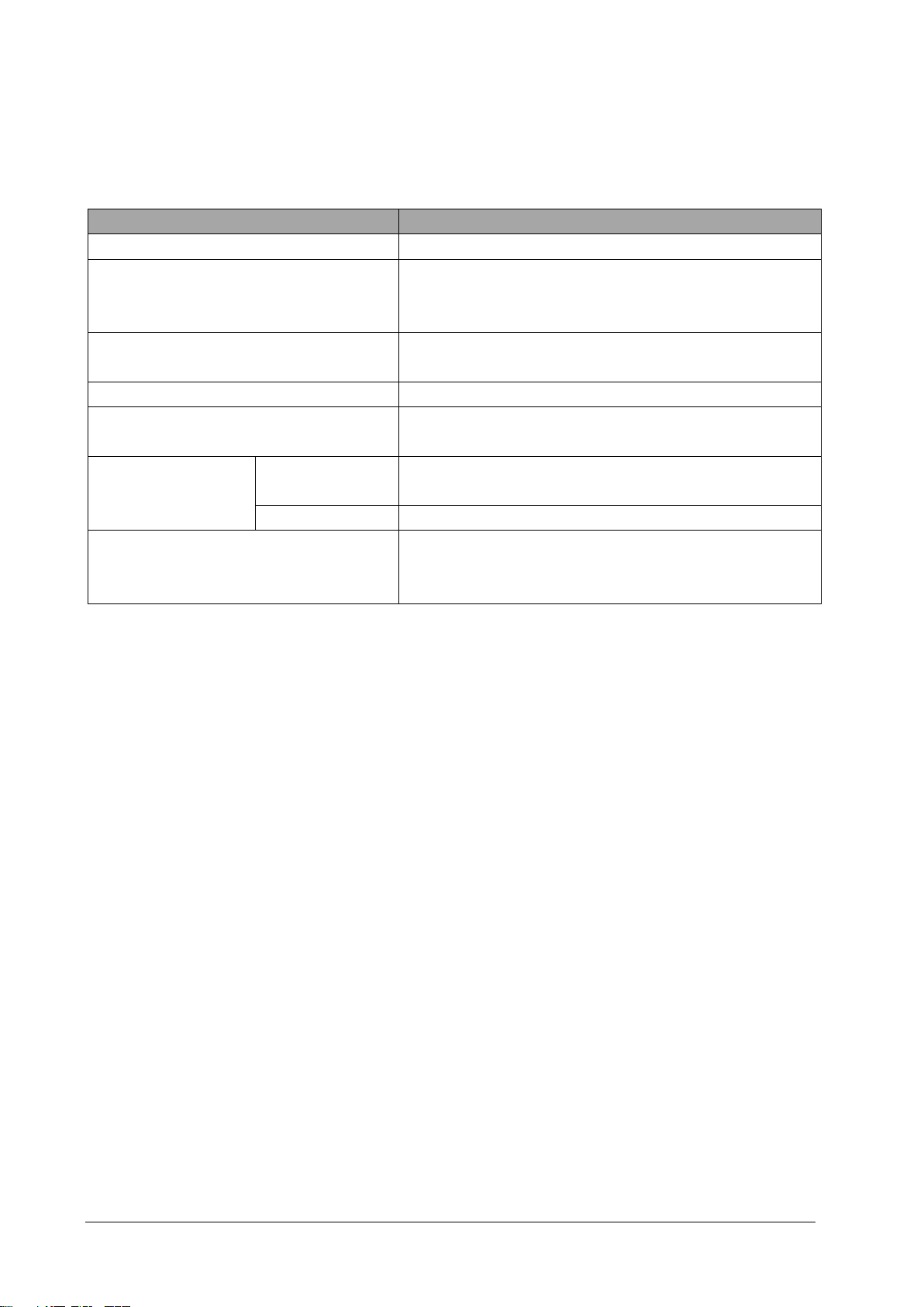
3.4 Electrical Safety and Other Tests
3.4.1 Electrical Safety and Other Test Frequencies
Check/Maintenance Item Frequency
Electrical safety tests Refer to Appendix A Electrical Safety Inspection.
1. When first installed or reinstalled.
Power on test
Touchscreen calibration
Recorder check Following any repair or replacement of the recorder.
Network print test
Battery check Function test 1. When first installed.
Performance test Once a year or if the battery run time is significantly reduced.
iView System Maintenance 1. When first installed.
3.4.2 Electrical Safety Test
See Appendix A Electrical Safety Inspection for electrical safety tests.
3.4.3 Power On Test
This test is to verify that the patient monitor can power up correctly. The test is passed if the patient monitor starts up
by following this procedure:
2. Following any maintenance or the replacement of any main unit
parts.
1. When the touchscreen accuracy diminishes.
2. After the touchscreen is replaced.
1. When first installed.
2. Whenever the printer is serviced or replaced.
2. Whenever a battery is replaced.
2. Whenever the iView board is replaced.
3. When the system software is updated.
1. Insert two batteries in the battery chamber and connect the patient monitor to the AC mains, the AC mains LED
and battery LED light.
2. Press the power on/off switch to switch on the patient monitor. The operating status LED lights up, and the
technical and physiological alarm lamps light blue and red respectively.
3. After the start-up screens are displayed, the system sounds a beep indicating the self test on alarm sounds is
passed. At the same time, the alarm lamp turns from yellow to red, and then turns off together with the technical
alarm lamp. This indicates that the self test on alarm lamps is passed.
4. The patient monitor enters the main screen and start-up is finished.
3-18 Passport 17m Service Manual
Page 47

Note
3.4.4 Touchscreen Calibration
Tools required:
None.
1. Select [Main Menu] → [Maintenance >>] → [Cal. Touchscreen]. The
positions on the screen.
2. Touch, in turn, the central point of the
Calibration Completed!] is displayed.
3. Select [Ok] to confirm.
symbol. After the calibration is completed, the message [Screen
symbol will appear at different
3.4.5 Recorder Check
Tools required:
None.
1. Print ECG waveforms. The recorder should print correctly and the printout should be clear.
2. Remove the paper roll to generate an out of paper error. The patient monitor should display the proper message
for the condition created. After the problem is removed, the recorder should work properly.
3. Switch on automatic alarm recording for each parameter and then set each parameter’s limit outside set alarm
limits. Corresponding alarm recordings should be triggered when parameter alarms occur.
3.4.6 Network Print Test
Use the recommended printers specified in the operator’s manual (PN: 046-005013-00).
Tools required:
Hub and network cable
3.4.6.1 Equipment Connection and Setup
1. Connect the patient monitor and network printer to a HUB using common network cables as follows:
Passport 17M
monitor
Cable Cable
HUB
Network printer
Passport 17m Service Manual 3-19
Page 48

2 Set IP address as follows: Select [Main Menu] → [Maintenance >>] → [User Maintenance >>] → enter the
required password → [Network Setup >>] → [Monitor Network Setup >>], set the IP address of the patient
monitor in the same network segment with that of the network printer. (See the instructions for use
accompanying the printer)
3 Search for printer by selecting [Main Menu] → [Print Setup >>] → [Printer Setup >>] → [Search Printer]. After
a while, the printer’s model and IP address will appear in the box beside [Printer].
3.4.6.2 Print Function Test
1 Enter the Demo mode of the patient monitor.
2 Select [Main Menu] → [Print Setup >>] → [Realtime Reports >>] → [Normal Report] and then select [Print].
The network printer should print out the report correctly.
3.4.7 Battery Check
Tools required:
None.
3.4.7.1 Function Test
1. Remove any batteries that are installed in the patient monitor.
2. Verify that the patient monitor works properly when running on AC power.
3. Insert two fully charged batteries per the procedures provided in the Operators’ Manual.
4. Remove the AC power cord and verify that the patient monitor still works properly.
3.4.7.2 Performance Test
Perform the test procedure in the Battery chapter in the Operators’ Manual and verify the operating time of the
battery meets the product specification.
3.4.8 iView System Maintenance
3.4.8.1 Making USB Startup Disk
Tools required:
MakeUSB (PN: 110-002149-00)
USB drive with capacity greater than 4GB
3-20 Passport 17m Service Manual
Page 49
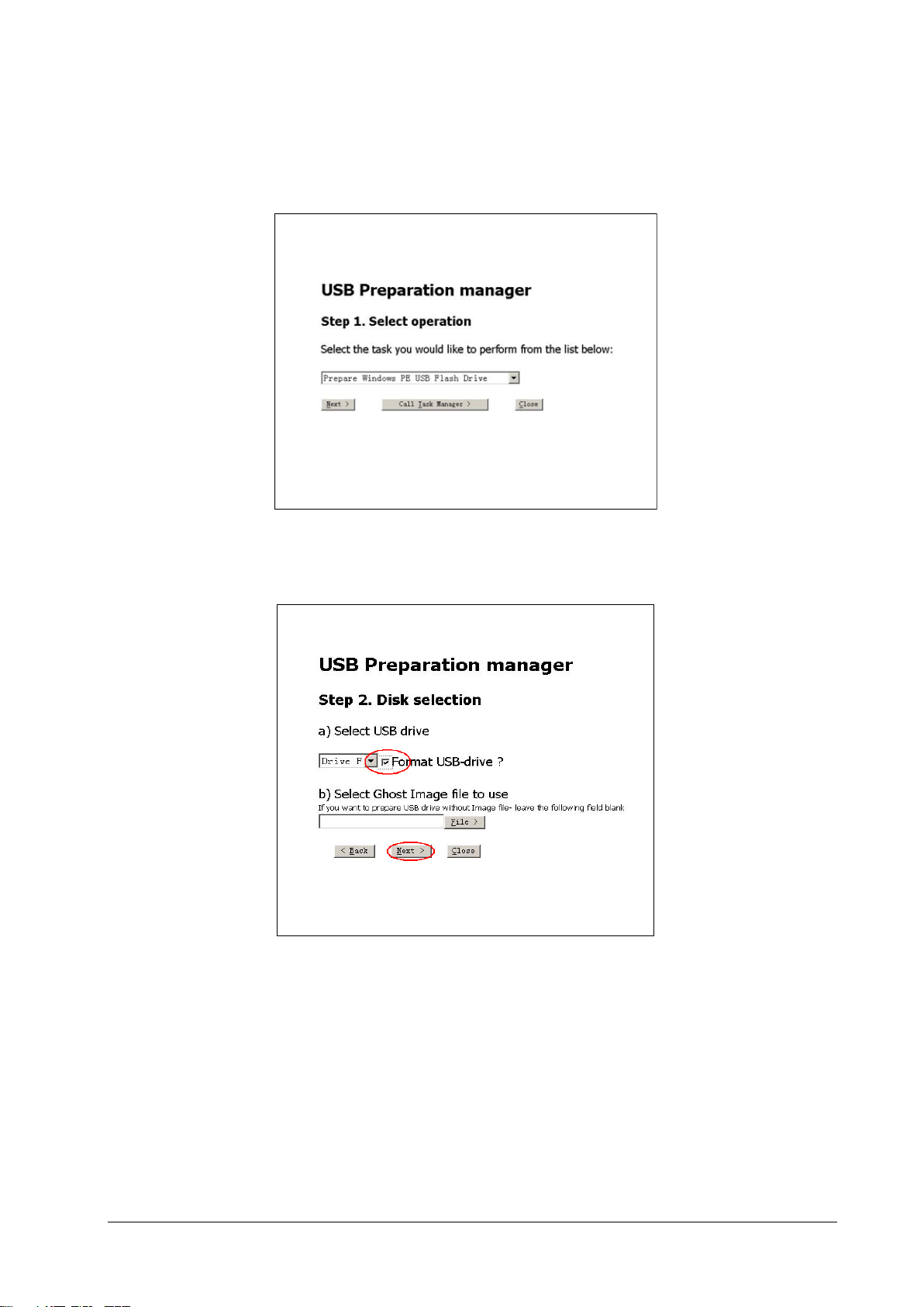
1. Insert the USB drive into the PC.
2. Run “prepareUSB.hta” file in the MakeUSB folder.
3. Select [Prepare Windows PE USB Flash Drive] in the drop-down list, and select [Next>].
4. Select the drive label of the USB drive in the drop-down list, and put a check mark in the box labeled [Format
USB-drive
5. The system selects [Full mode] and [Manual mode] by default. Select [Prepare USB>] to start making the
startup disk.
?]. [Select Ghost Image file to use] is unselected by default. Then select [Next>].
Passport 17m Service Manual 3-21
Page 50
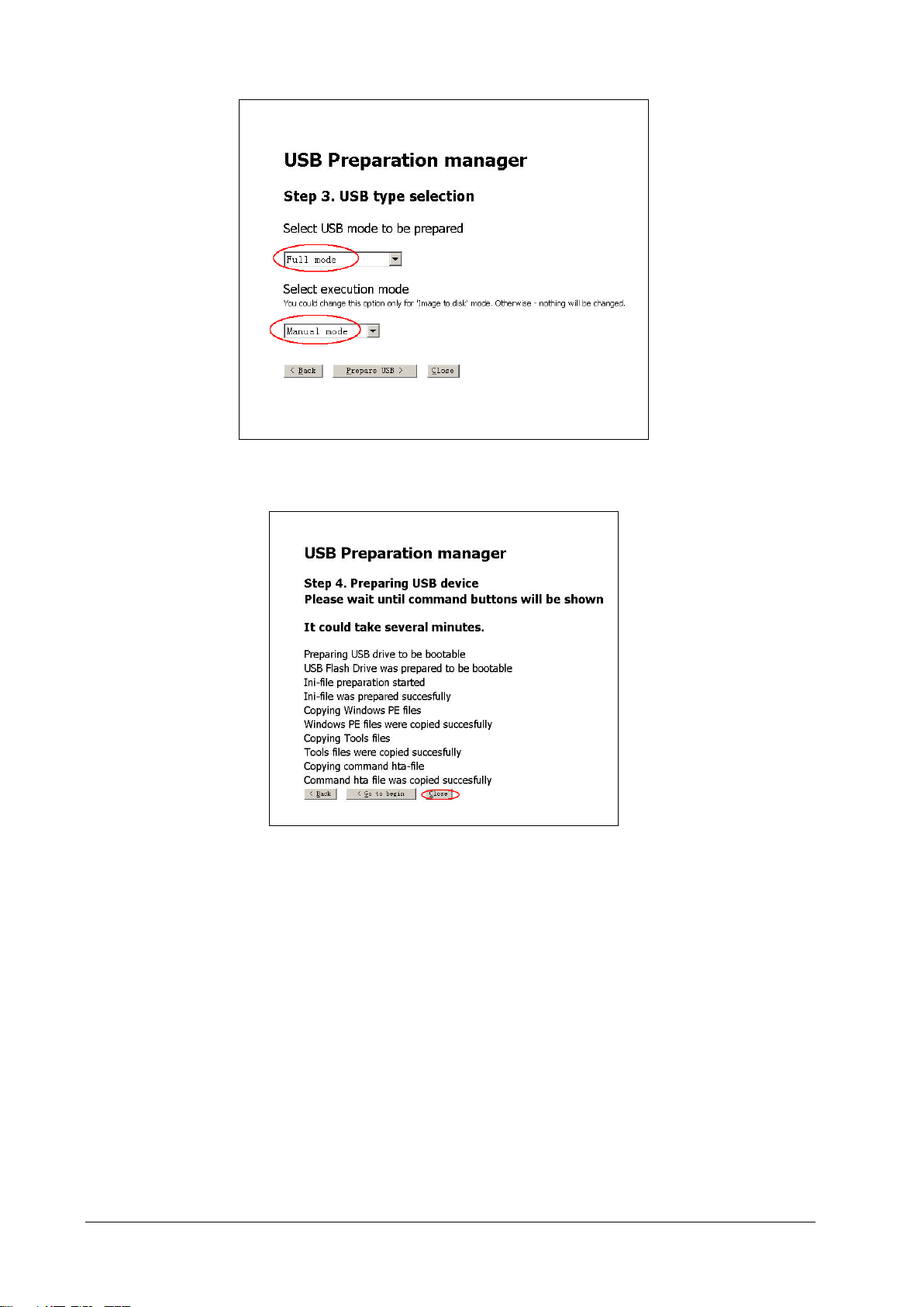
6. Select [Close] to finish.
3.4.8.2 Restoring the System
Connecting the External USB Cable
Connect the iView maintenance USB disk which stores the system image files and keyboard. You must use the special
iView USB connector to restore the system.
3-22 Passport 17m Service Manual
Page 51
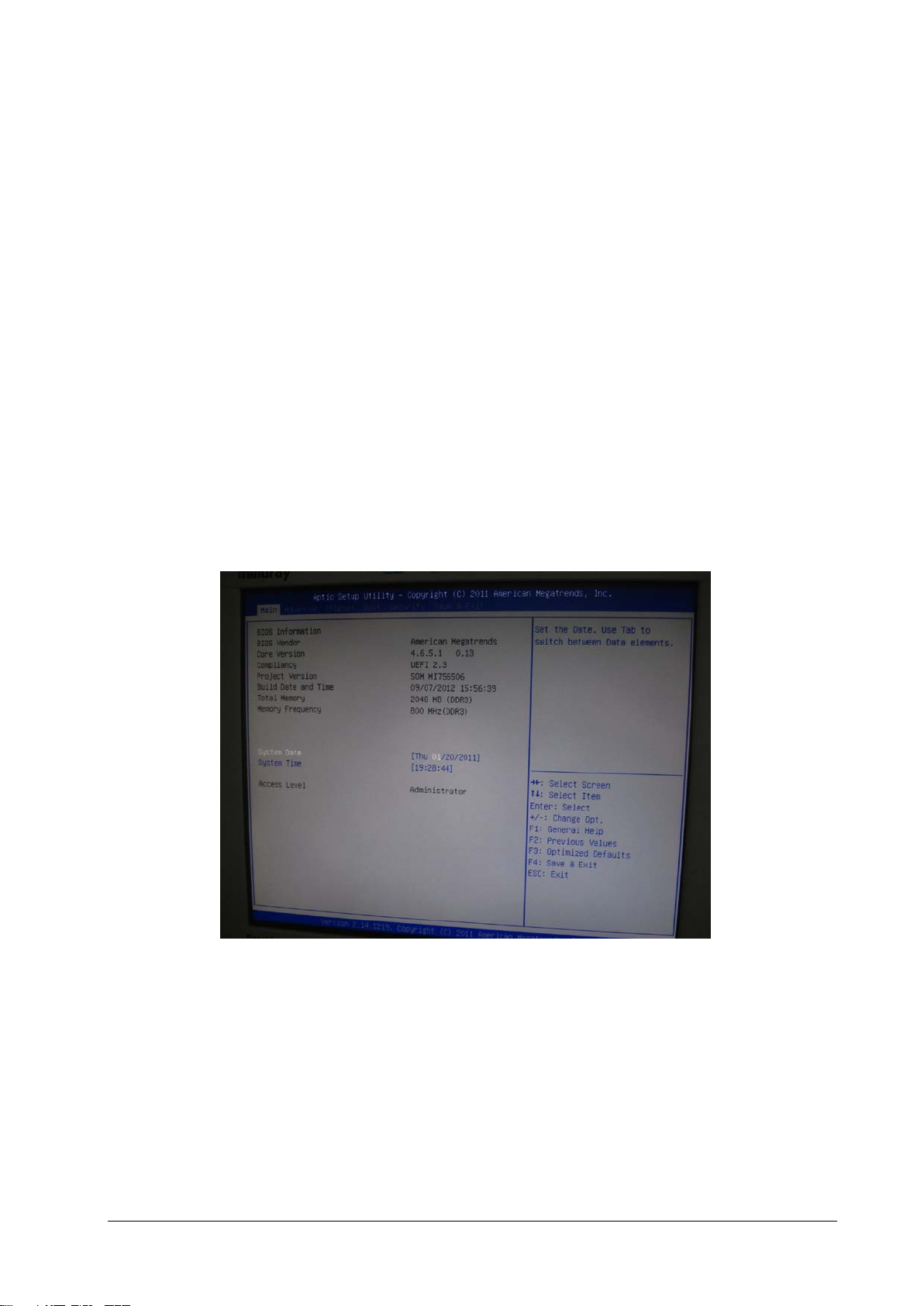
Setting BIOS Screen
1. Start up the patient monitor and press [F2] key repeatedly.
2. Select [Main Menu] → [Maintenance>>] → [User Maintenance>>] → enter the required password →
[iView Maintenance>>] → [iView Setup], and when the system switches to BIOS setup screen, release the [F2]
key.
3. Move the cursor to [Boot] by pressing [←] or [→] keys on the keyboard. Then press [Enter] on the keyboard.
4. Move the cursor to [1st Boot], and press [Enter] on the keyboard.
5. Select [USB] and press [Enter] on the keyboard.
6. Move the cursor to [Save&Exit], and press [Enter] on the keyboard. Move the cursor to [Yes] and press [Enter]
on the keyboard to save the setup.
Restoring the system
To recover the iView system, follow these steps:
1. Start iView system, and press [F2] to enter BIOS. Select [Maintenance>>] → [User Maintenance >>] → enter the
required password → [iView Maintenance>>] → [iView Setup], and enter the following screen.
2. Select [Boot] in the menu bar, and then select option of [1st Boot] in the submenu. Press enter key, and select
[USB] in the popup window.
Passport 17m Service Manual 3-23
Page 52
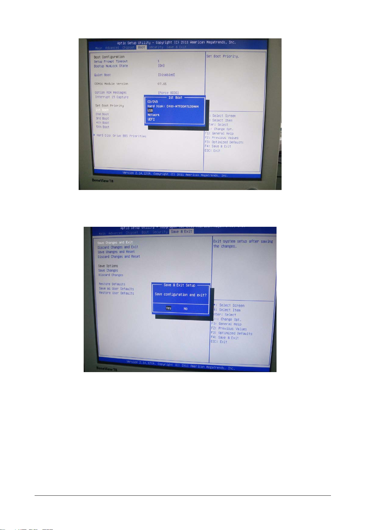
3. Select [Save&Exit] in the menu bar. Then select the option of [Save Changes and Exit] in the submenu and
press [Enter] key. After that, select [Yes] to exit.
4. Insert the USB disk for iView maintenance (P/N: 115-017183-00) into the special USB connector for iView system
on the rear housing of the Passport 17m. The following screen will be displayed. Click the arrow, and the
drop-down list will appear. Select [Ghost image to disk] from the list. Click [Next].
3-24 Passport 17m Service Manual
Page 53
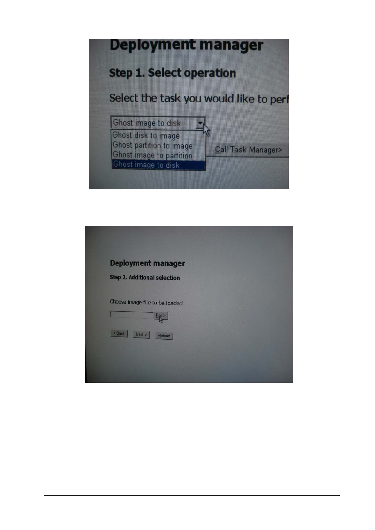
5. Click [File] as shown in the below figure, and then choose the path to the image file you wish to load.. Click [OK].
Then select [Next].
Passport 17m Service Manual 3-25
Page 54
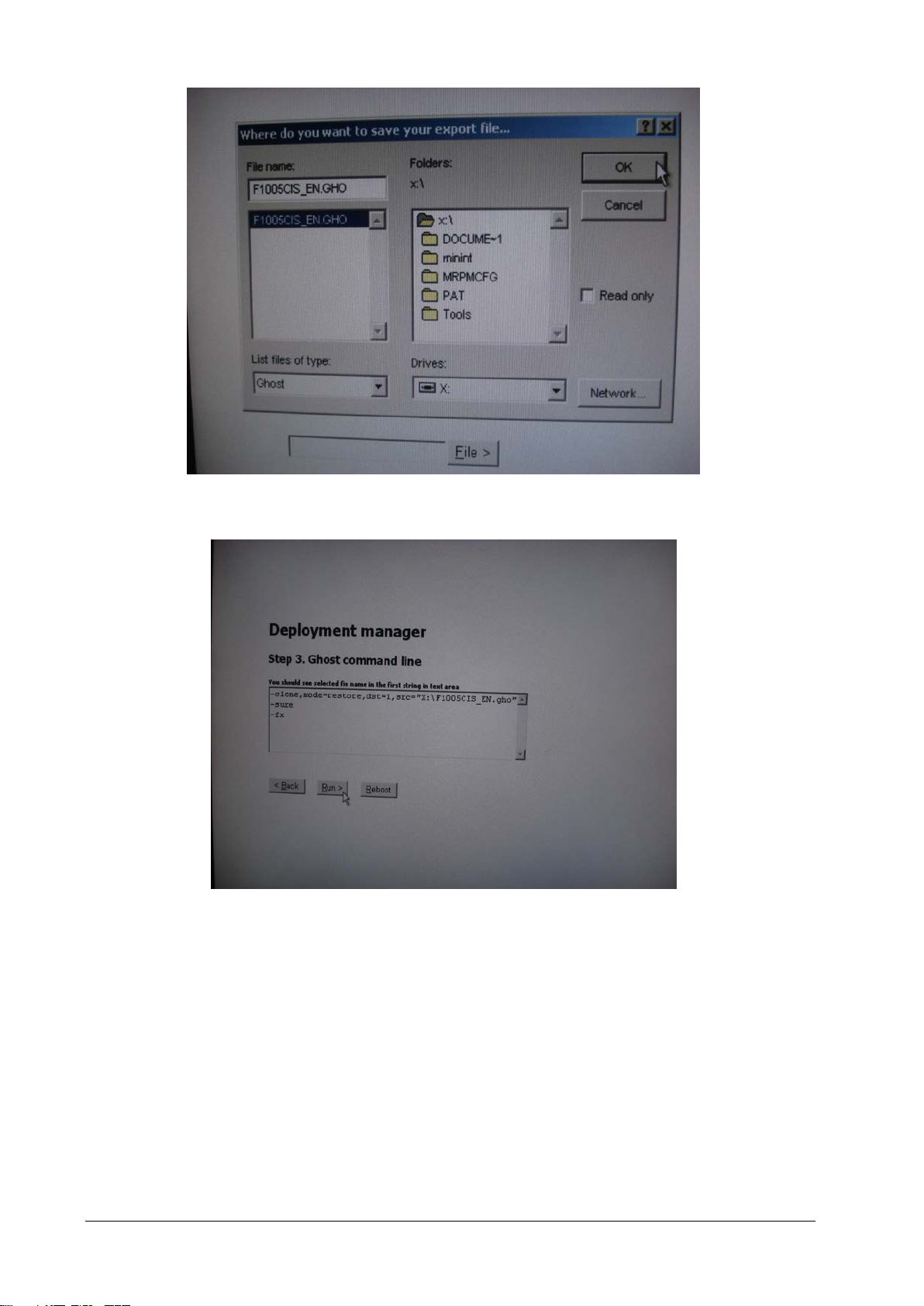
6. Select [Run>] to start the image recovery process.
3-26 Passport 17m Service Manual
Page 55
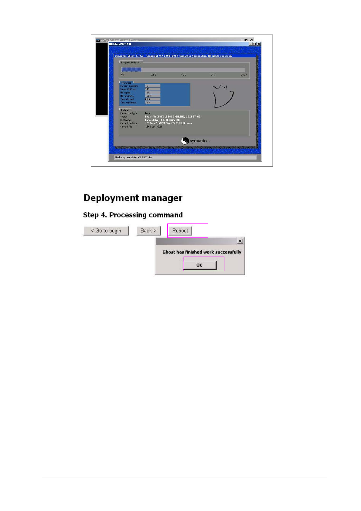
7. Click [OK], and then click [Reboot]. When the monitoring screen of Passport 17m appears, remove the iView
maintenance USB disk. The system will restart in the Windows 7 mode. A prompt to activate WIN7 will appear.
8. Start the activation of Windows 7 system and enter the following screen.
Passport 17m Service Manual 3-27
Page 56
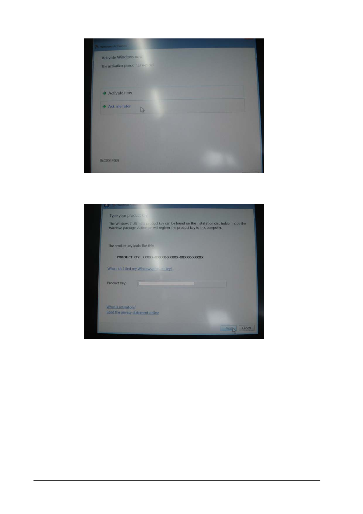
9. Input the key number.
3-28 Passport 17m Service Manual
Page 57
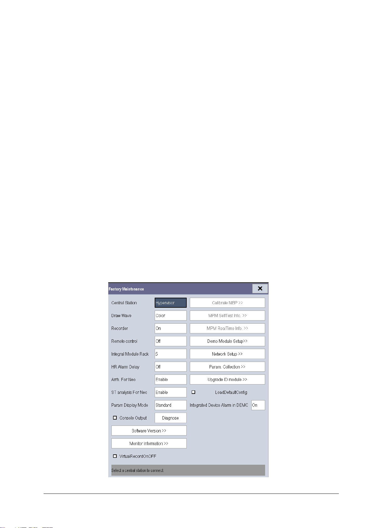
3.4.8.3 Setting Automatic Login
iView system is set to be automatically logged in by default. However, if the registry is modified, which requires a
manual login, you can restore to the automatic login by doing the following:
1. Select [Run] in the [Start] menu of the Windows system.
2. Type in ‘regedit’, and then click [OK]. The [Registry Editor] window will pop up.
3. In the [Registry Editor] window, determine what the following three value entries are under
HKEY_LOCAL_MACHINE\SOFTWARE\Microsoft\Windows NT\CurrentVersion\Winlogon. Check and change (if
necessary) the value according to what is shown below (the value is case sensitive).
"AutoAdminLogon" = "1"
"DefaultUserName" =“CIS"
"DefaultPassword" =“MINDRAY"
If some value entry does not exist for any of the three items listed, you have to create one: right click the mouse, select
[New] → [String Value], and enter the string as the name of the new value entry along with the correct value.
3.5 Factory Maintenance
3.5.1 Accessing Factory Maintenance Menu
To access the factory maintenance menu, select [Main Menu] → [Maintenance >>] → [Factory Maintenance] and
then enter the required password.
The [Factory Maintenance] menu is shown below.
Passport 17m Service Manual 3-29
Page 58
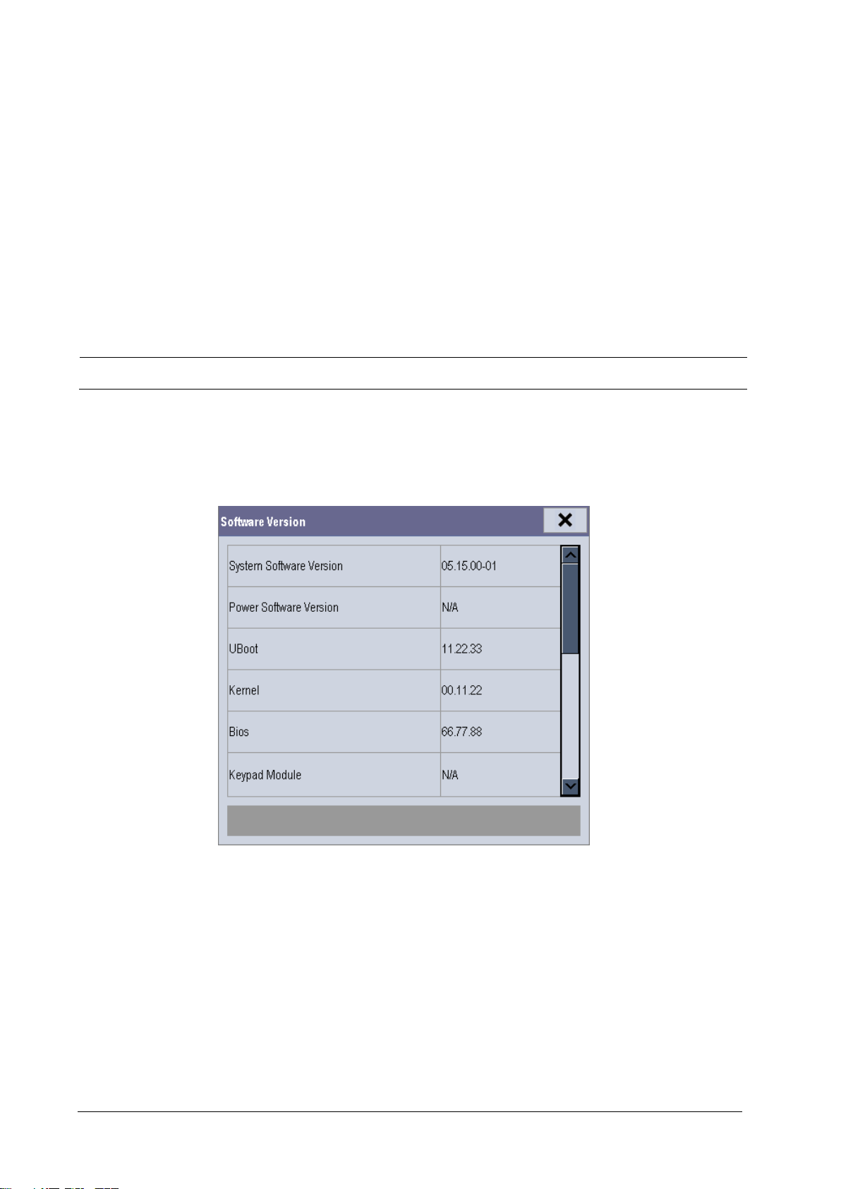
3.5.2 Drawing Waves
In the [Factory Maintenance>>] menu, select [Draw Wave] to define the method to draw waves. There are two
methods to draw waves:
Color: selecting Color will have smoother waveforms.
Mono: selecting Mono will have a wider viewing angle.
3.5.3 Enabling/Disabling the Recorder
To enable/disable the recorder, select [Recorder] and toggle between [On] and [Off].
CAUTION
The recorder is disabled if [Recorder] is switched off in the [Factory Maintenance>>] menu.
3.5.4 Checking Software Version
In the [Factory Maintenance] menu, select [Software Version] to show software version information. The [Software
Version] menu is as follows:
3-30 Passport 17m Service Manual
Page 59
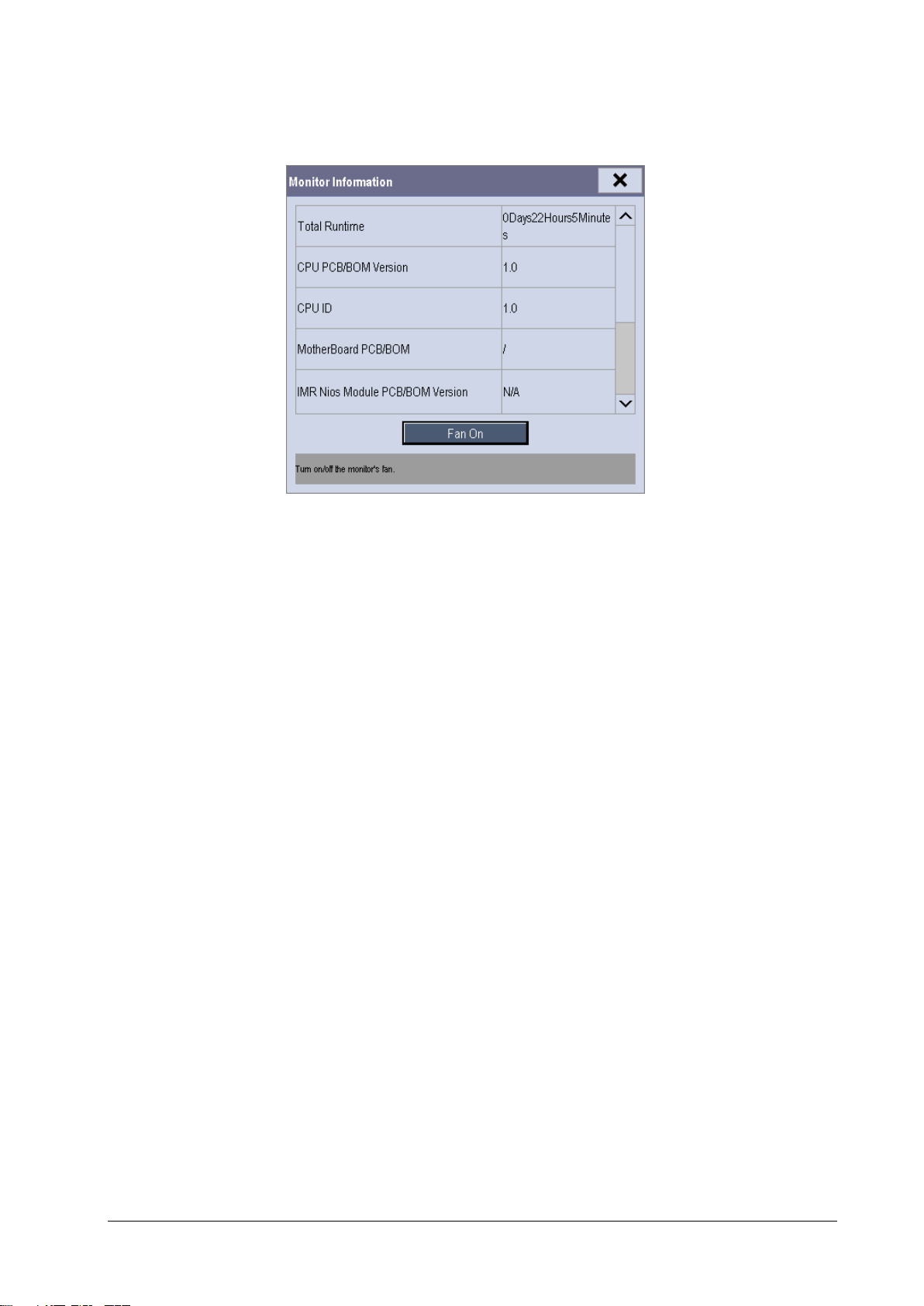
3.5.5 Checking Monitor Information
In the [Factory Maintenance] menu, select [Monitor Information] to show the status of the patient monitor.
Passport 17m Service Manual 3-31
Page 60

FOR YOUR NOTES
3-32 Passport 17m Service Manual
Page 61

4 Troubleshooting
4.1 Introduction
In this chapter, patient monitor problems are listed along with possible causes and recommended corrective actions.
Refer to the tables to check the patient monitor, identify and eliminate these problems.
For more information on troubleshooting, contact our Mindray Technical Support Department.
4.2 Part Replacement
Printed circuit boards (PCBs), major parts and components in patient monitors are replaceable. Once you isolate a PCB
you suspect defective, follow the instructions in Repair and Disassembly to replace the PCB with a known good one.
Verify proper operation and that the patient monitor passes all performance tests.
To obtain information on replacement parts, refer to Parts.
4.3 Patient Monitor Status Check
Some troubleshooting tasks may require you to identify the hardware version and status of your patient monitor.
1. To view the information on system start time, self check, etc., select [Main Menu] → [Maintenance >>] →
[Monitor Information >>].
2. You can also view the information on the monitor’s current status by selecting [Main Menu] →[Maintenance>>]
→ [Factory Maintenance>>] → enter the required password → [Monitor Information >>].
4.4 Software Version Check
Some troubleshooting tasks may require you to identify the configuration and software version of your patient
monitor.
1. To view information on the system configuration and system software version, Select [Main Menu] →
[Maintenance>>] → [Software Version>>].
2. You can also view the information on system software version and module software version by selecting [Main
Menu] → [Maintenance>>] → [Factory Maintenance>>] → enter the required password →[Software
Version>>].
Passport 17m Service Manual 4-1
Page 62
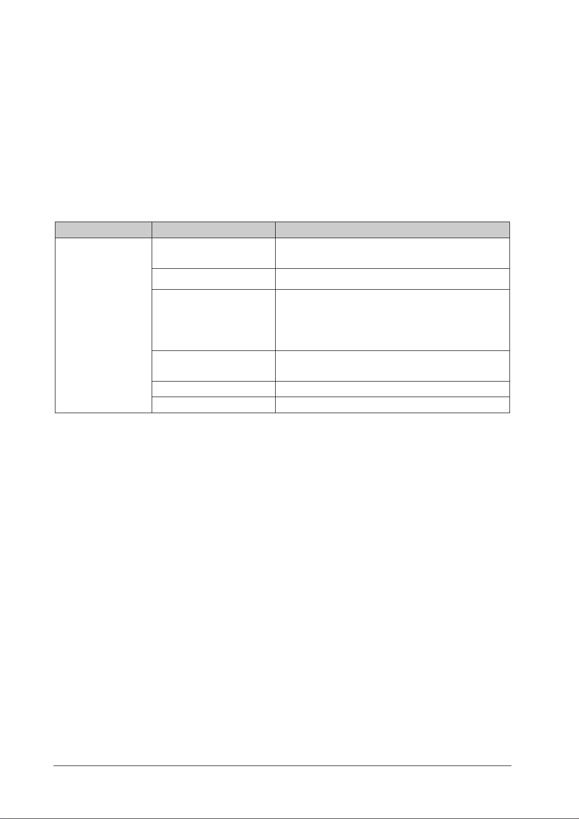
4.5 Technical Alarm Check
Before troubleshooting the patient monitor, check for technical alarm message. If an alarm message is presented,
eliminate the technical alarm first. For detailed information on technical alarm messages, possible causes and
corrective actions, refer to the 17m’s Operat ion Manual.
4.6 Troubleshooting Guide
4.6.1 Power On/Off Failures
Symptoms Possible Cause Corrective Action
The patient monitor
fails to start. AC LED or
battery LED does not
light
AC mains not connected or
battery too low
Power supply protection Refer to 4.6.9 Power Supply Failures .
Cables defective or poorly
connected
Power switch & LED board
defective
Power module defective Replace the power module.
Mother board Defective Replace the mother board.
Verify the AC mains is properly connected or battery capacity
is sufficient.
1. Verify the cables from power switch & LED board to
button board, button board to main board, and power
module to main board are correctly connected.
2. Verify the cables and connectors are not damaged.
Replace the power switch & LED board.
4-2 Passport 17m Service Manual
Page 63
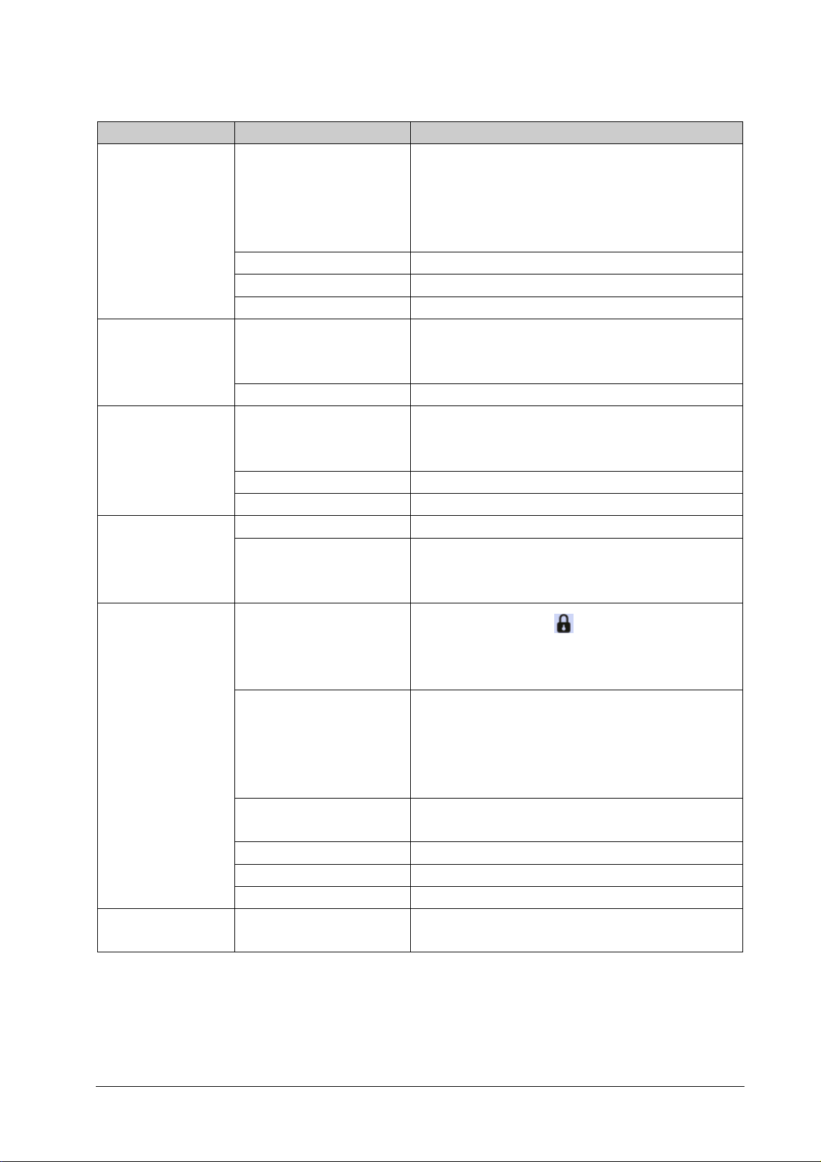
4.6.2 Display Failures
Symptoms Possible Cause Corrective Action
Integrated display is
blank.
Secondary display does
not function.
Secondary display
shows snow or flashing
specks
Images overlapped or
distorted
Touchscreen does not
respond
Touch screen accuracy
is off
Cables defective or poorly
connected.
Backlight board defective Replace the backlight board.
Power module defective Replace the power module.
Display defective Replace the display.
Cables defective or poorly
connected.
DVI interface board defective Replace the DVI interface board.
Cables defective or poorly
connected.
DVI interface board defective Replace the DVI interface board.
The mother board is defective. Replace the mother board.
FPGA error. Update or upgrade FPGA.
Cables defective or poorly
connected.
Touchscreen disabled
Cables defective or poorly
connected.
Touchscreen control board
defective
Button board defective. Replace the button board.
Touchscreen defective. Replace the touchscreen.
Mother board defective Replace the mother board.
Touchscreen needs to be
calibrated
1. Verify the cable from the display to the mother board
and the cables from the backlight board respectively to
the button board and the display are correctly
connected.
2. Verify the cables and connectors are not damaged.
1. Verify the cable between the secondary display and the
patient monitor is correctly connected.
2. Verify the cables and connectors are not damaged.
1. Verify the cable between the display and the patient
monitor is correctly connected.
2. Verify the cables and connectors are not damaged.
1. Verify the cable between the display and mother board is
correctly connected.
2. Verify the cables and connectors are not damaged.
Check if there is a symbol
Menu] QuickKey. If yes, press the [Main Menu] QuickKey for
more than 3s to enable the touchscreen.
1. Verify the cables from the touchscreen to the
touchscreen control board, the touchscreen control
board to the button board, and the button board to the
mother board are correctly connected.
2. Verify the cables and connectors are properly connected.
Replace the touchscreen control board.
Calibrate the touchscreen.
shown above the [Main
Passport 17m Service Manual 4-3
Page 64
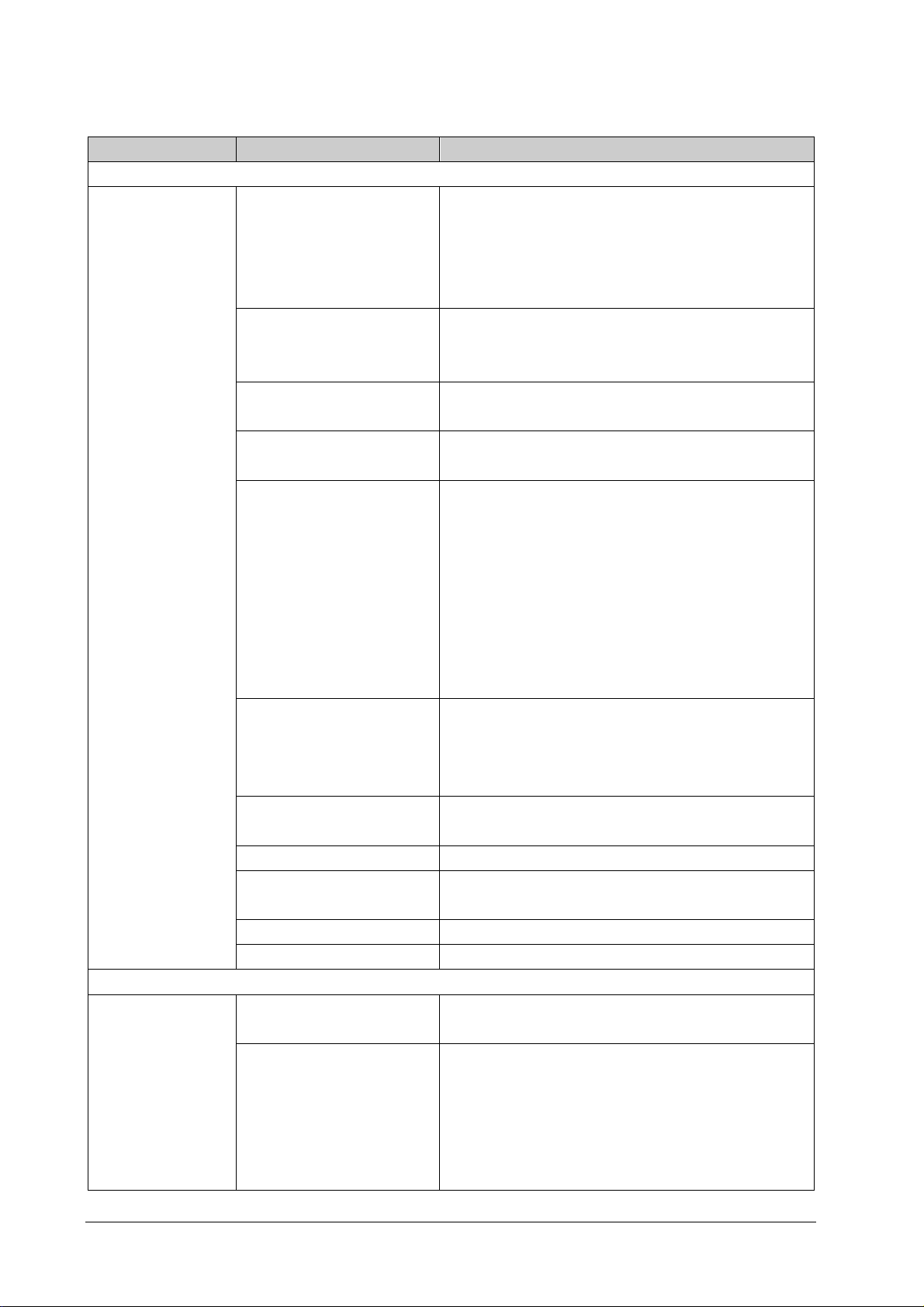
4.6.3 Module Rack Failures
Symptoms Possible Cause Corrective Action
SMR
SMR cannot identify
parameter modules
Integral module rack
Integral module rack
cannot identify
parameter modules
Extension Cable defective or
improperly connected
Defective parameter module Replace the malfunctioning parameter module with a known
Wrong communication board
software revision
Module is not recognized in all
slots, only certain slots.
Power supply failure 1. Verify there is 12VDC potential as measured across two
Cable defective or improperly
connected
Nios II module loose or not
working
SMR interface board failure Replace the SMR interface board.
SMR communication board
failure
USB_Hub board failure Replace the USB_Hub board.
Mother board failure Replace the mother board.
Module failure Replace parameter module. If a new module is identified, the
Cable defective or improperly
connected
1. Verify the powered USB cable between SMR and main
unit is connected to the SMR connector on the monitor.
2. Verify the connecting cables and connectors are not
damaged.
3. Check that contact screws on SMR are tight.
good module. If the patient monitor identifies the
replacement module, the original module is faulty.
Upgrade the module and/or the SMR software to a
compatible level.
Replace the Nios II module.
Replace the 8-slot module rack communication board.
contact points for a module slot. If yes and the parameter
module functions properly then the PCB assembly in
SRM might be faulty.
2. If there is no 12 VDC power sent to the SMR, check
whether the power voltage output to the USB_Hub
board by the power module reaches 12VDC. If yes, the
fuse of the USB interface board might be open. Replace
the USB_Hub board.
1. Verify the cable between the SMR interface board and
the communication board is properly connected.
2. Verify the connecting cables and connectors are not
damaged.
1. Verify the Nios II module is correctly connected
2. If the symptom persists, replace the Nios II module.
Replace the SMR communication board.
original one is defective.
1. Verify the cables from the 3-slot module rack
communication board to the MPM module rack
communication board, and the module rack to the
mother board are properly connected.
2. Verify the connecting cables and connectors are not
damaged.
4-4 Passport 17m Service Manual
Page 65
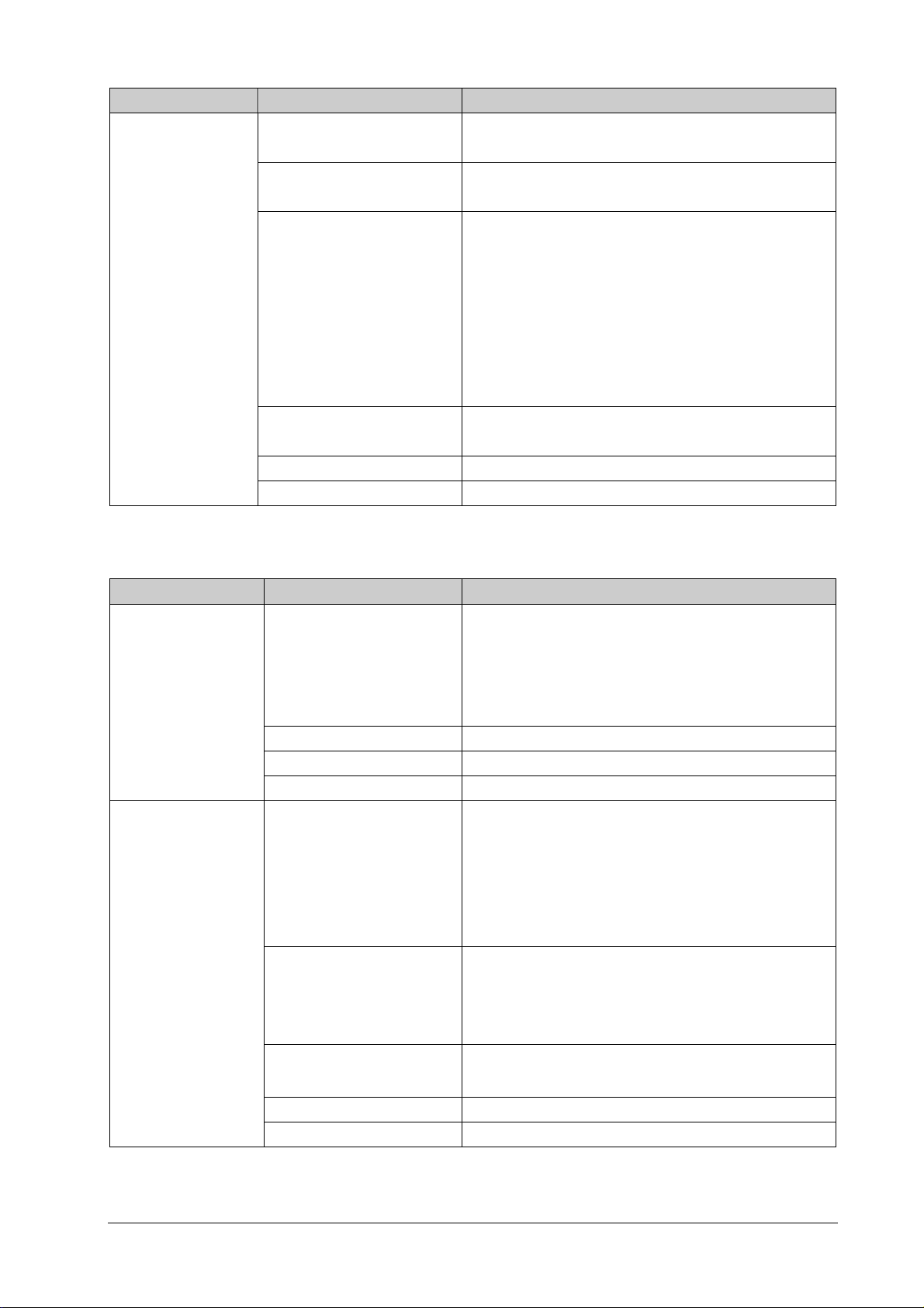
Symptoms Possible Cause Corrective Action
Wrong communication board
software revision
Module is not recognized in all
slots, only certain slots.
Power supply to integral
module rack is not correct
3-slot or MPM module rack
communication board failure
Nios II module failure Replace the Nios II module.
Mother board failure Replace the mother board.
Upgrade the module or the integral module rack software to
a compatible version.
Replace the corresponding module rack communication
board.
1. Verify there is 12VDC potential as measured across two
contact points for a module slot. If yes and the parameter
module functions, PCB assembly in the SMR might be
faulty.
2. If there is no 12VDC sent to the integrated module rack,
verify the power module output voltage to the mother
board reaches 12VDC. If yes, the mother board might be
faulty.
Replace the 3-slot or MPM module rack communication
board.
4.6.4 Alarm Problems
Symptoms Possible Cause Corrective Action
No visual alarm
indicator when the
audible alarm is
sounding.
No audible alarm
sounds emitted when
visual alarm is
activated.
Cable defective or improperly
connected
Alarm LED board failure Replace the alarm LED board.
Button board failure Replace the button board.
Mother board failure Replace the mother board.
Audible alarm disabled
Cable defective or poorly
connected
1. Verify the cables from the alarm LED board to the button
board and button board to the mother board are
properly connected.
2. Verify the connecting cables and connectors are not
damaged.
Select [Main Menu] → [Maintenance >>] → [User
Maintenance >>] → enter the required password →
[Alarm Setup >>], and then in the popup menu, set
[Minimum Alarm VolumeAlm Sound] to appropriate
setting.[On] In the [Others] window of the [Alarm Setup]
menu, set [Alm Volume] to appropriate setting.
1. Verify the cable between speaker and mother board is
properly connected.
2. Verify the connecting cables and connectors are not
damaged.
FPGA audio logic error Upgrade the audio logic part of the FPGA program.
Speaker failure Replace the speaker.
Mother board failure Replace the mother board.
Passport 17m Service Manual 4-5
Page 66
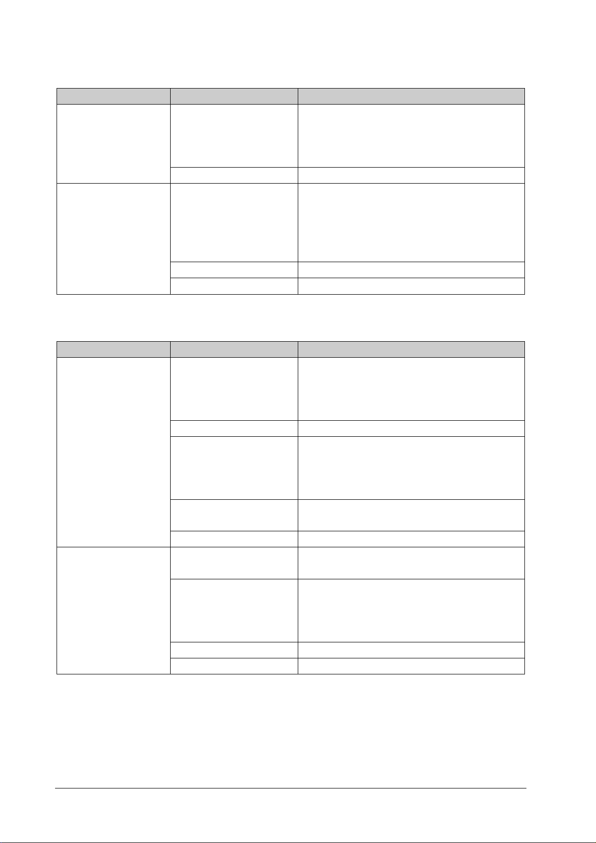
4.6.5 Button and Knob Failures
Symptoms Possible Cause Corrective Action
Buttons do not work Cable defective or poorly
connected
Button board failure Replace the button board.
Rotary encoder does not
work
Cable defective or improperly
connected
Encoder failure Replace the encoder.
Button board failure Replace the button board
1. Verify the cable between the button board and
mother board is properly connected.
2. Verify the connecting cables and connectors are not
damaged.
1. Verify the cables from the knob to the button board,
and the button board to the mother board are
properly connected
2. Verify the connecting cables and connectors are
undamaged.
4.6.6 Recorder Failures
Symptoms Possible Cause Corrective Action
No printout Recorder module disabled 1. Verify the recorder status LED is lit
2. If yes, enable the module in the [Factory
Maintenance] menu. If it is not lit, check for other
possible causes.
Paper is installed upside down Remove and reinstall the paper roll properly
Poor print quality or paper
not feeding properly
Cable defective or improperly
connected
Recorder power supply failure Verify the power module’s 5 VDC and 12VDC outputs are
Recorder failure Replace the recorder.
Paper roll not properly
installed
Print head dirty 1. Verify the thermal print head and the paper roller for
Print head failure Replace the recorder.
Recorder failure Replace the recorder.
1. Verify the cable between the recorder and the
mother board is properly connected.
2. Check that the connecting cables and connectors are
not damaged.
present.
Stop the recorder and re-install the paper roll.
foreign matter.
2. Clean the thermal print head with an appropriate
cleaning solution.
4-6 Passport 17m Service Manual
Page 67
4.6.7 Output Interface Failures
Symptoms Possible Cause Corrective Action
No analog signals or nurse
call signals are generated
Connected USB devices
not working. (It is assumed
these devices are working
properly when connected
elsewhere).
Respective output disabled
USB_Hub board cable is
loose
USB_Hub board failure Replace the USB_Hub board.
Mother board failure Replace the mother board.
Cable defective or not
connected properly
USB_Hub board failure Replace the USB_Hub board.
Mother board failure Replace the mother board.
1. Select [Main Menu] → [Analog Output Setup] → set
[Analog Output] to [On].
1. Verify the cable between the USB_Hub board and the
mother board is properly connected.
2. Verify the connecting cables and connectors are not
damaged.
1. Verify the cable between the USB_Hub board and
mother board is properly connected.
2. Verify the connecting cables and connectors are not
damaged.
4.6.8 CF Card Problems
Symptoms Possible Cause Corrective Action
CF card malfunctions Wrong CF card or insufficient
storage capacity size
Data error; CF card error Format CF card on PC.
CF card failure Replace the CF card.
Cable defective or poorly
connected
CF card pcb failure Replace the CF card pcb.
Mother board failure Replace the mother board.
Use the storage card specified by Mindray. Those with 4GB
memory space are recommended.
1. Verify the cable between the CF card board and the
mother board is correctly connected.
2. Check that the connecting cables and connectors not
damaged.
Passport 17m Service Manual 4-7
Page 68
4.6.9 Power Supply Failures
Symptoms Possible Cause Corrective Action
Battery voltage is too low Battery failure Replace battery.
Cable defective or
improperly connected
Power board failure Replace the power board.
Battery cannot be recharged Battery failure Replace the battery and charge fully. If this is successful,
Cable defective or
improperly connected
Power board failure Replace power board
1. Power supply protected
No +3.3 VDC output
No +5.0 VDC output
No +5.0 VDC CIS output
2. Power board failure
1. Verify the cable is properly connected.
2. Verify the connecting cables and connectors are
not damaged.
the original battery is faulty.
1. Verify the cable between the battery interface
board and power module is correctly connected.
2. Verify the cables and connectors are not damaged.
1. Turn off the patient monitor then restart it.
2. If the problem remains, disconnect the AC mains
for 5 s and reconnect it, then restart the patient
monitor.
3. If the problem still remains, replace the power
board.
No +12 VDC output
NOTE
When the power module fails, it may cause damage to other components, e.g. the monitor suddenly fails
during start-up, due to supply protection. In this case, troubleshoot the power module per the procedure
described in the table above.
Components of the main unit, SMR and parameter modules are powered by the power module. In the
event that a component malfunctions, verify the operating voltage is correct. Refer to 2 Theory of
Operation for the operating voltage and measurement points for each component.
4-8 Passport 17m Service Manual
Page 69

4.6.10 Network Related Problems
Symptoms Possible Cause Corrective Action
The patient monitor cannot be
connected to iView system.
No connection to the LAN 1. Verify the cables and connectors are in good
condition and that the network is properly
connected.
2. Verify the hub or switch is properly configured.
iView assembly failure 1. Restart the patient monitor; verify a beep is heard.
2. After starting, select [Main Menu] →
[Maintenance>>] → [User Maintenance>>] →
enter the password required → [iView
Maintenance>>]. The [iView Setup] option should
be enabled and switching between the normal
monitor screen and the iView screen is possible.
3. If step 1 and 2 fail, verify the voltages supplied to
the iView assembly are correct. If the power supply
works properly, replace the iView assembly.
DVI interface board failure Replace DVI interface board.
Frequent dropouts and network
disconnects
The patient monitor is
connected to a LAN but cannot
view other patients in the View
Others mode
Improper LAN cable
connection
Improper IP address
configuration
Improper LAN cable
connection
More than 4 simultaneous
requests for viewing the
patient monitor
Incorrect IP configuration Check for IP address conflict. Reconfigure IP address.
iView assembly failure Replace iView assembly.
Check LAN cable connection. LAN cable should not be
longer than 50 m.
Check for IP address conflict. Reconfigure IP address.
Check LAN cable connection. LAN cable should not be
longer than 50m.
A patient monitor can only be viewed by 4 other
patient monitors simultaneously under the View Others
mode. Requests in excess of that number will be
ignored.
Passport 17m Service Manual 4-9
Page 70
4.6.11 Software Upgrade Problems
Symptoms Possible Cause Corrective Action
Bootstrap upgrade fails Power failure or unintended power
off during bootstrap upgrade
Program upgrade fails Incorrect network connection 1. Verify the network connector, NOT the iView
Wrong upgrade package has been
downloaded
Incorrect IP address configuration Configure the IP address to ‘77.77.1.xx’ (xx can be
Replace the CPU board.
network connector, on the patient monitor is
being used.
2. Verify the hub or switch operates properly.
Verify the network cables are the correct type
and have been connected properly.
Upgrade package should be .pkg files. Select
package according to system requirement.
any number between 1 and 253). We recommend
not to upgrade a program when the patient
monitor is connected to a network with multiple
PCs.
4.6.12 Technical Alarm Messages
Please refer to the Operators’ manual.
4.6.13 M51A Self Test Information
MPM module uses the integrative parameter board (ECG ASIC).
MPM Selftest Item Test Value Corrective Action
DSP selftest information
7024 selftest information
2131 selftest information
ECG module selftest information
Not FF Replace the module
4-10 Passport 17m Service Manual
Page 71
4.6.14 Device Integration Failures
Symptoms Possible Cause Corrective Action
1. Replace the ID adapter.
2. Upgrade the ID adapter in [Factory
The [Devices Integrated]
window displays nothing
after connection.
Generate the alarm:
[BeneLink Comm Stop].
The patient monitor has
no response when loading
the ID adap ter.
The ID adapter is not compatible
with the external device.
The serial port adapter cable is not
compatible with the external device.
Wrong software version or wrong
protocol version of the external
device.
The BeneLink module application
software is corrupted.
The BeneLink module application
software is corrupted.
The kernel or the document system
of the BeneLink module is damaged.
Maintenance] menu to make the ID adapter
match the corresponding external device. See
3.3.18.1 Device Connection and Setup for more
about the setup of the ID.
Replace the serial port adapter cable.
Make sure the protocol version and software version
are supported by the BeneLink module.
Update or upgrade the software application of the
BeneLink module with the network upgrading tool.
Update or upgrade the software application of the
BeneLink module with the network upgrading tool.
Return the BeneLink module to Mindray for repair.
Passport 17m Service Manual 4-11
Page 72

FOR YOUR NOTES
4-12 Passport 17m Service Manual
Page 73

5 Repair and Disassembly
5.1 Tools
During disassembly and repair, the following tools may be required:
Phillips screwdrivers
Small flat-bladed screwdrivers
Tweezers
Needle-nose pliers
Hex nut driver or socket wrench
5.2 Preparations for Disassembly
Before disassembling the monitor:
Stop monitoring the patient, turn off the monitor and disconnect all the accessories and peripheral devices.
Disconnect the AC power source and take out both of the batteries.
Remove all the modules in the integral module rack. If the SMR is connected, disconnect the SMR from the
monitor and then remove all the modules in it.
WARNING
Before disassembling the monitor, be sure to eliminate any static electricity charges. When
disassembling the parts labeled with static-sensitive symbols, make sure you are wearing electrostatic
discharge protection such as an antistatic wristband or gloves to avoid damaging the equipment.
Carefully position cables and wires to avoid short circuits and/or pinched tubing when reassembling the
monitor.
When assembling the monitor, be sure to use the specified screws. If an incorrect screw is tightened by
force, the monitor may be damaged and the screw or the part may fall off during use and cause
unpredictable damage or human injury.
Be sure to follow the correct sequence when disassembling the monitor. Be sure to disconnect all the
cables before disassembling any parts. Take care not to damage any cables or connectors.
Be sure to place the monitor face up when disassembling it. Otherwise, the screen or the knob may be
scratched or damaged.
Passport 17m Service Manual 5-1
Page 74
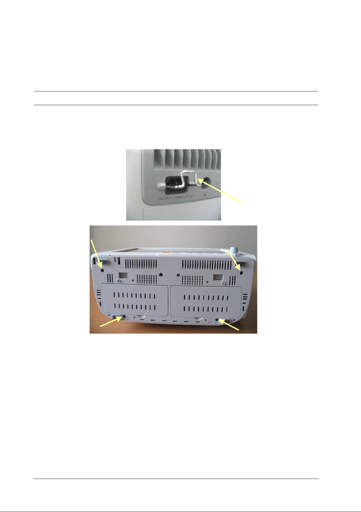
5.3 Basic Disassembly
5.3.1 Disconnecting the Base
NOTE
Be sure to disassemble the base first before proceeding with other parts.
1. The retainer that prevents the power plug from coming out is located beside the AC port in the rear case of the
monitor. Remove this retainer and then place the monitor face up and remove the four M4×12 screws, as shown
in the figure below.
5-2 Passport 17m Service Manual
Page 75
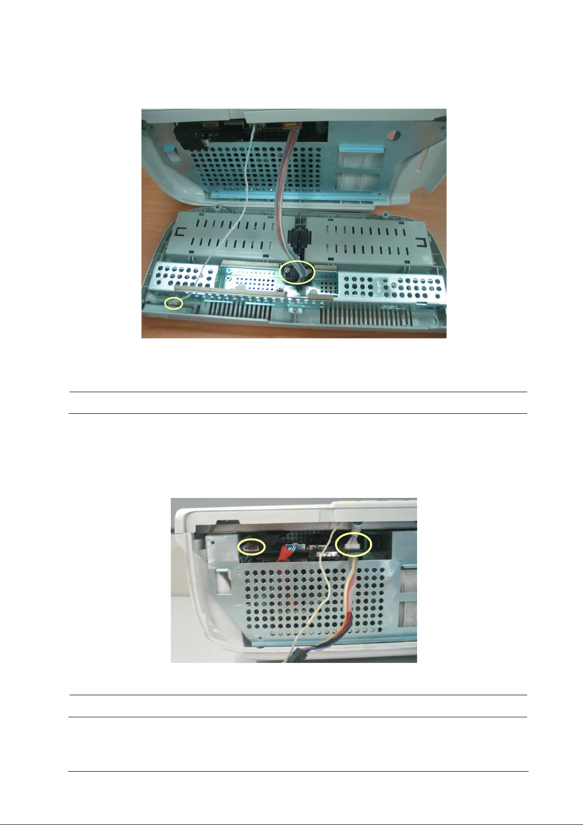
NOTE
2. Pull out the base and then unplug the two cables marked in the picture, one connecting the Power Switch &
LED board and the button board, and the other connecting the battery interface board and the power supply
assembly.
Exercise care when pulling the base out. Be sure not to damage the cables and connectors.
5.3.2 Separating the Front and Rear Half of the Monitor
1. Keep the monitor (without the base) face up. Disconnect the cables marked in the picture, one connecting the
LCD panel and the mother board, and the other connecting the button board and the mother board.
NOTE
Release the clip before disconnecting the cable between the button board and the mother board.
Passport 17m Service Manual 5-3
Page 76
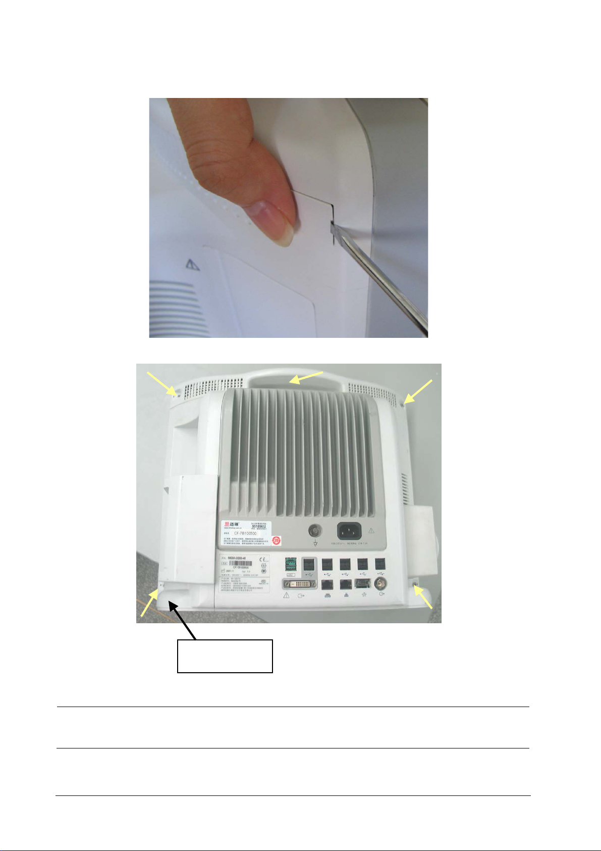
Avoid pressing the knob
on the table.
2. Carefully place the monitor face down. Pry up the four screw covers with a small flat-bladed screwdriver and
unscrew the four M3×12 screws. Then unscrew the M3×12 screw in the handle.
NOTE
Press the cover with a thumb when prying it.
Avoid pressing the knob on the table.
5-4 Passport 17m Service Manual
Page 77
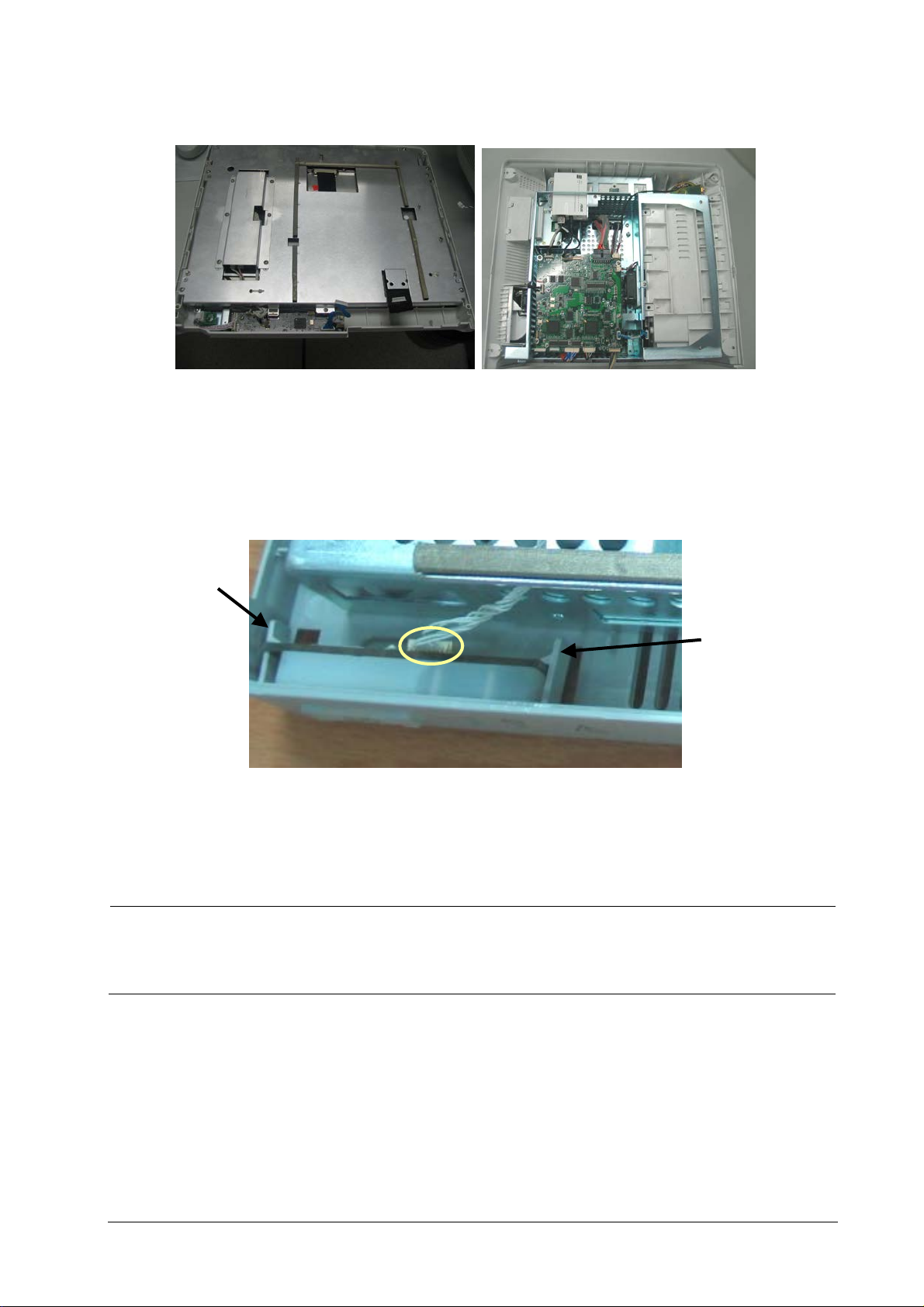
NOTE
Right Clip
Left Clip
3. Lift the rear cover assembly to separate it from the front cover assembly.
5.4 Further Disassembly
5.4.1 Removing the Power Switch & LED Board
1. Locate the cable marked in the picture and disconnect it from the power switch & LED board.
2. Release the clips with fingers. At the same time pinch the power switch & LED board, push it to the left and take it
out along with the power switch.
Exercise care whe releasing the clips.
When installing the LED board along with the power switch, put it on the left clip, push the right clip to
the right slightly, and then press the LED board down.
Passport 17m Service Manual 5-5
Page 78
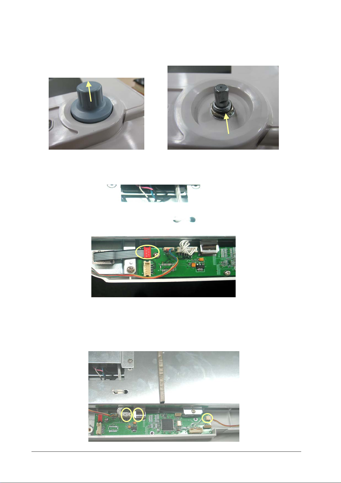
5.4.2 Disconnecting the Encoder Assembly
1. Pull the encoder knob off the shaft. Unscrew the hex nut.
2. Disconnect the cable that connects the encoder and the button board to remove the encoder.
5.4.3 Removing the Button Board
1. Disconnect the cables from the button board to the power switch & LED board, encoder, alarm LED board,
backlight board and, touchscreen control board and the mother board.
5-6 Passport 17m Service Manual
Page 79
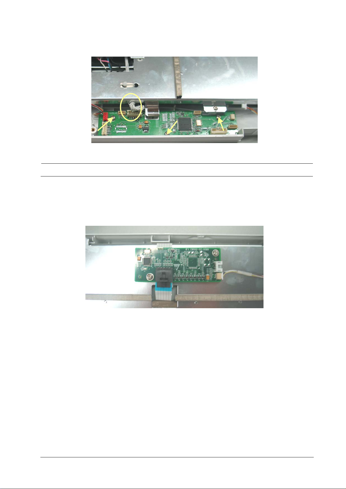
2. Remove the grounding spring and then remove the three PT3×8 screws and take out the button board.
NOTE
Do not forget the grounding spring when reassembling.
5.4.4 Removing the Touchscreen Control Board
Unplug the touchscreen cable and the cable from the button board to the touchscreen control board. Then, remove
the two M3×6 screws and remove the touchscreen control board.
Passport 17m Service Manual 5-7
Page 80
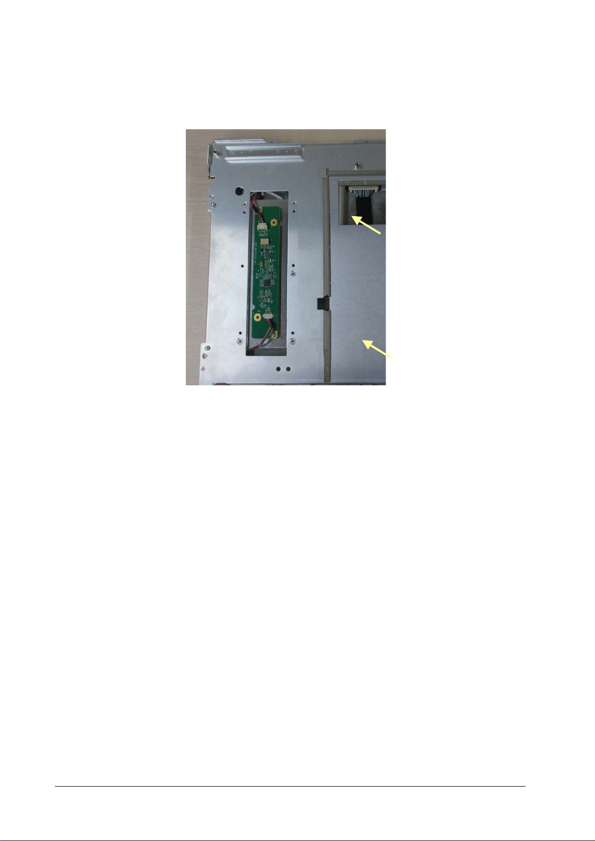
5.4.5 Removing the Backlight board
Unplug the cables from the button board and the LCD to the inverter. Then, remove the two M3×6 screws and
remove the backlight board.
5-8 Passport 17m Service Manual
Page 81
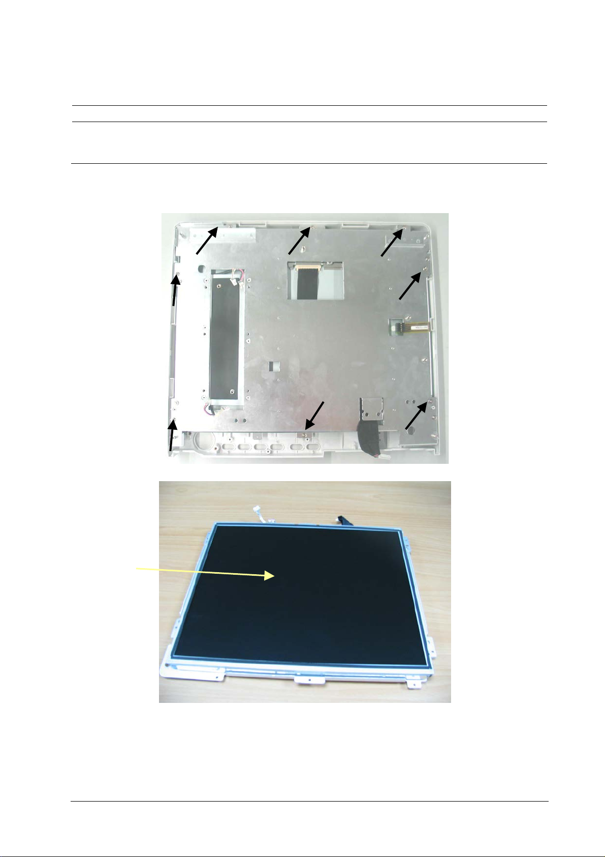
CAUTION
Do not touch the
LCD panel
5.4.6 Removing the LCD Screen
Do not touch the LCD screen.
Disassemble the LCD screen in an environment as dust-free as possible.
1. Carefully remove the eight M3×6 screws and take the screen assembly out. To prevent the screen from being
contaminated by dust, do not touch the screen.
Passport 17m Service Manual 5-9
Page 82
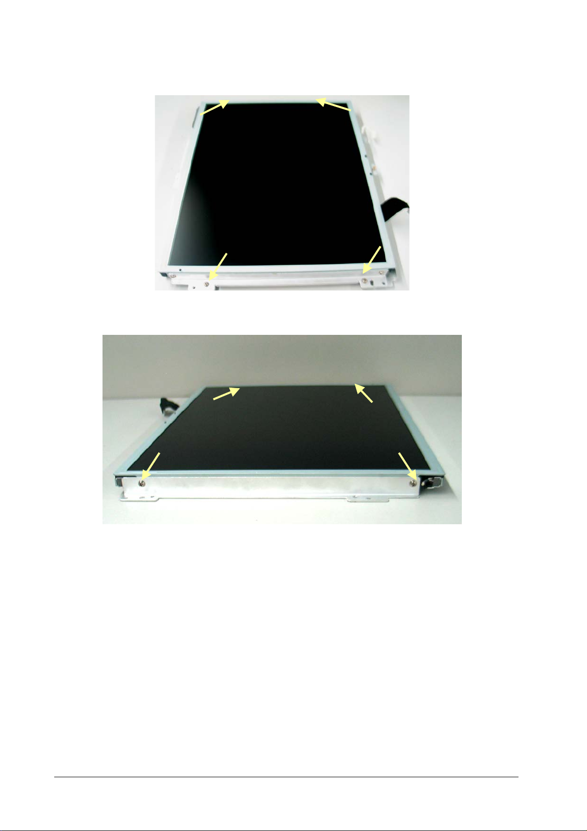
2. Remove the four M3×6 screws and take out the LCD screen.
3. Remove the four M3×6 screws and separate the LCD screen from the two supports.
5-10 Passport 17m Service Manual
Page 83
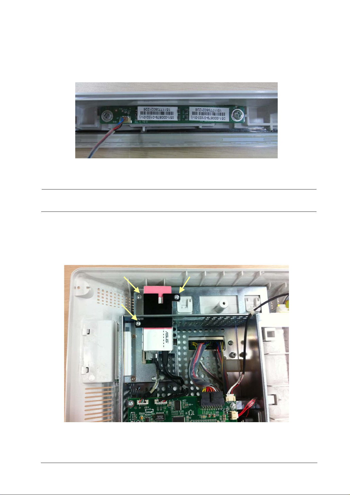
NOTE
5.4.7 Removing the Alarm Lamp Board
After removing the LCD panel, disconnect the cable that connects the alarm lamp board and the button board, and
then remove the two PT2×6 screws to remove the alarm lamp board.
Exercise care when removing the alarm lamp board because it may be adhered to the LCD assembly (as
shown in the above figure).
5.4.8 Removing the Wireless AP
1. Unplug the wireless AP cable from the main board. Remove the three M3×6 screws and take out the wireless AP
assembly.
Passport 17m Service Manual 5-11
Page 84
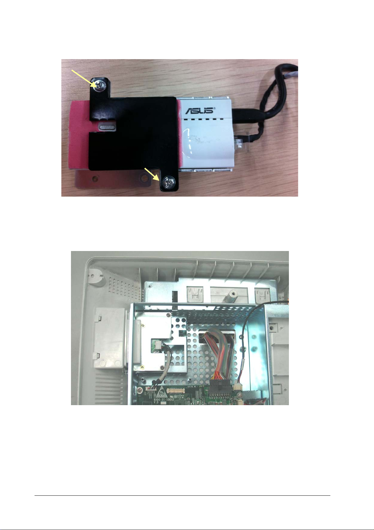
2. Remove the two M3×6 screws and then remove the wireless AP.
5.4.9 Removing the CF Assembly
1. Disconnect the cable between the CF driver board and main board. Remove the two M3×6 screws and take out
the CF assembly.
5-12 Passport 17m Service Manual
Page 85
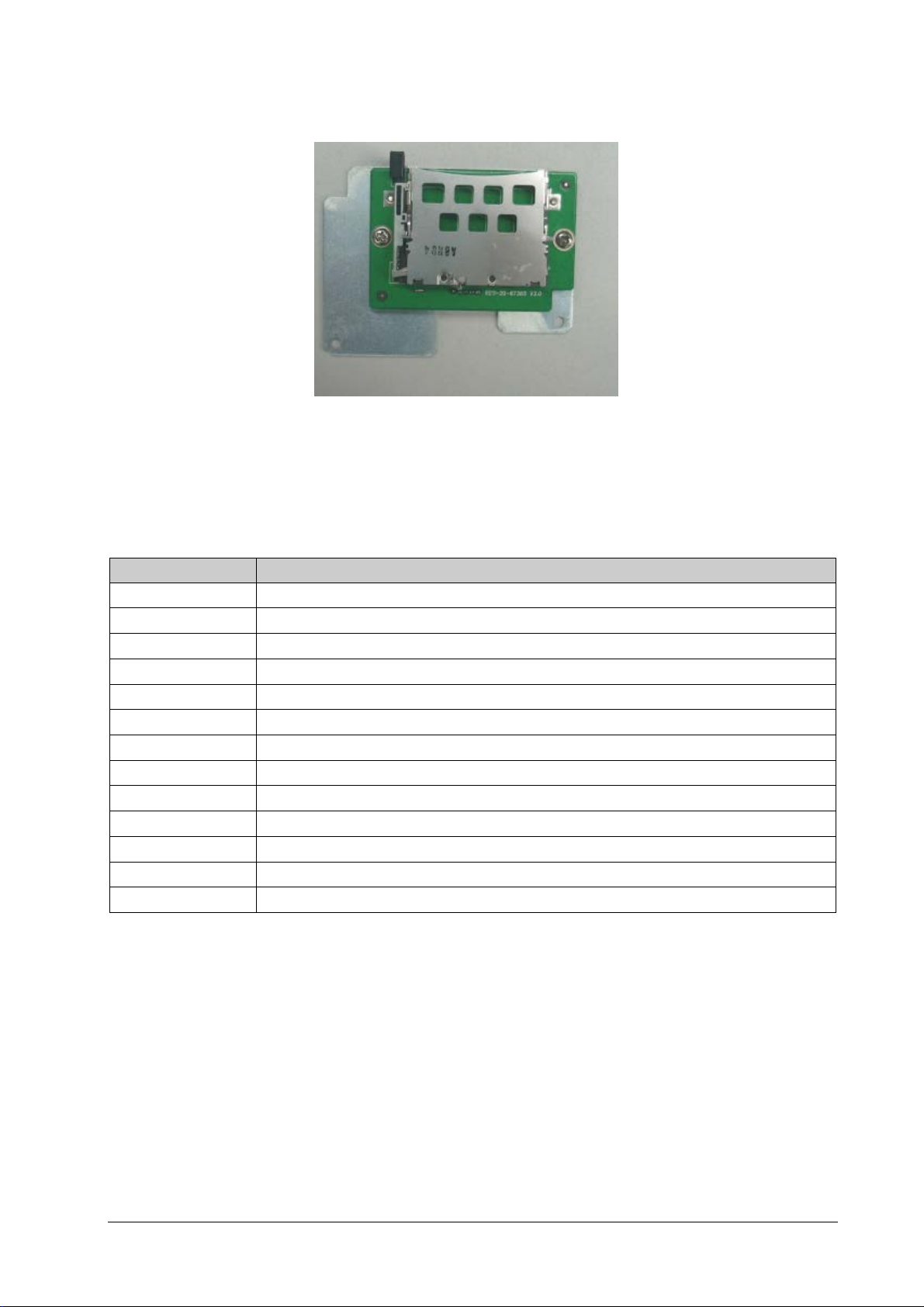
2. Remove the two M3×6 screws and take out the CF driver board.
5.4.10 Removing the Main Board
1. Pull out all the connectors on the mother board. There are numbers beside the connectors, which are listed
below.
Number Connected to
J1 Power module
J2 Speaker
J3 Fan
J4 Integral module rack
J5 Button board
J6 DVI interface board
J7 LCD panel
J8 Recorder
J16 Wireless AP
J10 iView assembly
J11 USB interface board
J12 CF assembly
J22/J23 CPU board, which is connected to the mother board with a socket
Passport 17m Service Manual 5-13
Page 86
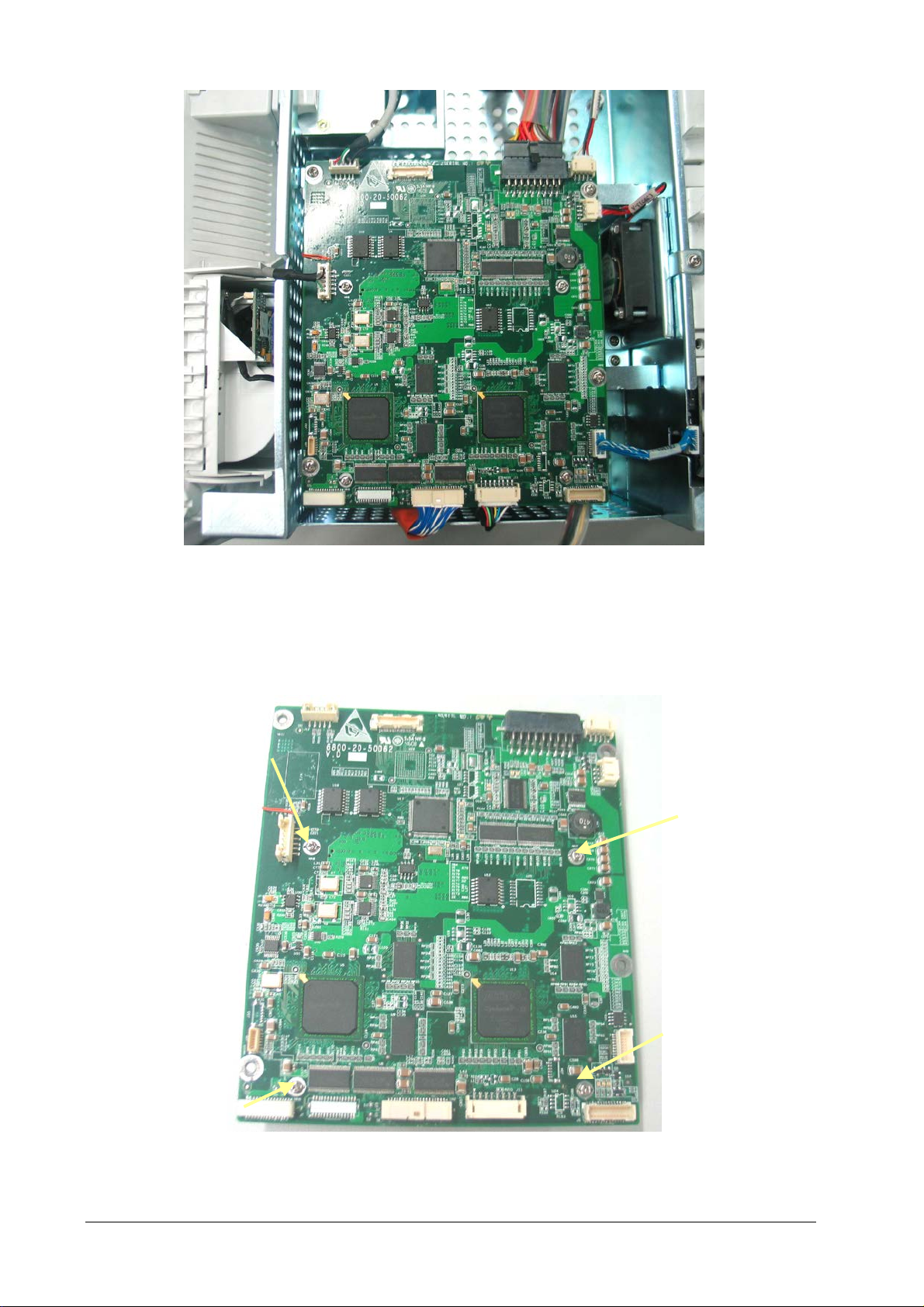
2. Remove the four M3×6 screws as shown in the figure below and take out the main board that includes the
mother board and the CPU board.
3. Remove the four M2.5×6 screws and separate the mother board from the CPU board. Be sure not to damage the
socket that connects the two boards. There is a battery on the CPU board.
5-14 Passport 17m Service Manual
Page 87
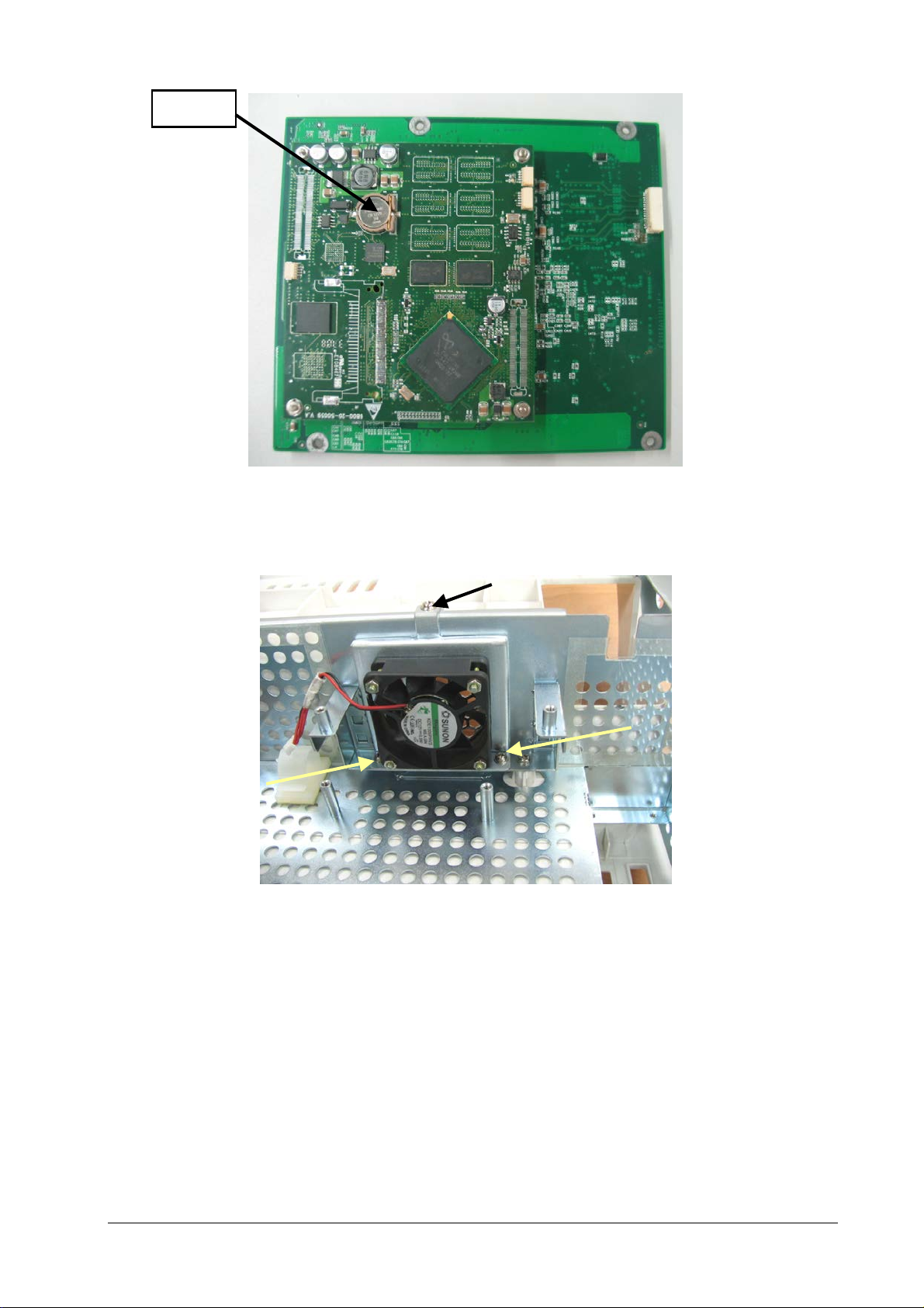
Battery
5.4.11 Removing the Fan
Unplug the fan connector from the mother board. Remove the three M3×6 screws and remove the fan.
Passport 17m Service Manual 5-15
Page 88
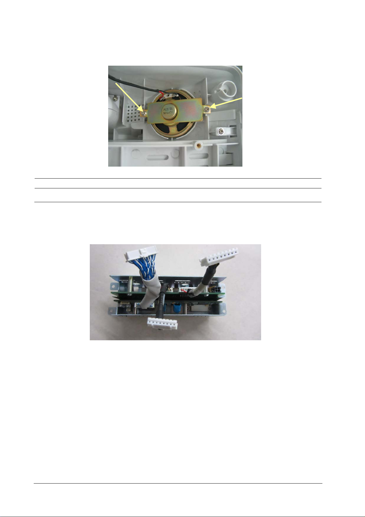
5.4.12 Removing the Speaker
Unplug the speaker connector from the mother board. Remove the two M3×6 screws and remove the speaker.
CAUTION
When installing a speaker, be sure to route the wires so they are not pinched during assembly.
5.4.13 Removing the Interface Board Assembly
1. Remove the four M3×6 screws and remove the interface board assembly.
5-16 Passport 17m Service Manual
Page 89
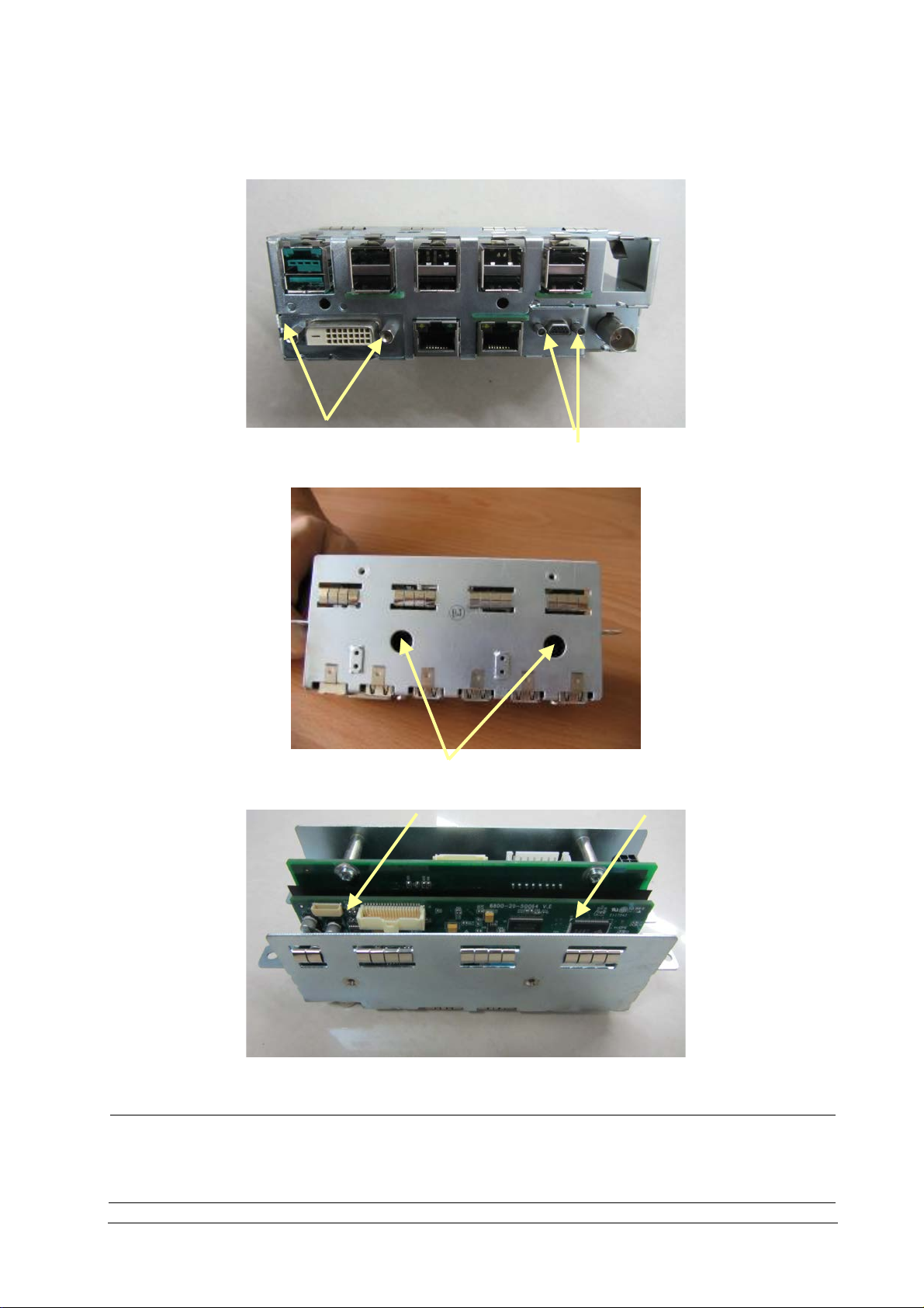
Screws beside DVI socket
Screws beside micro
Two M3
2. Remove the screws beside the DVI socket and micro-D socket. Then remove the two M3×6 screws in the holes.
You can then remove the DVI interface board.
-D socket
3. Remove the two M3×6 screws and take out the USB interface board.
×6 Screws in Holes
NOTE
The DVI interface board must be removed before the USB interface board.
Be careful not to damage the insulation between the DVI interface board and the USB interface board. If it
is damaged, replace it.
Passport 17m Service Manual 5-17
Page 90
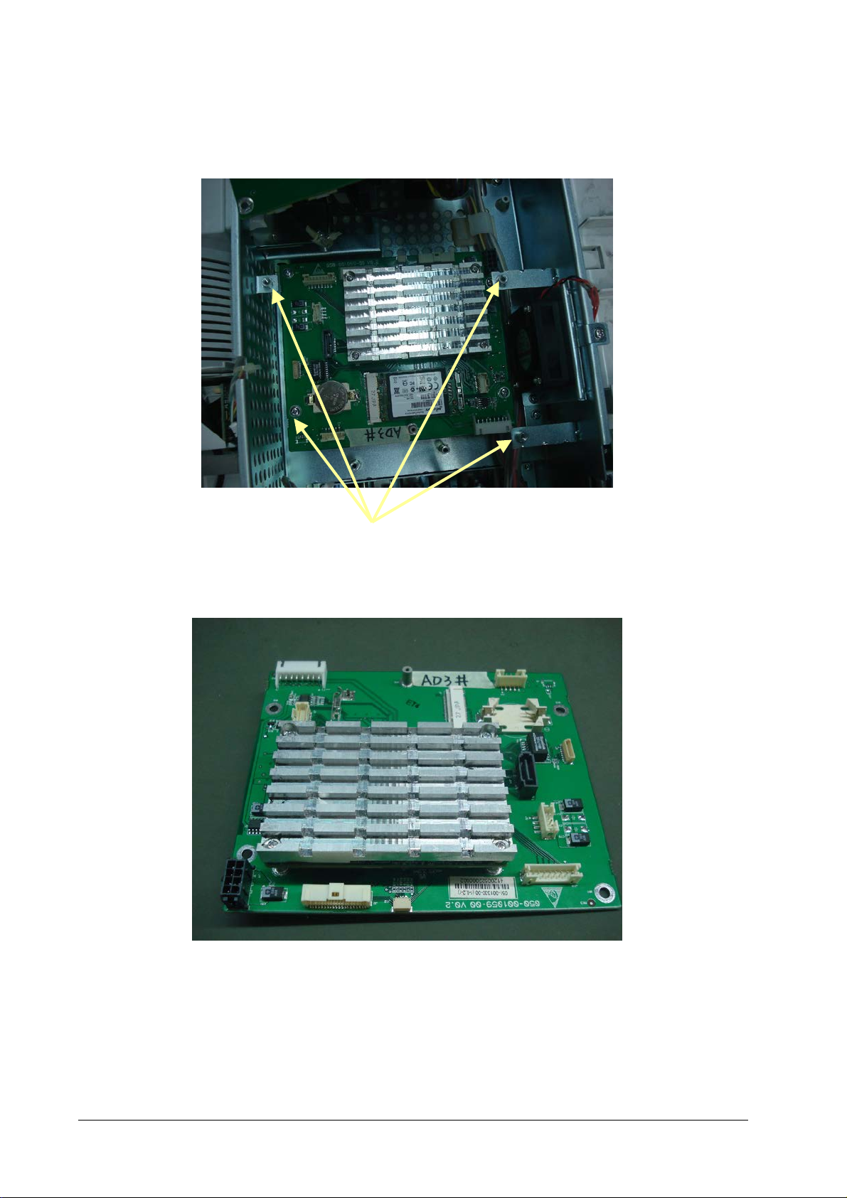
5.4.14 Removing the iView Assembly
1. Remove all the connecting cables between the iView mother board and power board, USB interface board,
mother board and the DVI interface board. Remove the four M3×6 screws, and remove the iView assembly.
2. Remove the SSD hard disk and battery from assembly
M3× 6 screws
5-18 Passport 17m Service Manual
Page 91
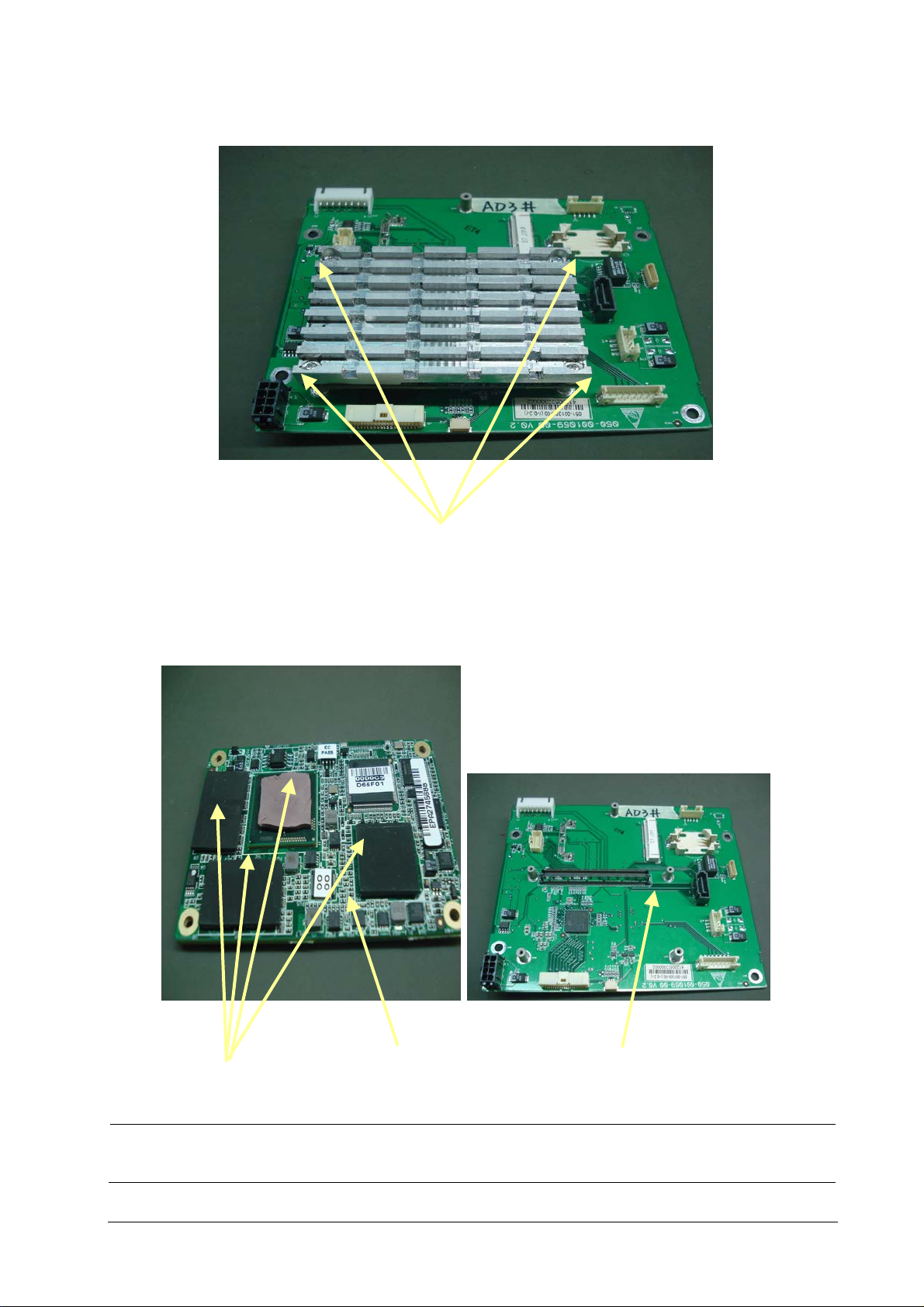
H
3. Remove the four Phillips pan head countersunk screws and remove the cooling fin in the industrial control board.
Phillips pan head countersunk screws
4. Separate industrial control board from mother board. Remove the heat conductive adhesive on the mother
board.
eat-conductive glue
Industrial control board
Mother board
NOTE
Make sure the heat-conductive adhesive is applied before reinstallation. Remember to install the
standoffs on the CIS mother board when reassembling.
Passport 17m Service Manual 5-19
Page 92
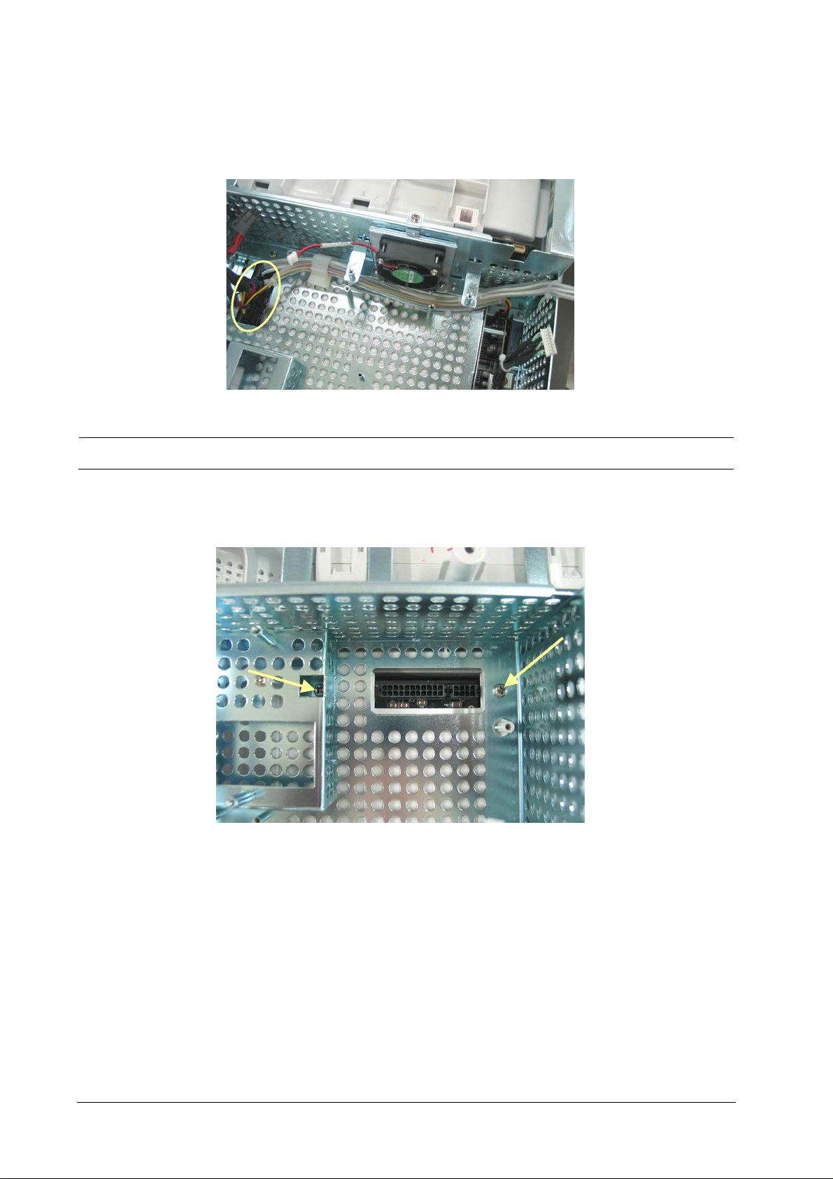
5.4.15 Removing the Power Supply Assembly
1. Disconnect the four cables coming from the main control board, the iView assembly, the DVI interface board and
the battery interface board. These are all connected to the power supply socket.
NOTE
For some cables, you have to release the clips before disconnecting them.
2. Remove the two M4×20 screws. Be sure to hold the power supply assembly to prevent it from falling when
removing these screws.
5-20 Passport 17m Service Manual
Page 93
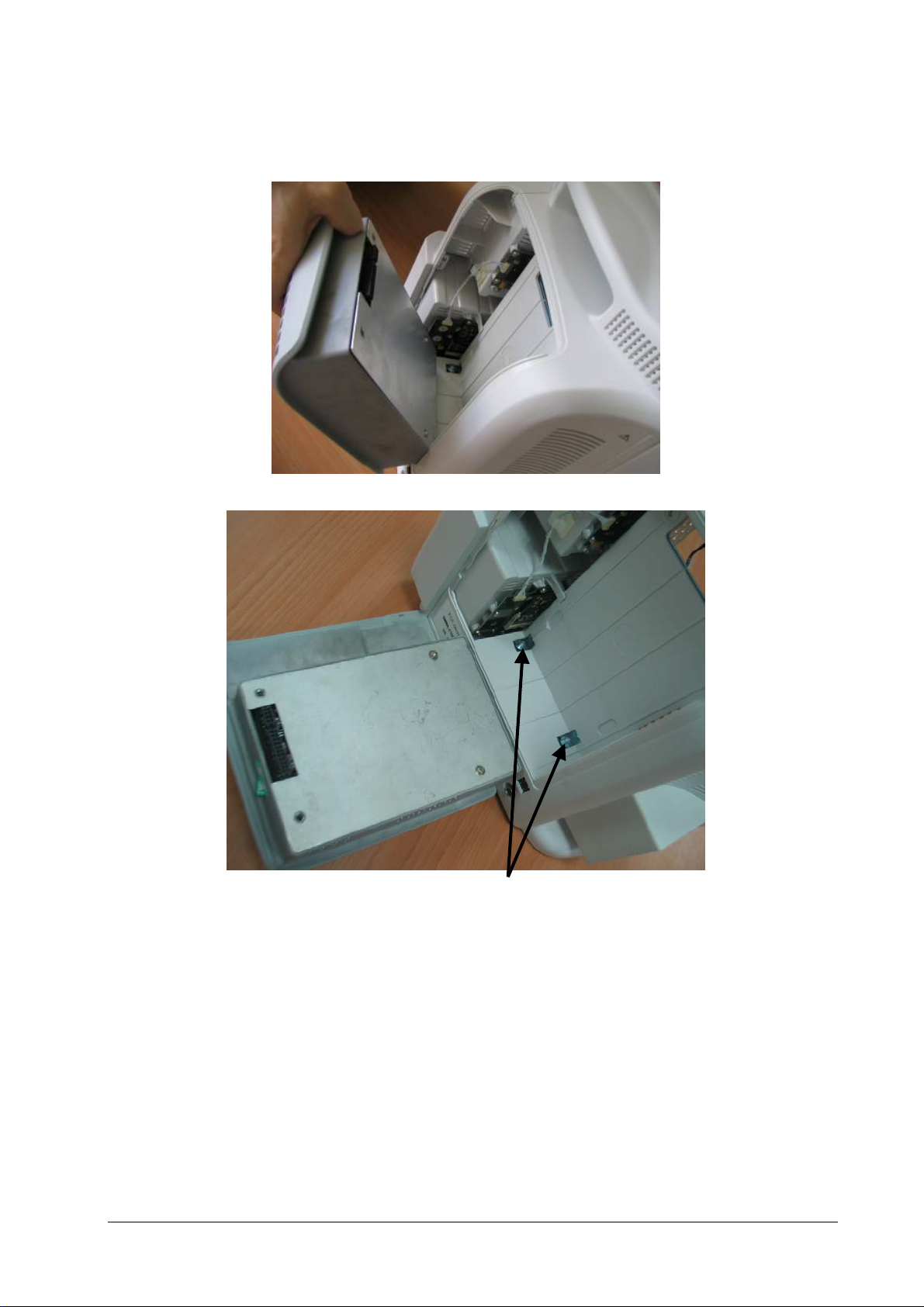
3. Lift the power supply assembly slightly to separate it from the two studs on the rear cover and then remove the
assembly.
Passport 17m Service Manual 5-21
Studs
Page 94
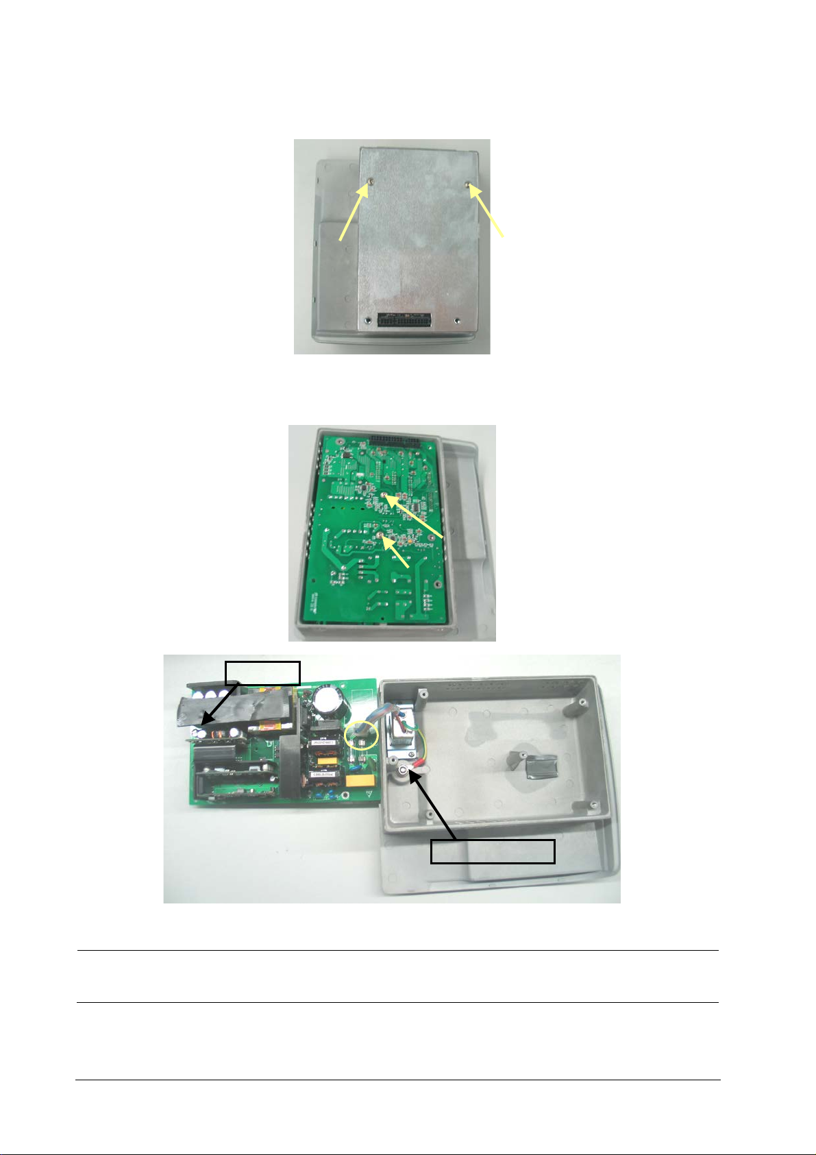
Insulator
Equipotential Pillar
4. Remove the two M3×12 screws and remove the power supply cover.
5. Remove the two M3×6 screws. Pry out the board with a small flat-bladed screwdriver in the gap between the
power supply board and the housing. Then turn the board over and unplug the cables from it.
NOTE
The power supply board may be stuck to the insulator, be careful not to damage the connector and cables
when separating the two.
5-22 Passport 17m Service Manual
Page 95
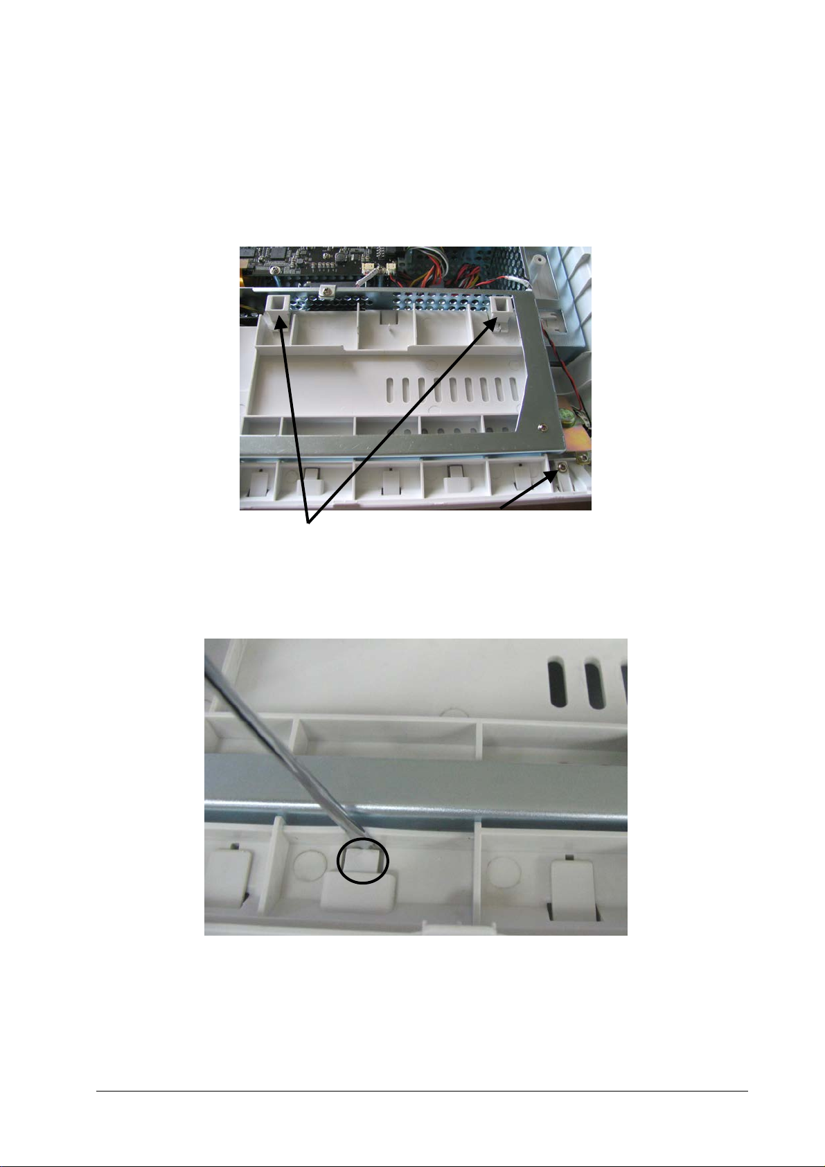
Bolts
5.4.16 Removing the Integral Module Rack
The following disassembly procedure uses the 3-slot module rack as an example. You can disassemble other size
module racks by referring to this procedure.
1. Disconnect the cable that connects the integral module rack with the mother board. Remove the two bolts and
then remove the M3×6 screw.
2. Pry the snaps out about 1mm away with a small flat-bladed screwdriver. Then insert the small flat-bladed
screwdriver into the position marked in the picture below and pry it out about 1mm so that the module rack
becomes disengaged from the back cover.
Passport 17m Service Manual 5-23
Page 96
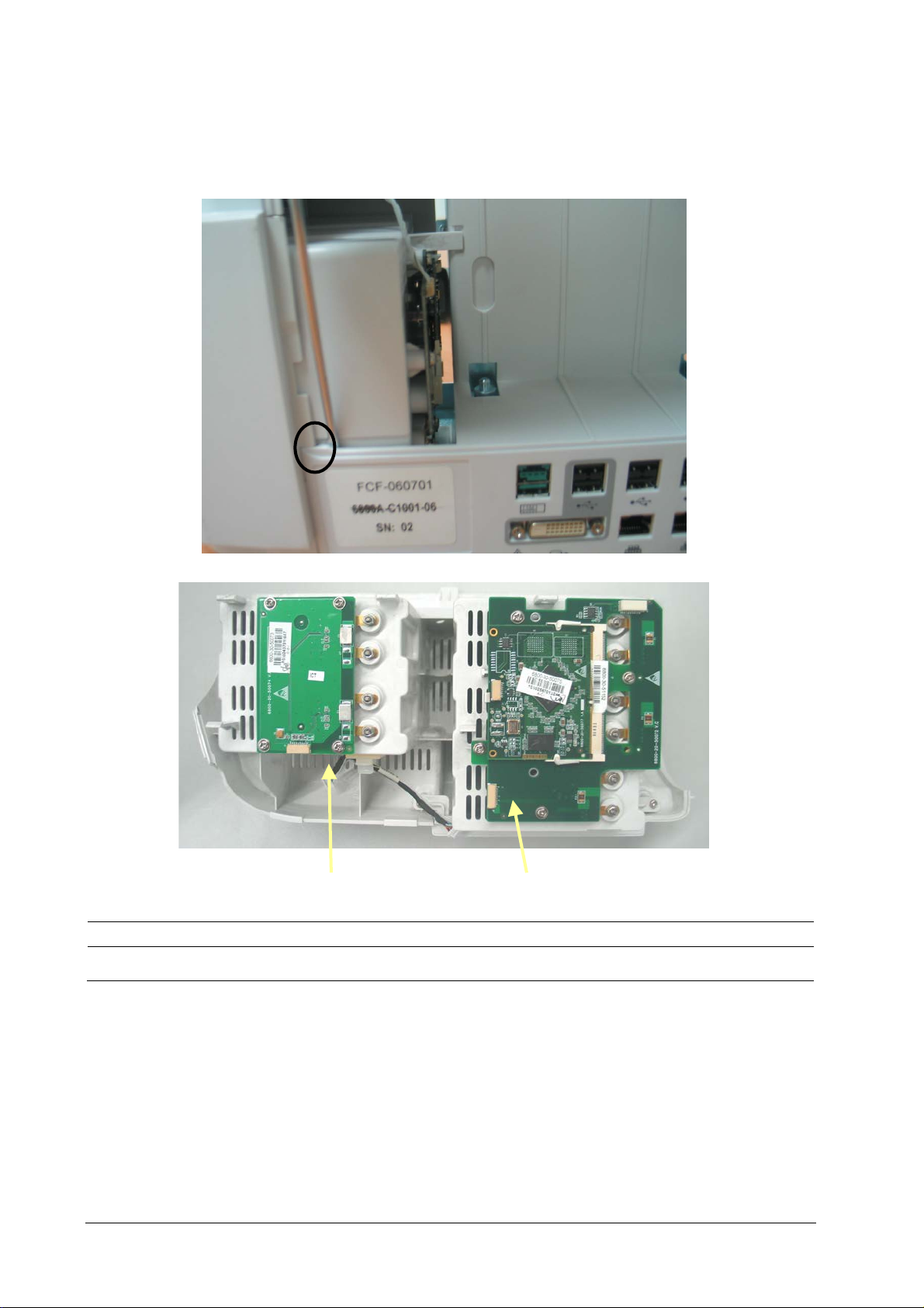
MPM Communication Board
3
3. If the module rack still engages with the back cover, insert a small flat-bladed screwdriver into the position
marked in the picture and pry it out about 1mm to release the hidden snap between the integral module rack
and the back cover. Then pull out the module rack.
-slot module Rack Communication Board
CAUTION
Be sure to release the hidden snaps first when removing the integral module rack.
5-24 Passport 17m Service Manual
Page 97

Nios II module
MPM Communicat
3
4. Release the three clips on the 3-slot module rack communication board and remove the Nios II module.
5. Remove the four M3×6 screws and take out the 3-slot module rack communication board. Remove the four M3
×6 screws and take out the MPM Communication Board.
ion Board
-slot module Rack Communication Board
Passport 17m Service Manual 5-25
Page 98
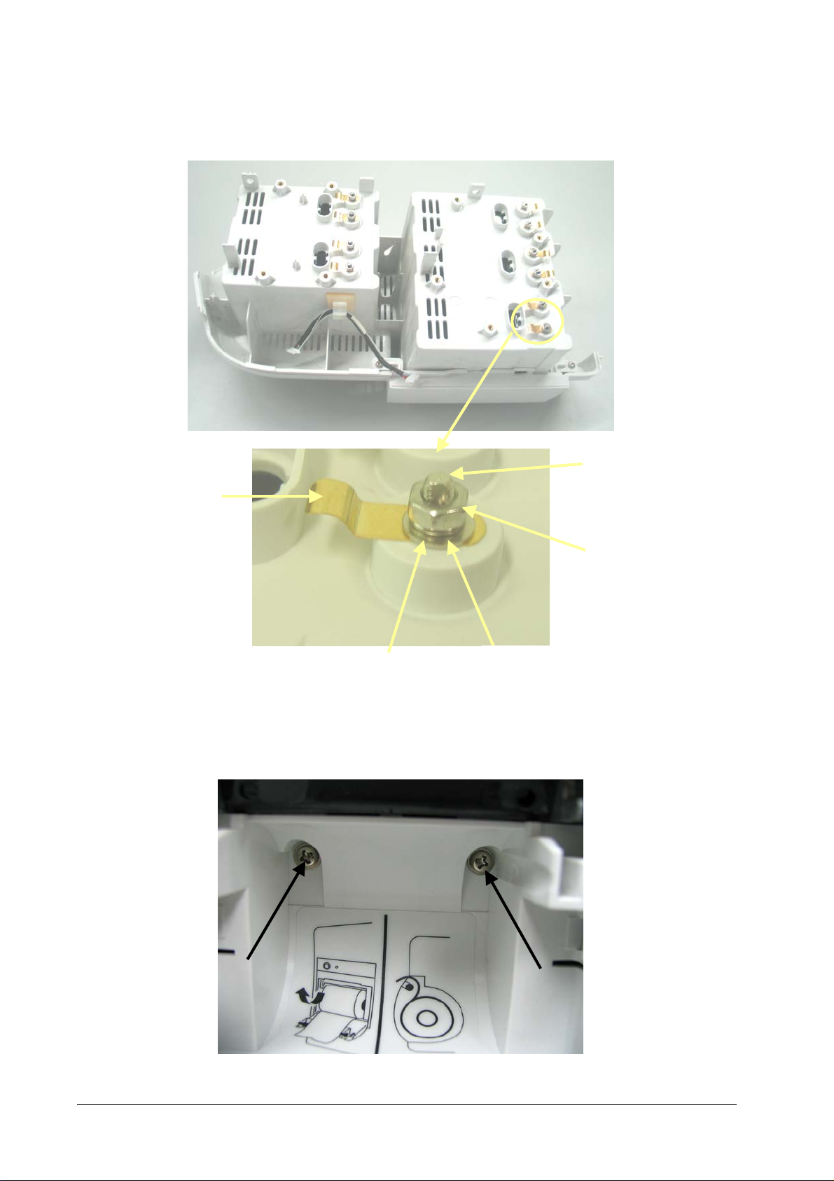
Contact screw
M3 nut
Leaf spring
M3
M3 flat washer
6. Remove the hex nut assy using the hex nut driver or socket wrench. Then separate the washer, leaf spring and
contact screw from each other.
5.4.17 Removing the Recorder
1. Open the recorder door and remove the two M3×6 screws.
split lock washer
5-26 Passport 17m Service Manual
Page 99
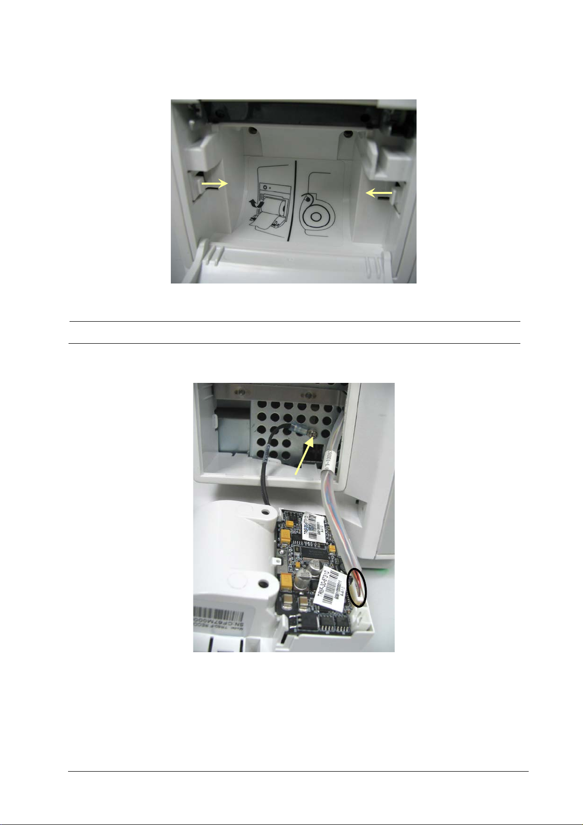
2. Pull the two clips in as indicated and simultaneously pull out the recorder.
NOTE
Be sure not to damage the connecting cables or connectors when pulling out the recorder.
3. Remove the M3×6 screw and remove the cables marked in the picture.
Passport 17m Service Manual 5-27
Page 100
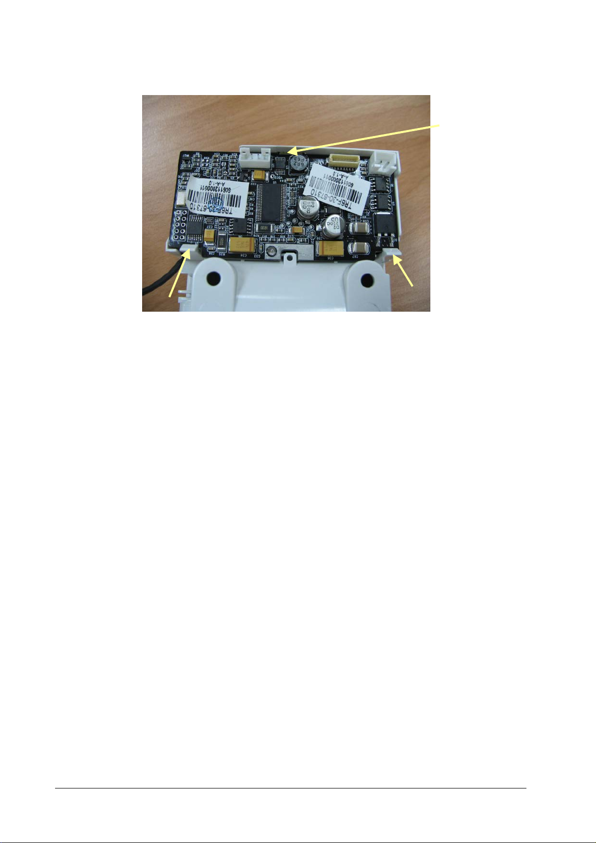
S
4. Release the two clips and take out the recorder drive board. Pay attention to the snap in the front.
nap
5-28 Passport 17m Service Manual
 Loading...