

Page 1
™
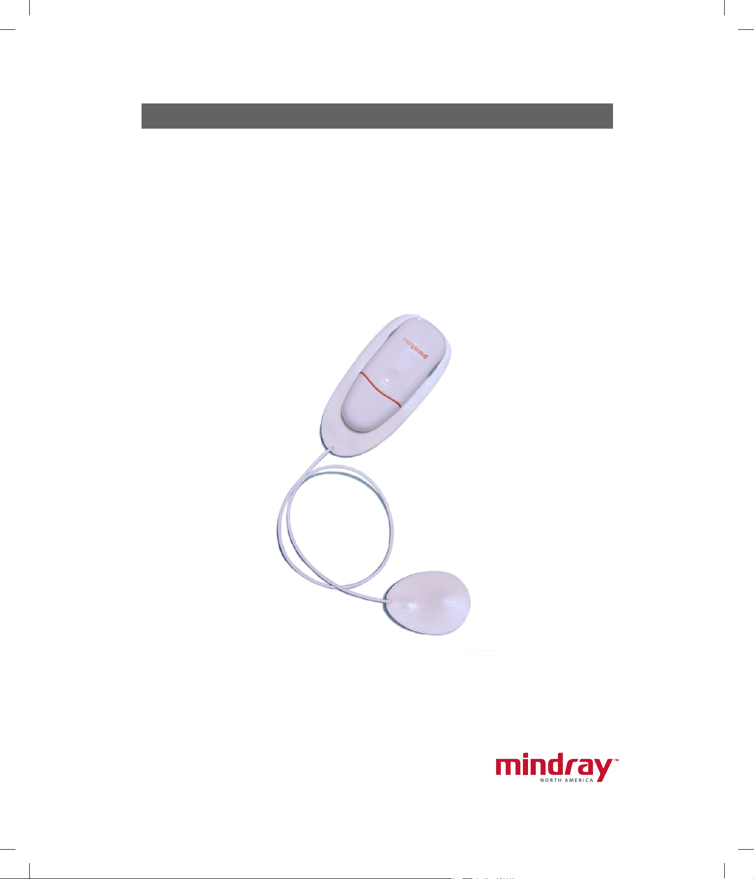
Datascope
NetGuard
Service Manual
0070-01-0685-01_revB.indd 1 3/10/10 5:23:19 PM
Page 2

™
Datascope
NetGuard
Service Manual
Page 3

NetGuard® is a U.S. registered trademark of Mindray DS USA, Inc.
©
Copyright
Mindray DS USA, Inc., 2009. All rights reserved. Contents of this publication may not be reproduced in any
form without permission of Mindray DS USA,Inc.
NetGuard Service Manual 0070-10-0685
Page 4

Table of Contents
Foreword....................................................................................................................................................... iii
Warnings, Cautions and Notes ........................................................................................................................iii
Instrument Description ...................................................................................................... 1 - 1
Introduction.................................................................................................................................................... 1 - 1
Overview....................................................................................................................................................... 1 - 1
Core Functions ............................................................................................................................................... 1 - 3
Connectivity ................................................................................................................................................... 1 - 3
Block Diagrams .............................................................................................................................................. 1 - 3
System Modules and Components..................................................................................................................... 1 - 4
Patient Worn Device ................................................................................................................................ 1 - 4
Access Points .......................................................................................................................................... 1 - 4
NetGuard Access Point Switch .................................................................................................................. 1 - 4
NetGuard Server Application.................................................................................................................... 1 - 4
NetGuard Client Application .................................................................................................................... 1 - 4
Repair Information ........................................................................................................... 2 - 1
Introduction.................................................................................................................................................... 2 - 1
Safety Precautions ................................................................................................................................... 2 - 1
Equipment and Special Tools Required....................................................................................................... 2 - 1
Troubleshooting .............................................................................................................................................. 2 - 2
Installing the Server Software .................................................................................................................... 2 - 5
Installing the Client PC Software ................................................................................................................ 2 - 7
Programming the Access Points ................................................................................................................. 2 - 10
Telnet Instruction...................................................................................................................................... 2 - 11
Program Instructions................................................................................................................................. 2 - 12
Troubleshooting .............................................................................................................................. 2 - 17
Configurations ................................................................................................................................ 2 - 17
Replacement Parts ............................................................................................................ 3 - 1
System Requirements and Specifications ........................................................................... 4 - 1
Server - Minimum Requirements ........................................................................................................................ 4 - 1
Hardware............................................................................................................................................... 4 - 1
Software................................................................................................................................................. 4 - 1
Switch - Minimum Requirements ........................................................................................................................ 4 - 2
Client PC - Minimum Requirements .................................................................................................................... 4 - 2
PC Hardware.......................................................................................................................................... 4 - 2
PC Software............................................................................................................................................ 4 - 2
Mounting Rack (if applicable)........................................................................................................................... 4 - 2
Cabling ......................................................................................................................................................... 4 - 2
Cable Connectors ........................................................................................................................................... 4 - 2
Power Requirements ........................................................................................................................................ 4 - 2
Agency Compliance........................................................................................................................................ 4 - 3
NetGuard Service Manual 0070-10-0685 i
Page 5

Table of Contents
ii 0070-10-0685 NetGuard Service Manual
Page 6

Foreword Introduction
Foreword
The NetGuard Service Manual is a guide for technically-qualified personnel who perform
maintenance and /or repair on the NetGuard System.
The Service Manual conveys system-wide information that is divided into sections. For quick
reference, each chapter’s title page displays a table of contents that indicates sectionally, the
topics covered.
This publication may have been updated to reflect product design changes and/or manual
improvements.
NOTE: Unauthorized servicing may void the remainder of the
warranty. Check with the factory or with a local authorized
Mindray DS representative to determine the warranty status
of a particular instrument.
Warnings, Cautions and Notes
Please read and adhere to all warnings, precautions and notes listed here and in the
appropriate areas throughout this manual.
A WARNING is provided to alert the user to potential serious outcomes (death, injury, or
serious adverse events) to the patient or the user.
A CAUTION is provided to alert the user to use special care necessary for the safe and
effective use of the device. They may include actions to be taken to avoid effects on patients
or users that may not be potentially life threatening or result in serious injury, but about which
the user should be aware. Cautions are also provided to alert the user to adverse effects on
this device of use or misuse and the care necessary to avoid such effects.
A NOTE is provided when additional general information is applicable.
NetGuard Service Manual 0070-10-0685 iii
Page 7

Introduction Warnings, Cautions and Notes
Warnings
WARNING: Only qualified and trained Mindray DS Patient Monitoring
Service personnel or those trained by Mindray DS Patient
Monitoring Service should attempt to service this equipment.
Service is defined as any activity requiring the cover to be
removed for internal adjustments, parts replacements,
repairs or software upgrades of any kind to ensure
compatibility.
WARNING: To ensure compatibility with the operating system and
applications software, use only Mindray DS USA, Inc.
supplied and/or approved components to repair any part of
the NetGuard
devices, accessories, or cables other than those approved by
Mindray DS USA, Inc. may render the application unsuitable
for medical patient monitoring. It may also result in
increased electromagnetic emissions or decreased Immunity
of the system.
WARNING: To adequately display the software application, it is
important to maintain a minimum screen resolution of
1024x768 with 96 dpi.
™
System. Use of unauthorized software,
WARNING: Some of the equipment on the NetGuard Network must
utilize the hospital emergency power system. Failure to do
so will result in loss of monitoring during extended periods
of power failure. The back-up power time period for the
NetGuard Network is limited.
WARNING: Changes to the NetGuard server configuration and client PC
software should not be performed without the guidance of
a qualified service representative.
WARNING: Do not use the NetGuard device in an explosive atmosphere
or in the presence of flammable anesthetics or gases.
Cautions
CAUTION: For proper operation use with UL agency approved ethernet
cables.
CAUTION: For proper operation, do not use the equipment with a
frayed or damaged power cord or ethernet cable.
CAUTION: Do not use a damaged or broken unit or accessory.
CAUTION: For proper operation never place fluids on top of the server.
In case of accidental spillage, remove power, wipe clean
immediately and have the system serviced to ensure no
hazard exists.
CAUTION: The server and client PC for this device must only be setup
by qualified service personnel.
CAUTION: Do not block the client PC’s speakers. Set the volume levels
to ensure that alarms can always be heard.
CAUTION: Speaker volume should be set high enough to hear an
alarm above ambient noises.
iv 0070-10-0685 NetGuard Service Manual
Page 8

CAUTION: To avoid possible interference with other facility devices, use
the correct AC cord for all equipment installed on the
NetGuard network.
CAUTION: It is recommended that password protected screen savers
be disabled after the NetGuard client PC software
installation. Use of screen savers may degrade the
performance of NetGuard software application.
®
CAUTION: It is recommended that the Microsoft
Windows power
management features such as power save or hibernation be
disabled after the NetGuard client-side software
installation.
NetGuard Service Manual 0070-10-0685 v
Page 9

This page intentionally left blank.
vi 0070-10-0685 NetGuard Service Manual
Page 10

1.0
Instrument Description
1.1 Introduction
This section of the service manual provides an overview of the NetGuard System, followed
by more detailed information.
1.2 Overview
The NetGuard System is an ambulatory monitoring system that issues alerts automatically to
clinicians when it recognizes potentially life-threatening cardiac rhythms in monitored
patients. The system monitors patient ECG and heart rate and issues alerts whenever specific
arrhythmias are detected or the measured values deviate from acceptable ranges.
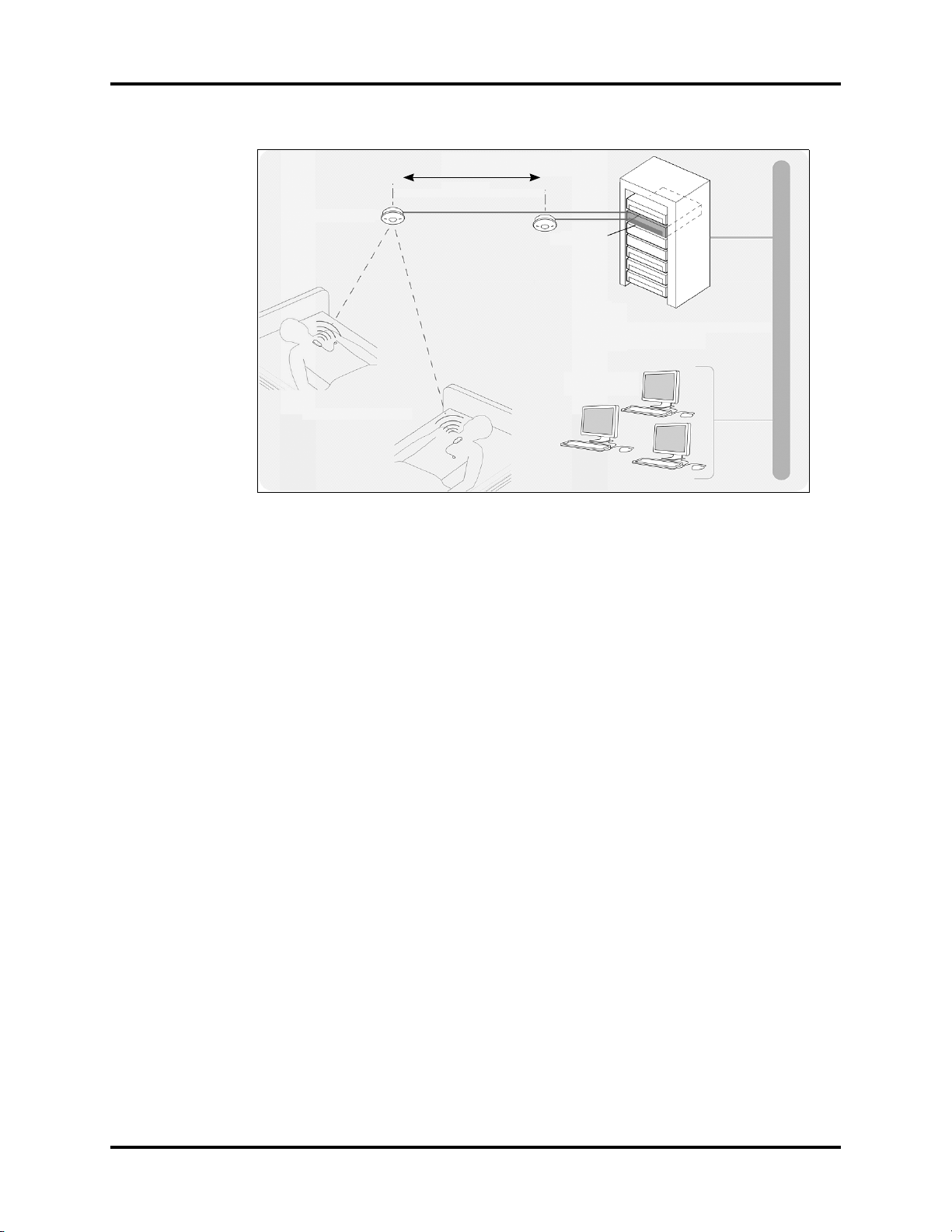
The NetGuard System (shown in FIGURE 1-1) consists of the NetGuard devices, a wireless
infrastructure, a central server, one or more client PCs, and proprietary software running on
the server and client PCs.
The server application collects patient data from the reusable device via ceiling or wall
mounted access points. This allows patients to move within the designated areas of the
hospital. The NetGuard wireless network is based on ZigBee protocol (802.15.4) which
operates in the 2.4 GHz band.
NetGuard Service Manual 0070-10-0685 1 - 1
Page 11
Overview Instrument Description
max = 60ft
NetGuard Access
Point
NetGuard Server
Hospital Backbone
Patients wearing
NetGuard Devices
Client PCs
FIGURE 1-1 NetGuard System Overview
1 - 2 0070-10-0685 NetGuard Service Manual
Page 12
Instrument Description Core Functions
1.3 Core Functions
The NetGuard client application displays, records, and recalls patient ECG data (i.e., heart
rate, and waveforms). At installation of the system, the following items are setup:
• User Management
• Room Management
• Monitor Group Management
• Alarm Management
• Database Management
• Network / Device Management
In the event of a Lethal System level alarm, a hospital staff member must see the patient to
silence the alarm. All other alarms, such as System level heart rate alarms and Technical
alarms can be silenced at the NetGuard client application.
1.4 Connectivity
The reusable device is powered when connected to the disposable electrode. Cardiac
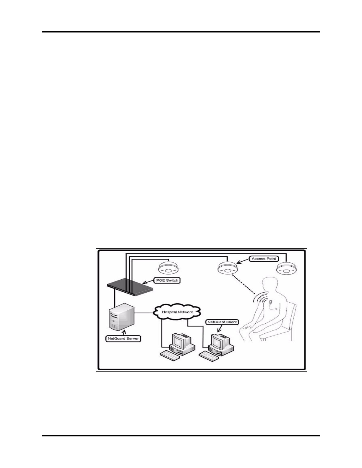
signals and device status are transmitted wirelessly to access points. The access points are
connected via Ethernet cabling to the network switch, and a server. Patient data is processed,
and sent to the NetGuard client application.
1.5 Block Diagrams
FIGURE 1-2
NetGuard Service Manual 0070-10-0685 1 - 3
Page 13

System Modules and Components Instrument Description
1.6 System Modules and Components
1.6.1 Patient Worn Device
The patient worn device consists of two components: a disposable electrode and reusable
transmitter. The disposable consists of a lead wire set, a coin cell battery, and a receptacle
for the reusable. The reusable analyzes the ECG data from the disposable and transmits it
wirelessly to the access points.
1.6.2 Access Points
Access points route data between the patient worn device and the server. The reception
range of the access point is dependent on the surrounding environment (e.g., wall
construction, etc.) and is determined during the site survey.
1.6.3 NetGuard Access Point Switch
The switch connects and powers (PoE) the access points to the NetGuard server and the
hospital network.
1.6.4 NetGuard Server Application
The server application receives data from the patient worn devices and stores it in the patient
database. This application also distributes the data from the database to the client
application.
1.6.5 NetGuard Client Application
The client application runs on designated PCs and supports the following:
• Patient admission and discharge from the system
• Displays alarms and patient heart rate data
• Prints reports and other patient related information
1 - 4 0070-10-0685 NetGuard Service Manual
Page 14

2.0
Repair Information
2.1 Introduction
This section provides the necessary technical information to perform repairs to the NetGuard
System. The most important prerequisites for effective troubleshooting are a thorough
understanding of the system functions. If necessary, refer to the NetGuard Operating
Instructions (P/N 0070-00-0678-XX), which describes instrument functions and features in full
detail.
2.1.1 Safety Precautions
If any of the instrument covers are removed, make certain to observe the proper anti-static
precautions.
2.1.2 Equipment and Special Tools Required
When performing system repairs, the following special tools may be needed:
• Laptop Computer
• Test Device Setup
• Bootstrap Loader
• CAT5E Cable Tester
• PoE Tester
• Wi-Fi Packet Analyzer
NetGuard Service Manual 0070-10-0685 2 - 1
Page 15

Troubleshooting Repair Information
Since no repairs are performed to the access points or reusables, other than reprogramming,
the previously listed tools can determine the location of the faulty components.
Only trained personnel are responsible for the service of equipment purchased from Mindray
DS USA, Inc. If opening the server is necessary, power it down and vacuum any
accumulated dust around the fan blades before opening it.
NOTE: The hospital is responsible for maintaining their network
components.
2.2 Troubleshooting
Separate the NetGuard components into the following sections:
1. Patient worn devices
2. Access Points
3. Network Rack Components
4. Client PC(s)
During the NetGuard installation process, an NetGuard Installation Verification Document
was completed listing all the MAC addresses, IP addresses, Subnet Mask addresses assigned
to the access points, server, and client PC(s). Always have a copy available for reference. If
a copy is not available, contact a service representative or authorized distributor that
installed the system.
Prior to troubleshooting a network problem, verify the following areas:
• Review Site Survey documentation
• All AC and DC power connections are secure.
• All Ethernet cable connections are secure. Verify connection and communication LEDs on
the switch. Affected cable runs could be tested with a cable tester for continuity.
• IP addresses for the server and client application
• Equipment assignment for the patient devices at the NetGuard client application
• Refer to diagram in the NetGuard Customer Installation Guide (P/N 0070-00-0686) for
LED status.
• View server or PC logs
ISSUE COMMENTS SOLUTION
ACCESS POINTS
Access point LEDs not illuminated In order for the amber LEDs to illuminate,
the green LEDs must be illuminated as they
indicate power and are on solid. One of
the flashing amber LEDs indicates
communication with the reusable. The other
flashing amber LED indicates connection to
the network. The reusable device Status
LED is amber.
Check the switch for the related port
and re-seat the cable connector.
Check the switch LED for that port to
see if the connection is recognized
and is communicating. If not, try a
different port or reboot the switch.
2 - 2 0070-10-0685 NetGuard Service Manual
Page 16

Repair Information Troubleshooting
ISSUE COMMENTS SOLUTION
Verify the switch is a Power over
Ethernet (PoE) switch and that it
meets the 802.3af standard.
Re-seat the connector of the cable at
the access point.
Test the cable with a cable tester.
Replace the access point (refer to the
NetGuard Service Installation Guide
P/N 0070-00-0687).
No communication between the
access point and reusable device
REUSABLE DEVICE
The reusable device Status LED flashes
amber.
Verify the LEDs on the access point(s)
are illuminated.
Verify that the reusable device is
entered into the Administrative Web
Site by device label and MAC
address
Check if there are other reusables
connected to the access point and
that they are functioning. Also verify
that the number of reusables
reporting to the access point does not
exceed 20 device limit. Refer to the
NetGuard Service Installation Guide
P/N 0070-00-0687).
Check that there is sufficient battery
power to the reusable.
Reprogram the device.
Replace the access point.
Refer to the NetGuard Operating
Instructions (P/N 0070-00-0678-XX)
for the power-up sequence.
Cannot enter the device to the
Administrative Web Site
The device cannot detect a heart
rate.
No communication between the
reusable and the network.
NetGuard Service Manual 0070-10-0685 2 - 3
The reusable may not be programmed. Program the reusable.
The Patient LED flashes yellow/amber. Verify the disposable placement
connection.
Remove the reusable and re-seat in
disposable.
Replace the reusable.
Replace the disposable and try the
reusable again.
The Status LED flashes yellow/amber. Verify the green access point LEDs
are illuminated.
Page 17

Troubleshooting Repair Information
ISSUE COMMENTS SOLUTION
Verify that the reusable device is
entered into the Administrative Web
Site by device label and MAC
address, and entered correctly. Refer
to NetGuard Service Installation
Guide, P/N 0070-00-0687).
Verify that there are other reusable
devices connected to the access point
and that they are functioning.
Verify that the number of reusable
devices reporting to the access point
does not exceed the 20 device
maximum.
Reprogram the device.
Replace the device.
The Status LED is on solid yellow/
amber.
NETWORK RACK
COMPONENTS
Access point switch indicators are
not illuminated and the access points
LEDs are not illuminated
SERVER
Client PC states that it cannot
communicate with server
There is insufficient power for the device. Re-seat or replace reusable device
Failed Power On Self Test (POST) Re-seat or replace reusable device
Verify the switch is a PoE switch and
follows the 802.3af standard.
Verify power to the switch
Test Ethernet cable
Recycle power to the switch.
Verify the server has not been
restarted and sitting at the DOS
prompt. If so, select F1.
Check the Error Logs by opening the
C:\Documents and Settings\All User
s\Application Data\Datascope\Logs
\wdrs_debug.txt file.
The message “Page cannot be
found.” displays.
CLIENT PC
2 - 4 0070-10-0685 NetGuard Service Manual
The IIS is not available. Load the IIS by doing the following:
Select Start > All Programs >
Administrative Tools > Services > IIS
Admin Service. Select Restart, then
select Yes.
Page 18

Repair Information Troubleshooting
ISSUE COMMENTS SOLUTION
NetGuard software will not install. Verify the PC meets minimum
NetGuard client application is
unresponsive or runs slowly
Cannot perform "ECG Request" Go to the Administrative Web Site
Communication Error message in
lower right corner of display.
requirements. Refer to the System
Requirements and Specifications
chapter.
Note the specific error message and
contact technical support.
Verify the PC meets minimum
requirements. Refer to the System
Requirements and Specifications
chapter.
Verify the network meets
requirements. Refer to the System
Requirements and Specifications
chapter.
Shut down other programs.
and verify the access point IP address
was entered correctly.
Verify that the PC is connected to the
switch, the switch is connected to the
server, and the switch/server is
turned on.
Check the switch LEDs to verify the
corresponding ports are illuminated.
2.2.1 Installing the Server Software
1. Verify or set the IP address and subnet mask on the server.
NOTE: Note these addresses on the Installation Verification
2. Set the Windows Update according to hospital procedure.
3. Load the NetGuard Server software onto the server following all the steps of the install
wizard:
a. Load the NetGuard Server software CD.
b. Go to My Computer and double-click on the respective drive.
c. Run Setup.exe from the NetGuard Server install folder.
d. Follow the default prompts and selections except on the Database Server dialog.
Document.
• On the Database Server field, change (local) to the server name.
• Verify that Windows authentication is selected.
NetGuard Service Manual 0070-10-0685 2 - 5
Page 19

Troubleshooting Repair Information
NOTE: If software is being loaded for the first time, leave "Create
Database" checked. If updating the software to a new
revision, uncheck "Create Database".
e. When the installer finishes, select the option Yes, I want to restart my
computer now.
f. Enter a reason for the shut down.
NOTE: The system will not shut down until a reason is entered.
g. After the reboot, close the Manage Your Server dialog, if it displays.
4. After the server installation, connect the CAT5e patch cable between the server and the
switch.
5. Verify the LED on the switch illuminates/flashes for that port.
6. Telnet to each access point and set/verify the following:
• Firmware revision is correct
• MAC address matches the documentation
• IP address
• Subnet mask
NOTE: Remain in Telnet to change any of the parameters. Refer to
the Telnet section of this manual.
7. Enter the Configuration files on the server by navigating to the following:
C:\Program Files\Datascope Corp\WDRS\WDRS.exe.config
a. Verify the Alarm Delay is set at 15. If not, delete the number listed and enter 15.
b. Save the file.
Connect your PC to the network switch (change PC IP address to match the server IP address
scheme) and ping the server IP address.
2 - 6 0070-10-0685 NetGuard Service Manual
Page 20
Repair Information Troubleshooting
2.2.2 Installing the Client PC Software
NOTE: Prior to installing the program, save and close all open
NOTE: Prior to installing the program, close all open applications.
applications.
1. Load the CD into the PC’s CD drive.
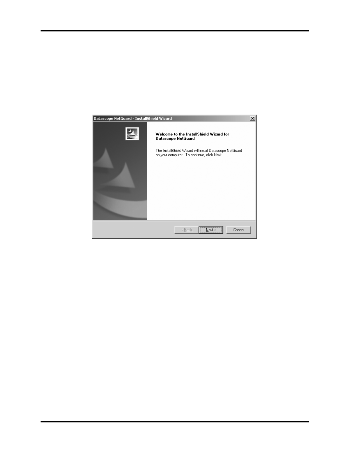
2. Double-click the Monitor.exe file to open the InstallShield Wizard.
FIGURE 2-1 InstallShield Wizard
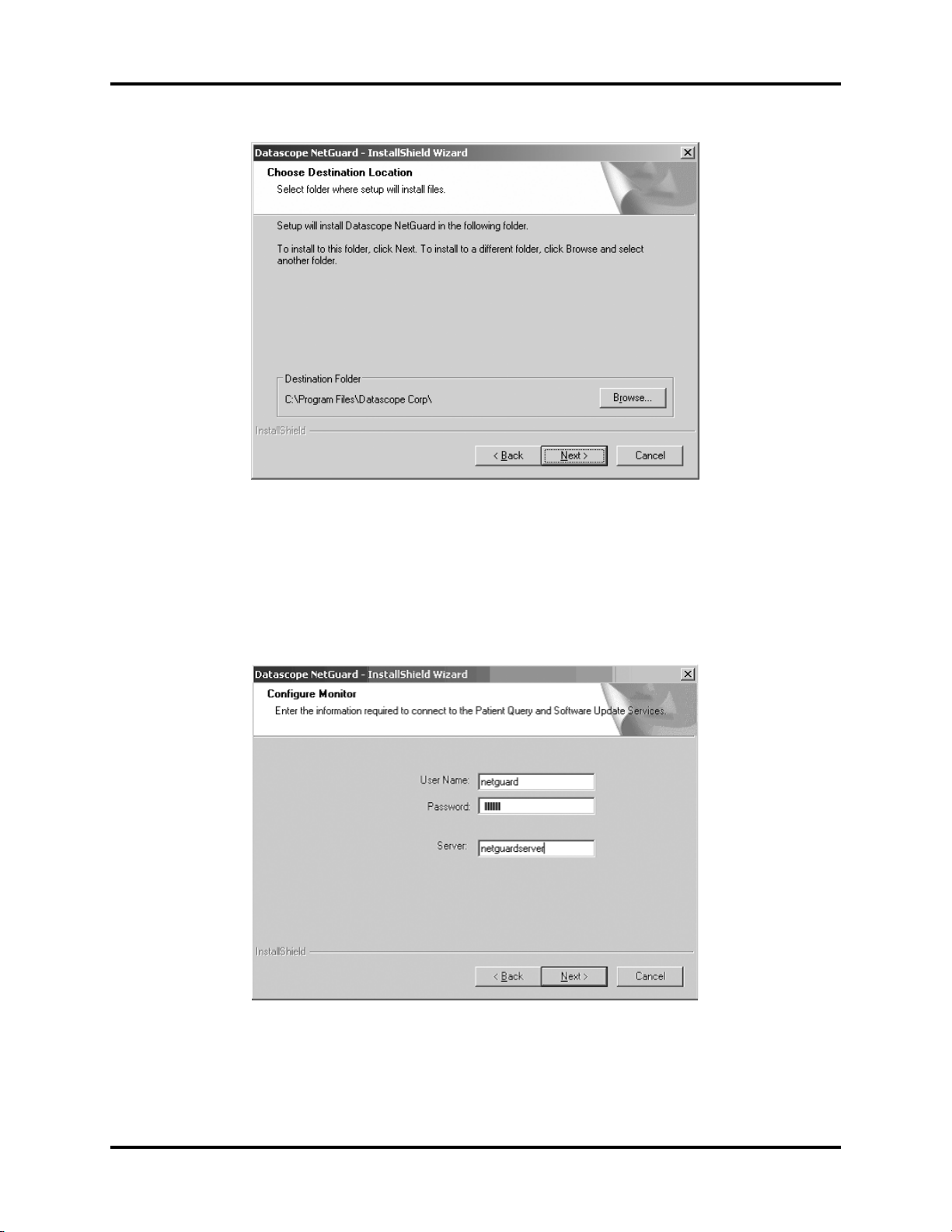
3. Select Next to open the Choose Destination Location dialog box. The InstallShield
Wizard automatically selects a destination folder on the PC.
• Optional - select Browse to change the destination folder.
•Select Next. The Configure Monitor window opens.
NetGuard Service Manual 0070-10-0685 2 - 7
Page 21
Troubleshooting Repair Information
FIGURE 2-2 Choose Destination Location
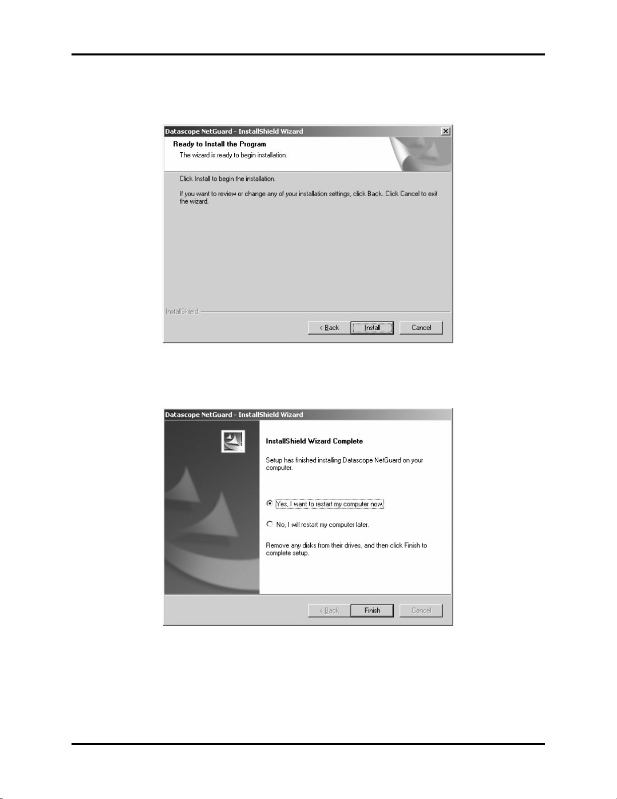
4. Enter the User Name, Password, and Server name (created during the server
installation), then select Next.
NOTE: For security purposes, the password entered will be
encrypted.
NOTE: The server name can be found in the Pre-Installation Form.
FIGURE 2-3 Configure Monitor
2 - 8 0070-10-0685 NetGuard Service Manual
Page 22
Repair Information Troubleshooting
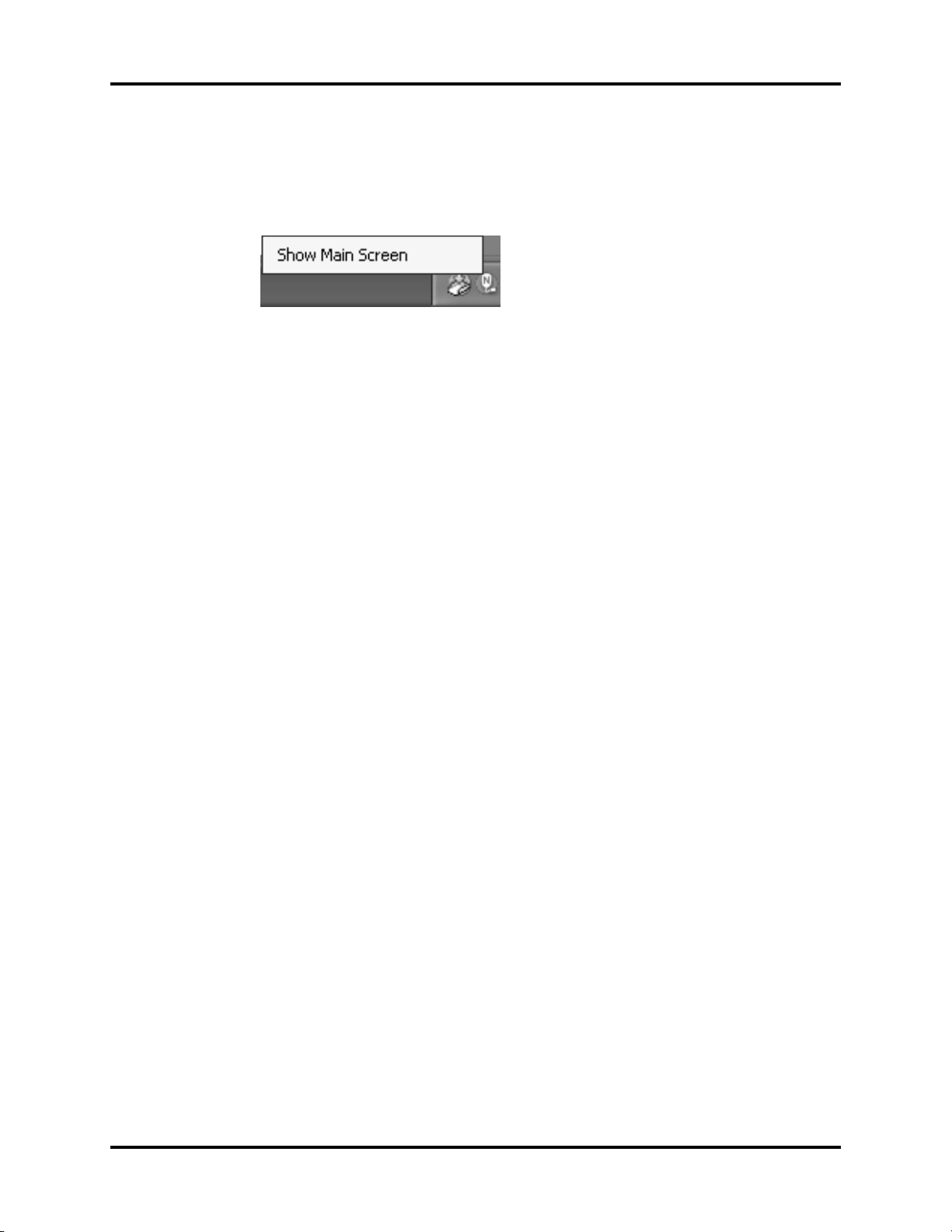
5. Optional - review all of the previous selections/input by selecting Back.
6. Select Install. The InstallShield Wizard Complete window opens.
FIGURE 2-4 Ready to Install the Program
7. Verify that the Yes, I want to restart my computer now. radio button is selected,
then select Finish. The PC reboots.
FIGURE 2-5 InstallShield Wizard
NetGuard Service Manual 0070-10-0685 2 - 9
Page 23
Troubleshooting Repair Information
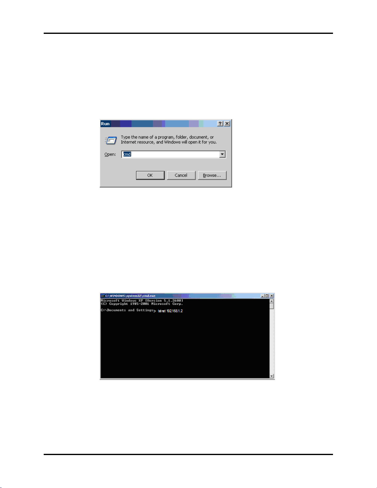
8. After a successful MS Windows login, notice the NetGuard icon in the Windows system
tray.
9. Double-click the NetGuard icon or right-click the NetGuard icon and select Show
Main Screen (shown in FIGURE 2-6). The NetGuard application is maximized.
FIGURE 2-6 NetGuard Icon
2.2.3 Programming the Access Points
The access point can be programmed while connected to the network switch or individually.
NOTE: If programming for the first time, be sure to have an IP
NOTE: For purposes of instruction, the IP address will indicate
NOTE: These instructions are written as an individual access point
address scheme designated for the A.P’s that will also match
the IP scheme for the server.
192.168.1.2.
is being programmed.
In the NetGuard Installation and Verification Document, fill in the following for the current
access point:
• IP address
• Communications MAC address
• Processor MAC address
• Location
• Software version
The PC used for programming will have the Telnet client that has the ability to transmit a text
file.
2 - 10 0070-10-0685 NetGuard Service Manual
Page 24
Repair Information Troubleshooting
2.2.4 Telnet Instruction
Telnet to the access point to verify the correct IP address, subnet mask, channel, and software
revision before you program.
1. Verify the access point is connected to the PoE Switch or PC you are programming from.
2. If connected to the PC, connect the PoE Injector to the access point.
3. Go to the Start button, select Run, and enter cmd.
FIGURE 2-7
4. Select OK.The Windows\system 32\.cmd.exe window (shown in FIGURE 2-8 )
appears.
5. After the “>” prompt, enter the word telnet followed by the IP address, then press
Enter.
NOTE: Be sure to have a space between “telnet” and the “IP
NOTE: Do not type the command telnet and select Enter. This will
address”. For example: telnet 192.168.1.2.
bring you to the telnet function which will not allow
programming. To exit the telnet function, type exit.
FIGURE 2-8
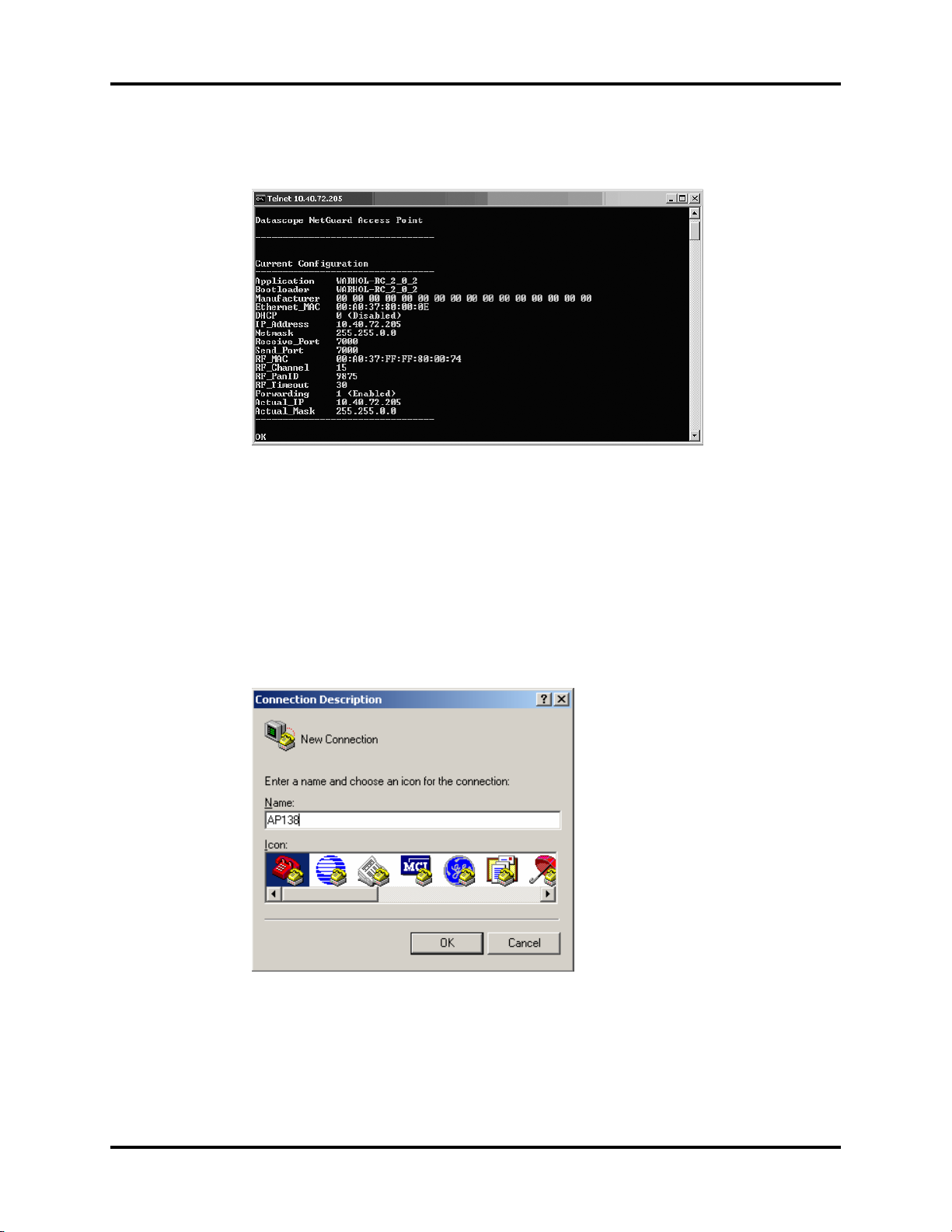
The Telnet window (shown in FIGURE 2-9) opens as Telnet 192.168.1.2 (or whichever IP
address was entered). The information listed is everything needed to know about the access
point.
NetGuard Service Manual 0070-10-0685 2 - 11
Page 25
Troubleshooting Repair Information
NOTE: See the list of changeable options further into these
FIGURE 2-9
instructions.
2.2.5 Program Instructions
After verifying the revision, the IP Address, and Subnet Mask of the access point, enter
HyperTerminal to program the access point.
1. Access HyperTerminal by selecting Start > Programs > Accessories >
Communications. Upon opening HyperTerminal, a Connection Description window
displays.
2. Enter a name (suggestion: one that corresponds with the access point new revision) and
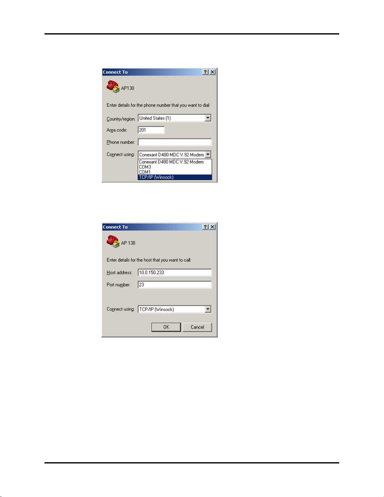
Icon, and select OK. A Connect To window displays (shown in FIGURE 2-10).
FIGURE 2-10
2 - 12 0070-10-0685 NetGuard Service Manual
Page 26
Repair Information Troubleshooting
3. Make the selection for TCP/IP.
FIGURE 2-11
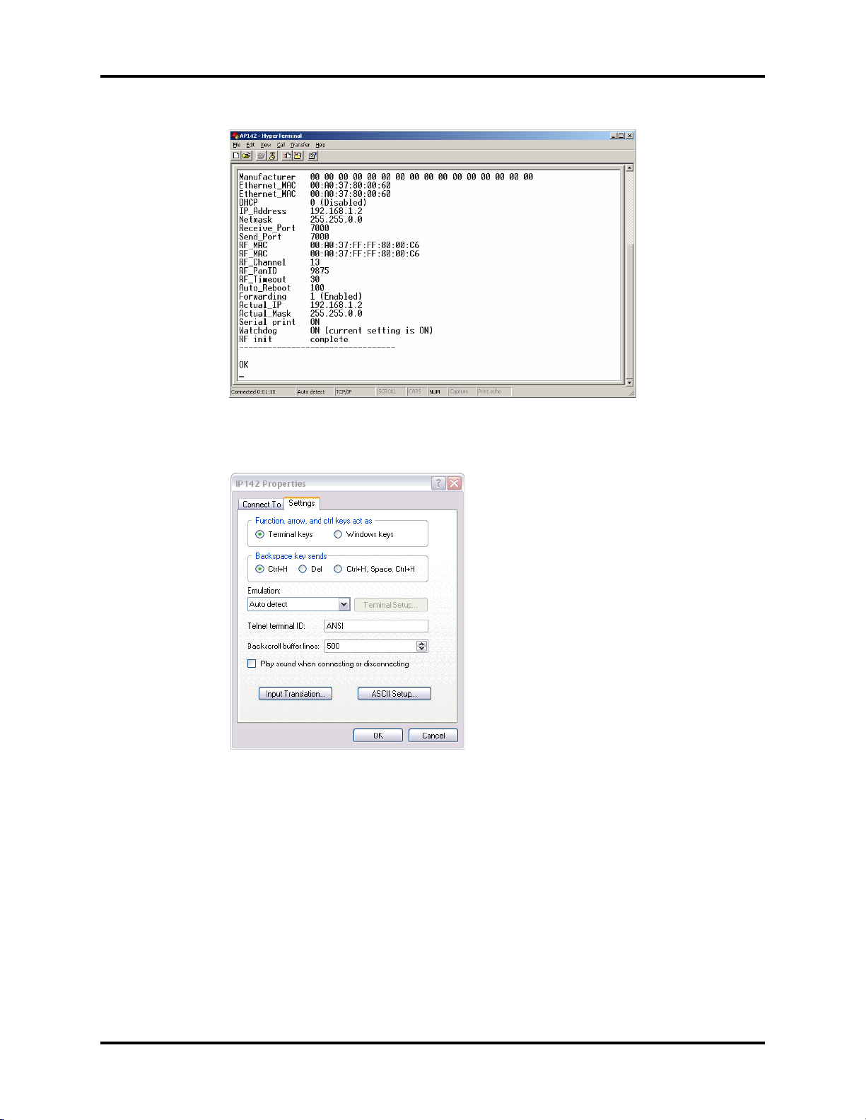
4. Enter the IP Address of the connected access point, then select OK. The “named”
HyperTerminal opens (shown in FIGURE 2-13).
FIGURE 2-12
NetGuard Service Manual 0070-10-0685 2 - 13
Page 27
Troubleshooting Repair Information
FIGURE 2-13
5. Select File > Properties, and the Settings tab to open the IP142 Properties window.
FIGURE 2-14
2 - 14 0070-10-0685 NetGuard Service Manual
Page 28
Repair Information Troubleshooting
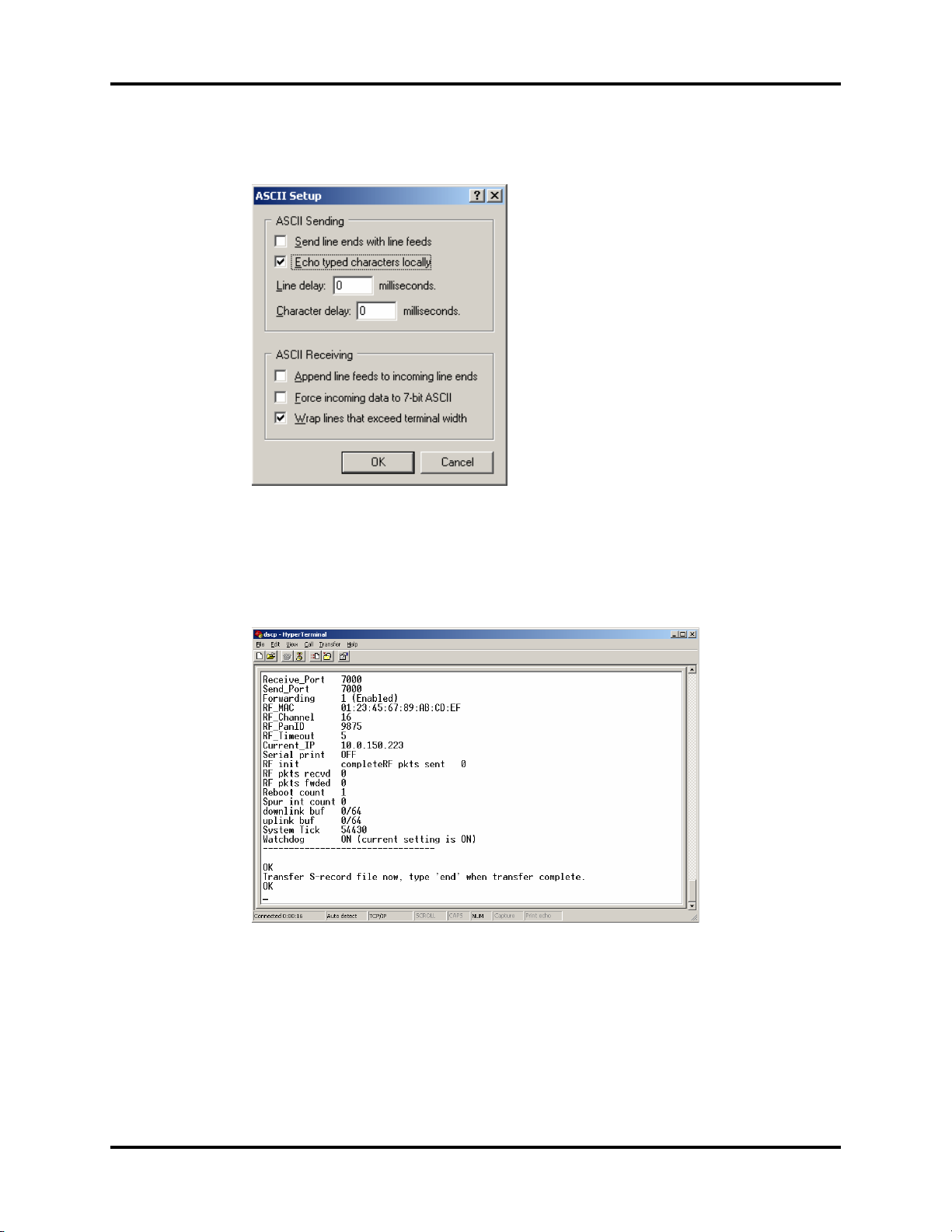
6. Select the ASCII Setup button and verify that the box for Echo typed characters
locally is checked. If not, check the box.
FIGURE 2-15
7. Select OK. In the IP142 Properties window, select OK.
8. At the OK prompt in the Hyperterminal window, enter the command upgrade. The
command Transfer S-record file now, type ‘end’ when transfer complete.
OK displays.
FIGURE 2-16
9. Transmit the file by selecting Transfer from the menu bar at the top of the window, then
select send text file. Find and select the access point program file.
NOTE: If the file is not a text file, go to Files of Type at the bottom
of the window and select “All files”.
NetGuard Service Manual 0070-10-0685 2 - 15
Page 29
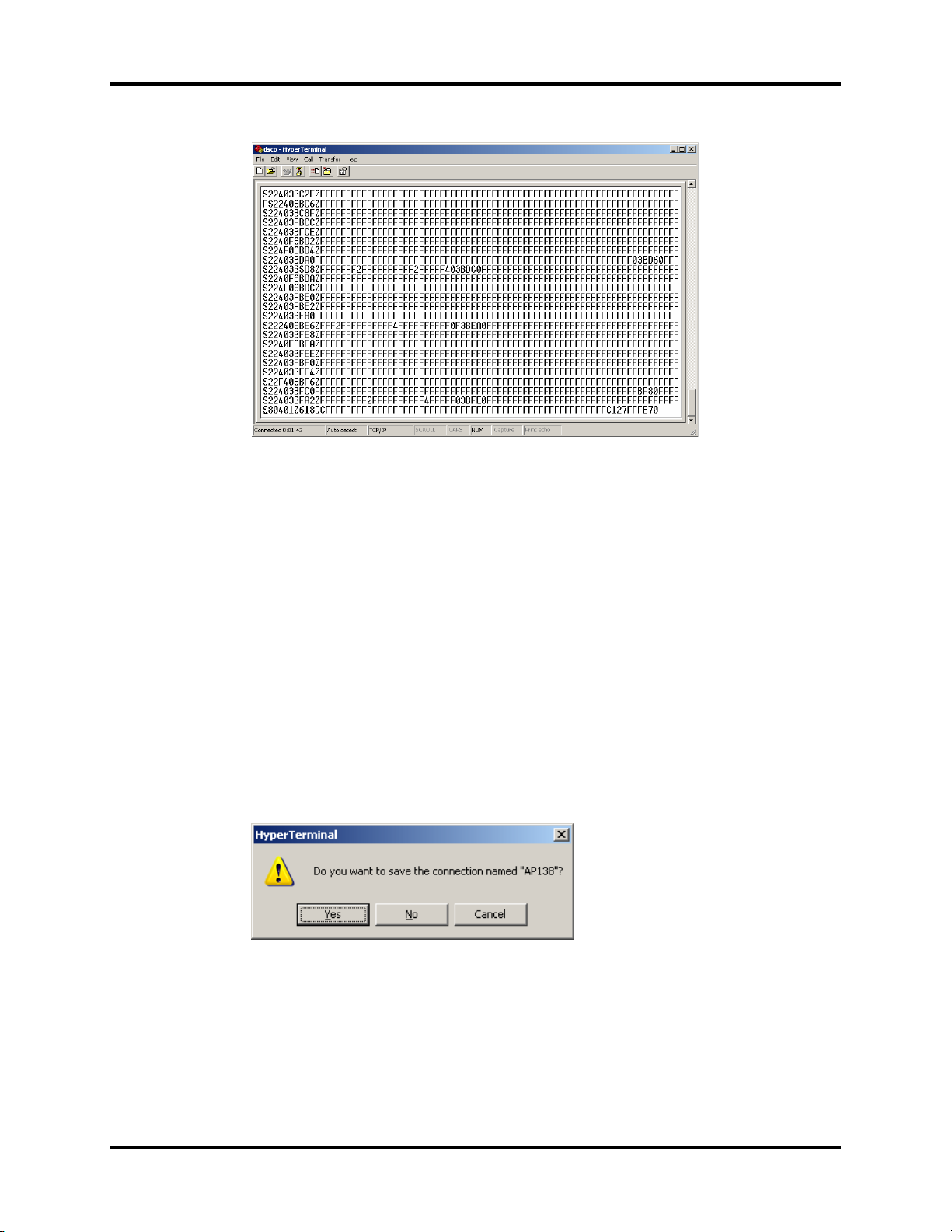
Troubleshooting Repair Information
FIGURE 2-17
NOTE: At the end of transmit, S8… starts the line. If not, refer to the
Troubleshooting section.
10. Once the entire file is transmitted, enter the command end.
NOTE: It will type over the S8… line.
The following messages appears as the image is upgraded:
Converting S-record file to binary image….complete
Flashing firmware image….complete
Reset access point to begin using saved configuration
OK
11. Enter reset or disconnect/reconnect the CAT5 cable.
12. Close the HyperTerminal window by selecting the “X” in the upper-right corner. At the
confirmation message, select Yes to save the connection and program more access
points.
FIGURE 2-18
13. Telnet to the access point by entering the static IP address. While in the Telnet window,
verify the configuration of the Ethernet_MAC and RF_MAC values to match the values
specified on the label on the back of the access point. If these are not configured, use
the following commands at the telnet prompt.
EthernetMediaAccessControl xx:xx:xx:xx:xx:xx
RadioMediaAccessControl xx:xx:xx:xx:xx:xx:xx.xx
2 - 16 0070-10-0685 NetGuard Service Manual
Page 30
Repair Information Troubleshooting
NOTE: Enter these commands exactly as shown using one space
between the text and MAC address numbers. The colons are
required.
14. Enter the command reset. This may take a few moments as the access point has to
reboot power. It is complete when the message Connection to host lost displays.
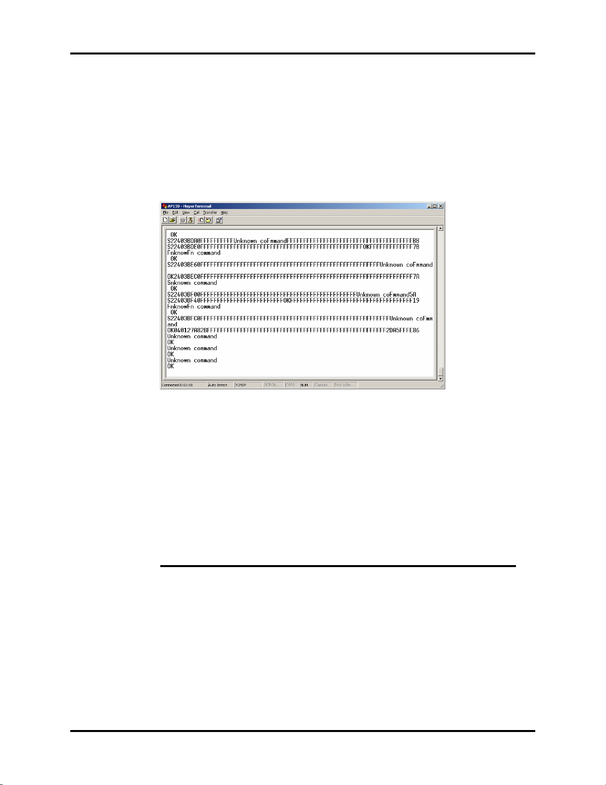
2.2.5.1 Troubleshooting
If the Unknown command OK displays, the access point did not program correctly.
FIGURE 2-19
Select the “disconnect” icon and start over. Check the following:
• PC has the correct IP address
• Type upgrade before Transmit
• Select the correct program file
2.2.5.2 Configurations
The configuration of the access point is accomplished via the maintenance interface. The
following parameters may be set:
COMMAND DESCRIPTION DEFAULT
AutoReset Period, in hours, at which the
DHCP Shall the access point use DHCP
IP_Address static IP address used when
Netmask static subnet mask used when
access point should perform an
automatic reboot.
to obtain its IP address (enabled)
or shall it use the configured
static IP address and subnet mask
(disabled)
DHCP is disabled.
DHCP is disabled
Default is 100 hours. A value of 0
means never booted.
Default is disabled.
Default is 192.168.1.2.
Default is 255.255.0.0
NetGuard Service Manual 0070-10-0685 2 - 17
Page 31

Troubleshooting Repair Information
COMMAND DESCRIPTION DEFAULT
Receive_Port UDP port upon which the access
point shall listen for packets.
Send_Port UDP to which the access point
shall direct all Ethernet traffic to.
RF_Channel 802.15.4 channel upon which
the access point will monitor for
devices transmitting packets.
Valid values are 11-25.
RF_PanID 802.15.4 PAN Identifier that the
access point shall use.
RF_Timeout Duration, in seconds, that an
associated device will remain on
the access points “Associated
Device List” without any RF
packets being received from the
device.
Forwarding Shall the access point perform
the packet forwarding function
(enabled) or not (disabled)
Default is 7000
Default is 7000
Default is 13.
Default is 9875.
Default is 30
Default is enabled.
2 - 18 0070-10-0685 NetGuard Service Manual
Page 32
3.0
Replacement Parts
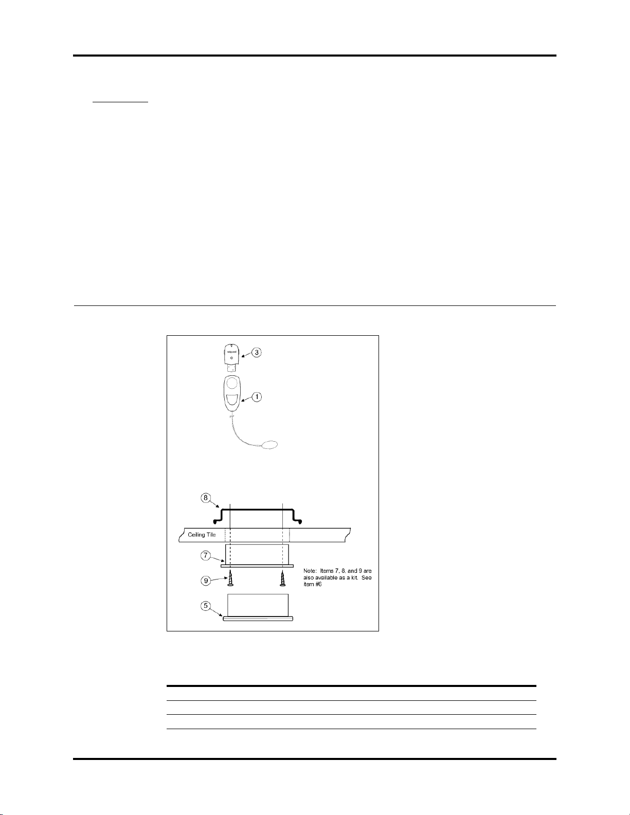
FIGURE 3-1 Replacement Part Diagram
ITEM NUMBER DESCRIPTION PART NUMBER
1 Electrode Disposable – Single 0998-00-1200-01
2 Electrode Disposable – 25 Pack 0998-00-1200-25
3 Reusable Device – Single 0998-00-1300-01
NetGuard Service Manual 0070-10-0685 3 - 1
Page 33

Replacement Parts
ITEM NUMBER DESCRIPTION PART NUMBER
4 Reusable Device – 10 Pack 0998-00-1300-10
5 Access Point - Single 0998-00-1400-01
6 Access Point Mounting Kit 0020-00-0163
7 Access Point Mounting Sleeve 0380-00-0538
8 Access Point Mounting Clamp 0386-00-0335
9 Screw, Mach, PanHd, #8-32 x .75” 0212-00-0812
10 Speakers, optional use at PC 0992-00-0107
11 Switch, 24-port, PoE Not shown
12 Server, 2.8GHz Dual Core processor or 2.0 GHz Quad
Core processor, 70GB HD
(Not shown)
Not shown
CAT5 Patch Cables
DESCRIPTION PART NUMBER
Cable, 6 ft. 0012-00-1274-01
Cable, 25 ft. 0012-00-1274-02
Cable, 50 ft. 0012-00-1274-03
Cable, 1 ft. 0012-00-1274-04
Cable, 2 ft. 0012-00-1274-05
Cable, 3 ft. 0012-00-1274-06
Cable, 10 ft. 0012-00-1274-07
3 - 2 0070-10-0685 NetGuard Service Manual
Page 34

4.0
System Requirements and
Specifications
4.1 Server - Minimum Requirements
4.1.1 Hardware
• Processor: 2.8 GHz Dual Core processor or 2.0 Quad Core processor
•Memory: 2 GB
• Hard Drive: 70 GB
• Network Interface Cards (NIC): Two available 1Gbps each
• CD/DVD: DVD writer
4.1.2 Software
• Operating System: MS Server 2003, R2 OS, SP2
• .NET Framework 2.0
• Internet Explorer 6.0
• Internet Information Services (IIS 6.0)
• SQL Server 2005, Express/Management Studio or Standard
• NetGuard Server software
NOTE: Windows updates must be set to manual or managed by
NetGuard Service Manual 0070-10-0685 4 - 1
hospital IT personnel.
Page 35

Switch - Minimum Requirements System Requirements and Specifications
4.2 Switch - Minimum Requirements
• Enough available 100 Mb ports for all NetGuard Access Points and the NetGuard
Server
• PoE (power over Ethernet) capable
• Must accept RJ 45 connectors
4.3 Client PC - Minimum Requirements
4.3.1 PC Hardware
• Processor: Pentium 4, 2 GHz processor or greater
• Memory: 768 MB RAM available for NetGuard, not including OS required RAM
• Capabilities:
• Play .wav audio files
• Display 1024 x 768 resolution video at 96 dpi
• Hard disk space available: 55 MB
4.3.2 PC Software
• Operating System: Windows XP Pro, SP2
• Internet Explorer 6.0
• .NET 2.0
• NetGuard Client software
NOTE: Windows updates must be set to manual or managed by
hospital IT personnel.
4.4 Mounting Rack (if applicable)
Wall mount or existing 19” rack.
4.5 Cabling
Refer to the Agency Compliance table on page 4-3.
4.6 Cable Connectors
RJ-45 CAT5 connectors are used at each end of the CAT5 cable to allow connections
between the access point and client PCs to the network switch and server.
4.7 Power Requirements
The server, PC, and switch are powered by the AC line cords supplied by the component
manufacturer. Upon purchase of the components, the user will specify the appropriate power
for their geographic location.
Mindray DS USA, Inc. requests that the AC power is connected to a UPS and to the facilities’
emergency power system.
4 - 2 0070-10-0685 NetGuard Service Manual
Page 36

System Requirements and Specifications Agency Compliance
4.8 Agency Compliance
Server: IEC60950, Information Technology Equipment - Safety - Part 1 General
Client PC: IEC60950, Information Technology Equipment - Safety - Part 1 General
Access Point: IEC60950, Information Technology Equipment - Safety - Part 1 General
Patient Device: IEC60950, Information Technology Equipment - Safety - Part 1 General
Cable: NEC/UL Classification: CMP (Reference: UL Standard 444 / CSA C22.2:
Cable connectors: Complies with ISO 9001:2000
Requirements
Requirements
Requirements
Requirements
Multi-National Harmonized Communication Cable Standards CSA c22.2 No.
214-94 and UL 444)
CEC/cUL Classification: CMP (Reference: UL Standard 444 / CSA C22.2:
Multi-National Harmonized Communication Cable Standards CSA C22.2 No
214-94 and UL 444).
CSA Flame Test Classification: FT6
IEC Specification: 11801 Category 5
ANSI/TIA/EIA Specification: 568-B.2 Category 5e (CAT 5e)
NetGuard Service Manual 0070-10-0685 4 - 3
Page 37

0070-10-0685 Revision C July 12, 2010
Page 38

Mindray DS USA, Inc. • 800 MacArthur Boulevard • Mahwah, NJ 07430 • USA •
Dom. Customer Service: 1.800.288.2121 • Intl. Customer Service: +1.201.995.8000 •
Dom. Fax: 1.800.926.4275 • Intl. Fax: +1.201.995.8680 • www.mindray.com
Mindray Medical Netherlands B.V.• P.O. Box 26 • 3870 CA Hoevelaken • The Netherlands •
Tel: +31 33 25 44 911 • Fax: +31 33 25 37 621
Mindray (UK) Limited • 3 Percy Road • St. John’s Park • Huntingdon • Cambridgeshire PE29 6SZ •
United Kingdom • Tel: 01480 416840 • Fax: 01480 436588
Mindray Medical France SARL • Europarc Créteil •123, Chemin des Bassins •
94035 Créteil Cedex • France • Tel: (0)1.45.13.91.50 • Fax: (0)1.45.13.91.51
Mindray Medical German GmbH • Zwischen den Bächen 4 • 64625 Bensheim • Germany •
Tel: +49.6251.17524-0 • Fax: +49.6251.17524-20
Mindray Medical International Ltd. • 2813 Office Tower, Convention Plaza • No 1 Harbour Road •
Wanchai • Hong Kong • Tel: +852 2793 5596 • Fax: +852 2344 8824
0002-08-8918
 Loading...