

Page 1
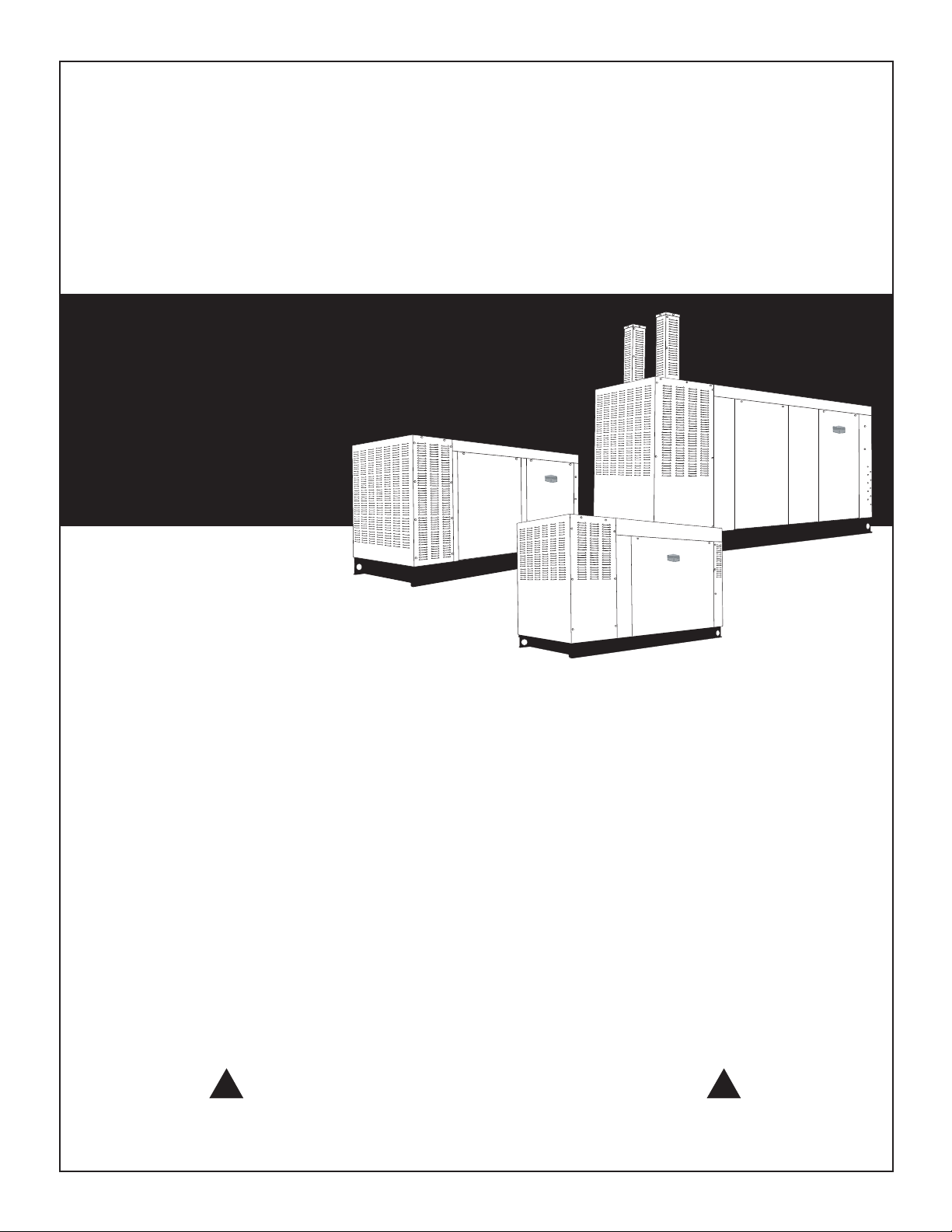
INSTALLATION
MANUAL
A new standard of reliability
Not intended for use in critical life support applications!
! !
OUTDOOR INSTALLATION ONLY!
This manual should remain with the unit.
Page 2
INTRODUCTION
Thank you for purchasing this model of the standby
generator set.
Every effort was expended to make sure that the
information and instructions in this manual are both
accurate and current at the time the manual was written. However, the manufacturer reserves the right to
change, alter or otherwise improve this product(s) at
any time without prior notice.
READ THIS MANUAL THOROUGHLY
If any portion of this manual is not understood, contact the nearest Dealer for starting, operating and
servicing procedures.
Throughout this publication, and on tags and decals
affixed to the generator, DANGER, WARNING,
CAUTION and NOTE blocks are used to alert personnel to special instructions about a particular service
or operation that may be hazardous if performed
incorrectly or carelessly. Observe them carefully.
Their definitions are as follows:
DANGER
After this heading, read instructions that, if not
strictly complied with, will result in serious personal injury, including death and/or property damage.
These safety warnings cannot eliminate the hazards
that they indicate. Common sense and strict compliance with the special instructions while performing
the service are essential to preventing accidents.
Four commonly used safety symbols accompany the
DANGER, WARNING and CAUTION blocks. The type
of information each indicates is as follows:
This symbol points out important safety infor-
mation that, if not followed, could endanger
personal safety and/or property of others.
This symbol points out potential explosion
hazard.
This symbol points out potential fire hazard.
This symbol points out potential electrical shock
hazard.
HOW TO OBTAIN SERVICE
When the generator requires servicing or repairs,
contact a Dealer for assistance. Service technicians
are factory-trained and are capable of handling all
service needs.
When contacting a Dealer about parts and service,
always supply the complete model number of the unit
as given on the front cover of the Owner’s Manual.
After this heading, read instructions that, if not
strictly complied with, may result in serious personal injury and/or property damage.
After this heading, read instructions that, if not
strictly complied with, could result in damage to
equipment and/or property.
NOTE:
After this heading, read explanatory statements
that require special emphasis.
Page 3

Table of Contents
Liquid-cooled Generators
INTRODUCTION ............................................... IFC
SAFETY RULES ....................................................2
Section 1 — GENERAL INFORMATION ............. 4
1.1 Generator Installation ...................................4
1.2 Before Installation .........................................4
1.3 Generator Location .......................................5
1.4 Generator Mounting and Support .................5
1.5 Unpacking .....................................................6
1.6 Lifting the Generator .....................................6
1.7 Fuel Systems .................................................6
1.8 Electrical Connections ...................................8
1.9 Battery Installation ......................................11
Section 2 — INSTALLATION ........................... 11
2.1 Transfer Switch ...........................................11
2.2 Unpacking ...................................................11
2.3 Mounting .....................................................12
Section 3 — OPERATION ................................ 12
3.1 Basic Standby Electric System ....................12
3.2 Standby Circuit Isolation Method ................12
3.3 Total Circuit Isolation Method .....................12
3.4 Connection Diagrams ..................................12
3.5 Wire Recommendations/Sizing ....................14
Section 4 — NOTES ........................................ 16
1
Page 4
IMPORTANT SAFETY INSTRUCTIONS
Liquid-cooled Generators
SAVE THESE INSTRUCTIONS – The manufacturer suggests that these rules for safe
operation be copied and posted in potential hazard areas. Safety should be stressed to all
operators, potential operators, and service and repair technicians for this equipment.
SAVE THESE INSTRUCTIONS – This manual contains important instructions that should be
followed during installation of the generator and batteries.
The engine exhaust from this product
contains chemicals known to the state
This product contains or emits chemicals
known to the state of California to cause
cancer, birth defects or other reproductive harm.
Study these SAFETY RULES carefully before installing,
operating or servicing this equipment. Become familiar
with this Owner’s Manual and with the unit. The generator can operate safely, efficiently and reliably only if
it is properly installed, operated and maintained. Many
accidents are caused by failing to follow simple and
fundamental rules or precautions.
The manufacturer cannot anticipate every possible
circumstance that might involve a hazard. The warnings in this manual, and on tags and decals affixed
to the unit are, therefore, not all inclusive. If using a
procedure, work method or operating technique that
the manufacturer does not specifically recommend,
ensure that it is safe for others. Also make sure the
procedure, work method or operating technique utilized does not render the generator unsafe.
WARNING:
of California to cause cancer, birth
defects or other reproductive harm.
WARNING:
DANGER
Despite the safe design of this generator,
operating this equipment imprudently, neglecting its maintenance or being careless can cause
possible injury or death. Permit only responsible
and capable persons to install, operate or maintain this equipment.
Potentially lethal voltages are generated by
these machines. Ensure all steps are taken to
render the machine safe before attempting to
work on the generator.
Parts of the generator are rotating and/or hot
during operation. Exercise care near running
generators.
2
GENERAL HAZARDS
• For safety reasons, the manufacturer recommends
that this equipment be installed, serviced and
repaired by an Dealer or other competent, qualified electrician or installation technician who is
familiar with applicable codes, standards and
regulations. The operator also must comply with
all such codes, standards and regulations.
• Installation, operation, servicing and repair of this
(and related) equipment must always comply with
applicable codes, standards, laws and regulations.
Adhere strictly to local, state and national electrical and building codes. Comply with regulations
the Occupational Safety and Health Administration
(OSHA) has established. Also, ensure that the
generator is installed, operated and serviced in
accordance with the manufacturer’s instructions
and recommendations. Following installation, do
nothing that might render the unit unsafe or in
noncompliance with the aforementioned codes,
standards, laws and regulations.
• The engine exhaust fumes contain carbon monoxide gas, which can be DEADLY. This dangerous
gas, if breathed in sufficient concentrations, can
cause unconsciousness or even death. For that
reason, adequate ventilation must be provided.
This should be considered prior to installing the
generator. The unit should be positioned to direct
exhaust gasses safely away from any building
where people, animals, etc., will not be harmed.
Any exhaust stacks that ship loose with the unit
must be installed properly per the manufacturer's
instruction, and in strict compliance with applicable codes and standards.
• Keep hands, feet, clothing, etc., away from drive
belts, fans, and other moving or hot parts. Never
remove any drive belt or fan guard while the unit
is operating.
• Adequate, unobstructed flow of cooling and ventilating air is critical to prevent buildup of explosive
gases and to ensure correct generator operation.
Do not alter the installation or permit even partial
blockage of ventilation provisions, as this can seriously affect safe operation of the generator.
• Keep the area around the generator clean and
uncluttered. Remove any materials that could
become hazardous.
• When working on this equipment, remain alert
at all times. Never work on the equipment when
physically or mentally fatigued.
• Inspect the generator regularly, and promptly
repair or replace all worn, damaged or defective
parts using only factory-approved parts.
Page 5

IMPORTANT SAFETY INSTRUCTIONS
Liquid-cooled Generators
• Before performing any maintenance on the generator, disconnect its battery cables to prevent
accidental start-up. Disconnect the cable from the
battery post indicated by a NEGATIVE, NEG or (–)
first. Reconnect that cable last.
• Never use the generator or any of its parts as a
step. Stepping on the unit can stress and break
parts, and may result in dangerous operating conditions from leaking exhaust gases, fuel leakage,
oil leakage, etc.
ELECTRICAL HAZARDS
• All generators covered by this manual produce
dangerous electrical voltages and can cause fatal
electrical shock. Utility power delivers extremely
high and dangerous voltages to the transfer switch
as well as the standby generator. Avoid contact
with bare wires, terminals, connections, etc., on
the generator as well as the transfer switch, if
applicable. Ensure all appropriate covers, guards
and barriers are in place before operating the generator. If work must be done around an operating
unit, stand on an insulated, dry surface to reduce
shock hazard.
• Do not handle any kind of electrical device while
standing in water, while barefoot, or while hands
or feet are wet. DANGEROUS ELECTRICAL
SHOCK MAY RESULT.
• If people must stand on metal or concrete while
installing, operating, servicing, adjusting or repairing this equipment, place insulative mats over a
dry wooden platform. Work on the equipment only
while standing on such insulative mats.
• The National Electrical Code (NEC), Article 250
requires the frame and external electrically conductive parts of the generator to be connected to
an approved earth ground and/or grounding rods.
This grounding will help prevent dangerous electrical shock that might be caused by a ground fault
condition in the generator set or by static electricity. Never disconnect the ground wire.
• Wire gauge sizes of electrical wiring, cables and
cord sets must be adequate to handle the maximum electrical current (ampacity) to which they
will be subjected.
• Before installing or servicing this (and related)
equipment, make sure that all power voltage
supplies are positively turned off at their source.
Failure to do so will result in hazardous and possibly fatal electrical shock.
• Connecting this unit to an electrical system normally supplied by an electric utility shall be by
means of a transfer switch so as to isolate the
generator electric system from the electric utility
distribution system when the generator is operating. Failure to isolate the two electric system power
sources from each other by such means will result
in damage to the generator and may also result
in injury or death to utility power workers due to
backfeed of electrical energy.
• Generators installed with an automatic transfer
switch will crank and start automatically when
normal (utility) source voltage is removed or is
below an acceptable preset level. To prevent such
automatic start-up and possible injury to personnel, disable the generator’s automatic start circuit
(battery cables, etc.) before working on or around
the unit. Then, place a “Do Not Operate” tag on
the generator control panel and on the transfer
switch.
• In case of accident caused by electric shock, immediately shut down the source of electrical power. If
this is not possible, attempt to free the victim from
the live conductor. AVOID DIRECT CONTACT
WITH THE VICTIM. Use a nonconducting implement, such as a dry rope or board, to free the victim from the live conductor. If the victim is unconscious, apply first aid and get immediate medical
help.
• Never wear jewelry when working on this equipment. Jewelry can conduct electricity resulting in
electric shock, or may get caught in moving components causing injury.
FIRE HAZARDS
• Keep a fire extinguisher near the generator at all
times. Do NOT use any carbon tetra-chloride type
extinguisher. Its fumes are toxic, and the liquid
can deteriorate wiring insulation. Keep the extinguisher properly charged and be familiar with its
use. If there are any questions pertaining to fire
extinguishers, consult the local fire department.
EXPLOSION HAZARDS
• Do not smoke around the generator. Wipe up any
fuel or oil spills immediately. Ensure that no combustible materials are left in the generator compartment, or on or near the generator, as FIRE or
EXPLOSION may result. Keep the area surrounding the generator clean and free from debris.
• This generator may operate using one of several types of fuels. All fuel types are potentially
FLAMMABLE and/or EXPLOSIVE and should be
handled with care. Comply with all laws regulating the storage and handling of fuels. Inspect the
unit’s fuel system frequently and correct any leaks
immediately. Fuel supply lines must be properly installed, purged and leak tested according to
applicable fuel-gas codes before placing this equipment into service.
• Gaseous fluids such as natural gas and liquid propane (LP) gas are extremely EXPLOSIVE. Natural
gas is lighter than air, and LP gas is heavier than
air; install leak detectors accordingly.
3
Page 6
Section 1 - General Information
Liquid-cooled Generators
1.1 GENERATOR INSTALLATION
This equipment is a liquid-cooled, engine-driven
generator set. The generator is designed to supply
electrical power that operates critical electrical loads
during utility power failure. The unit has been factory-installed in a weather resistant, all metal enclosure
and is intended for outdoor installation only.
If this generator is used to power electrical load
circuits normally powered by a utility power
source, it is required by code to install a transfer switch. The transfer switch must effectively
isolate the electric system from the utility distribution system when the generator is operating
(NEC 701). Failure to isolate an electrical system
by such means results in damage to the generator and may also result in injury or even death
to utility power workers due to backfeed of
electrical energy.
1.2 BEFORE INSTALLATION
Before installing this equipment, check the ratings
of both the generator and the transfer switch. Read
“Emergency Isolation Method” and “Total Circuit
Isolation Method”.
The generator’s rated wattage/amperage capacity
must be adequate to handle all electrical loads that
the unit will power. The critical (essential) loads may
need to be grouped together and wired into a separate “emergency” distribution panel.
DANGER
Connecting this generator to an electrical system
normally supplied by an electric utility shall be
by means of a transfer switch, so as to isolate
the electric system from the utility distribution
system when the generator is operating. Failure
to isolate the electric system by these means
will result in damage to the generator and may
also result in injury or death to utility workers
due to backfeed of electrical energy.
If an open bottom is used, the engine-generator
is to be installed over non-combustible materials and should be located such that combustible
materials are not capable of accumulating under
the generator set.
Only qualified, competent installation contractors
or electricians thoroughly familiar with applicable
codes, standards and regulations should install this
standby electric power system. The installation must
comply strictly with all codes, standards and regulations pertaining to the installation.
After the system has been installed, do nothing
that might render the installation in noncompliance with such codes, standards and regulations.
1.2.1 NFPA STANDARDS
The following published standards booklets pertaining to standby electric systems are available form
the National Fire Protection Association (NFPA),
Batterymarch Park, Quincy, MA 02269:
• NFPA No. 37, STATIONARY COMBUSTION
ENGINES AND GAS TURBINES
• NFPA No. 54, NATIONAL FUEL GAS CODE
• NFPA No. 58, LIQEEFIED PETROLEUM GAS
CODE
• NFPA 70, NATIONAL ELECTRIC CODE (NEC)
• NFPA 99, STANDARD FOR HEALTH CARE
FACILITIES
• NFPA 101, LIFE SAFETY CODE
• NFPA 110, STANDARD FOR EMERGENCY AND
STANDBY POWER SYSTEMS
• NFPA 220, STANDARD TYPES OF BUILDING
CONSTRUCTIN
NOTE:
It is essential to use the latest version of any standard to ensure that the generator and its accessories comply with all the applicable standards and
local codes.
1.2.2 OTHER PUBLISHED STANDARDS
In addition to NFPA standards, the following information pertaining to the installation and use of standby
electric systems is available:
• Article X, NATIONAL BUILDING CODE, available
from the American Insurance Association, 85 John
Street, New York, N.Y. 10038.
• AGRICULTURAL WIRING HANDBOOK, obtainable
from the Food and Energy Council, 909 University
Avenue, Columbia, MO, 65201.
• ASAE EP-364.2, INSTALLATION AND
MAINTENANCE OF FARM STANDBY ELECTRIC
POWER, available from the American Society
of Agricultural Engineers, 2950 Niles Road, St.
Joseph, MI 49085.
• A52.1, AMERICAN NATIONAL STANDARD
FOR CHIMNEYS, FIREPLACES AND VENTING
SYSTEMS, available from the American National
Standard Institute, 1430 Broadway, New York, N.Y.
10018.
4
Page 7

Section 1 - General Information
Liquid-cooled Generators
NOTE:
It is essential to use the latest version of any standard to ensure that the generator and its accessories comply with all the applicable standards and
local codes.
The installer must comply with all applicable state
and local codes.
1.3 GENERATOR LOCATION
Install the generator set, in its protective enclosure
outdoors, where adequate cooling and ventilating air
always is available. Consider these factors:
• Install the unit where air inlet and outlet openings will not become obstructed by leaves, grass,
snow, etc. If prevailing winds will cause blowing or
drifting, consider using a windbreak to protect the
unit.
• Install the generator on high ground where water
levels will not rise and endanger it.
• This genset must be installed on a level surface.
The base frame must be level within 1/2 inch all
around.
• Allow sufficient room on all sides of the generator
for maintenance and servicing. This unit must be
installed in accordance with current applicable
NFPA 37 and NFPA 70 standards, as well as any
other federal, state and local codes for minimum
distances from other structures.
• Where strong prevailing winds blow from one
direction, face the generator air inlet openings into
the prevailing winds.
• Install the generator as close as possible to the
transfer switch. This reduces the length of wiring
and conduit.
• Install the generator as close as possible to
the fuel supply, to reduce the length of piping.
HOWEVER, REMEMBER THAT LAWS OR CODES
MAY REGULATE THE DISTANCE.
1.4 GENERATOR MOUNTING AND
SUPPORT
A CONCRETE BASE:
When designing a concrete base slab, all federal, state
and local codes should be followed. Special attention should be given to the concrete base slab which
should exceed the length and width of the generator
by a minimum of six (6) inches (0.152 meters) on all
sides.
Retain the generator compartment to the concrete
slab with masonry bolts.
1.4.1 COMBUSTIBLE FLOOR AND ROOF
PROTECTION
If the generator must be installed on any combustible
floor or roof, comply with the following rules:
• Place a layer of non-combustible insulation, followed by a layer of sheet metal beneath the unit’s
mounting base rails (Figure 1.1).
• Both the layer of insulation and the sheet metal
must extend beyond the generator base to a distance of at least 12 inches (30.5 cm) on all sides.
Figure 1.1 — Combustible Floor and Roof
Protection
For rooftop or building structure mounting, it is recommended that spring isolators be installed between
the engine frame and the mounting system. A minimum of six (6) isolators are required and must be
located at the front and rear cross members and the
center of the frame.
Since the entire bottom of the genset is now exposed,
it should be covered with a metal plate to keep out
small animals and protect the integrity of the internal
parts of the genset. Genset movement is more intense
with spring isolation, so flexible connections for the
fuel and the electrcal conduits are also required.
NOTE:
Consult the local building codes which may vary.
5
Page 8

1.5 UNPACKING
Section 1 — General Information
Liquid-cooled Generators
1.7.2 PROPERTIES OF GASEOUS FUELS
1.5.1 UNPACKING PRECAUTIONS
Handle shipping cartons and crates with care. Use
care to avoid damage from dropping, bumping, collision, etc. Store and unpack cartons with the proper
side up, as noted on the shipping carton.
1.5.2 INSPECTION
After unpacking, carefully inspect the generator for
any damage that may have occurred during shipment. If loss or damage is noted at the time of delivery, have the person(s) making delivery note all damage on the freight bill or affix their signature under
the consignor’s memo of loss or damage.
1.6 LIFTING THE GENERATOR
When lifting or hoisting equipment is used, be
careful not to touch overhead power lines. The
generators weight of more than 900 pounds
requires proper tools, equipment, and qualified
personnel to be used in all phases of handling
and unpacking.
1.7 FUEL SYSTEMS
1.7.1 INTRODUCTION TO GASEOUS FUEL
SYSTEMS
DANGER
Gaseous fuels, such as LP and natural gas, are
highly volatile and their vapors are explosive.
LP gas is heavier than air and will settle in low
areas. Natural gas is lighter than air and will
settle in high areas. Even the slightest spark
can ignite these fuels and cause an explosion.
For safety, all codes, standards and regulations
pertaining to the installation and use of gaseous
fuels must be strictly complied with.
Local fuel gas codes may vary widely. For that reason,
it is recommended that a local gas distributor or
installer be consulted when installing a gaseous fuel
supply system.
In the absence of local fuel gas codes and regulations,
booklets published by the National Fire Protection
Association (NFPA) may be used as sources of information.
Natural Gas
Natural gas is lighter than air. It is found in the
gaseous state at normal ambient temperatures and
pressures. It is highly explosive and can be ignited at
the slightest spark. For that reason, fuel lines must
be free of leaks and adequate ventilation is absolutely
essential.
Local fuel/gas codes usually dictate the maximum
pressure at which natural gas can enter a structure.
In order to reduce the gas pressure to that required
by law, a PRIMARY REGULATOR is required.
LP Gas
Liquefied petroleum (LP) gas is heavier than air. The
gas vapors are explosive and, like natural gas, can be
ignited by the slightest spark.
LP tank pressure is dependent on the ambient temperature and can be as high as 200 psi. A primary
regulator is required at the tank to reduce the pressure to the required five to 14 inches of water column
for units less than 70kW, or 11 to 14 inches of water
column for units 70kW and larger.
1.7.3 THE NATURAL GAS SYSTEM
A typical natural gas system is shown in Figure 1.2,
below. The maximum pressure at which the gas can
enter a building is established by code and may vary
from area to area. A primary regulator is required to
reduce gas supply pressures to the required safe level
before the gas enters a structure.
The primary regulator may or may not be provided
by the gas supplier. The gas distribution company
will usually provide piping from the main distribution line to the generator site. It is the responsibility
of the gas supplier to ensure that sufficient gas pressure is available to operate the primary regulator.
From the primary regulator, gas flows to the generator connection. A flexible length of gas line is required
between rigid piping and the gas connection at the
generator. The generator fuel system consists of an
electrical fuel shutoff valve/regulator assembly and a
gas actuator.
The secondary regulator reduces gas pressure to
about five inches of water column before the gas Is
delivered to the actuator.
NOTE:
Gas pressure from the primary regulator (supplied
by the installing contractor) to the generator's fuel
shutoff valve should not exceed 14 inches of water
column. Units can operate with the pressure as
low as five inches of water column.
6
Page 9

Section 1 — General Information
Liquid-cooled Generators
Figure 1.2 — Typical Natural Gas System
Primary Regulator
(Supplied by
Installing
Contractor)
Manual Shutoff
Valve
Generator Base
Flex Fuel Line
(Supplied
with Unit)
Follow the local codes on selecting the required AGA
approved, and UL listed, for NG application flexible
portion of the fuel line (supplied by the installing
contractor).
1.7.4 LP GAS VAPOR WITHDRAWAL SYSTEM
This type of system utilizes the vapors formed above
the liquid fuel in the supply tank (see Figure 1.3).
Approximately 10 to 20 percent of the tank capacity
is needed for fuel expansion from the liquid to the
vapor state. Gas pressure requirements for an LP
vapor system at the frame of the generator are the
Gas Actuator
Fuel Shutoff/Regulator
Assembly
11 - 14" Water
Column (>= 70 kW)
5 - 14" Water
Column (< 70 kW)
same as those listed for natural gas in "The Natural
Gas System". See Table 1 for information regarding
the vapor capacity of LP tanks. The installer should
be aware of the following:
• When ambient temperatures are low and engine
fuel consumption is high, the vapor withdrawal
system may not function efficiently.
• Ambient temperatures around the supply tank
must be high enough to sustain adequate vaporization or the system will not deliver the needed fuel
volume.
Manual Shutoff Valves
Primary Regulator
(Supplied by
Fuel
Tank
Installing
Contractor)
Figure 1.3 — Typical LP Gas Vapor Withdrawal System
Generator Base
Flex Fuel Line
(Supplied
with Unit)
7
Gas Actuator
Fuel Shutoff/Regulator
Assembly
11 - 14" Water
Column (>= 70 kW)
5 - 14" Water
Column (< 70 kW)
Page 10

GROU
G
UG
Section 1 - General Information
Liquid-cooled Generators
• In addition to the cooling effects of ambient air, the
vaporization process itself provides an additional
cooling effect.
1.7.5 GASEOUS FUEL SYSTEM PIPING
NOTE:
The information below is to assist in planning
gaseous fuel installation. In NO WAY should this
information be interpreted to conflict with applicable fuel gas codes. Contact the local jurisdiction
if questions arise.
The following general rules apply to piping used in
gaseous fuel systems:
• The piping should be of black iron, rigidly mounted and protected against vibration.
• Install the supplied length of flexible hose between
the generator connection point and rigid piping.
The supplied flexible hose is not to be installed
underground or in contact with ground. The
flexible hose is for in-line installation only.
Bends, kinks or off-center in-line installation of
flexible hose is NOT allowed.
• Piping must be of the correct size to maintain the
required supply pressures and volume flow under
varying conditions (see Table 2).
• Installed piping must be properly purged and leaktested, in accordance with applicable codes and
standards.
• Use an approved pipe sealant or joint compound
on all threaded fittings, to reduce the possibility of
leakage.
NOTE:
In the absence of local purging and leak test standards, NFPA No. 54 may be used as a guide.
Proper grounding helps protect personnel against
electrical shock in the event of a ground fault condition in the generator or in connected electrical devices. In addition, grounding helps dissipate static electricity that often builds up in ungrounded devices.
Figure 1.4 – Generator Grounding Lug (typical)
NDIN
L
1.8.2 BATTERY CHARGER CONNECTION
The generator has been equipped with a 2 Amp battery charger installed in the control panel. Power
leads for the charger have been run to the connection box (Figure 1.5). On units equipped with 2.5L
engines, this connection is found in the control panel.
The terminals will need to be supplied from a
120VAC, 15 Amp circuit.
Figure 1.5 — Battery Charger Connection
1.8 ELECTRICAL CONNECTIONS
1.8.1 GROUNDING THE GENERATOR
A GROUNDING LUG is provided on the generator
mounting base for the purpose of grounding the
frame and the external electrically conductive parts
of this equipment to an approved earth ground and/
or grounding rods where required by the National
Electrical Code (Figure 1.4). Consult a qualified
electrician for grounding requirements in the area.
Groudning procedures must meet local regulations.
DANGER
Do not connect the ground wire to any pipe
that carries a flammable or explosive substance
– FIRE or an EXPLOSION may result.
8
Factory
Customer
to provide
120 VAC
15 Amp
(See the wiring diagram in the Owner's Manual that
is supplied with the unit.)
connection
charger in
{}
provided
to battery
control
panel.
Page 11

Section 1 — General Information
Liquid-cooled Generators
TABLE 1 — VAPOR CAPACITY OF PROPANE STORAGE TANKS
To Use: Go to the First column and pick the required kW load and then pick the minimum ambient temperature
(40º, 20º or 0º F) that the generator would be operating in. The third column (tank capacity) will give the required
tank size to continually produce the given fuel flow.
Operating
Max kW Minimum Hours @ Tank Capacity Length Dia Overall
Vapor Temp Max kW (Gallons) Inches Inches Ht. Inches
30 40 24
20 20 35 120 57 24 33
10 0 67
35 40 26
25 20 36 150 68 24 33
12 0 72
60 40 26
40 20 38 250 94 30 39
20 0 74
80 40 26
50 20 40 325 119 30 39
25 0 77
100 40 31
60 20 51 500 119 37 46
30 0 100
150 40 35
100 20 53 850 165 41 50
50 0 105
170 40 36
120 20 51 1000 192 41 50
60 0 103
Propane storage tanks can provide either a liquid or a vapor supply to the generator. The above chart is for vapor
withdrawal only and provides the kW output or amount of vapor that can be withdrawn at a given temperature
while keeping the temperature of the liquid above the boiling point. If the withdrawal rate is too high, the LP temperature goes below the boiling point, the pressure drops to zero and no vapor can be withdrawn. A primary regulator is also required at the tank to reduce the line pressure to the generator to 5-14 inches of water column.
Propane Conversions: 36.38 ft
3
= 90,500 btu = 1 gal • 1lb = 21,500 btu = 8.56 ft
3
Figure 1.6 — Propane Storage Tank
9
Page 12

Section 1 - General Information
Liquid-cooled Generators
TABLE 2 — GAS FLOW-PIPE SIZE CHART
This table is based on a specific gravity of 1.00 (specific gravity of air). For that reason, a correction is required
when the fuel used has a different specific gravity. The fuel’s specific gravity can be obtained from the fuel supplier.
The table is also based on a pressure drop of 0.3, which allows for a nominal amount of restrictions from bends,
fittings, etc. An example of how to calculate pipe size follows the table.
Example: It is determined that a generator set running at 100% of rated load on natural gas requires 545 cubic
feet of gas per hour. The unit is located 75 feet from the supply tank and will use gas having a specific gravity of
0.65 (multiplier is 0.962). From the table below, it is apparent that a 1-1/2 inch pipe will deliver 524.29 cubic feet
of gas per hour. The next larger pipe (2 inch) will deliver 1120 cubic feet per hour and, when the correction factor
is applied, will actually deliver 1077.4 cubic feet per hour. The 2 inch pipe is required at the given distance of 75
feet. Pressure drop does not have to be considered unless an unusual number of fittings, bends or other restrictions are used. In such unusual cases, the fuel supplier will usually specify which multiplier is applicable.
Length of Pipe Iron Pipe Size (IPS Inches)
(In Feet) 1/2” 3/4” 1” 1-1/4” 1-1/2” 2” 2-1/2” 3” 4” 6” 8”
15 76 172 345 750 1220 2480 3850 6500 13880 38700 79000
30 52 120 241 535 850 1780 2750 4700 9700 27370 55850
45 43 99 199 435 700 1475 2300 3900 7900 23350 45600
60 38 86 173 380 610 1290 2000 3450 6800 19330 39500
75 77 155 345 545 1120 1750 3000 6000 17310 35300
90 70 141 310 490 1000 1560 2700 5500 15800 32250
105 65 131 285 450 920 1430 2450 5100 14620 29850
120 120 270 420 860 1340 2300 4800 13680 27920
150 109 242 380 780 1220 2090 4350 12240 25000
180 100 225 350 720 1120 1950 4000 11160 22800
210 92 205 320 660 1030 1780 3700 10330 21100
240 190 300 620 970 1680 3490 9600 19740
270 178 285 580 910 1580 3250 9000 18610
300 170 270 545 860 1490 3000 8500 17660
450 140 226 450 710 1230 2500 7000 14420
600 119 192 390 600 1030 2130 6000 12480
CORRECTION FACTORS
Specific Specific Pressure
Gravity Multiplier Gravity Multiplier Drop Multiplier
0.50 1.10 1.0 0.775 0.1 0.577
0.55 1.04 1.2 0.707 0.2 0.815
(Sewage Gas)
0.60 1.00 1.4 0.655 0.3 1.000
0.65 0.962 1.5 0.633 0.5 1.29
(Natural Gas) (Propane)
0.70 0.926 1.7 0.594 1.0 1.83
0.80 0.867 1.9 0.565 2.0 2.58
0.90 0.817 2.1 0.535 5.0 4.08
10
(Butane)
Page 13

Section 2 — Installation
Liquid-cooled Generators
1.9 BATTERY INSTALLATION
DANGER
Standby generators installed with automatic
transfer switches will crank and start automatically when NORMAL (UTILITY) source voltage is
removed or is below an acceptable preset level.
To prevent such automatic start-up and possible injury to personnel, do not connect battery
cables until certain that normal source voltage at
the transfer switch is correct and the system is
ready to be placed into operation.
Storage batteries give off explosive hydrogen
gas. This gas can form an explosive mixture
around the battery for several hours after charging. The slightest spark can ignite the gas and
cause an explosion. Such an explosion can shatter the battery and cause blindness or other
injury. Any area that houses a storage battery
must be properly ventilated. Do not allow smoking, open flame, sparks or any spark producing
tools or equipment near the battery.
Battery electrolyte fluid is an extremely caus-
tic sulfuric acid solution that can cause severe
burns. Do not permit fluid to contact eyes, skin,
clothing, painted surfaces, etc. Wear protective
goggles, protective clothing and gloves when
handling a battery. If fluid is spilled, flush the
affected area immediately with clear water.
Do not dispose of the battery in a fire. The bat-
tery is capable of exploding.
Do not open or mutilate the battery. Released
electrolyte can be toxic and harmful to the skin
and eyes.
The battery represents a risk of high short circuit
current. When working on the battery, always
remove watches, rings or other metal objects,
and only use tools that have insulated handles.
• Spilled electrolyte is to be washed down with an
acid-neutralizing agent. A common practice is to
use a solution of one pound (500 grams) bicarbonate of soda to one gallon (4 liters) of water. The
bicarbonate of soda solution is to be added until
the evidence of reaction (foaming) has ceased. The
resulting liquid is to be flushed with water and the
area dried.
Lead acid batteries present a risk of fire because
they generate hydrogen gas. The following procedure are to be followed:
• DO NOT SMOKE when near batteries,
• DO NOT cause flame or spark in battery area, and
• Discharge static electricity from body before touching batteries by first touching a grounded metal
surface.
Servicing of batteries is to be performed or supervised by personnel knowledgeable of batteries and
the required precautions. Keep unauthorized personnel away from batteries.
For recommended batteries, see the “Specifications”
section in the Owner’s Manual. All batteries must
be at 100 percent state-of-charge before they are
installed on the generator.
When using maintenance-free batteries, it is not necessary to check the specific gravity or electrolyte level.
Have these procedures performed at the intervals
specified in the “Maintenance” section in the Owner’s
Manual. A negative ground system is used. Battery
connections are shown on the wiring diagrams. Make
sure all batteries are correctly connected and terminals are tight. Observe battery polarity when connecting batteries to the generator set.
NOTE:
Damage will result if the battery connections are
made in reverse.
1.9.1 VENTED BATTERIES
The electrolyte is a dilute sulfuric acid that is
harmful to the skin and eyes. It is electrically
conductive and corrosive. The following procedures are to be observed:
• Wear full eye protection and protective clothing,
• Where electrolyte contacts the skin, wash it off
immediately with water,
• Where electrolyte contacts the eyes, flush thoroughly and immediately with water and seek
medical attention, and
2.2 UNPACKING
Carefully unpack the transfer switch. Inspect closely
for any damage that might have occurred during
shipment. The purchaser must file with the carrier
any claims for loss or damage incurred while in transit.
Check that all packing material is completely removed
from the switch prior to installation.
Attach any lifting device to the transfer switch
mounting holes or brackets only. DO NOT LIFT THE
SWITCH AT ANY OTHER POINT.
11
Page 14

Section 3 - Operation
Liquid-cooled Generators
2.3 MOUNTING
Mounting dimensions for the transfer switch enclosure can be found in the transfer switch owner’s
manual. Enclosures are typically wall-mounted.
Handle transfer switches carefully when install-
ing. Do not drop the switch. Protect the switch
against impact at all times, and against construction grit and metal chips. Never install a transfer
switch that has been damaged.
Install the transfer switch as close as possible to the
electrical loads that are to be connected to it. Mount
the switch vertically to a rigid supporting structure.
To prevent switch distortion, level all mounting
points. If necessary, use washers behind mounting
holes to level the unit. Never install the switch where
water or any corrosive substance might drip into the
enclosure.
3.1 BASIC STANDBY ELECTRIC
SYSTEM
Figure 3.1 shows a schematic diagram of a basic
standby electric system. Both the UTILITY power
supply and the STANDBY (GENERATOR) output are
connected to an approved transfer switch. The transfer switch is required by electrical code and serves
the following functions:
• Allows the LOAD circuits to be connected to only
one power supply at a time.
• Prevents electrical backfeed between the generator
and the UTILITY power circuits.
Figure 3.1 – Basic Standby Electric System
3.2 STANDBY CIRCUIT ISOLATION
METHOD
This prevents overloading the generator by keeping
electrical loads below the wattage/amperage capacity of the generator. If the generator is powering only
designated loads, within the wattage/amperage capacity, during utility power outages, consider using the
emergency circuit isolation method.
Designated electrical loads are grouped together and
wired into a separate “Standby Distribution Panel.”
Load circuits powered by that panel are within the
wattage/amperage capacity of the generator set. When
this method is used, it is difficult to overload the generator. The transfer switch must meet the following
requirements:
• It must have an ampere rating equal to the total
amperage rating of the standby distribution panel
circuit.
• Have it installed between the building’s main distri-
bution panel and the standby distribution panel.
3.3 TOTAL CIRCUIT ISOLATION
METHOD
When a generator capable of powering all electrical
loads in the circuit is to be installed, use the “Total
Circuit Isolation Method.” It is possible for the generator to be overloaded when this isolation method is
employed. The following apply to the transfer switch
in this type of system.
• Ampere rating of the transfer switch must equal
the ampere rating of the normal incoming utility
service.
• The transfer switch is installed between the util-
ity service entrance and the building distribution
panel.
Notice that both the STANDBY and the UTILITY
power supplies to the transfer switch are protected
against overload by a main line circuit breaker.
12
3.4. CONNECTION DIAGRAMS
All wiring in the standby electric power system must
be in strict compliance with applicable codes, standards and regulations. Such wiring must be properly
supported, routed, and connected. In addition, wiring must be properly sized to carry the maximum
load current to which is will be subjected.
The connections between the generator and transfer
switch will vary depending on the equipment ordered.
In each case there are two types of interconnections,
load wiring and control wiring.
NOTE:
Control wiring must always be run in a separate
conduit from the load wiring.
Page 15

DANGER
Make sure to turn OFF both the NORMAL
(UTILITY) and STANDBY (EMERGENCY) power
supplies before trying to connect power source
and load lines to the transfer switch. Supply
voltages are extremely high and dangerous.
Contact with such high voltage power supply lines causes extremely hazardous, possibly
lethal, electrical shock.
Be sure to maintain proper electrical clearances
between live electrical parts and grounded
metal. Allow at least one-half inch of clearance
circuits up to 400 amps.
DANGER
Extremely high and potentially lethal supply
voltages are present at the transfer switch when
verifying phase rotation. This operation should
only be performed by a trained electrician.
Section 3 - Operation
Liquid-cooled Generators
13
Page 16

Section 3 — Operation
Liquid-cooled Generators
Terminals 178 and 183 in the generator AC con-
nection box are not used in this application.
Connection of any wires to these terminals may
result in unwarrantable damage to the control
board.
The load wires consist of wires run between the generator main circuit breaker and the transfer mechanism,
and a neutral wire. See "Wire Recommendations/
Sizing" for load wire sizing information.
3.5 WIRE RECOMMENDATIONS/
3.5.2 LOAD WIRING
Power source and load line conductors must be properly supported, of approved insulative qualities, and
of the correct wire gauge size.
When connecting power, source, and load lines
remove surface oxides from stripped ends of conductors with a wire brush. Apply joint compound to
stripped ends of conductors. Tighten terminals to the
specified torque value, as given in the owner's manual
for the transfer switch.
Recommended wire gauge size depends on the current rating of the generator main circuit breaker.
SIZING
3.5.1 CONTROL WIRING
Control system interconnections on an R-series controlled generator consist of N1 and N2, and leads 23
and 194. Control system interconnection leads must
be run in a conduit that is separate from the AC
power leads. Recommended wire gauge size depends
on the length of the wire:
Max. Cable Length Recommended Wire Size
460 feet (140m) No. 18 AWG.
461 to 730 feet (223m) No. 16 AWG.
731 to 1,160 feet (354m) No. 14 AWG.
1,161 to 1850 feet (565m) No. 12 AWG.
(SEE TABLE 3)
14
Page 17

Section 3 - Operation
Liquid-cooled Generators
TABLE 3 — ALLOWABLE AMPACITIES OF INSULATED CONDUCTORS RATED 0-2000 VOLTS, 60° TO 90° C
(140° TO 194° F). NOT MORE THAN THREE CONDUCTORS IN RACEWAY OR CABLE OR EARTH
(DIRECTLY BURIED), BASED ON AMBIENT TEMPERATURE OF 30° C (86° F) (REFERENCE NEC
TABLE 310-16)
SIZE TEMPERATURE RATING OF CONDUCTOR SIZE
60° C 75° C 90° C 60° C 75° C 90° C
(140° F) (167° F) (194° F) (140° F) (167° F) (194° F)
TYPES TYPES TYPES TYPES TYPES TYPES
TW¥, UF¥ FEPW¥ TA, TBS, SA TW¥ RH¥, RHW¥ TA, TBS
RH¥, RHW¥ SIS, FEP¥ UF¥ THHW¥ SA, SIS,
AWG THHW¥ FEPB¥ THW¥ THHN¥ AWG
kcmil THW¥ RHH¥, RHW2 THWN¥ THHW¥
THWN¥ THHN¥, THHW¥ XHHW¥ THW2, THWN2
XHHW¥ THW2, THWN2 USE¥ RHH¥, RHW2
USE¥, ZW¥ USE2, XHH USE2
XHHW¥ XHH, XHHW
XHHW2, ZW2 XHHW2, ZW2
COPPER ALUMINUM OR COPPER CLAD ALUMINUM
18 — — 14 — — — —
16 — — 18 — — — —
14 20¥ 20¥ 25¥ — — — —
12 25¥ 25¥ 30¥ 20¥ 20¥ 25¥ 12
10 30 35¥ 40¥ 25 30¥ 35¥ 10
8 40 50 55 30 40 45 8
6 55 65 75 40 50 60 6
4 70 85 95 55 65 75 4
3 85 100 110 65 75 85 3
2 95 115 130 75 90 100 2
1 110 160 150 85 100 115 1
1/0 125 150 170 100 120 135 1/0
2/0 145 175 195 115 135 150 2/0
3/0 165 200 225 130 155 175 3/0
4/0 195 230 260 150 180 205 4/0
250 215 255 290 170 205 230 250
300 24 285 320 190 230 255 300
350 260 310 350 210 250 280 350
400 280 335 380 225 270 305 400
500 320 380 430 260 310 350 500
600 355 42 475 285 340 385 600
700 385 460 520 310 375 420 700
750 400 475 535 320 385 435 750
800 410 490 555 330 395 450 800
900 435 520 585 355 425 480 900
1000 455 545 615 375 445 500 1000
1250 495 590 665 405 485 545 1250
1500 520 625 705 435 520 585 1500
1750 545 650 735 455 545 615 1750
2000 560 665 750 470 560 630 2000
¥ Unless otherwise specifically permitted in the NEC, the overcurrent protection for conductor types marked with an ¥ shall
not exceed 15 amperes for No. 14, 20 amperes for No. 12, and 30 amperes for No. 10 copper; or 15 amperes for No. 12
and 25 amperes for No. 10 aluminum and copper-clad aluminum after any correction factors for ambient temperature and
number of conductors have been applied.
15
Page 18

Section 4 - Notes
Liquid-cooled Generators
16 16
Page 19

Section 4 - Notes
Liquid-cooled Generators
17
Page 20

Part No. 0F8751 Revision E (10/15/07) Printed in U.S.A.
Catalog No. IM-ASPCA-03
 Loading...