

Installation plan
Washing machine
PW 6055 AV/LP
PW 6065 AV/LP
To avoid the risk of accidents or damage to the machine, it is essential to read
operating and installation instructions before installation and commissioning
This will prevent both personal injury and damage to the machine.
en - AU, NZ
10 291 510 / 01

2 10 291 510 / 01
Legend:
Connection required
Connection optional or required,
depending on model
AV
Drain valve
KW
Cold water connection
AW
Drain connection
LP
Drain pump
B
Machine anchors
PA
Equipotential bonding
BW
Grey water connection
SLA
Peak-load connection
DOS
Dispenser connection
UG
Box plinth
EL
Electrical connection
UO
Open plinth
F
Machine feet, adjustable
WTV
Washer-dryer stacking kit
KG
Payment system
WW
Hot water connection
KGA
Payment system connection
XKM
Communication module
All rights reserved. 06/15/27
PW 6055/6065 en – AU, NZ
10 291 510 / 01 3
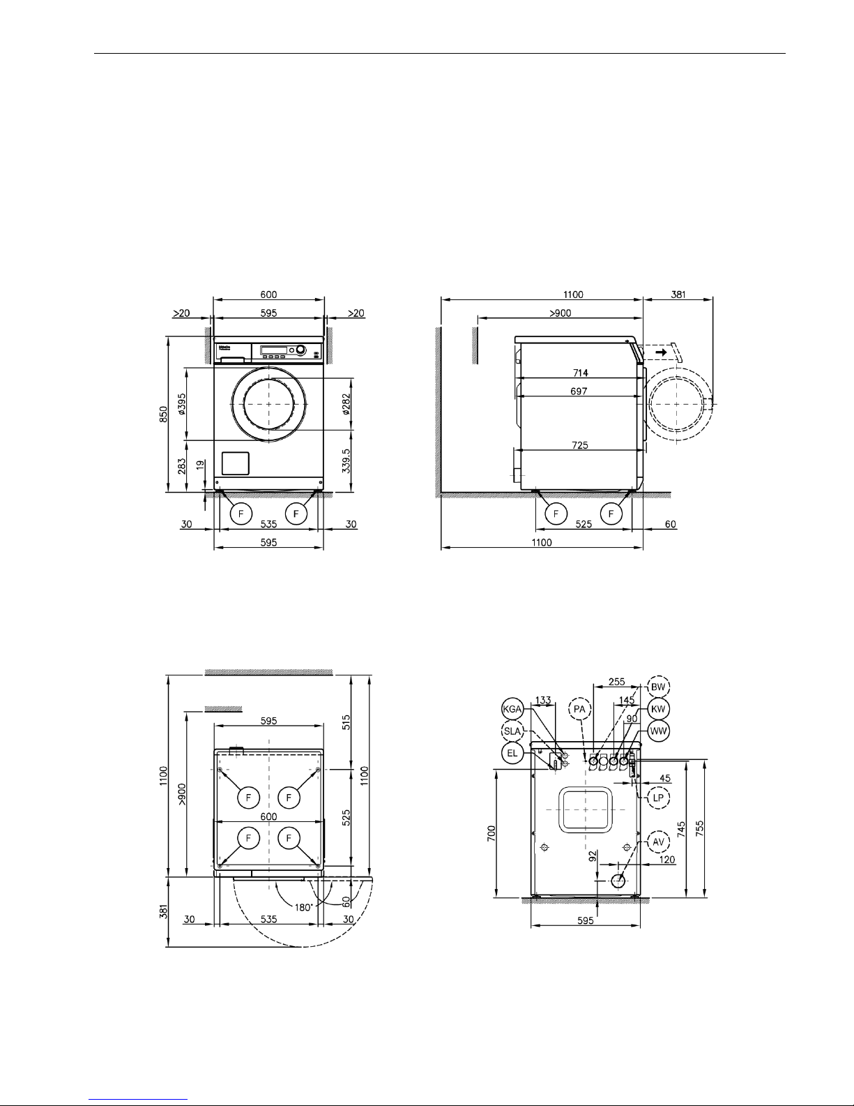
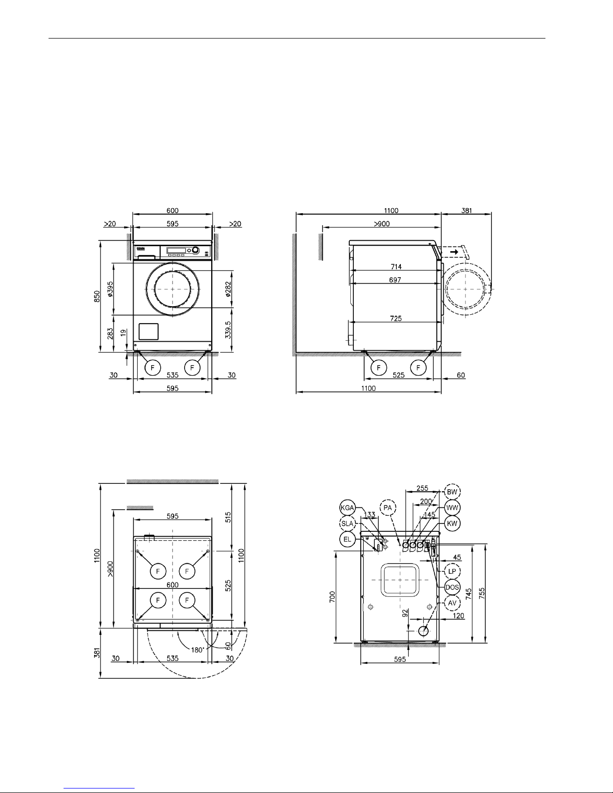
Machine dimensions PW 6055
en – AU, NZ PW 6055/6065
4 10 291 510 / 01
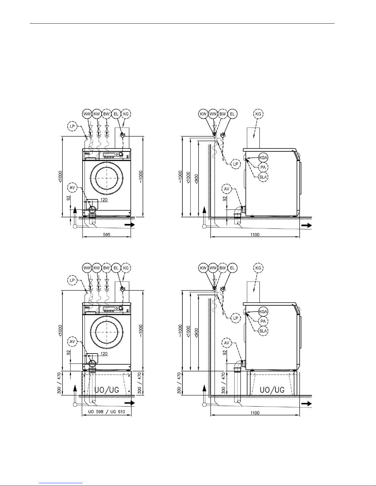
Installation PW 6055
PW 6055/6065 en – AU, NZ
10 291 510 / 01 5
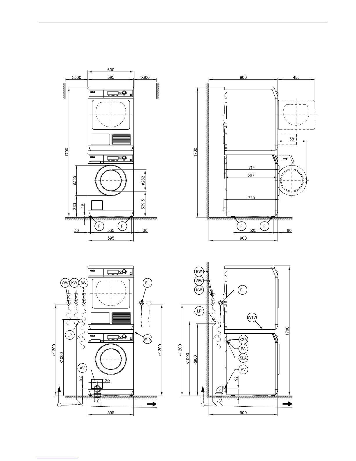
Washer-dryer stack PW 6055
en – AU, NZ PW 6055/6065
6 10 291 510 / 01
Machine dimensions PW 6065

PW 6055/6065 en – AU, NZ
10 291 510 / 01 7
Installation PW 6065

en – AU, NZ PW 6055/6065
8 10 291 510 / 01
Washer-dryer stack PW 6065

PW 6055/6065 en – AU, NZ
10 291 510 / 01 9
Installation

en – AU, NZ PW 6055/6065
10 10 291 510 / 01
Installation

PW 6055/6065 en – AU, NZ
= standard, = optional, + = only on request, - not available
10 291 510 / 01 11
Technical data
PW 6055 AV
PW 6055 LP
PW 6065 AV
PW 6065 LP
Drum volume
l
54
54
59
59
Load capacity
kg
5.5
5.5
6.5
6.5
Door opening diameter
mm
282
282
282
282
Max. spin speed
rpm
1400
1400
1400
1400
g factor
526
526
526
526
Residual moisture (standard load per DIN 60456)
%
49
49
49
49
Electrical connection (EL)
Standard voltage
2N AC 400 V
2N AC 400 V
2N AC 400 V
2N AC 400 V
Frequency
Hz
50
50
50
50
Total rated load
kW
5.5
5.5
5.5
5.5
Fuse rating (B trip rating according to EN 60898)
A
2 x 16
2 x 16
2 x 16
2 x 16
Supply lead min. cross-section
mm²
4 x 1.5
4 x 1.5
4 x 1.5
4 x 1.5
Supply lead without plug for hard-wired connection
Length of supply lead
mm
1800
1800
1800
1800
Alternative voltage (convertible by Service)
1N AC 230 V
1N AC 230 V
1N AC 230 V
1N AC 230 V
Total rated load
kW
2.85
2.85
2.85
2.85
Fuse rating (B trip rating according to EN 60898)
A
1 x 16
1 x 16
1 x 16
1 x 16
Supply lead min. cross-section
mm²
3 x 1.5
3 x 1.5
3 x 1.5
3 x 1.5
Non-standard voltage OS 440 (Offshore)
- -
3 AC 440 V
3 AC 440 V
Frequency
Hz - -
60
60
Total rated load
kW - -
5.05
5.05
Fuse rating (B trip rating according to EN 60898)
A - -
3 x 16
3 x 16
Supply lead min. cross-section
mm² - -
4 x 1.5
4 x 1.5
Supply lead without plug for hard-wired connection
- -
Length of supply lead
mm - -
1800
1800
Non-standard voltage OS 400 (Offshore)
- - - 3 AC 400 V
Frequency
Hz - - - 50
Total rated load
kW - - - 4.2
Fuse rating (B trip rating according to EN 60898)
A - - - 3 x 16
Supply lead min. cross-section
mm² - - - 4 x 1.5
Supply lead without plug for hard-wired connection
- -
- Length of supply lead
mm - - - 2000
Non-standard voltage OS 230 (Offshore)
- - - 3 AC 230 V
Frequency
Hz - - - 60
Total rated load
kW - - - 4.4
Fuse rating (B trip rating according to EN 60898)
A - - - 3 x 16
Supply lead min. cross-section
mm² - - - 4 x 1.5
Supply lead without plug for hard-wired connection
- -
- Length of supply lead
mm - - - 2000
Variations in the following countries:
Standard voltage 13A (GB only)
2N AC 400 V
2N AC 400 V
2N AC 400 V
Frequency
Hz - 50
50
50
Total rated load
kW - 5.5
5.5
5.5
Fuse rating (B trip rating according to EN 60898)
A - 2 x 13
2 x 13
2 x 13
Supply lead min. cross-section
mm² - 4 x 1.5
4 x 1.5
4 x 1.5
Supply lead without plug for hard-wired connection
-
Length of supply lead
mm - 2000
2000
2000
Alternative voltage (convertible)
- 1N AC 230 V
1N AC 230 V
1N AC 230 V
Total rated load
kW - 2.85
2.85
2.85
Fuse rating (B trip rating according to EN 60898)
A - 1 x 13
1 x 13
1 x 13
Supply lead min. cross-section
mm² - 3 x 1.5
3 x 1.5
3 x 1.5

en – AU, NZ PW 6055/6065
= standard, = optional, + = only on request, - not available
12 10 291 510 / 01
Technical data
PW 6055 AV
PW 6055 LP
PW 6065 AV
PW 6065 LP
Standard voltage 13A (GB only)
1N AC 220-240 V
Frequency
Hz - 50 - -
Total rated load
kW - 2.1 - 2.4
- - Fuse rating (B trip rating according to EN 60898)
A - 1 x 13 - -
Supply lead min. cross-section
mm² - 3 x 1.5
- - Supply lead with plug
- - - Length of supply lead
mm - 2000 - -
Standard voltage 25A (GB only)
1N AC 220-240 V
1N AC 220-240 V
1N AC 220-240 V
1N AC 220-240 V
Frequency
Hz
50
50
50
50
Total rated load
kW
5.05 - 6.0
5.05 - 6.0
5.05 - 6.0
5.05 - 6.0
Fuse rating (B trip rating according to EN 60898)
A
1 x 25
1 x 25
1 x 25
1 x 25
Supply lead min. cross-section
mm²
3 x 2.5
3 x 2.5
3 x 2.5
3 x 2.5
Supply lead without plug for hard-wired connection
Length of supply lead
mm
2000
2000
2000
2000
Standard voltage (CH, DK, S only)
3N AC 400 V
3N AC 400 V
3N AC 400 V
3N AC 400 V
Frequency
Hz
50
50
50
50
Total rated load
kW
4.8
4.8
4.8
4.8
Fuse rating (B trip rating according to EN 60898)
A
3 x 10
3 x 10
3 x 10
3 x 10
Supply lead min. cross-section
mm²
5 x 1.5
5 x 1.5
5 x 1.5
5 x 1.5
Supply lead without plug for hard-wired connection
Length of supply lead
mm
2000
2000
2000
2000
Standard voltage (B only)
3 AC 230 V
3 AC 230 V
Frequency
Hz - -
50
50
Total rated load
kW - -
5.5
5.5
Fuse rating (B trip rating according to EN 60898)
A - -
3 x 20
3 x 20
Supply lead min. cross-section
mm² - -
4 x 2.5
4 x 2.5
Supply lead without plug for hard-wired connection
-
-
Length of supply lead
mm - -
2000
2000
Alternative voltage (convertible)
- -
2N AC 400 V
2N AC 400 V
Total rated load
kW - -
5.5
5.5
Fuse rating (B trip rating according to EN 60898)
A - -
2 x 16
2 x 16
Supply lead min. cross-section
mm² - -
4 x 1.5
4 x 1.5
Alternative voltage (convertible)
- -
1N AC 230
1N AC 230
Total rated load
kW - -
2.85
2.85
Fuse rating (B trip rating according to EN 60898)
A - -
1 x 16
1 x 16
Supply lead min. cross-section
mm² - -
3 x 1.5
3 x 1.5
Standard voltage (N only)
1N AC 220-240 V
1N AC 220-240 V
1N AC 220-240 V
1N AC 220-240 V
Frequency
Hz
50
50
50
50
Total rated load
kW
2.9 - 3.45
2.9 - 3.45
2.9 - 3.45
2.9 - 3.45
Fuse rating (B trip rating according to EN 60898)
A
1 x 16
1 x 16
1 x 16
1 x 16
Supply lead min. cross-section
mm²
3 x 1.5
3 x 1.5
3 x 1.5
3 x 1.5
Supply lead with plug
Length of supply lead
mm
2000
2000
2000
2000
Standard voltage (AUS only)
1N AC 220-240 V
1N AC 220-240 V
Frequency
Hz - -
50
50
Total rated load
kW - -
5.05 - 6.0
5.05 - 6.0
Fuse rating
A - -
1 x 25
1 x 25
Supply lead min. cross-section
mm² - -
3 x 2.5
3 x 2.5
Supply lead without plug for hard-wired connection
-
-
Length of supply lead
mm - -
2000
2000

PW 6055/6065 en – AU, NZ
= standard, = optional, + = only on request, - not available
10 291 510 / 01 13
Technical data
PW 6055 AV
PW 6055 LP
PW 6065 AV
PW 6065 LP
Standard voltage (CDN only)
- - - 2 AC 208 V
Frequency
Hz - - - 60
Total rated load
kW - - - 4.0
Fuse rating
A - - - 2 x 20
Supply lead min. cross-section
mm² - - - 4 x AWG 10
Supply lead without plug for hard-wired connection
- -
- Length of supply lead
mm - - - 2000
Standard voltage (USA only)
- - - 2 AC 208-240 V
Frequency
Hz - - - 60
Total rated load
kW - - - 4.0
Fuse rating
A - - - 2 x 30
Supply lead min. cross-section
mm² - - - 4 x AWG 10
Supply lead without plug for hard-wired connection
- -
- Length of supply lead
mm - - - 2000
Cold water (KW)
Permissible water flow pressure
kPa
100 - 1000
100 - 1000
100 - 1000
100 - 1000
Required flow rate (cold water connection only)
l/min
11
11
11
11
Required flow rate (with additional hot water connection)
l/min
10
10
10
10
Average water consumption (60°C standard programme)
l/h
36
36
40
40
Connection to be provided on site, external thread according to AS 3688
Inch
¾“
¾“
¾“
¾“
Connection hose ½“ with ¾“ threaded union
Connection hose length
mm
1550
1550
1550
1550
Hot water (WW)
Max. water intake temperature
°C
70
70
70
70
Permissible water flow pressure
kPa
100 - 1000
100 - 1000
100 - 1000
100 - 1000
Min. flow rate
l/min
11
11
11
11
Average water consumption (60°C standard programme)
l/h
13
13
13
13
Connection to be provided on site, external thread according to AS 3688
Inch
¾“
¾“
¾“
¾“
Connection hose ½“ with ¾“ threaded union
Connection hose length
mm
1550
1550
1550
1550
Alternative water supply (BW)
Kit with additional inlet valve
Permissible water flow pressure
kPa
100 - 1000
100 - 1000
100 - 1000
100 - 1000
Min. flow rate
l/min
11
11
11
11
Average water consumption (60°C standard programme)
l/h
14
14
17
17
Connection to be provided on site, external thread according to AS 3688
Inch
¾“
¾“
¾“
¾“
Connection hose ½“ with ¾“ threaded union
Connection hose length
mm
1550
1550
1550
1550
Drain valve (AV)
Connection (ext. diameter)
mm
75 (DN70)
-
75 (DN70)
-
Drainage temperature, max.
°C
90 90 Max. transient flow rate
l/min
62 - 62 -
Drain pump (LP)
Hose connection (external diameter)
mm - 22 (DN22)
-
22 (DN22)
Drainage temperature, max.
°C - 90 - 90
On-site hose sleeve (int. diameter x length)
mm - 22 x 30
-
22 x 30
Max. transient flow rate
l/min - 26 - 26
Max. head height (from lower edge of machine)
mm - 1000 - 1000
Drain hose DN 22 with connector (supplied as standard)
- -
Connection hose length
mm - 1500 - 1500
Equipotential bonding (PA)
Machine connection (separate kit required)

en – AU, NZ PW 6055/6065
= standard, = optional, + = only on request, - not available
14 10 291 510 / 01
Technical data
PW 6055 AV
PW 6055 LP
PW 6065 AV
PW 6065 LP
Peak load / Energy management (SLA)
Machine connection (separate kit required)
Control signal voltage
AC 230 V
AC 230 V
AC 230 V
AC 230 V
Payment system connection (KGA)
Connection of payment systems
Communication module (XKM)
RS 232 serial interface (XKM module retrofitting kit)
Liquid dispensing (DOS)
Connection for liquid detergents (conversion kit required)
- - Connection for liquid detergents
- -
No. of dispenser pumps, max.
No. 6 6 6 6
Installation on machine feet (F)
No. of machine feet
No. 4 4 4 4
Machine foot, height-adjustable with thread
mm
±4
±4
±4
±4
Machine foot diameter
mm
40
40
40
40
Anchoring (B)
Standard anchoring
Floor anchor kit (for 2 machine feet)
Wood screws according to DIN 571
mm
6 x 50
6 x 50
6 x 50
6 x 50
Rawl plugs (diameter x length)
mm
8 x 40
8 x 40
8 x 40
8 x 40
Anchoring of Miele plinths
Accessory: Miele plinth (fasteners included)
Required anchor points
No. 4 4 4 4
Wood screws according to DIN 571
mm
8 x 65
8 x 65
8 x 65
8 x 65
Rawl plugs (diameter x length)
mm
12 x 60
12 x 60
12 x 60
12 x 60
Plinth floor anchoring (to be provided on site)
Machine installation on permanent plinth (concrete or masonry)
Plinth installation footprint (W/D)
mm
600/650
600/650
600/650
600/650
Wood screws according to DIN 571
mm
6 x 50
6 x 50
6 x 50
6 x 50
Rawl plugs (diameter x length)
mm
8 x 40
8 x 40
8 x 40
8 x 40
Machine data
Overall machine dimensions (H/W/D)
mm
850/600/722
850/605/715
850/600/722
850/605/715
Casing dimensions (H/W/D)
mm
850/595/697
850/595/697
850/595/697
850/595/697
Site-access dimensions (H/W)
Min. site-access (excl. packaging)
mm
900/600
900/600
900/600
900/600
Installation dimensions
Min. side gap
mm
20
20
20
20
Recommended side gap - washer-dryer stack
mm
>300
>300
>300
>300
Min. distance to opposite wall from front of machine
mm
900
900
900
900
Recommended distance to opposite wall from front of machine
mm
1100
1100
1100
1100
Weights and floor loads
Machine weight (net weight)
kg
106
106
109
109
Max. floor load in operation
N
2820
2820
2820
2820
Max. floor load, static
N
1380
1380
1455
1455
Max. floor load, dynamic
N
1365
1365
1365
1365
Max. drum rotation frequency
Hz
22
22
22
22
Emissions
Sound pressure level in accordance with EN ISO 11204/11203
dB(A)
<70
<70
<70
<70
Heat dissipation rate to installation site
W
250
250
250
250

PW 6055/6065 en – AU, NZ
= standard, = optional, + = only on request, - not available
10 291 510 / 01 15
Options / Accessories
Features
Box plinth (UG)
Box plinth, H 300 mm (UG 5005)
Galvanised plinth, stainless-steel sides
Box plinth, H 470 mm (UG 5005-47)
Galvanised plinth, octoblue stove-finished side panels
Box plinth, H 750mm (UG 5005-75)
Galvanised plinth, octoblue stove-finished side panels
Open plinth (UO)
Open plinth, H 300 mm (UO 5005)
Galvanised plinth, octoblue stove finish
Open plinth, H 470 mm (UO 5005-47)
Galvanised plinth, octoblue stove finish
Washer-dryer stacking kit (WTV)
Stainless-steel kit (WTV 5062)
Washer-dryer stacking kit
Lotus white kit (WTV 5061)
Washer-dryer stacking kit
Payment systems (KG)
Single unit (C 4060)
Payment system for tokens (programme operation only)
Single unit (C 4065)
Payment system for euro coins, time and programme operation
Single unit (C 4070)
Payment system for tokens and euro coins, time and programme operation
Multi-machine unit (C 5200 BT)
Base unit for GeldKarte transactions (for max. 8 machines)
Remote bundle (ABT 5220)
Machine monitoring with Bluetooth communication (one each per machine)
Accessories
Connection of peak-load/energy management (BSS)
Connection for peak-load and energy management functionalities
Equipotential bonding kit
The conversion kit is available from Miele
Communication module XKM (XKM RS 232-10)
Retrofitting kit XKM module with RS 232, including building-in kit

en – AU, NZ PW 6055/6065
16 10 291 510 / 01
Installation and planning notes
Installation requirements
Electrical connection should only be made to a power supply provided
in accordance with all appropriate local and national legislation and
regulations.
In addition, all regulations issued by the appropriate utilities as well as
standards relating to occupational safety, and all applicable valid
regulations and technical standards must be observed.
Transportation and site access
The machine must not be moved without the transit bars in place.
Keep the transit bars in a safe place. They must be refitted if the
machine is to be moved again (e.g. when relocating the machine).
General operating conditions
Ambient temperature in installation room: +2°C to +35°C.
Depending on the nature of the installation site, sound emissions and
vibration may occur. Miele recommends consulting a specialist if
particular requirements apply at the installation site with respect to
sound emissions.
Electrical connection
Depending on the model, the machine is delivered with a supply lead
with/without a plug.
The washer may only be connected to an electrical system that
conforms to the national and local codes and regulations. The
installation must be performed by a qualified electrician.
The machine data plate indicates the nominal power consumption and
the appropriate fuse capacity. Compare the specifications on the data
plate with those of the electrical power supply.
The machine can be hard-wired or connected using a switched
connection in accordance with IEC 60309-1 or AS/NZS 3000. It is
always recommended to make electrical connection via a plug and
socket so that electrical safety checks, e.g. during repair or service
work, can be carried out easily.
If the machine is hard wired, a dual circuit breaker must be provided
on-site. When switched off, there must be an all-pole contact gap of 3
mm in the isolator switch (including switch, fuses and relays according
to IEC/EN 60947 or AS/NZS 3000).
The plug connectors or isolator switch should be easily accessible for
servicing work. If the machine is disconnected from the electricity
supply, ensure adequate measures are taken to ensure that the
machine cannot be reconnected to the electricity supply until all work
has been carried out.
New connections, modifications to the system or servicing of the
ground conductor, including determining the correct fuse amperage,
must be carried out by a qualified electrician, as they are familiar with
the pertinent regulations and the specific requirements of the
electricity supplier.
If converting the machine to an alternative voltage, observe the
instructions in the wiring diagram. Conversion must be performed
by an authorised agent or a Miele service technician. The heater
rating must also be properly set.
The machine must be permanently connected to the electricity supply
so that the door can be opened. For this reason, it must not be
connected to devices such as timers which would switch it off
automatically.
References to cable cross-sections in the technical data refer only to
the required supply lead. Please consult relevant local and national
regulations when calculating any other wire gauges.
Cold water connection
The machine should be connected to a mains water supply in
accordance with current local and national regulations on water
safety.
IMPORTANT: Australia and New Zealand
This appliance must be installed according to AS/NZS 3500.1. This
appliance has been supplied with a separate backflow prevention
device.
Add drawing and instructions as per below for installing the non-return
valve
• Disconnect the mains (switch off or unplug the power).
• Turn off the water tap.
• Place the seals on both sides of the non-return valve.
• Connect the female of the non-retun valve to the tap (G3/4” thread).
• Connect the hose to the male end of the no-return valve (G3/4”
thread).
• Turn on the tap gradually to test for leaks. If there is a leak, the
connection might not be on securely, or it may have been screwed on
at an angle. Unscrew and reconnect the water correctly before
tightening it.
Connection to the water supply should be carried out by a qualified
plumber using a tap with a threaded union. If a tap is not available, a
qualified plumber should connect the machine to the water supply.
A suitable connection hose with a threaded union is provided with the
machine.
Longer hoses (2.5 or 4.0 m in length) are available from Spares as
separate items.
The hoses must be connected after the non-return valve.
Hot water connection
The same connection requirements as for cold water also apply to hot
water (max. 70°C).
A suitable connection hose with a threaded union is provided with the
machine.
The machine can be connected to a hot water supply of 70°C to max.
85°C. This requires the use of a separate heat-resistant inlet hose.
This additional hose must be obtained from Miele. In addition, the
appliance must be programmed accordingly by a Miele service
technician or an authorised agent.
Connection to hot water only is not possible for functional reasons.
In the event that hot water is not available on site, connection of the
second hose must be made to a cold water supply.
Alternatively, the hot water connection should be blocked using the
enclosed blind stopper and the machine controls set to cold water
intake.
The required amount of hot water should be added to the cold water
volume.
Grey water connection
The connection of an alternative type of water is optional and requires
the use of an additional kit.
The same requirements apply as for the cold water connection.
Drain valve (depending on model)
The washing machine is drained using a motorised drain valve. The
machine can be connected directly to the on-site drainage system
(without an odour trap) or via a floor drain (floor drain with odour trap).
A vented drainage system is vital for unimpeded drainage. If on-site
venting is insufficient, a vent kit (Mat. no. 05239540) is available from
Miele.
If several machines are connected to a single drain pipe, this should
be sufficiently large to allow all machines to drain simultaneously.
Drain pump (depending on model)
The machine drains through a pump with a 1 m delivery head. For the
water to drain freely, the hose must be free of kinks. The swivel elbow
at the end of the hose can be turned in either direction, or removed as
needed with a sharp twist and pull.
Drain hose connection:
1. Connected securely to a trapped waste pipe with a rubber sleeve.
2. Connected over the rim of the laundry trough or into the sud-saver
pipe of the laundry trough.
3. Connected securely to a waste pipe connected to the floor waste
gully.

PW 6055/6065 en – AU, NZ
10 291 510 / 01 17
Trade waste discharge from commercial clothes washer may require
pre-treatment as determined by the network utility operator.
Connecting the drain hose to a sink drain outlet
The drain hose with non-return valve fitted can be connected securely
to a suitable sink drain outlet.
If required, the hose can be extended to a length of 5 m. The
necessary parts can be ordered from Miele.
For a delivery head of more than 1 m (up to a max. of 1.6 m) a
replacement drain pump will need to be fitted. Please contact Miele for
advice.
Equipotential bonding
If necessary, equipotential bonding with good galvanic contact must
be guaranteed in compliance with all applicable local and national
installation specifications.
Connection material for equipotential bonding must be provided on
site or using a kit available from Miele.
Peak load / Energy management
The machine can be connected to a peak-load or energy
management system using an optional kit.
Three signals are issued by the machine via a terminal strip. The
terminal strip is labelled a, b, c, and d.
a - Output signal, Start of machine operation
b - Output signal, Machine heating request
c - Peak-load input signal, Machine heating deactivated
d - Neutral conductor
When a peak-load signal is received, the heating is deactivated and
the programme stopped. An appropriate message appears in the
display.
The programme is resumed automatically when the peak-load system
reactivates the heating.
Liquid dispensing connection
External liquid dispenser pumps with a 'container empty' indicator can
be used to dispense liquid detergents.
Only liquid dispenser pumps with their own controls or
programming facilities can be used.
It is particularly important to observe manufacturer's instructions when
using a combination of detergents, additives and special-purpose
products.
Payment system
This machine can be fitted with a single-machine payment system
(optional accessory). The necessary programming should only be
performed by a qualified agent or by Miele.
Alternatively, a wireless multi-machine system for a maximum of 8
units can be connected to a Geldkarte payment system and further
controls used to monitor machines.
Serial interface
The serial interface is provided by an additional XKM RS323 module.
The led through data interface from the XKM RS232 module conforms
with SELV (safety extra-low voltage) according to EN 60950. External
connection units must also comply with SELV.
The plug-in module is provided with a connection cable and a D-Sub
plug for connection.
Installation and anchoring
The machine must be installed on a perfectly smooth, level and firm
surface which is able to withstand the quoted loads.
The floor load created by the machine is concentrated and transferred
to the installation footprint via the machine feet.
The machine must be secured to its installation location.
The machine should be levelled in both directions with the aid of the
adjustable feet.
The anchors provided can be used to bolt the machine to the floor by
both front feet. The material provided is intended for use in bolting the
machine to a concrete floor.
Bolts and fasteners for all other floor types must be provided on site.
Plinth installation
The machine can be installed on a machine plinth (open or box plinth,
available as an optional Miele accessory) or on a concrete platform to
be provided on site.
The quality of the concrete and its strength must be assessed
according to the machine load. Ensure that any raised concrete plinth
is adequately bonded to the concrete floor below.
If the machine is installed on a concrete or masonry plinth, it must be
secured using the anchors supplied with the machine. Otherwise there
is the danger of the machine moving and falling off the plinth during
spinning.
Washer-dryer stack
This washing machine can be installed with a Miele tumble dryer on
top of it. A WTV stacking kit (optional accessory) is required for this.
Installation of the stacking kit must be performed by a Miele service
technician or an authorised agent.
 Loading...