

Page 1
Umbau- und Montageanweisung
1
2
3
4
5
6
7
8
9
10
11
12
13
14
M.-Nr. 11012340 1 von 16
de Sockel fest (FP) en Fixed plinth (FP) cs Pevný sokl (FP) el Σταθερή Βάση (FP) en-USPermanent stand (FP) es Zócalo fijo(FP)
fr Socle fixe (FP) it Zoccolo fisso (FP) nl Vaste sokkel (FP)
no Fast sokkel (FP) pt Base fixa (FP) ru Неподвижное основание (FP)
sv Fast sockel (FP)
1
de
Sockel fest (FP)
Grund: Dieser Umbausatz dient dazu, die Option Sockel fest (FP) an Geräte vom Typ PLW8615, PLW8616, PLW8617,
PWD8626, PWD8628 anzubauen.
Diese Unterlagen dürfen ohne unsere Genehmigung weder vervielfältigt noch Dritten zugänglich gemacht werden. Eigentumsrechte vorbehalten. 08.03.2019
Page 2

Umbau- und Montageanweisung
2 von 16 M.-Nr. 11012340
Die Verwendung mit Geräten mit nur einer Tür der Typen PLW8615, PLW8617 ist nur möglich, wenn die Rückseite des
Geräts zugänglich ist.
Der Sockel kann für die Ablaufarten Ablaufventil und Ablaufpumpe eingesetzt werden.
Die Option Sockel fest (FP) kann nur bei Geräten verbaut werden, die von beiden Seiten zugänglich sind. Bei der Option
Sockel fest (FP) können die Ablaufarten Ablaufventil und Ablaufpumpe verwendet werden.
Für die benötigten Anschlüsse, Abläufe und Zuläufe den Installationsplan beachten.
– FP900 = geeignet für 900 mm breite Geräte vom Typ: PLW8615, PLW8616, PWD8626
– FP1150 = geeignet für 1150 mm breite Geräte vom Typ: PLW8617, PWD8628
Benötigte Teile
Anzahl M.-Nr. Benennung
1 10941870 FP900 - Sockel fest (Fixed Plinth = FP) 900 mm
1 10880750 FP1150 - Sockel fest (Fixed Plinth = FP) 1150 mm
Für die Durchführung der Instandhaltungsarbeiten am Gerät ist die Miele Service-Applikation „Technische Service Dokumentation (TSD)“ erforderlich
Die Sicherheits- und Warnhinweise der für den Gerätetyp geltenden Typ-TSD müssen beachtet werden.
Die Arbeiten am Gerät müssen entsprechend der für den Gerätetyp geltenden Arbeitsanleitungen durchgeführt werden.
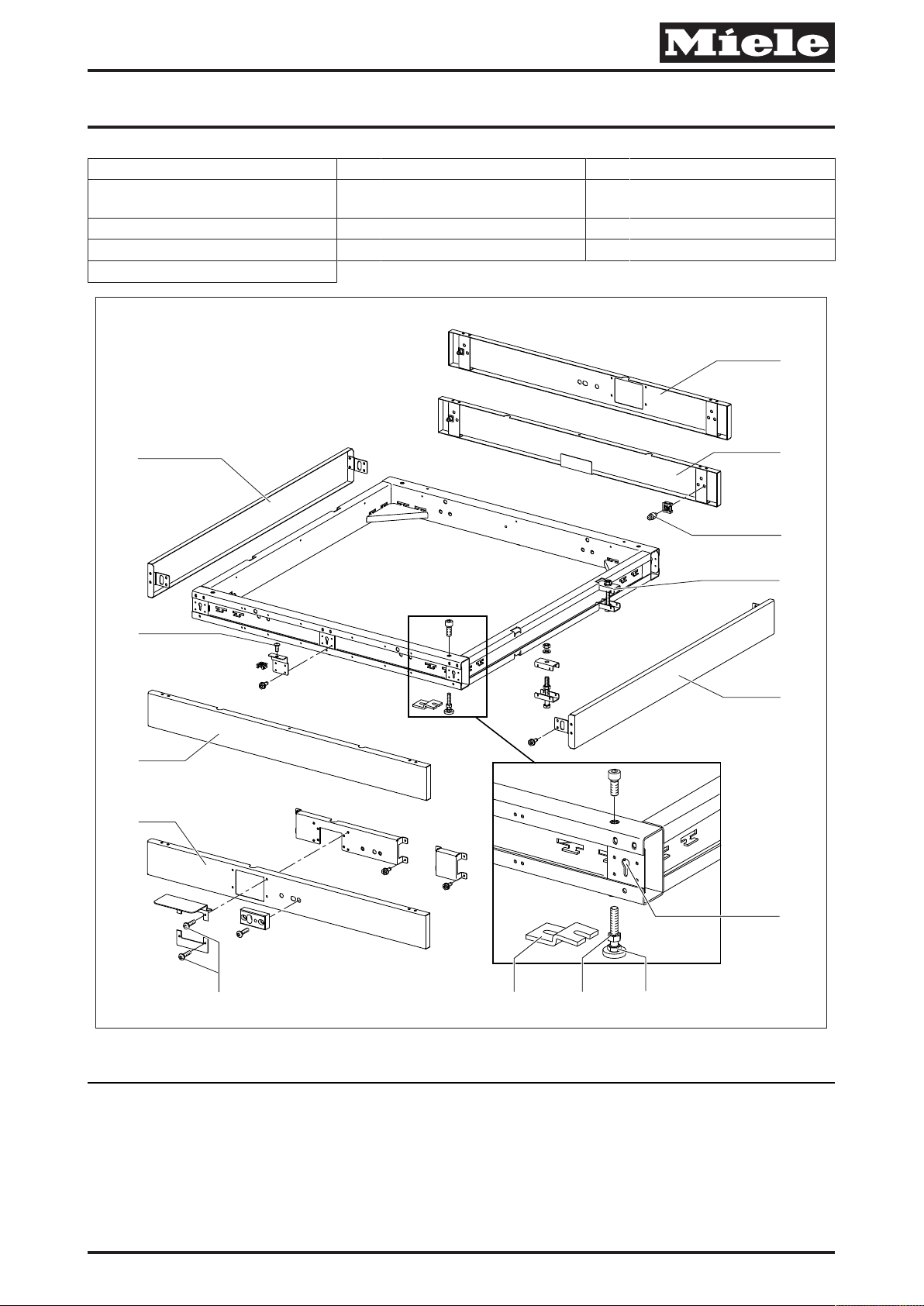
Sockel fest (FP) aufbauen
Sockelblende abbauen
Um den Sockel auszurichten, muss auf der Beladeseite und Entladeseite jeweils die Sockelblende abgebaut werden.
A Bei festem Sockel mit Transportbandanschluss-Ausschnitt: Die 4 Befestigungsschrauben (5) um den Ausschnitt
des Transportbandanschlusses herausdrehen, siehe Abb. 1.
A Bei festem Sockel ohne Transportbandanschluss-Ausschnitt: Die Befestigungsschrauben (2) in der Mitte der
Sockelblende von oben lösen, siehe Abb. 1.
A Sockelblende (4), (5), (13) oder (14) anheben und aus dem Schlüssellochhalterungen (9) heben, siehe Abb. 1.
Sockel ausrichten
A Sockel aufstellen und durch Hochdrehen oder Herunterdrehen der Füße (8) waagerecht ausrichten, siehe Abb. 1.
A Nachdem der Sockel waagerecht ausgerichtet ist, Kontermuttern (7) der Füße festdrehen, siehe Abb. 1.
A Bei Reihenaufstellung von mehreren Geräten darauf achten, dass die Sockelbodenwannen absolut gleichmäßig
ausgerichtet sind.
A Zusätzlich die Sockel untereinander mit der Klammer (11) verbinden, siehe Abb. 1.
Optional Bodenbefestigungen anbauen
Die Bodenbefestigungen (6) dienen dazu, das Gerät gegen Umfallen z.B. bei Erdbeben zu sichern, siehe Abb. 1.
A Bohrungen für die Bodenbefestigung der Sockelbodenwanne anzeichnen.
A Bohrungen für die Dübel bohren.
A Bohrstaub aus den Bohrungen entfernen.
A Die mitgelieferten Dübel in die Bohrungen einsetzen.
Die mitgelieferten Spezialdübel dichten später das Bohrloch wieder gegen eindringende Feuchtigkeit ab.
A Die Bodenbefestigungen mit den Befestigungsschrauben festschrauben.
de
08.03.2019 Diese Unterlagen dürfen ohne unsere Genehmigung weder vervielfältigt noch Dritten zugänglich gemacht werden. Eigentumsrechte vorbehalten.
Page 3

Umbau- und Montageanweisung
M.-Nr. 11012340 3 von 16
en
Fixed plinth (FP)
Reason: This conversion kit enables the fixed plinth (FP) option to be fitted to PLW8615, PLW8616, PLW8617,
PWD8626 and PWD8628 machines.
It can only be used with PLW8615 or PLW8617 models with just one door if the rear of the appliance can be
accessed.
The plinth can be used for drain valve and drain pump drainage solutions.
The fixed plinth (FP) option can only be fitted to machines that can be accessed from both sides. Drain valve and drain
pump drainage solutions can be used with the fixed plinth (FP) option.
Please refer to the installation plan for the required connections, drains and infeeds.
– FP900 = suitable for 900mm wide machines: PLW8615, PLW8616, PWD8626
– FP1150 = suitable for 1150mm wide machines: PLW8617, PWD8628
Parts required
No. Mat. no. Designation
1 10941870 FP900 – Fixed plinth (FP) 900mm
1 10880750 FP1150 – Fixed plinth (FP) 1150mm
In order to carry out this work, the appropriate Technical Service Documentation (TSD) is required.
The warning and safety instructions given in the applicable model-specific TSD must be complied with.
Work must be carried out in accordance with the instructions given in the applicable model-specific TSD.
Fitting the fixed plinth (FP)
Removing the plinth panel
To level the plinth, remove the plinth panel on both the infeed side and the outfeed side.
A Fixed plinth with cutout for attaching a transport conveyor: Unscrew the 4 fixing screws (5) around the cutout for
attaching a conveyor, see Fig. 1.
A Fixed plinth without cutout for attaching a transport conveyor: Unscrew the fixing screws (2) in the centre of the
plinth panel from above, see Fig. 1.
A Lift the plinth panel (4), (5), (13) or (14) up and out of the keyhole brackets (9), see Fig. 1.
Levelling the plinth
A Fit the plinth and level it by adjusting the feet (8) up or down, see Fig. 1.
A Once the plinth is level, tighten the counter nuts (7) on the feet, see Fig. 1.
A If you are installing several machines side by side, make sure that the plinth drip trays are aligned absolutely level.
A Also use the clamp (11) to connect the individual plinths together, see Fig. 1.
Fitting optional floor mounts
The floor mounts (6) help to protect the machine in the event of an earthquake, forexample, see Fig. 1.
A Mark out drill holes for the floor mount on the plinth drip tray.
A Drill holes for the plugs.
A Remove the drilling dust from the holes.
A Insert the plugs supplied with the mounts into the holes.
Diese Unterlagen dürfen ohne unsere Genehmigung weder vervielfältigt noch Dritten zugänglich gemacht werden. Eigentumsrechte vorbehalten. 08.03.2019
Page 4

Umbau- und Montageanweisung
4 von 16 M.-Nr. 11012340
The special plugs supplied with the mounts will subsequently seal the drilled hole to prevent the ingress of moisture.
A Secure the floor mounts with the fixing screws.
en
cs
Pevný sokl (FP)
Důvod: Tato montážní sada slouží knamontování volby pevný sokl (FP) na přístroje typu PLW8615, PLW8616,
PLW8617, PWD8626, PWD8628.
Použití spřístroji jen sjedněmi dvířky typů PLW8615, PLW8617 je možné jen tehdy, když je přístupná zadní strana
přístroje.
Sokl lze použít pro způsoby vypouštění vypouštěcí ventil ivypouštěcí čerpadlo.
Volbu pevný sokl (FP) lze montovat jen upřístrojů, které jsou přístupné zobou stran. Uvolby pevný sokl (FP) se mohou
používat způsoby vypouštění vypouštěcí ventil ivypouštěcí čerpadlo.
Ohledně potřebných přípojů, odtoků a přítoků respektujte instalační plán.
– FP900 = vhodný pro přístroje šířky 900mm typu PLW8615, PLW8616, PWD8626
– FP1150 = vhodný pro přístroje šířky 1150mm typu PLW8617, PWD8628
Potřebné díly
Počet č. m. Název
1 10941870 FP900 - pevný sokl (Fixed Plinth = FP) 900 mm
1 10880750 FP1150 - pevný sokl (Fixed Plinth = FP) 1150 mm
Pro provádění údržbářských prací na přístroji je potřebná servisní aplikace Miele „Technická servisní dokumentace (TSD)“
Musí být respektovány bezpečnostní pokyny a varovná upozornění typové TSD platné pro typ přístroje.
Práce na přístroji musí být prováděny podle pracovních návodů platných pro typ přístroje.
Montáž pevného soklu (FP)
Demontáž panelu soklu
Pro vyrovnání soklu je nutné na straně plnění ina straně vyprazdňování odmontovat panel soklu.
A Upevného soklu svýřezem pro připojení pásového dopravníku: Vyšroubujte 4upevňovací šrouby (5) kolem
výřezu pro připojení pásového dopravníku, viz obr. 1.
A Upevného soklu bez výřezu pro připojení pásového dopravníku: Vyšroubujte shora upevňovací šrouby (2)
uprostřed panelu soklu, viz obr. 1.
A Pozvedněte panel soklu (4), (5), (13) nebo (14) a vyzvedněte ho zdržáků sotvorem tvaru klíčové dírky (9), viz obr. 1.
Vyrovnání soklu
A Sokl postavte a vyšroubováním nebo zašroubováním noh (8) ho vodorovně vyrovnejte, viz obr. 1.
A Po vyrovnání soklu do vodorovné polohy utáhněte kontramatice (7) noh, viz obr. 1.
A Při umístění několika přístrojů vřadě dbejte na to, aby byly absolutně rovnoměrně vyrovnané spodní vany soklů.
A Navíc sokly spojte navzájem svorkou (11), viz obr. 1.
Volitelná montáž podlahových příchytek
Podlahové příchytky (6) slouží kzajištění přístroje proti převrácení například při zemětřesení, viz obr. 1.
08.03.2019 Diese Unterlagen dürfen ohne unsere Genehmigung weder vervielfältigt noch Dritten zugänglich gemacht werden. Eigentumsrechte vorbehalten.
Page 5

Umbau- und Montageanweisung
M.-Nr. 11012340 5 von 16
A Orýsujte díry pro upevnění spodní vany soklu na zemi.
A Vyvrtejte díry pro hmoždinky.
A Odstraňte zděr prach zvrtání.
A Nasaďte do děr dodané hmoždinky.
Dodané speciální hmoždinky později vyvrtanou díru zase utěsní proti vnikání vlhkosti.
A Přišroubujte podlahové příchytky upevňovacími šrouby.
cs
el
Σταθερή Βάση (FP)
Αιτία: Το συγκεκριμένο σετ μετατροπής εξυπηρετεί στην τοποθέτηση της επιλογής Σταθερή Βάση (FP) στις συσκευές
τύπου PLW8615, PLW8616, PLW8617, PWD8626, PWD8628.
Η χρήση του με συσκευές μόνο με μία πόρτα τύπου PLW8615, PLW8617 είναι δυνατή μόνο στην περίπτωση που
υπάρχει πρόσβαση από την πίσω πλευρά της συσκευής.
Η βάση μπορεί να τοποθετηθεί για είδη αποχέτευσης, βαλβίδα αποχέτευσης και αντλία αποχέτευσης.
Η επιλογή Σταθερή Βάση (FP) μπορεί να τοποθετηθεί μόνο σε συσκευές, στις οποίες υπάρχει πρόσβαση και από τις δύο
πλευρές. Στην επιλογή Σταθερή Βάση (FP) μπορούν να χρησιμοποιηθούν τα είδη αποχέτευσης, βαλβίδα αποχέτευσης
και αντλία αποχέτευσης.
Λάβετε υπόψη σας τις απαραίτητες συνδέσεις, αποχετεύσεις, παροχές και το σχέδιο εγκατάστασης.
– FP900 = κατάλληλο για συσκευές με πλάτος 900mm τύπου: PLW8615, PLW8616, PWD8626
– FP1150 = κατάλληλο για συσκευές με πλάτος 1150mm τύπου: PLW8617, PWD8628
Αναγκαία μέρη
Αριθμός Κωδικός
προϊόντος
1 10941870 FP900 – Σταθερή Βάση (Fixed Plinth = FP) 900mm
1 10880750 FP1150 – Σταθερή Βάση (Fixed Plinth = FP) 1150mm
Για τη διεξαγωγή των εργασιών συντήρησης στη συσκευή είναι απαραίτητη η εφαρμογή του Miele Service «Τεχνική Τεκμηρίωση Service (TSD)»
Πρέπει να λαμβάνονται υπόψη οι υποδείξεις ασφαλείας και προειδοποιήσεις του Typ-TSD που ισχύει για το μοντέλο
της συσκευής.
Οι εργασίες στη συσκευή πρέπει να διεξάγονται σύμφωνα με τις οδηγίες για την εργασία που ισχύουν για το μοντέλο της
συσκευής.
Τοποθέτηση Σταθερής Βάσης (FP)
Αφαίρεση μετόπης σοβατεπί
Για να ευθυγραμμίσετε τη βάση πρέπει να αφαιρεθεί η μετόπη σοβατεπί αντίστοιχα από την πλευρά φόρτωσης και από
την πλευρά εκφόρτωσης.
Ονομασία
A Σε σταθερή βάση με άνοιγμα σύνδεσης ιμάντα μεταφοράς: Βιδώστε τις 4βίδες στερέωσης(5) στο άνοιγμα
σύνδεσης ιμάντα μεταφοράς, βλέπε εικ.1.
A Σε σταθερή βάση χωρίς άνοιγμα σύνδεσης ιμάντα μεταφοράς: Αφαιρέστε από πάνω τις βίδες στερέωσης(2) στη
μέση της μετόπης σοβατεπί, βλέπε εικ.1.
A Ανασηκώστε τη μετόπη σοβατεπί(4), (5), (13) ή (14) και σηκώστε τα στηρίγματα σε σχήμα κλειδαρότρυπας(9), βλέπε
εικ.1.
Diese Unterlagen dürfen ohne unsere Genehmigung weder vervielfältigt noch Dritten zugänglich gemacht werden. Eigentumsrechte vorbehalten. 08.03.2019
Page 6

Umbau- und Montageanweisung
6 von 16 M.-Nr. 11012340
Ευθυγράμμιση βάσης
A Τοποθετήστε τη βάση και ευθυγραμμίστε οριζόντια βιδώνοντας προς τα πάνω ή προς τα κάτω τα πέλματα(8), βλέπε
εικ.1.
A Αφού η βάση ευθυγραμμιστεί οριζόντια, βιδώστε σφικτά τα κόντρα παξιμάδια(7) των πελμάτων, βλέπε εικ.1.
A Σε περίπτωση τοποθέτησης σειράς περισσοτέρων συσκευών, λάβετε υπόψη σας ότι οι λεκάνες βάσης δαπέδου είναι
απολύτως ευθυγραμμισμένες.
A Επιπρόσθετα, συνδέστε τις βάσεις μεταξύ τους με κλιπ(11), βλέπε εικ.1.
Προαιρετική τοποθέτηση στερεώσεων δαπέδου
Οι στερεώσεις δαπέδου(6) εξυπηρετούν έτσι ώστε η συσκευή να ασφαλίζεται έναντι πτώσης π.χ. σε περιπτώσεις
σεισμών, βλέπε εικ.1.
A Σημειώστε τις οπές για τη στερέωση δαπέδου της λεκάνης βάσης δαπέδου.
A Ανοίξτε οπές για τα ούπα.
A Αφαιρέστε τη σκόνη από τις οπές.
A Τοποθετήστε τα ούπα της συσκευασίας στις οπές.
Τα ειδικά ούπα της συσκευασίας μονώνουν αργότερα την οπή εμποδίζοντας την υγρασία να εισχωρήσει.
A Βιδώστε σφικτά τις στερεώσεις δαπέδου με βίδες στερέωσης.
el
en-US
Permanent stand (FP)
Reason: This conversion kit is for installing the optional permanent stand (FP) on models PLW 8615, PLW 8616, PLW
8617, PWD 8626 and PWD 8628.
Use in single-door models PLW 8615 and PLW 8617 is only possible when the rear of the machine is accessible.
The stand can be used with the dump valve or drain pump.
The optional permanent stand (FP) can only be used in machines who have both sides accessible. The optional
permanent stand (FP) can be used with the dump valve or drain pump.
See the installation plan for the necessary connections, outputs and inputs.
– FP900 = suitable for 900mm-wide machines: PLW 8615, PLW 8616, PWD 8626
– FP1150 = suitable for 1150mm-wide machines: PLW 8617, PWD 8628
Parts required
Quantity Mat. no. Designation
1 10941870 FP900 - 900mm permanent stand (FP = “fixed plinth”)
1 10880750 FP1150 - 1150mm permanent stand (FP = “fixed plinth”)
The TSD will be needed for all service work
The warning and safety instructions in the model-specific TSD must be observed.
Service work must be carried out following the instructions in the model-specific TSD.
Permanent stand (FP) installation
Toekick removal
In order to align the stand, the toekicks on both the loading and unloading sides must be removed.
08.03.2019 Diese Unterlagen dürfen ohne unsere Genehmigung weder vervielfältigt noch Dritten zugänglich gemacht werden. Eigentumsrechte vorbehalten.
Page 7

Umbau- und Montageanweisung
M.-Nr. 11012340 7 von 16
A For permanent stands with a conveyer-belt cutout: Remove the 4 retaining screws (5) from the perimeter of the
conveyer-belt cutout; see Fig. 1.
A For permanent stands without a conveyer-belt cutout: Remove the retaining screws (2) from the top center of the
toekick; see Fig. 1.
A Lift the toekick ((4), (5), (13) or (14)) up and out of the keyhole retainers (9); see Fig. 1.
Leveling the stand
A Line the stand up and level it horizontally by tightening or loosening the feet (8); see Fig. 1.
A After the stand has been horizontally leveled, tighten the counter nuts (7) on the feet; see Fig. 1.
A When leveling a row of machines, make sure that the drip pans are absolutely equally level.
A Additionally, connect the undersides of the stands together using the brackets (11); see Fig. 1.
Installing the optional floor mounting kit
The floor fasteners (6) prevent the machine from falling over, e.g., during an earthquake; see Fig. 1.
A Draw the drill holes for the floor fasteners on the drip pan.
A Drill the holes for the screw anchors.
A Remove any dust from the holes.
A Insert the provided screw anchors in the holes.
The provided special screw anchors seal the holes against any incoming moisture.
A Secure the floor fasteners with the retaining screws.
en-US
es
Zócalo fijo(FP)
Motivo este juego de cambio sirve para montar la opción de zócalo fijo (FP) en los aparatos del modelo PLW8615,
PLW8616, PLW8617, PWD8626, PWD8628.
Solo podrá usarse con aparatos de una sola puerta del modelo PLW8615 y PLW8617 si se puede acceder a la parte
trasera del aparato.
El zócalo se puede utilizar para el funcionamiento con bomba de desagüe y con válvula de desagüe.
La opción de zócalo fijo (FP) solo se puede instalar en aparatos que sean accesibles por ambos lados. Para la opción
de zócalo fijo (FP) se pueden utilizar las funciones tanto de bomba de desagüe como de válvula de desagüe.
Siga el plano de instalación para las conexiones, desagües y alimentación.
– FP900 = apto para aparatos con anchura de 900mm del modelo: PLW8615, PLW8616, PWD8626
– FP1150 = apto para aparatos con anchura de 1150mm del modelo: PLW8617, PWD8628
Piezas necesarias:
Número Nº de mat. Denominación
1 10941870 FP900 – Zócalo fijo (Fixed Plinth = FP) 900mm
1 10880750 FP1150 – Zócalo fijo (Fixed Plinth = FP) 1150mm
Para realizar trabajos de mantenimiento en el aparato, es necesaria la aplicación del servicio técnico de Miele «TSD»
Se deben tener en cuenta las indicaciones de advertencia y seguridad de la TSD vigente para el modelo de aparato.
La intervención se debe realizar siguiendo las indicaciones vigentes para el modelo de aparato.
Diese Unterlagen dürfen ohne unsere Genehmigung weder vervielfältigt noch Dritten zugänglich gemacht werden. Eigentumsrechte vorbehalten. 08.03.2019
Page 8

Umbau- und Montageanweisung
8 von 16 M.-Nr. 11012340
Montar el zócalo fijo(FP)
Desmontar el panel del zócalo
Para nivelar el zócalo se debe desmontar el panel del zócalo tanto en el lado de carga como en el lado de descarga.
A En zócalo fijo con fragmento para unión de banda transportadora: desenroscar los 4tornillos de sujeción(5) del
fragmento para unión de banda transportadora, ver fig.1.
A En zócalo fijo sin fragmento para unión de banda transportadora: aflojar los tornillos de sujeción(2) en el centro
del panel del zócalo desde arriba, ver fig.1.
A Alzar el panel del zócalo (4), (5), (13) o (14) y levantarlo de los soportes de los bocallaves(9), ver fig.1.
Nivelar el zócalo
A Colocar el zócalo y nivelarlo horizontalmente bajando o subiendo los pies(8), ver fig. 1.
A Cuando el zócalo esté horizontal, apretar las contratuercas(7) de los pies, ver fig.1.
A Al instalar más de un aparato en fila, asegurarse de que las bases de los zócalos estén niveladas de forma
totalmente uniforme.
A Unir adicionalmente los zócalos entre sí con la abrazadera(11), ver fig.1.
Montar fijaciones de suelo (opcional)
Las fijaciones de suelo(6) sirven para asegurar el aparato contra accidentes como terremotos, ver fig.1.
A Dibujar los orificios para fijar la base del zócalo en el suelo.
A Taladrar los orificios para los tacos.
A Eliminar el polvo de la perforación de los orificios.
A Introducir los tacos suministrados en los orificios.
Los tacos especiales suministrados sellan los agujeros contra la humedad penetrante.
A Atornillar las fijaciones de suelo con los tornillos de sujeción.
es
fr
Socle fixe (FP)
Raison: Le jeu d'adaptation sert à installer l'option socle fixe (FP) sur les appareils de type PLW8615, PLW8616,
PLW8617, PWD8626, PWD8628.
L'utilisation d'appareils dotés d'une seule porte des types PLW8615, PLW8617 est seulement possible si la partie
arrière de l'appareil est accessible.
Le socle peut être utilisé pour les types de vidange, vanne de vidange et pompe de vidange.
L'option socle fixe (FP) peut uniquement être installé pour les appareils qui sont accessibles des deux côtés. Pour
l'option socle fixe (FP), il est possible d'utiliser les types de vidange, comme la vanne de vidange et la pompe de
vidange.
Respecter le plan d'installation, pour les raccordements, les vidanges et les alimentations nécessaires.
– FP900 = conçu pour des appareils de 900mm de large de type: PLW8615, PLW8616, PWD8626
– FP1150 = conçu pour des appareils de 1150mm de large de type: PLW8617, PLW8628
Pièces nécessaires
Nombre N° Mat. Dénomination
1 10941870 FP900 - socle fixe (Fixed Plinth = FP) 900mm
08.03.2019 Diese Unterlagen dürfen ohne unsere Genehmigung weder vervielfältigt noch Dritten zugänglich gemacht werden. Eigentumsrechte vorbehalten.
Page 9

Umbau- und Montageanweisung
M.-Nr. 11012340 9 von 16
Nombre N° Mat. Dénomination
1 10880750 FP1150 - socle fixe (Fixed Plinth = FP) 1150mm
La Documentation technique du Service (TSD) est nécessaire pour effectuer les travaux de maintenance sur l'appareil.
Les consignes de sécurité et mises en garde de la TSD applicables pour ce type d'appareil doivent être respectées.
Effectuer les opérations sur l'appareil conformément aux instructions de travail applicables pour ce type d'appareils.
Monter le socle fixe (FP)
Démonter le bandeau de socle
Pour aligner le socle, il faut démonter le panneau de socle, côté chargement et déchargement.
A Pour un socle fixe avec découpe de raccordement de convoyeur: Dévisser les 4vis de fixation (5) autour de la
découpe du raccord de convoyeur, voir Fig. 1.
A Pour un socle fixe sans découpe de raccordement de convoyeur: Desserrer depuis le haut les vis de fixation (2)
situées au milieu du bandeau de socle, voir Fig. 1.
A Soulever le bandeau de socle (4), (5), (13) ou (14) et lever des dispositifs de support à trous de serrure (9), voir Fig. 1.
Ajuster le socle
A Monter le socle et positionner horizontalement en tournant les pieds vers le haut (8), voir Fig. 1.
A Une fois le socle positionné horizontalement, serrer les contre-écrous (7) des pieds, voir Fig. 1.
A Pour une installation en linéaire de plusieurs appareils, vérifiez que les bacs collecteurs de socle sont bien alignés de
manière uniforme.
A Raccorder en plus les socles entre eux à l'aide d'agrafes (11), voir Fig. 1.
Installer en option les fixations au sol
Les fixations au sol (6) servent à sécuriser l'appareil de toute chute par ex. an cas de tremblement de terre, voir Fig. 1.
A Marquer les trous percés pour la fixation de sol du bac collecteur de socle.
A Percer les trous pour les chevilles.
A Retirer la poussière de perçage de l'alésage.
A Insérer les chevilles fournies dans les trous percés.
Les chevilles spéciales fournies rendent ultérieurement le trou percé de nouveau étanches contre toute pénétration
d'humidité.
A Serrer les fixations au sol avec les vis de fixation.
fr
it
Zoccolo fisso (FP)
Scopo: questo kit di modifica serve per montare l'opzione zoccolo in modo fisso (FP) alle apparecchiature modello
PLW8615, PLW8616, PLW8617, PWD8626, PWD8628.
L'utilizzo con macchine con un solo sportello dei modelli PLW8615, PLW8617 è possibile solo se il retro della
macchina è accessibile.
Lo zoccolo può essere impiegato per i tipi di scarico con valvola e pompa.
L'opzione dello zoccolo fisso (FP) è valida solo per macchine accessibili da entrambi i lati. Con l'opzione zoccolo fisso
(FP) possono essere utilizzate solo la valvola di scarico e la pompa di scarico.
Diese Unterlagen dürfen ohne unsere Genehmigung weder vervielfältigt noch Dritten zugänglich gemacht werden. Eigentumsrechte vorbehalten. 08.03.2019
Page 10

Umbau- und Montageanweisung
10 von 16 M.-Nr. 11012340
Per gli allacciamenti, gli scarichi e gli afflussi necessari attenersi allo schema di installazione.
– FP900 = adatto per macchine larghe 900 mm, modelli: PLW8615, PLW8616, PWD8626
– FP1150 = adatto per macchine larghe 1150 mm, modelli: PLW8617, PWD8628
Pezzi necessari
Numero M.-Nr. Denominazione
1 10941870 FP900 - zoccolo fisso (Fixed Plinth = FP) 900 mm
1 10880750 FP1150 - zoccolo fisso (Fixed Plinth = FP) 1150 mm
Per eseguire i lavori di riparazione sulla macchina è necessaria l'applicazione di servizio Miele “Documentazione tecnica di servizio (TSD)”
Osservare le indicazioni di sicurezza e le avvertenze della TSD valida per il modello della macchina.
I lavori sulla macchina devono essere eseguiti in base alle istruzioni di lavoro della TSD valida per la macchina in
questione.
Montare lo zoccolo fisso (FP)
Smontare lo schermo zoccolo
Per registrare lo zoccolo, smontare lo schermo zoccolo sia sul lato di carico che sul lato di prelevamento.
A Con zoccolo fisso con intaglio allacciamento nastro di trasporto: svitare le 4 viti di fissaggio (5) per rimuovere
l'intaglio dell'allacciamento del nastro di trasporto, v. fig. 1.
A Con zoccolo fisso senza intaglio allacciamento nastro di trasporto: togliere le viti di fissaggio (2) al centro dello
schermo zoccolo dall'alto, v. fig. 1.
A Sollevare lo schermo zoccolo (4), (5), (13) o (14) e rimuoverlo dal supporto foro chiave (9), v. fig. 1.
Registrare lo zoccolo
A Posizionare lo zoccolo e registrarlo in orizzontale avvitando o svitando i piedini (8), v. fig. 1.
A Dopo aver registrato lo zoccolo in orizzontale, avvitare i controdadi (7) dei piedini, v. fig. 1.
A Se si posizionano più apparecchi in serie, accertarsi che la parte inferiore dello zoccolo siano registrati in modo
uniforme.
A Inoltre collegare gli zoccoli tra loro con le graffe (11), v. fig. 1.
Montare eventualmente dei fissaggi a pavimento
I fissaggi a pavimento (6) servono per fissare la macchina ed impedire che cada p.es. in caso di terremoto, v. fig. 1.
A Tracciare i fori per il fissaggio a pavimento della parte inferiore dello zoccolo.
A Praticare i fori per i tasselli.
A Rimuovere la polvere derivanti dai fori eseguiti.
A Inserire i tasselli allegati nei fori.
I tasselli speciali allegati chiudono ermeticamente il foro praticato contro l'umidità che potrebbe penetrarvi.
A Avvitare i fissaggi a pavimento con le viti di fissaggio.
it
nl
08.03.2019 Diese Unterlagen dürfen ohne unsere Genehmigung weder vervielfältigt noch Dritten zugänglich gemacht werden. Eigentumsrechte vorbehalten.
Page 11

Umbau- und Montageanweisung
M.-Nr. 11012340 11 von 16
Vaste sokkel (FP)
Reden: met deze ombouwset kunt u de optie Vaste sokkel (FP) bij apparaten van het type PLW8615, PLW8616,
PLW8617, PWD8626, PWD8628 monteren.
U kunt deze optie bij apparaten met slechts een deur van het type PLW 8615, PLW8617 alleen gebruiken, als de
achterkant van het apparaat bereikbaar is.
U kunt de sokkel voor de afvoersoorten afvoerklep en afvoerpomp gebruiken.
U kunt de optie Vaste sokkel (FP) alleen plaatsen bij apparaten die van beide kanten bereikbaar zijn. Bij de optie Vaste
sokkel (FP) kunnen de afvoersoorten afvoerklep en afvoerpomp gebruikt worden.
Bekijk het installatieschema voor de noodzakelijke aansluitingen, afvoeren en toevoeren.
– FP900 = geschikt voor 900 mm brede apparaten van het type: PLW8615, PLW8616, PWD8626
– FP1150 = geschikt voor 1150 mm brede apparaten van het type: PLW8617, PWD8628
Benodigde onderdelen
Aantal Mat.-nr. Aanduiding
1 10941870 FP900 - Vaste sokkel (Fixed Plinth = FP) 900 mm
1 10880750 FP1150 - Vaste sokkel (Fixed Plinth = FP) 1150 mm
Voor het verrichten van werkzaamheden aan het apparaat heeft u de Miele-applicatie “Technische Service Documentatie (TSD)” nodig
De veiligheidsinstructies uit de voor het desbetreffende apparaat geldende TSD dienen opgevolgd te worden.
De werkzaamheden aan het apparaat moeten volgens de voor het desbetreffende apparaat geldende handleiding
uitgevoerd worden.
Vaste sokkel (FP) opbouwen
Sokkelpaneel demonteren
Om de sokkel te kunnen afstellen, moet aan de beladingskant en de leeghaalkant het sokkelpaneel gedemonteerd
worden.
A Bij een vaste sokkel met uitsparing voor de aansluiting van de transportband: draai de 4 bevestigingsschroeven
(5) rond de uitsparing eruit, zie afb. 1.
A Bij een vaste sokkel zonder uitsparing voor de aansluiting van de transportband: draai de
bevestigingsschroeven (2) in het midden van het sokkelpaneel van bovenaf los, zie afb. 1.
A Til het sokkelpaneel (4), (5), (13) of (14) op en til het uit de sleutelgathouders (9), zie afb. 1.
Sokkel afstellen
A Plaats de sokkel en zet hem waterpas door de stelvoeten (8) omhoog of omlaag te draaien, zie afb. 1.
A Draai, nadat de sokkel horizontaal afgesteld is, de contramoeren (7) van de stelvoeten vast, zie afb. 1.
A Als u meerdere apparaten naast elkaar plaatst, zorg dan, dat de lekbakken van de sokkels beslist recht naast elkaar
staan.
A Verbind bovendien de sokkels met de klem (11) met elkaar, zie afb. 1.
Desgewenst vloerbevestigingen monteren
Met de vloerbevestigingen (6) kunt u voorkomen dat het apparaat, bijv. bij een aardbeving, omvalt, zie afb. 1.
A Markeer de boorgaten voor de bevestiging van de lekbak van de sokkel op de vloer.
A Boor gaten voor de pluggen.
A Verwijder boorgruis uit de boorgaten.
A Plaats de bijgeleverde pluggen in de boorgaten.
Diese Unterlagen dürfen ohne unsere Genehmigung weder vervielfältigt noch Dritten zugänglich gemacht werden. Eigentumsrechte vorbehalten. 08.03.2019
Page 12

Umbau- und Montageanweisung
12 von 16 M.-Nr. 11012340
De bijgeleverde speciale pluggen dichten later het boorgat weer af tegen vocht.
A Schroef de vloerbevestigingen met de bevestigingsschroeven vast.
nl
no
Fast sokkel (FP)
Årsak: Dette ombyggingssettet brukes til montere opsjonen Fast sokkel (FP) på maskiner av typen PLW8615,
PLW8616, PLW8617, PWD8626, PWD8628.
Bruken av maskiner med bare én dør i typene PLW8615, PLW8617 er kun mulig hvis baksiden av maskinen er
tilgjengelig.
Sokkelen kan monteres for avløpstypene avløpsventil og avløpspumpe.
Opsjonen Fast sokkel (FP) kan kun monteres på maskiner der begge sidene er tilgjengelige. Ved opsjonen Fast sokkel
(FP) kan avløpstypene avløpsventil og avløpspumpe benyttes.
Ta hensyn til installasjonsplanen og følg den for de nødvendige tilkoblinger til avløp og inntak.
– FP900 = passer til 900 mm brede maskiner av typen: PLW8615, PLW8616, PWD8626
– FP1150 = passer til 1150 mm brede maskiner av typen: PLW8617, PWD8628
Nødvendige deler
Antall M.-nr. Betegnelse
1 10941870 FP900 - Fast sokkel (Fixed Plinth = FP) 900 mm
1 10880750 FP1150 - Fast sokkel (Fixed Plinth = FP) 1150 mm
For gjennomføring av vedlikeholdsarbeid på produktet er Miele service-applikasjon «Teknisk Service Dokumentasjon (TSD)» påkrevd.
Sikkerhetsregler og advarsler som gjelder for denne modellen skal følges.
Arbeidene på produktet skal gjennomføres i samsvar med de arbeidsinstrukser som gjelder for produktmodellen.
Montering av fast sokkel (FP)
Demontering av sokkelforblending
For å justere sokkelen må sokkelforblendingen på innlastingssiden og utlastingssiden hver gang demonteres.
A For fast sokkel med transportbånd-tilkoblingsutsnitt: Skru ut de 4 festeskruene (5) rundt utsnittet på
transportbånd-tilkoblingen, se Fig. 1.
A For fast sokkel uten transportbånd-tilkoblingsutsnitt: Løsne ovenfra festeskruene (2) i midten av
sokkelforblendingen, se Fig. 1.
A Løft opp sokkelforblending (4), (5), (13) eller (14) og løft den ut av nøkkelhullbrakettene (9), se Fig. 1.
Justering av sokkel
A Still opp sokkelen og ved å dreie føttene (8) oppover eller nedover justeres den horisontalt, se Fig. 1.
A Etter at sokkelen er justert horisontalt drei fast føttenes låsemutre (7), se Fig. 1.
A Ved serieoppstilling av flere maskiner, pass spesielt på at sokkelbunnplatene er justert helt jevnt.
A Forbind soklene med hverandre med beslag (11) i tillegg, se Fig. 1.
Montering av valgfritt gulvfeste
Gulvfestene (6) brukes til å hindre at maskinen velter, f.eks. ved jordskjelv, se Fig. 1.
08.03.2019 Diese Unterlagen dürfen ohne unsere Genehmigung weder vervielfältigt noch Dritten zugänglich gemacht werden. Eigentumsrechte vorbehalten.
Page 13

Umbau- und Montageanweisung
M.-Nr. 11012340 13 von 16
A Merk av hullene til gulvfeste for sokkelbunnplaten.
A Bor hull til pluggene.
A Fjern borestøv fra hullene.
A Monter de vedlagte pluggene i hullene.
De vedlagte spesialpluggene tetter borehullet senere mot inntrengende fuktighet.
A Skru fast gulvfestene med festeskruer.
no
pt
Base fixa (FP)
Motivo: Este conjunto de adaptação destina-se a montar a opção de base fixa (FP) em aparelhos dos modelos
PLW8615, PLW8616, PLW8617, PWD8626 e PWD8628.
A utilização com aparelhos de uma só porta dos modelos PLW8615 e PLW8617 só é possível se houver acesso ao
painel traseiro do aparelho.
A base pode ser usada para os tipos de esgoto, com válvula de esgoto e bomba de esgoto.
A opção de base fixa (FP) pode ser montada apenas em aparelhos acessíveis por ambos os lados. Com a opção de
base fixa (FP) podem ser usados os tipos de esgoto, com válvula de esgoto e bomba de esgoto.
Para as ligações, de esgoto e alimentações necessárias, seguir o plano de instalação.
– FP900 = adequado a aparelhos com 900mm de largura dos modelos: PLW8615, PLW8616 e PWD8626
– FP1150 = adequado a aparelhos com 1150mm de largura dos modelos: PLW8617 e PWD8628
Peças necessárias
Quantidade
1 10941870 FP900 – Base fixa (Fixed Plinth = FP) 900mm
1 10880750 FP1150 – Base fixa (Fixed Plinth = FP) 1150mm
Para realizar os trabalhos de manutenção no aparelho, é necessário obter a aplicação de assistência Miele «Documentação de assistência técnica (TSD)»
As instruções de segurança e de advertência do modelo TSD adaptadas ao modelo e aparelho devem ser respeitadas.
Os trabalhos no aparelho devem ser realizados em conformidade com as instruções de trabalho adequadas para o
modelo de aparelho.
Montar a base fixa (FP)
Desmontar o painel de base
Para alinhar a base, é preciso desmontar o painel de base do lado de carga e do lado de descarga.
N.º de material Denominação
A Base fixa com recorte para ligação do tapete transportador: Rodar e desapertar os 4 parafusos de fixação (5)
em torno do recorte para ligação do tapete transportador, ver Fig. 1.
A Base fixa sem recorte para ligação do tapete transportador: A partir de cima, desapertar os parafusos de
fixação (2) no centro do painel de base, ver Fig. 1.
A Levantar o painel de base (4), (5), (13) ou (14) e levante-o para fora do suporte do buraco da fechadura (9), ver Fig. 1.
Alinhar a base
A Posicionar a base e, rodando os pés para cima ou para baixo (8), alinhar na horizontal, ver Fig. 1.
Diese Unterlagen dürfen ohne unsere Genehmigung weder vervielfältigt noch Dritten zugänglich gemacht werden. Eigentumsrechte vorbehalten. 08.03.2019
Page 14

Umbau- und Montageanweisung
14 von 16 M.-Nr. 11012340
A Uma vez a base alinhada na horizontal, apertar bem as contraporcas (7) dos pés, ver Fig. 1.
A Caso sejam instalados vários aparelhos em série, ter em atenção que os tabuleiro da base têm de ficar alinhado de
um modo absolutamente uniforme.
A Adicionalmente, unir as bases entre si usando o grampo de aperto (11), ver Fig. 1.
Opcionalmente, instalar fixações de chão
As fixações de chão (6) destinam-se a impedir que o aparelho tombe, por exemplo, ver Fig. 1.
A Desenhar os pontos de perfuração para a fixação do tabuleiro da base ao chão.
A Perfurar os orifícios para as buchas.
A Retirar dos orifícios o pó gerado pela perfuração.
A Inserir nos orifícios as buchas fornecidas.
As buchas especiais fornecidas vedarão mais tarde novamente o orifício contra a entrada de humidade.
A Aparafusar bem as fixações de chão, usando os parafusos de fixação.
pt
ru
Неподвижное основание (FP)
Основание: Данный комплект по переоборудованию предназначен для установки опции неподвижное
основание (FP) для приборов PLW8615, PLW8616, PLW8617, PWD8626, PWD8628.
Использование с приборами PLW8615, PLW8617, которые имею только одну дверь, возможно только, если
задняя сторона прибора доступна.
Основание может быть установлено с приборами со сливным клапаном и со сливным насосом.
Опция неподвижное основание (FP) может быть установлена только с приборами, которые имеют доступ с двух
сторон. Опция неподвижное основание (FP) может устанавливаться с приборами со сливным клапаном и со
сливным насосом.
Проверьте в соответствие с монтажным планом необходимые точки подключения слива и залива.
– FP900 = предназначено для приборов шириной 900 мм, модели: PLW8615, PLW8616, PWD8626
– FP1150 = предназначено для приборов шириной 1150 мм, модели: PLW8617, PWD8628
Необходимые детали
Кол-во Мат.-№ Название
1 10941870 FP900 - неподвижное основание (Fixed Plinth = FP) 900 мм
1 10880750 FP1150 - неподвижное основание (Fixed Plinth = FP) 1150 мм
Для проведения работ по техническому обслуживанию и ремонту прибора необходимо сервисное приложение Миле «Техническая Сервисная Документация (TSD)».
Указания по технике безопасности и предупреждения, указанные в соответствующей TSD по модели, должны
быть учтены.
Все работы на приборе должны выполнятся в соответствие с действующими для соответствующей модели
прибора руководствами по выполнению работ.
08.03.2019 Diese Unterlagen dürfen ohne unsere Genehmigung weder vervielfältigt noch Dritten zugänglich gemacht werden. Eigentumsrechte vorbehalten.
Page 15

Umbau- und Montageanweisung
M.-Nr. 11012340 15 von 16
Установка неподвижного основания (FP)
Демонтировать цокольную бленду.
Чтобы выровнять основание необходимо демонтировать цокольную бленду как со стороны загрузки, так и со
стороны выгрузки.
A У неподвижного основания с отверстием для ленточного конвейера: вывернуть 4 крепёжных винта (5)
вокруг отверстия для ленточного конвейера, см. рис. 1.
A У неподвижного основания без отверстия для ленточного конвейера: вывернуть крепёжные винты (2) в
середине неподвижного основания сверху, см. рис. 1.
A Приподнять цокольную бленду (4), (5), (13) или (14) и вынуть из фиксатора в виде замочной скважины (9), см.
рис. 1.
Выровнять основание.
A Установить неподвижное основание и выровнять его по горизонтали путем выкручивания или вкручивания
ножек (8), см. рис. 1.
A После выравнивания неподвижного основания по горизонтали затянуть контргайки (7), см. рис. 1.
A При установке в ряд нескольких приборов следить за тем, чтобы основания были выровнены абсолютно
одинаково.
A Дополнительно соединить основания между собой с помощью скоб (11), см. рис. 1.
Опционально установить крепление к полу
Крепление к полу (6) служит для того, чтобы защитить прибор от падения, напр., при землетрясение, см. рис. 1.
A Наметить точки сверления для крепления основания к полу.
A Просверлить отверстия под дюбель.
A Удалить стружку и пыль из отверстий.
A Установить поставляемые в комплекте дюбеля в отверстия.
Поставляемые в комплекте специальные дюбеля уплотняют в дальнейшем сверленые отверстия и не дают
проникнуть влаге.
A Присверлить крепеж к полу с помощью крепёжных винтов.
ru
sv
Fast sockel (FP)
Orsak: Denna ombyggnadssats används för att montera tillvalet fast sockel (FP) på maskiner av modellerna PLW8615,
PLW8616, PLW8617, PWD8626 och PWD8628.
Den kan endast användas för maskiner med bara en lucka av modellerna PLW8615, PLW8617 om maskinens baksida
är tillgänglig.
Sockeln kan användas för avloppstyperna avloppsventil och avloppspump.
Alternativet fast sockel (FP) kan bara monteras på maskiner som är tillgängliga från båda sidor. Tillvalet fast sockel (FP)
kan användas för avloppstyperna avloppsventil och avloppspump.
Se installationsplanen för nödvändiga anslutningar, avlopp och tillopp.
– FP900 = passar till 900mm breda maskiner av modellerna: PLW8615, PLW8616, PWD8626
– FP1150 = passar till 1150mm breda maskiner av modellerna: PLW8617, PWD8628
Diese Unterlagen dürfen ohne unsere Genehmigung weder vervielfältigt noch Dritten zugänglich gemacht werden. Eigentumsrechte vorbehalten. 08.03.2019
Page 16

Umbau- und Montageanweisung
16 von 16 M.-Nr. 11012340
Nödvändiga delar
Antal M-nr Benämning
1 10941870 FP900 – fast sockel (Fixed Plinth = FP) 900mm
1 10880750 FP1150 – fast sockel (Fixed Plinth = FP) 1150mm
Teknisk Service Dokumentation (TSD) krävs för att kunna genomföra några servicearbeten
Beakta säkerhetsanvisningarna och varningarna i den tekniska dokumentationen.
Arbetena på maskinen måste göras enligt arbetsanvisningarna i den tekniska dokumentationen.
Montera fast sockel (FP)
Demontera sockelfronten
För att rikta sockeln måste sockelfronterna på både i- och urlastningssidan demonteras.
A För fast sockel med ursågning för anslutning av transportband: Skruva ut de 4 fästskruvarna (5) för att skruva ut
ursågningen för anslutningen av transportband, se bild 1.
A För fast sockel utan ursågning för anslutning av transportband: Lossa fästskruvarna (2) i mitten av sockelfronten
uppifrån, se bild 1.
A Lyft upp sockelfronten (4), (5), (13) eller (14) och ta loss den från nyckelhålsfästena (9), se bild 1.
Rikta sockeln
A Ställ upp sockeln och rikta den vågrätt genom att vrida fötterna (8) uppåt eller neråt, se bild 1.
A När sockeln står vågrätt drar du fast fötternas kontramuttrar (7), se bild 1.
A Vid uppställning av flera maskiner i rad ska beaktas att socklarnas bottenplåtar är helt jämnt riktade.
A Dessutom ska socklarna fästas i varandra med klämmor (11), se bild 1.
Montera golvförankringar (tillval)
Golvförankringarna (6) används för att säkra maskinen från att ramla ner, till exempel vid en jordbävning, se bild 1.
A Markera hålen för golvförankringen på sockelns bottenplåt.
A Borra hålen för pluggarna.
A Ta bort borrdamm från hålen.
A Sätt in de medföljande pluggarna i hålen.
De medföljande specialpluggarna tätar senare borrhålet mot inträngande fukt.
A Skruva fast golvförankringarna med fästskruvarna.
sv
08.03.2019 Diese Unterlagen dürfen ohne unsere Genehmigung weder vervielfältigt noch Dritten zugänglich gemacht werden. Eigentumsrechte vorbehalten.
 Loading...