

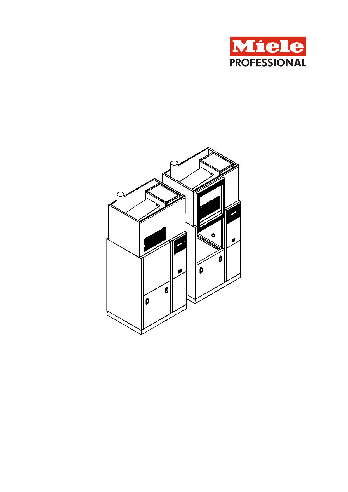
Installation plan
PG 8527 D/EL
Mat. no.
06857584
Version 05
US
Installation Plan PG 8527 D/EL
Version: 01/07/2016 Page 1
Labwasher
PG 8527
connection
(DU/S)
Voltage
3 AC 208/60 V/Hz
3 AC 208/60 V/Hz
Connected load
2.1 kW
2.1 kW
Fuse rating
3 x 15 A
3 x 15 A
Connecting cable, mi ni mum cr oss-section
4 x 12 AWG
4 x 12 AWG
(DU/E)
Voltage
3 AC 208/60 V/Hz
3 AC 208/60 V/Hz
Connected load
9.0 kW
9.0 kW
Fuse rating
3 x 30 A
3 x 30 A
Connecting cable, minimum cross-section
4 x 10 AWG
4 x 10 AWG
3. Type of heating: Steam/electric switchable
Voltage
3 AC 208/60 V/Hz
3 AC 208/60 V/Hz
Connected load
21 kW
21 kW
Fuse rating
3 x 60 A
3 x 60 A
Connecting cable, minimum cross-section
4 x 6 AWG
4 x 6 AWG
Power cord, minimum length
from upper edge of top panelling in installations
from the ceiling
13 ft.
4.0 m
above top of floor in installations from the floor
5 ft.
1.5 m
e.g. during repair or maintenance.
The plug connection must be accessible after the
installation of the machine.
Connect the device in phase with the clockwise field
of rotation.
The installations must comply with the CAT II
installation category.
Permissible maximum voltage fluctuations
Technical Data Sheet
Type of heating:
Steam/Electric
Legend:
Notes on supply connections:
Cold, hot, DI water, high pressure steam, condensate, and compressed air may be connected
from the ceiling (standard installation) or from the floor (alternative installation). A mixed
installation of these media is possible.
Electrical
2. Type of heating: Steam with electric drying unit
1. Type of heating: Steam with steam drying unit
Circled bold-type abbreviations mean:
Connection required
Abbreviations in dashed circles mean:
Connection optional or required for a specific model
EN
We recommend connecting the appliance via a plug
so that an electrical safety check can be carried out,
+/- 10%
Connection to the electrical supply must be carried
out in accordance with local and national safety
regulations.
Installation Plan PG 8527 D/EL
Version: 01/07/2016 Page 2
conductor
Equipotential bonding and grounding conductor must
Ethernet interface (for transmission)
Length of connecting cable, incl. RJ45 plug (scope of
delivery)
16.5 ft.
5.0 m
The user must install an RJ45 socket above the
machine.
Or:
Serial interface (for output on HPGL-compatible printer):
Length of connecting cable, incl. RS232 plug (scope
of delivery)
16.5 ft.
5.0 m
The user must install an RS232 socket above the
machine.
The connections/installations must be designed
according to IEC 60950.
TA OPERATION
Contact is closed during drying block
200-240/1/50-60 V/A/Hz
PRG RUNS
Contact is closed during rinsing, drying and cooling return
time.
200-240/1/50-60 V/A/Hz
OPERATION
Contact is closed while machine is switched on
200-240/1/50-60 V/A/Hz
MALFUNCTION
Contact is closed if there is a malfunction
200-240/1/50-60 V/A/Hz
PRG END
Contact is closed between program end and door
opening.
200-240/1/50-60 V/A/Hz
PAUSE M. RINSE
Contact is closed during "Pause with rinse" program
segment.
200-240/1/50-60 V/A/Hz
DRAIN STD
Contact is closed during Draining - Standard
200-240/1/50-60 V/A/Hz
DRAIN RECY.
Contact is closed during Draining - Recycling
200-240/1/50-60 V/A/Hz
User-defined
Contact is activated during water outflow, as long as
"External contact" in the block is set to "Water outflow".
200-240/1/50-60 V/A/Hz
COLD
Contact is closed during "Cold" water intake.
200-240/1/50-60 V/A/Hz
WARM
Contact is closed during "Warm" water intake.
200-240/1/50-60 V/A/Hz
AD COLD
Contact is closed during "AD Cold" water intake.
200-240/1/50-60 V/A/Hz
AD WARM
Contact is closed during "AD Warm" water intake.
200-240/1/50-60 V/A/Hz
Cold delayed
Depending on the parameter
200-240/1/50-60 V/A/Hz
Hot delayed
"switch-off delay valve", outflow will be:
200-240/1/50-60 V/A/Hz
DI-cold delayed
a. delayed (start of water inflow)
200-240/1/50-60 V/A/Hz
DI-hot delayed
b. advanced (end of water inflow)
200-240/1/50-60 V/A/Hz
DOS1-EXTERN
Activation signal for external metering pump 1
200-240/1/50-60 V/A/Hz
DOS2-EXTERN
Activation signal for external metering pump 2
200-240/1/50-60 V/A/Hz
DOS3-EXTERN
Activation signal for external metering pump 3
200-240/1/50-60 V/A/Hz
DOS4EXTERNAL
Activation signal for external metering pump 4
200-240/1/50-60 V/A/Hz
DOS5EXTERNAL
Activation signal for external metering pump 5
200-240/1/50-60 V/A/Hz
DOS6EXTERNAL
Activation signal for external metering pump 6
200-240/1/50-60 V/A/Hz
DOS7EXTERNAL
Activation signal for external metering pump 7
200-240/1/50-60 V/A/Hz
DOS8EXTERNAL
Activation signal for external metering pump 8
200-240/1/50-60 V/A/Hz
DOS9EXTERNAL
Activation signal for external metering pump 9
200-240/1/50-60 V/A/Hz
Message DOS 1
Contact is established when the corresponding pump is
activated during the program.
200-240/1/50-60 V/A/Hz
Message DOS 2
Contact is established when the corresponding pump is
activated during the program.
200-240/1/50-60 V/A/Hz
Message DOS 3
Contact is established when the corresponding pump is
activated during the program.
200-240/1/50-60 V/A/Hz
Message DOS 4
Contact is established when the corresponding pump is
activated during the program.
200-240/1/50-60 V/A/Hz
Message DOS 5
Contact is established when the corresponding pump is
200-240/1/50-60 V/A/Hz
Equipotential
bonding and
equipment
grounding
Network and
printer connection
Connection
module
Outputs
External threaded pin with washers and nut at the
machine end, size
be connected.
The following interfaces for the transmission or printing of
process data are provided at the machine:
Floating contacts (normally open contacts):
A maximum of 9 contacts may be set, possible
assignment:
M 8 M 8
Maximum contact current capacity:
activated during the program.
Installation Plan PG 8527 D/EL
Version: 01/07/2016 Page 3
SLA HZG
Peak load shut-down, steam and/or electric heater
200-240/50-60 V/Hz
DOS-EXT
Filling level of external DOS containers
200-240/50-60 V/Hz
MEDIUM
Medium dispensing activated, signal for flow and volume
control
200-240/50-60 V/Hz
EXT-TEXT
External text
200-240/50-60 V/Hz
Cold water
Temperature, max.
158°F
70°C
Max. temperature when cooling the steam condenser
with cold water
68 °F
20°C
Max. water hardness
4 gpg
4°dH
Minimum flow pressure
29 psi
200 kPa
Maximum pressure
145 psi
1,000 kPa
Volume flow
4 gal/min
15 l/min
User's connection thread according to DIN 44 991 (flat
3/4" male hose
3/4" male hose
Temperature, max.
158°F
70°C
Max. water hardness
4 gpg
4°dH
Minimum flow pressure
29 psi
200 kPa
Maximum pressure
145 psi
1,000 kPa
Volume flow
4 gal/min
15 l/min
User's connection thread according to DIN 44 991 (flat
3/4" male hose
3/4" male hose
pure water, etc.
Temperature, max.
158°F
70°C
Max. temperature when cooling the steam condenser
air)
68 °F
20°C
Max. conductivity (e.g., surgical instruments)
15 µS/cm
15 µS/cm
Minimum flow pressure
29 psi
200 kPa
Maximum pressure
145 psi
1,000 kPa
Volume flow
4 gal/min
15 l/min
User's connection thread according to DIN 44 991 (flat
3/4" male hose
3/4" male hose
(DU/E)
Steam pressure (overpressure)
36-145 psi
250-1,000 kPa
Boiling temperature
282-363°F
139-184°C
Machine variant with steam-heated drying unit (DU/S)
Optimal steam pressure (overpressure)
29-87 psi
250-600 kPa
Boiling temperature
282-329°F
139-165°C
Designed capacity
110 lb/h
50 kg/h
User-side connection thread (flat sealing)
1/2"male pipe
thread
1/2" male pipe
thread
The user must provide a trap and drain directly upstream
of the appliance's steam connection.
The steam must be provided in dry form and in TRD 611
quality.
The steam pressure directly influences the program run
Designed capacity Qn
0.07 cfm
0.12 m³/h
Supply pressure
87-174 psi
600-1,200 kPa
User-side connection thread
1/2" female pipe
1/2" female pipe
Connection
module
Inputs
Warm water
Demineralized
water
Control voltage
sealing)
sealing)
Water quality based on requirement for rinsing result.
e.g., reverse osmosis, DI water, aqua destillata, ultra-
thread
thread
thread
thread
with DI water (heat recovery of drying heat from exhaust
sealing)
Heating steam
(saturated steam
or pure steam)
Condensate User-side connection thread (flat sealing)
Machine variant with electrically heated drying unit
times. This must be taken into account when designing
and constructing the steam supply system.
thread
1/2" male pipe
thread
thread
1/2" male pipe
thread
Compressed air
Installation Plan PG 8527 D/EL
Version: 01/07/2016 Page 4
thread
thread
site, connect the SC to the cold water system.
Cooling circuit flow temperature
43°F
6°C
Max. cooling capacity
3.5 kW
3.5 kW
Maximum pressure, cooling circuit
116 psi
800 kPa
Pressure loss, steam condenser
4.3-7.2 psi
30-50 kPa
Cooling circuit volume flow
>1 gpm
>4.0 l/min
Hose nozzle, steam condenser Ø (da x l)
9/16” x 1”
14 x 25 mm
Installation of shut-off valve and filter (by the user)
To control the cooling circuit, electrically opening shut-off
user:
To connect the steam condenser, the user must suspend
Hose nozzle, steam condenser Ø (da x l)
9/16” x 1”
14 x 25 mm
Installation of shut-off valve (by the user)!
To connect the steam condenser, the user must suspend
valve (DV):
Temperature, max.
199°F
93°C
Connection
2”
50 DN
Delivery, short-time, max.
39 gal/min
150 l/min
Odor trap to be provided by user
valve (DV):
Temperature, max.
158°F
70°C
Connection
2”
50 DN
Odor trap to be provided by user
Cooling circuit
flow (optional)
Cooling circuit
return flow
(optional)
Waste water
The steam condenser (SC, option) may be connected to a
cooling circuit. If a cooling circuit is not provided at the
valves must be installed at the connection point by the
a connecting hose with an internal diameter of 9/16” (14
mm) and a length of 5 ft. (1.50 m) from the ceiling.
Required for the connection of the steam condenser to a
cooling circuit:
a connecting hose with an internal diameter of 9/16” (14
mm) and a length of 5 ft. (1.50 m) from the ceiling.
Waste water connection, required for design with drain
Tray drain
Waste water connection, required for design with drain
Installation Plan PG 8527 D/EL
Version: 01/07/2016 Page 5
Temperature, max.
199°F
93°C
Connection for drain pump, 2× each
2”
50 DN
Drain pump delivery head max.
9’ 10”
3.0 m
Delivery, short-time, max.
26 gal/min
100 l/min
Drain pump discharge hose, 2× each (di × s × l),
scope of delivery
7/8” x ¼” x 59
1/16”
22 x 6 x 1,500
mm
User hose nozzle 2x each
7/8” x 1 3/16”
22 x 30 mm
Connection for discharge hose from steam condenser
cold water supply:
2”
50 DN
Delivery head max.
9’ 10”
3.0 m
Delivery, short-time, max.
1-1.6 gal/min
4-6 l/min
Discharge hose (di × s × l)
1/2” x 1/8” x 8’ 2
1/2”
14 x 3 x 2,500
mm
User hose nozzle
1/2” x 1 3/16”
14 x 30 mm
Connection for condensate discharge hose:
2”
50 DN
Delivery head max.
9’ 10”
3.0 m
Delivery, max.
0.26 gal/min
1 l/min
Discharge hose (di × s × l)
¼” x 1/16” x 8’ 2
1/2”
6 x 2 x 2,500
mm
User hose nozzle
¼” x 3/ 4”
6 x 20 mm
Minimum diameter, discharge collecting hose
100 DN
100 DN
The use of an odour trap is recommended.
Drill hole diameter
1 7/16”
36 mm
Prior to the installation of the machine and depending on
Drain pump
(optional)
If the waste water cannot be drained through the floor, the
labwasher can be equipped with drain pumps (DP).
(optional), only if a steam condenser is connected to the
Housing bushings
for discharge
hoses, DP
machine variant
the structural conditions, openings must be provided in
the enclosure in the marked areas or at the specified
points.
Installation Plan PG 8527 D/EL
Version: 01/07/2016 Page 6
 Loading...