

Page 1
Installatietekening
Plano de instalación
Asennusohje
Plan d`installation
Plano de instalação
Installasjonsplan
Pianta di installazione
Σχέδιο εγκατάστασης
Installationsplan
Installationsplan / Installation plan
G 7824 EL AP (drain pumps)
Materialnummer / Mat.-no.: 6576291
Änderungsstand / Version: 01
Datum Zeichnung / Drawing date: 01.07.2010
Datum Legende / Legend date: 01.07.2010
Page 2

Page 3
Page 4
Page 5
Page 6

Page 7

Page 8

Page 9

Technical Datasheet
Washer-disinfector:
Heating:
Legend:
Circled, bold-type abbreviations:
Connection required
G 7824 AP
Electric (EL)
Notes on supply connections:
Cold, hot and demineralised water, high-pressure steam, condensate and compressed air
supplies can be routed through the ceiling or, alternatively, through the floor. A combination of
the two is not possible.
When installing a run of several washer-disinfectors, drain hoses can be passed through a
made-to-measure floor tray to a central drain.
Electrical
connection
Rated load
Fuse rating
Connection cable, min. cross-sectional area
Connector terminal cross-section
Connection cable, min. length
From top edge of MAV panelling if supply lines
Above finished floor if supply lines pass through
Socket must be accessible after installation.
Supply lead H05(07)RN-F with CEE socket (16 or 32
Protect supply lead against thermal exposure.
Observe correct phase sequence (clockwise).
Installationen must be in accordance with installation
Maximum permitted mains voltage variation: +/- 10%
The use of an earth leakage circuit breaker (ELCB) is
Abbreviations surrounded by broken circle:
Connection optional or required, depending on model
1. Voltage
Plug and socket connection recommended to
facilitate accessibility for electrical safety tests.
A as appropriate) to be provided on site Machine
equipped with CEE plug
category CAT II
Connection to electrical supply should be in
accordance with valid regulations and safety
standards.
strongly recommended.
Rated current: In accordance with fuse rating.
Tripping current: 30 mA.
pass through ceiling
floor
V/Hz
kW
A
mm²
mm²
m
m
3N AC 400/50
10.2
3 x 16
5 x 2.5
4
4.0
1.5
Equipotential
bond and earth
conductor
Equipotential bond and earth conductor must be
Threaded connection bolt with nut and washer fitted
on machine. Size:
connected!
M
8x1
Installationsplan G 7824 EL AP
Stand: 01.07.2010
Seite 9
Page 10

°C
°C
Country variations:
2. Voltage
Rated load
Fuse rating
Connection cable, min. cross-sectional area
V/Hz
kW
A
mm²
3 AC 230/50
10.2
3 x 30
4 x 4
Network / Printer
connection
Serial interface:
Connection cable length including RS232 plug (supplied
An RS232 connection socket above the machine must be
Connection / Installation must be carried out in accordance
output signals
TA OPERATION Contact closed during drying block
PRG RUNNING Contact closed during washing, drying and cool-down
OPERATION
FAULT
PRG END
PAUSE w.
WASH
DRAIN STD
DRAIN RECY. Contact closed during drainage (water recycling drain pump) V/A/Hz 200-240/1/50-60
COLD
HOT
DEMIN. COLD Contact closed during cold demineralised water intake
DEMIN. HOT
DOS1-EXT
DOS2-EXT
DOS3-EXT
DOS4-EXT
Connection
module
3. Voltage
Rated load
Fuse rating
Connection cable, min. cross-sectional area
The following interfaces for transferring or printing process
data are available on the machine:
as standard)
provided on site.
with IEC 60950.
Potential-free contacts (NO contacts):
A maximum of 9 contacts are available, possible assignment:
V/Hz
kW
A
AWG
m
3 AC 208/60
10.2
3 x 30
4 x 10
5.0
Max. contact load:
V/A/Hz 200-240/1/50-60
Contact closed while machine is running
Contact closed when fault occurs
Contact closed between end of programme and door opening V/A/Hz 200-240/1/50-60
Contact closed during 'Pause with wash action' stage
Contact closed during drainage
Contact closed during cold water intake
Contact closed during hot water intake
Contact closed during hot demineralised water intake
Control signal for external dispenser pump 1
Control signal for external dispenser pump 2
Control signal for external dispenser pump 3
Control signal for external dispenser pump 4
V/A/Hz 200-240/1/50-60
V/A/Hz 200-240/1/50-60
V/A/Hz 200-240/1/50-60
V/A/Hz 200-240/1/50-60
V/A/Hz 200-240/1/50-60
V/A/Hz 200-240/1/50-60
V/A/Hz 200-240/1/50-60
V/A/Hz 200-240/1/50-60
V/A/Hz 200-240/1/50-60
V/A/Hz 200-240/1/50-60
V/A/Hz 200-240/1/50-60
V/A/Hz 200-240/1/50-60
V/A/Hz 200-240/1/50-60
Module input
signals
SLA HZG
DOS-EXT
MEDIUM
Cold water
Max. water hardness
G 7824
G 7824 WES (with water softener)
Min. flow pressure
Max. pressure
Throughput
On-site connection thread according to DIN 44 991
Hot water
Max. water hardness
G 7824
G 7824 WES (with water softener)
Min. flow pressure
Max. pressure
Throughput
On-site connection thread according to DIN 44 991
Control voltage
Peak-load negotiation - Heating
Fill level of external dispenser canister
Medium dispensing active, signal for flow and volume control V/Hz
Max. temperature
Max. temperature
V/Hz
V/Hz
°dH
°dH
kPa
kPa
l/min
Inch
°dH
°dH
kPa
kPa
l/min
Inch
200-240/50-60
200-240/50-60
200-240/50-60
20
4
60
200
1000
15
3/4" external thread
(USA: 11.5 NH)
60
4
60
200
1000
15
3/4" external thread
(USA: 11.5 NH)
Installationsplan G 7824 EL AP
Stand: 01.07.2010
Seite 10
Page 11

°C
°C
DN
m
mm
mm
m
mm
mm
DN
m
mm
mm
DN
Final rinse water Water quality defined by cleaning requirements, e.g. reverse
Max. temperature
Max. conductivity (e.g. for surgical instruments)
Min. flow pressure
Max. pressure
Throughput
On-site connection thread according to DIN 44 991
osmosis, demineralised water, ultra-purified water, etc.
µS/cm 15
kPa
kPa
l/min
Inch
60
200
1000
15
3/4" external thread
(USA: 11.5 NH)
Cooling circuit
feed line
(optional)
Cooling circuit feed line temperature °C 6
Max. cooling capacity kW 3.5
Max. pressure – Cooling circuit kPa 800
Pressure loss – Steam condenser kPa 30-50
Flow rate - Cooling circuit l/min >4.0
Hose connector – Steam condenser (ext. dia. × l)
Stopcock and supply line filter to be provided on site!
Electrically operated valves to control the cooling circuit are
Valve, e.g.:
Actuating drive, e.g.:
To connect the steam condenser, a connection hose with an
Cooling circuit
return pipe
(optional)
Hose connector – Steam condenser (ext. dia. × l)
Stopcock to be provided on site!
To connect the steam condenser, a connection hose with an
Steam condenser (DK, optional) can be connected to a
cooling circuit. If an on-site cooling circuit is not available, the
steam condenser is to be connected to a cold water supply
to be provided at the on-site connections:
Heimeier thermostat valve base V-exact DT 20 (3/4"), with
pre-setting, flow coefficient 0.025 - 0.47
Heimeier Art. no.: 3512-03.000
EMOtec thermal actuating drive, 230 V 50 Hz, NC (normally
closed), Heimeier Art. no.: 1807-00.500
internal diameter of 14 mm and length 1.5 m is to be provided
on site hanging from the ceiling.
The following is required to connect the steam condenser to
the cooling circuit:
internal diameter of 14 mm and length 1.5 m is to be provided
on site hanging from the ceiling.
mm
mm
14 x 25
14 x 25
Waste water
Max. temperature
Connection for two drain pumps
Max. head height
Max. peak delivery
Drain hoses 2x (int. dia. x wall thickness x l) supplied
2 hose sleeves to be provided on site (ext. dia. x l)
Connection for steam condenser drain hose (optional), only
required if a steam condenser is connected to cold water
supply:
Max. head height
Max. delivery
Drain hose (Int. dia. × wall thickness × l)
hose sleeve to be provided on site (ext. dia. x l)
Connection for condensate drain hose:
Max. head height
Max. delivery
Drain hose (Int. dia. × wall thickness × l)
hose sleeve to be provided on site (ext. dia. x l)
Min. diameter of main drain pipe
Installation of odour trap recommended.
l/min
DN
l/min
l/min
93
50
3.0
100
22 x 6 x 1500
22 x 30
50
3.0
6
14 x 3 x 2500
14 x 30
50
3.0
1
6 x 2 x 2500
6 x 20
100
Installationsplan G 7824 EL AP
Stand: 01.07.2010
Seite 11
Page 12

mm
mm
°C
Pa
°C
Pa
°C
°C
mm
mm
mm
mm
kW
kW
kW
mm
mm
mm
mm
kg
N
mm
mm
Ports for drain
hoses
Port diameter
Holes must be drilled in the designated areas/points to suit
on-site conditions before installing the machine.
36
Vented
Air extracted from the 'unclean' side of the operation should
I. Vent to atmosphere. Vent multiple washer-disinfectors
Vent air throughput
Temperature - Mean value / peak max.
Relative humidity - Mean value / peak max.
Max. permissible pressure loss in vent duct
II. Vent to atmosphere. Vent multiple washer-disinfectors
Vent air throughput
Temperature - Mean value / peak max.
Relative humidity - Mean value / peak max.
Max. permissible pressure loss in vent duct
III. Connection without steam condenser to external fan-
Min. throughput capacity of on-site vent in washing cycle m³/h
Min. throughput capacity of on-site vent in drying cycle m³/h
Temperature - Mean value / peak max.
Relative humidity - Mean value / peak max.
IV. Connection with steam condenser to external fan-assisted
Min. throughput capacity of on-site vent in washing cycle m³/h
Min. throughput capacity of on-site vent in drying cycle m³/h
Temperature - Mean value / peak max.
Relative humidity - Mean value / peak max.
Prevent condensate backflow into washer-disinfector. Pitch
Machine-side connection (ext. dia. × wall thickness)
be replenished by ensuring sufficient air intake.
individually (do not use manifold):
individually (do not use manifold):
assisted vent:
vent:
vent ducting and discharge condensate at lowest point.
m³/h
% 80/100
m³/h
% <70/100
% 80/100
% <70/100
100 x 1.25
125
70/95
350
125
28/32
150
50
150
70/95
50
150
28/32
Machine feet
Floor bolts
Heat dissipation
to room
Clean side
Machine data
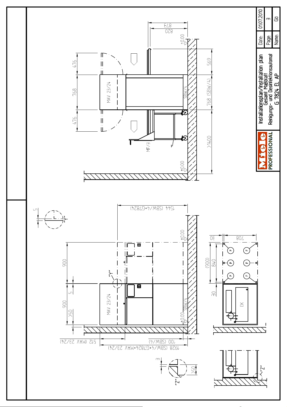
Height incl. floor tray and top-box panelling
Width
Depth
Net weight
Dynamic floor load
Knocked down width incl. pallet
Knocked down height incl. pallet
Installation should only be carried out by authorised fitters in accordance with valid regulations!
Observe installation instructions when installing machine! All rights reserved! Dimensions in mm
Height-adjustable
Foot diameter
Parts supplied with floor tray:
Adhesive anchors (4 off)
Hole diameter
Unclean side
Load on removal
Height incl. floor tray and lid
10
25
M 8 x 150
8
0.5
0.5
0.5
1544
1928
900
768
370
~4910
1020
1600
Installationsplan G 7824 EL AP
Stand: 01.07.2010
Seite 12
Page 13

Notes on supply connections:
Cold, hot and demineralised water can be routed through the ceiling or, alternatively, through the floor.
A combination of the two is not possible. Cooling circuit feed and return pipes for steam condenser
(optional) through ceiling only. Easily accessible central stopcock and main switch recommended.
Waste water connection:
The on-site drain pipe serving the machine drain hose should be located at the side of the machine.
Service ports in the machine casing can be made on site for connection to on-site utilities. Drain hoses
are of a sufficient length to extend to the ports and should be extended outside the machine casing.
Ports should be 36 mm in diameter. Two grommets, Mat. no. 2723340, required to provide antiscuffing hose protection.
Two blind stoppers, Mat. no. 27119630, are required to provide anti-scuffing protection for condensate
and steam condenser hoses. Blind stoppers should be cut open on site.
When installing a run of several washer-disinfectors, drain hoses can be passed through a made-tomeasure floor tray to a central drain. Connection to a common drain pipe above the machines is also
possible. This option requires the use of a strain-relief bush for the drain hoses. If a steam condenser
is supplied from a potable water supply, the machine should be connected to the drainage system
using the non-return device provided. The max. head height of the pumps should should be taken into
consideration!
All drain hoses from washer-disinfectors should be connected to the on-site drain pipe using pressuretight connections.
Electrical connection:
Electrical supply lines can be routed through floor or ceiling. Min. cable length of 1500 mm above
finished floor surface required with access through floor. Min. cable length of 4000 mm from top edge
of top-box panelling required with access through ceiling.
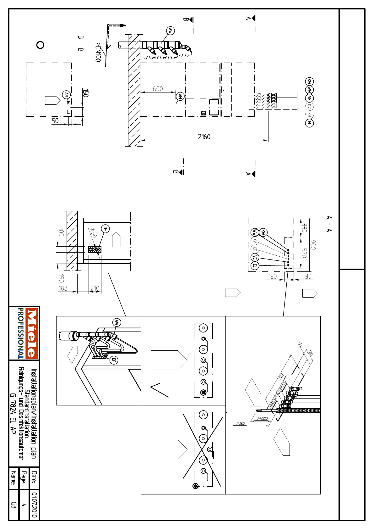
Standard installation, chemical supply connections:
Install supply lines vertically from ceiling, adjust and locate. All pipework, including insulation, fittings
and valves with taps should be located within the designated area (520 mm × 130 mm). No part of the
installation should extend beyond this area.
Hot, cold and demineralised water lines end with a ¾" threaded union 2,160 mm above finished floor.
If the machine is fitted with a steam condenser, install the cooling circuit feed and return pipes vertically
from the ceiling, and adjust and secure them as necessary. The cooling circuit feed and return pipes
end in the machine installation area with hose sleeves at a height of 2,160 mm above finished floor
(OKFF). Both are connected to the steam condenser with a flexible hose (int. diameter 14 mm) which
is to be provided on site. In the absence of cooling circuit, connect steam condenser to cold water.
Easily accessible central stopcock and main switch recommended.
Installationsplan G 7824 EL AP
Stand: 01.07.2010
Seite 13
Page 14

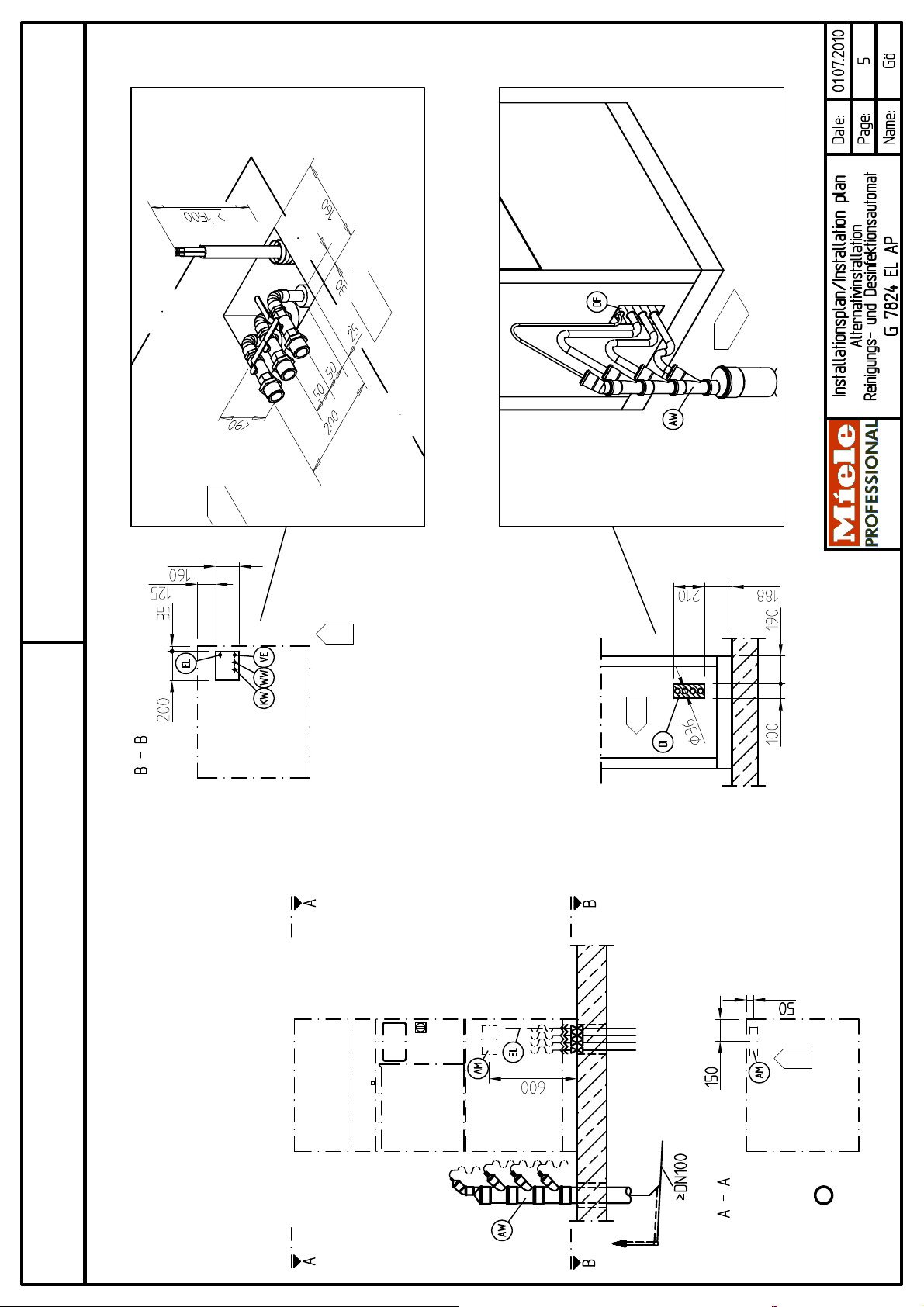
Alternative installation, chemical supply connections:
Route supply lines through floor to approx. 200 mm above finished floor and secure. Supply lines are
shortened after installation of plinth/floor tray. If plinth/floor tray is planned later, use pipe caps to close
pipes.
Install floor tray horizontally using spirit level. Stopcocks in the chemical supply lines are installed after
the floor tray has been fitted. Pipework and stopcocks should rise by no more than 90 mm above
finished floor and should on no account rise above plinth/floor tray.
If the machine is fitted with a steam condenser, install the cooling circuit feed and return pipes vertically
from the ceiling, and adjust and secure them as necessary. The cooling circuit feed and return pipes
end in the machine installation area with hose sleeves at a height of 2,160 mm above finished floor
(OKFF). Both are connected to the steam condenser with a flexible hose (int. diameter 14 mm) which
is to be provided on site. In the absence of cooling circuit, connect steam condenser to cold water.
Easily accessible central stopcock and main switch recommended.
On-site front panelling:
In the case of two-door (barrier) machines (G7824), a removable and lockable panel must be provided
on site for installation above the door at the same height as the MAV panelling (512 mm). The lid, Mat.
no. 5968080, is fitted above this panel.
Standard installation:
A cover with water-tight pass-through cut-outs for supplies must be provided above the machine to
prevent water ingress into the washer-disinfector in the event of leakage from stopcocks or hose
connectors.
Waste air installation:
In order to expel vapours, air throughput of 150 m³/h for each machine is required on the unclean side
of the operation.
Connection to external vent system with or without steam condenser:
Connection of the washer-disinfector to an external vent system is via an extractor canopy. An air gap
of at least 80 mm should be provided. A suitable vent canopy is provided with the washer-disinfector.
The use of a two-stage fan is recommended (cf. Technical Data Sheet 'Electrical connection' on fan
control). Laying a flexible duct to directly above the machine facilitates installation.
Venting to atmosphere:
The canopy provided should not be fitted if the washer-disinfector is vented directly to atmosphere.
Never merge vent ducts from multiple washer-disinfectors! Vent each machine separately!
Installationsplan G 7824 EL AP
Stand: 01.07.2010
Seite 14
 Loading...