

Page 1

Operating Instructions
Laboratory Glassware
Washer
G 7804
To prevent accidents
and machine damage
read these instructions
before
installation or use.
UV
M.-Nr. 05 893 780
Page 2

Contents
IMPORTANT SAFETY INSTRUCTIONS. . . . . . . . . . . . . . . . . . . . . . . . . . . . . . . . . 3
Description of the Machine . . . . . . . . . . . . . . . . . . . . . . . . . . . . . . . . . . . . . . . . . . 7
Guide to the glassware washer . . . . . . . . . . . . . . . . . . . . . . . . . . . . . . . . . . . . . . 8
Opening and closing the door . . . . . . . . . . . . . . . . . . . . . . . . . . . . . . . . . . . . . . 10
Water softener . . . . . . . . . . . . . . . . . . . . . . . . . . . . . . . . . . . . . . . . . . . . . . . . . . . 12
Setting the water softener . . . . . . . . . . . . . . . . . . . . . . . . . . . . . . . . . . . . . . . . . . . 14
Filling the salt reservoir . . . . . . . . . . . . . . . . . . . . . . . . . . . . . . . . . . . . . . . . . . . . . 15
Salt indicator . . . . . . . . . . . . . . . . . . . . . . . . . . . . . . . . . . . . . . . . . . . . . . . . . . . . . 16
Loading . . . . . . . . . . . . . . . . . . . . . . . . . . . . . . . . . . . . . . . . . . . . . . . . . . . . . . . . . 17
Adjusting the upper basket . . . . . . . . . . . . . . . . . . . . . . . . . . . . . . . . . . . . . . . . . . 21
Adding detergent . . . . . . . . . . . . . . . . . . . . . . . . . . . . . . . . . . . . . . . . . . . . . . . . . 22
Adding neutralizer . . . . . . . . . . . . . . . . . . . . . . . . . . . . . . . . . . . . . . . . . . . . . . . . 23
Operation . . . . . . . . . . . . . . . . . . . . . . . . . . . . . . . . . . . . . . . . . . . . . . . . . . . . . . . 25
Turning on the lab washer . . . . . . . . . . . . . . . . . . . . . . . . . . . . . . . . . . . . . . . . . . . 25
Starting a program. . . . . . . . . . . . . . . . . . . . . . . . . . . . . . . . . . . . . . . . . . . . . . . . . 25
Drying . . . . . . . . . . . . . . . . . . . . . . . . . . . . . . . . . . . . . . . . . . . . . . . . . . . . . . . . . . 25
Changing a program . . . . . . . . . . . . . . . . . . . . . . . . . . . . . . . . . . . . . . . . . . . . . . . 26
Program sequence display . . . . . . . . . . . . . . . . . . . . . . . . . . . . . . . . . . . . . . . . . . 26
At the end of a program. . . . . . . . . . . . . . . . . . . . . . . . . . . . . . . . . . . . . . . . . . . . . 26
Turning off . . . . . . . . . . . . . . . . . . . . . . . . . . . . . . . . . . . . . . . . . . . . . . . . . . . . . . . 26
Canceling a program. . . . . . . . . . . . . . . . . . . . . . . . . . . . . . . . . . . . . . . . . . . . . . . 26
Program guide . . . . . . . . . . . . . . . . . . . . . . . . . . . . . . . . . . . . . . . . . . . . . . . . . . . 27
Programming special functions . . . . . . . . . . . . . . . . . . . . . . . . . . . . . . . . . . . . . 28
Machine care . . . . . . . . . . . . . . . . . . . . . . . . . . . . . . . . . . . . . . . . . . . . . . . . . . . . 32
Frequently asked questions . . . . . . . . . . . . . . . . . . . . . . . . . . . . . . . . . . . . . . . . 35
After Sales Service . . . . . . . . . . . . . . . . . . . . . . . . . . . . . . . . . . . . . . . . . . . . . . . 38
Caring for the environment . . . . . . . . . . . . . . . . . . . . . . . . . . . . . . . . . . . . . . . . . 40
Installation . . . . . . . . . . . . . . . . . . . . . . . . . . . . . . . . . . . . . . . . . . . . . . . . . . . . . . 41
Plumbing. . . . . . . . . . . . . . . . . . . . . . . . . . . . . . . . . . . . . . . . . . . . . . . . . . . . . . . . 43
Water inlet . . . . . . . . . . . . . . . . . . . . . . . . . . . . . . . . . . . . . . . . . . . . . . . . . . . . . . . 43
Electrical connection. . . . . . . . . . . . . . . . . . . . . . . . . . . . . . . . . . . . . . . . . . . . . . 46
Technical data . . . . . . . . . . . . . . . . . . . . . . . . . . . . . . . . . . . . . . . . . . . . . . . . . . . 48
2
Page 3
IMPORTANT SAFETY INSTRUCTIONS
This appliance is only intended for
specialized applications. Only use
the appliance for its intended
purpose. Any other use, conversion
or modification is dangerous. The
manufacturer cannot be held
responsible for damages caused by
improper use of this machine.
This equipment is not designed for
maritime use or for use in mobile
installations, such as caravans or
aircraft. However, under certain
conditions it may be possible for an
installation in these applications. Please
contact the nearest Miele dealer or the
Miele Technical Service Department
with specific requirements.
This appliance complies with current
safety requirements. Improper use of
the appliance can lead to personal
injury and material damage.
Read all instructions before installing
or using this appliance.
Keep these operating instructions in
a safe place and pass them on to
any future user.
Installation and Service
The machine should only be
installed, maintained and repaired
by a Miele authorized service
technician. Repairs by unqualified
persons could be dangerous.
Do not install the machine in an
area where a danger of explosion
or of freezing may be present.
Be certain this appliance is
properly installed and grounded by
an authorized technician. To guarantee
the electrical safety of this appliance,
continuity must exist between the
appliance and an effective grounding
system. It is imperative that this basic
safety requirement be met. If there is
any doubt, have the electrical system of
the house checked by a qualified
technician. The manufacturer cannot be
held responsible for damage or injury
caused by the lack of or inadequacy of
an effective grounding system .
A damaged machine is dangerous.
Turn off the machine at the main
power supply immediately and call the
Miele Technical Service Department.
Before servicing, disconnect the
power supply by either removing
the fuse or "tripping" the circuit breaker.
3
Page 4

IMPORTANT SAFETY INSTRUCTIONS
Use
Personnel operating the machine
should be trained regularly.
Children and untrained personnel must
not be allowed access to the machine
or its controls.
BURN AND SCALD HAZARD
This washer reaches very high
temperatures. Take care when
unloading the unit. Let baskets and
inserts cool before touching them. Any
water which may remain in containers
will be very hot and must be emptied
into the wash cabinet.
BURN HAZARD
The heating elements become
extremely hot during use. Do not touch
the heating elements during or directly
after the end of a program.
Take care when handling liquids
such as detergents, wetting agents
or neutralizing agents. These may
contain irritant or corrosive ingredients.
Do not use an organic solvent in this
washer, as an explosion may occur.
Wear protective gloves and goggles.
The manufacturer’s safety conditions
must be observed for all chemical
agents.
Be careful when sorting items with
sharp pointed ends. If possible,
place the pointed end downwards.
The water in the machine must not
be used as drinking water.
Do not sit or lean on the open door.
Injury or machine damage could
result.
Never clean the machine or its
vicinity with a water hose or a high
pressure hose.
Avoid inhaling powdered
detergent. If swallowed, they can
cause burning in the mouth and throat,
or inhibit breathing.
4
Page 5

IMPORTANT SAFETY INSTRUCTIONS
Only use cleaning agents
formulated for special processes
and approved by Miele for use with this
machine. Use of unsuitable cleaning
agents could adversely affect the
components of the machine.
Pre-treatments with detergents can
create suds, as can certain rinsing
agents. For pre-treatment and / or
cleaning only, use low-sudsing
detergents which have been approved
by Miele. Suds can have an adverse
effect on the cleaning process.
Where a chemical additive is
recommended on technical
application grounds (for example, with
a cleaning agent), this does not imply
that the manufacturer of the machine
takes responsibility for the effect of the
chemical on the material of the items
being cleaned. Please be aware that
changes in formulation, storage
conditions, etc, which may not be
published by the chemical producer,
can have a negative effect on the
cleaning result.
When using cleaning agents and
specialized products, it is essential
that the manufacturer’s instructions are
followed. Only use the product for the
application described by the
manufacturer to avoid any material
damage or the occurrence of strong
chemical reactions.
The machine is designed only for
operation with water and additive
cleaning agents. Organic solvents must
not be used in the machine. An
explosion or machine corrosion could
occur with the use of organic solvents.
In critical applications where very
high requirements must be met, it
is strongly recommended that all the
relevant factors for the process, such
as cleaning agent, quality of water, etc,.
are discussed with the Miele Technical
Service Department.
5
Page 6

IMPORTANT SAFETY INSTRUCTIONS
If the cleaning result is subject to
particularly stringent requirements
(e.g. chemical analysis, specialized
processes), a regular quality control
test should be carried out by the user to
ensure that the required standards are
being achieved.
The mobile units and special
inserts should only be used for
their specific application.
Empty any containers or utensils
before arranging them in the
machine.
Do not allow any remains of acids
or solvents, particularly
hydrochloric acid or chloride solutions,
to get into the wash cabinet. The
presence of any solvents should be
minimized (especially those in hazard
class A1).
To prevent corrosion damage,
ensure that solutions or steam
containing hydrochloric acid do not
come into contact with the steel outer
casing of the machine.
Accessories
Only genuine Miele parts or
accessories should be used with
the G 7804 Laboratory Glassware
washer. The performance and safety of
non-genuine parts or accessories
cannot be guaranteed, and use of such
parts or items may void the machine
warranty. If you have specific questions
about machine options or accessories,
please call Miele.
Disposal of an appliance
When discarding an old laboratory
washer, disconnect it from the
power supply, remove the door to the
wash cabinet and cut off the power
cord.
For environmental and safety
reasons, ensure the machine is
completely drained of any residual
water and cleaning agent. (Observe
safety regulations and wear safety
goggles and gloves). Make appropriate
arrangements for the safe disposal of
the machine.
SAVE THESE
INSTRUCTIONS
6
Page 7

The Miele G 7804 represents the
highest-quality general purpose
laboratory glassware washer on the
market today. Equipped with three
wash routines, the G 7804 can handle a
wide variety of cleaning challenges
found in basic laboratory environments.
The G 7804 can accommodate a
variety of baskets and inserts
specifically designed for laboratory
glassware. This includes injection
baskets for difficult to clean narrow
necked items, specially designed
pipette cleaning baskets and standard
baskets for wide-mouthed items.
Description of the Machine
7
Page 8
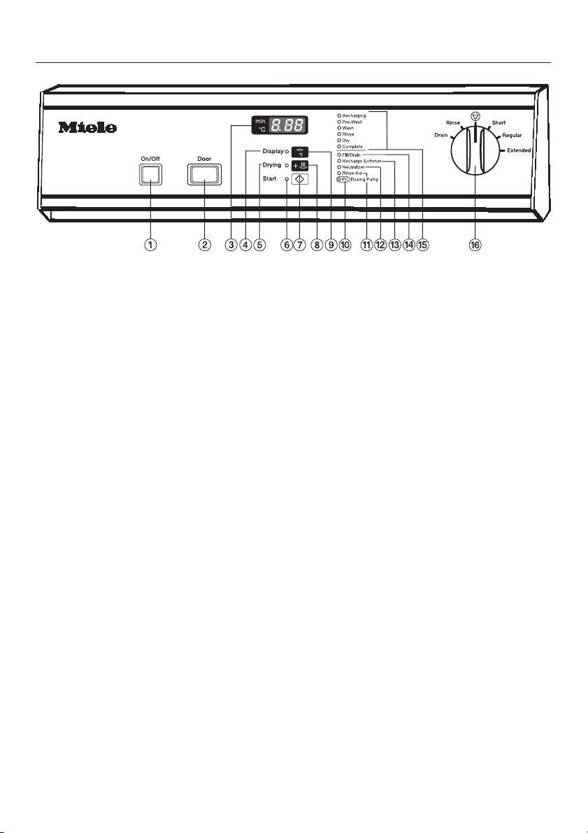
Guide to the glassware washer
a "On/Off" button
b "Door" button
c Display
d "Display" indicator
e "Drying" indicator
f "Start" indicator
g "Start" button
h "Drying" button
i Button to display "Actual time" or
"Elapsed wash time"
j "Add Detergent" indicator
k "Add Rinse Aid" indicator
l "Add Neutralizer" indicator
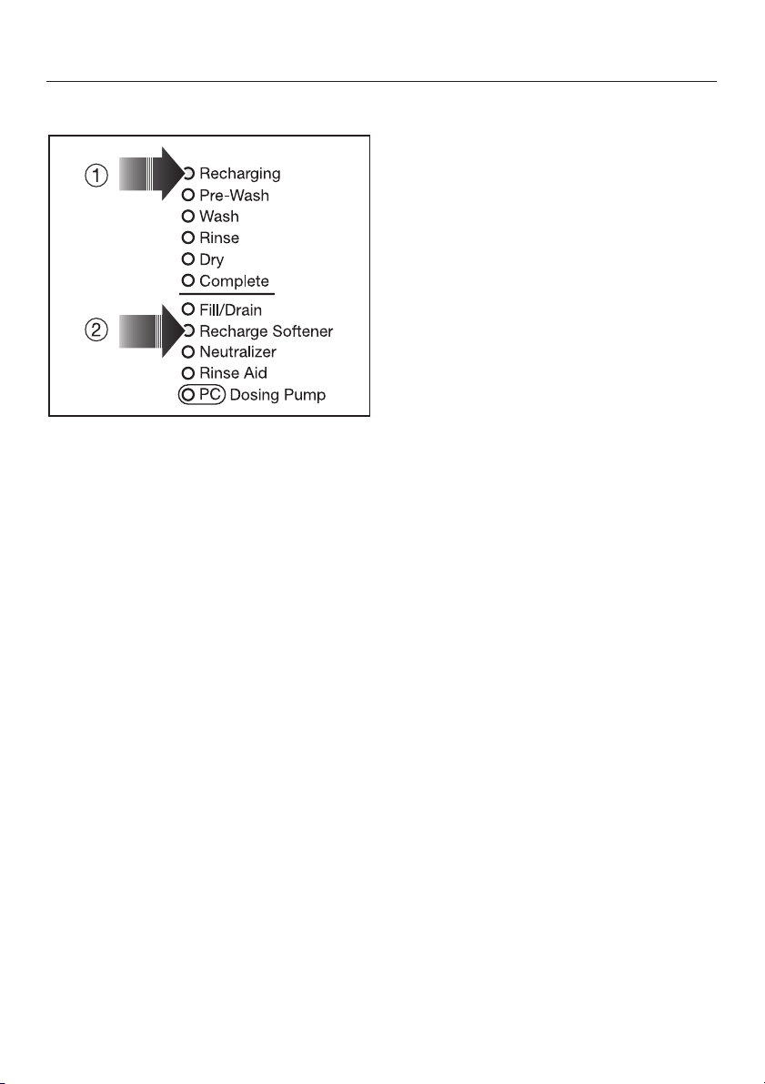
m "Recharge Softener" indicator
n "Fill/Drain" indicator
o Program sequence indicators
p Program selector
8
Page 9
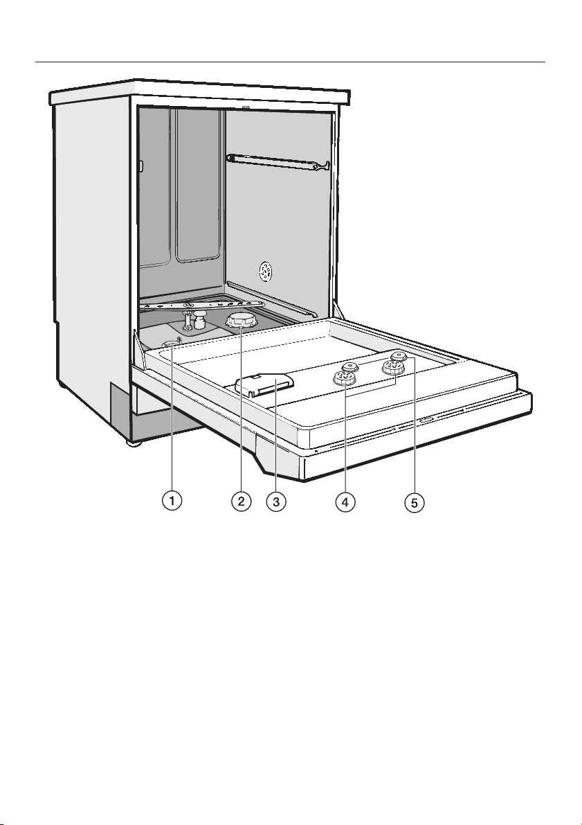
Guide to the glassware washer
a Filter combination
b Salt reservoir
(water softener)
c Dispenser for powdered detergent
d Reservoir for neutralizer
(with dosage selector)
e Level indicators
9
Page 10

Opening and closing the door
Electric door lock
The machine is equipped with an
electric door lock. The door can only be
opened when the electrical supply to
the machine is turned on, and the
"On/Off" button is pressed.
To open the door
Press the "Door" button in as far as it
^
will go. At the same time, grip the
handle and open the door.
After the first intake of water, the door
remains locked and cannot be opened
until the end of the program (except
during the "Rinse" and "Drain"
programs). The machine can be
programmed to open during the
"Drying" program, if desired.
Do not touch the heating elements.
They remain hot for some time after
the end of the program and can
cause burns.
To cancel a program
If a program has to be canceled in an
emergency, e.g. the program has been
interrupted due to a fault, the door will
have to be opened manually.
Turn the program selector to the
^
"Stop" f position. The program is
canceled after approximately
2 seconds.
To close the door
^
Lift the door upwards and push it
until it clicks shut. Do not press the
release catch while shutting the door.
10
Page 11
To open the door with the
emergency release
The emergency release should only be
used when the door cannot be opened
normally, e.g. in the event of a power
failure.
Turn the program selector to "Stop"
^
f.
Press the "On/Off" button to turn the
^
machine off.
Take precaution against pressure
^
wave release (rapid opening of the
door).
Opening and closing the door
^ Pull the emergency release cable
(located at the bottom of the machine
behind the service panel) downwards
to open the door.
The door latch will reset after the
emergency cable has been activated.
11
Page 12

Water softener
To avoid the build-up of calcium
deposits on glassware and the
machine, the water may need to be
softened (where the supply hardness
exceeds 107 ppm CaCO
).
3
To ensure a steady supply of soft water,
the water softener must always be:
1. correctly set (programmed) and
2. regenerated with salt as soon as the
"Recharge Softener" indicator
illuminates.
The water softener should be set to
correspond with the water hardness
upon installation of the machine.
Your local water authority can advise
you on the water hardness in your area.
Setting the water softener
The machine is set at the factory for a
water hardness setting of 19*,
corresponding to 339 ppm CaCO
your water supply is harder or softer
than this, the setting of the controls
should be changed.
Where the water hardness fluctuates
e.g. between 160 - 310 ppm, always
program the machine to the higher
value, 310 ppm in this example.
. If
3
12
Page 13
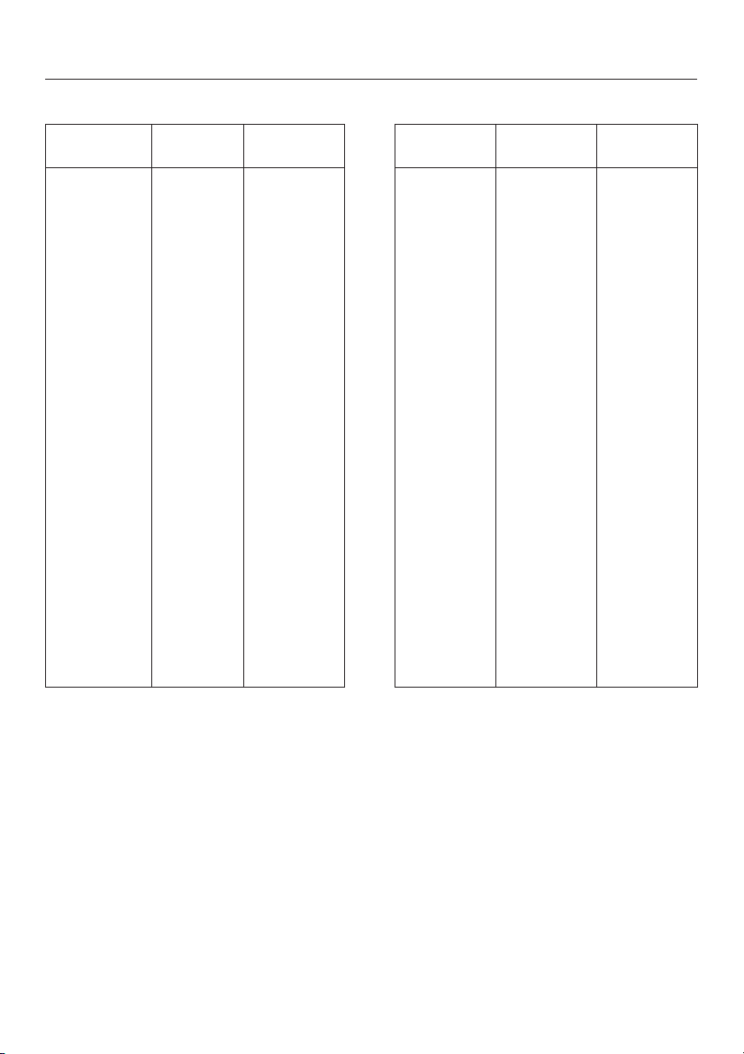
Settings
Water softener
Settings
1 - 30
1
2
3
4
5
6
7
8
9
10
11
12
13
14
15
16
17
18
19
20
21
22
23
24
25
26
27
28
29
30
gr/gal
1 - 30
1
2
3
4
5
6
7
8
9
10
11
12
13
14
15
16
17
18
19 *)
20
21
22
23
24
25
26
27
28
29
30
ppm
CaCO
20
40
50
70
90
110
130
140
160
180
200
220
230
250
270
290
310
320
340
360
380
400
410
430
450
470
490
500
520
540
Settings
3
31 - 60
31
32
33
34
35
36
37
38
39
40
41
42
43
44
45
46
47
48
49
50
51
52
53
54
55
56
57
58
59
60
gr/gal
31 - 60
31
32
33
34
35
36
37
38
39
40
41
42
43
44
45
46
47
48
49
50
51
52
53
54
55
56
57
58
59
60
ppm
CaCO
560
580
590
610
630
650
670
680
700
720
740
760
770
790
810
830
850
860
880
900
920
940
950
970
990
1010
1030
1040
1060
1080
3
*) factory setting
13
Page 14

Water softener
Setting the water softener
Turn the machine off.
^
Turn the program selector to "Stop"
^
f.
Press and hold the "Display" and
^
"Start" buttons. At the same time,
turn the machine on with the "On/Off"
button. The display shows the current
program status "P...".
The "Fill/Drain" indicator will
illuminate.
Press the "Drying" button once. "E01"
^
appears in the display.
^ Turn the program selector to the
1-o’clock position.
The display shows "19". (Factory
setting of the water softener in
gr/gal).
^ Press and hold the "Display" button
until the desired setting water
hardness (in gr/gal) shows up in the
display.
The counter starts with "0" after
reaching "60".
If there is a fault, it will be helpful to
know the water hardness of the local
water supply.
Enter the local water hardness level
^
here:
If your water is already soft and you
^
would like to deactivate the water
softener, set the hardness setting to
"0".
^
Press the "Start" button. "SP" appears
in the display.
^
Press the "Start" button again. The
setting will be stored and the display
field clears.
14
Page 15
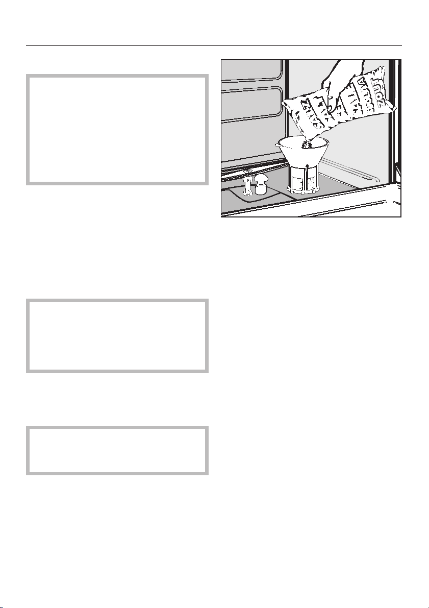
Filling the salt reservoir
Only special, coarse-grained
reactivation salt* should be used in
this machine.
*Available from Miele’s Professional
Customer Service Department.
Please see back page for more
information.
Do not use other types of salt, e.g. table
salt, agricultural or gritting salt. These
could contain components which are
insoluble in water and could damage
the water softener. If in doubt, consult
Miele’s Professional Department.
The salt reservoir holds approx. 2.5 kg
of salt.
,
Inadvertently filling the salt
reservoir with detergent will damage
the water softener.
Before filling, make sure that you are
using reactivation salt.
Water softener
Place the funnel provided in place.
^
^ Carefully fill the reservoir with salt.
Displaced water will run out as it is
being filled.
^ Wipe any residual salt off the screw
threads on the socket.
^ Screw the cap on firmly.
^ Immediately after this step: Run the
"Rinse" program to remove any traces
of salt from the cabinet.
^
Remove the bottom basket from the
machine.
^
Unscrew the salt reservoir cap.
Before filling the salt reservoir with
reactivation salt for the first time fill it
with approx. 2.5 liters of water.
Note: There may be a delay before the
"Rinse" program starts due to the
reactivation of the water softener.
15
Page 16
Water softener
Salt indicator
When the salt reservoir is empty the
"Recharge Softener" indicator, b,
illuminates to remind you to fill the
reservoir.
Reactivation takes place automatically
during a program. The "Recharging"
indicator, a, illuminates while this is
occurring.
16
Page 17

Loading
The following instructions relate only to
basic preparation and loading of
glassware. There are additional
requirements for particular applications.
Loading the machine
Remove debris
Empty all glassware before loading
^
into the machine.
Ensure that no acid or solvent
residues, especially hydrochloric
acid or chlorides, get into the wash
cabinet.
^ Remove all agar residue from petri
dishes.
^ Remove blood clots and residue from
test tubes, etc.
^ Remove all stoppers, corks, labels,
sealing wax residue, etc.
Note
Load items so that water will cover all
^
surfaces. This ensures that they will
be properly cleaned.
Do not place items to be cleaned
^
inside of other pieces, where they
may be concealed.
Hollow vessels, such as beakers,
^
graduated cylinders, flasks, etc.,
should be inverted and placed in the
correct inserts to ensure proper
cleaning. A cover net can be used to
reduce the risk of glass breakage
during the wash process.
^ Petri dishes and similar items should
be placed in the correct insert with
the soiled side facing center.
^ Pipettes should be placed with the
narrow end pointing down.
^ Deep-based items should be placed
at an angle to allow water to run off
easily.
^
Tall, narrow pieces should be placed
in the center of the basket for best
water coverage.
^
The spray arms must not be blocked
by items that are too tall or hang
through baskets. Check clearance by
manually rotating the spray arms.
17
Page 18

Loading
Important:
Make sure that the spring adapter for
the water connection engages correctly
when a basket or injector unit is
inserted into the machine. It must be
4 - 5 mm higher than the water
connection inlet in the machine. If this is
not the case, adjust the adapter by
performing the following steps:
Loosen the locking ring.
^
Push up the adapter 4 - 5 mm and
^
tighten the locking ring.
Select baskets and inserts which are
appropriate for the application.
Please contact Miele’s application
specialist for advice:
1-800-991-9380
18
Page 19

Loading examples
Loading
O 188 Upper basket
For various inserts.
E 350
Injector wagon
For narrow necked glassware,
15 injectors, 160 mm high;
18 injectors, 220 mm high.
O 187
Injector wagon
(Upper basket) For direct injection of
narrow necked glassware,
34 injectors,160 mm high.
19
Page 20

Loading
U 874 Lower basket
For various inserts.
E 109
Stainless steel half insert to
accommodate 21 beakers up to 250 ml,
Erlenmeyer flasks, round flasks etc.
E 106
Stainless steel half insert with 28 spring
hooks in 2 different heights for various
glassware, e.g. narrow necked flasks,
graduated cylinders, medicine bottles,
etc.
20
Page 21

Adjusting the upper basket
The upper basket can be adjusted
above and below the middle position
by 2 cm.
Example:
Upper basket O 188/1 and lower
basket U 874
(measurements do not include inserts)
Loading
Upper
basket
position
Upper
Middle
Lower
Upper basket
height
cm inches cm inches
15.5 61/8" 28.5 111/4"
17.5 67/8" 26.5 107/16"
19.5 711/16" 24.5 95/8"
Lower basket
height
To adjust the upper basket:
^ Pull out the upper basket, lift from the
runners and remove.
^ Unscrew the roller bearings on both
sides of the basket with a wrench
and reposition as required.
21
Page 22

Adding detergent
Only use cleaning agents
formulated for this machine. Do not
use detergents formulated for
domestic dishwashers.
Powdered detergent must be placed in
the detergent container prior to every
program (except for "Rinse" and
"Drain".)
Add detergent to the compartment.
^
Dosage: approx. 3 g/l (equivalent to
30 g per cleaning sequence).
Follow manufacturer’s instructions if
they differ.
^ Close the dispenser lid.
^ Press the opening catch on the
container (see arrow) forwards. The
flap will spring open. (The flap is
always open at the end of a
program).
22
Page 23

Adding neutralizer
The Dual Dosing container for liquid
agents incorporated in the door has a
capacity of 2 x 180 ml.
Inadvertently filling the storage
,
reservoir with detergent will damage
the reservoir.
Neutralizer
(factory setting)
To reduce the pH to neutral after the
alkaline cleaning, neutralizing agent
needs to be used.
Adding neutralizer
When using the machine for the first
time or when the "Add neutralizer"
indicator lights, add neutralizer to the
storage containers.
The storage containers have an
additional level indicator at the inner
side of the door.
^ Open the door fully.
^
Unscrew the caps. Wear protective
gloves.
23
Page 24

Adding neutralizer
Pour neutralizing agent into the
^
reservoir until the level indicator is
dark (see arrow on illustration). Use a
funnel if necessary.
^ Replace and tighten the cap. Clean
up any spilled neutralizer.
^ Wait until the "Add neutralizer"
indicator illuminates again before
refilling.
Setting the dosage
The dosage adjuster in the opening has
settings adjustable from 1 to 6 (1- 6 ml).
It is preset to "5" (10 ml) as the
recommended dosage for neutralizer.
^ Use a flat headed screw driver to turn
the dial to the correct setting.
24
Page 25

Operation
Turning on the lab washer
Make sure the spray arms are not
^
blocked.
Close the door.
^
^ Press the "On/Off" button to turn the
machine on.
Starting a program
^ Turn the program selector clockwise
or counterclockwise to the desired
program. Refer to the Program Guide
for more details.
The wash temperature of the selected
program is shown in the display
(except for "Rinse" and "Drain").
The "Start" indicator will flash.
^
Select the "Drying" button, if
necessary.
^
Press the "Start" button. The actual
temperature is displayed.
The "Start" indicator will illuminate.
Drying
"Drying" may be selected as an
additional feature once a program has
been selected (except in the "Rinse"
and "Drain" programs). Drying is
phased over 10 minutes. The total
running time of the program lengthens
accordingly.
Once the program has started, all other
programs are blocked. If the program
selector is turned to another program
during the running program, the values
shown in the display disappear. The
values appear again if the program
selector is turned back to the running
program.
^
Press the "Display" button to alternate
between elapsed time and actual
time in the display during the
program.
25
Page 26

Operation
Changing a program
If the selected program has not yet
been started:
Turn the program selector to the new
^
program.
Select the "Drying" feature, if
^
necessary.
Press the "Start" button.
^
Program sequence display
The current step of a wash program is
indicated by a program sequence
display.
At the end of a program
When the "Complete" indicator
illuminates, the "Start" indicator goes
out and the display shows a "0", the
program has ended. A buzzer will
sound for 30 seconds. (The buzzer
function can be changed; see
"Programming special functions.")
Turning off
Canceling a program
Once a program is running, it should
only be canceled in extreme cases,
e.g. when glassware is knocking
against each other and has to be
rearranged.
Turn the program selector to "Stop".
^
The program is canceled after
2 seconds.
Open the door with the "Door" button.
^
Caution! Water and items in the
machine may be hot. Danger of
burning or scalding.
^ Rearrange or remove the items (wear
protective gloves where necessary.)
^ Replenish powdered detergent if
necessary.
^ Close the door.
^ Select the "Drain" program to allow
the waste water to drain.
^
Select and start the program.
^
Press in and release the "On/Off"
button to turn the machine off.
26
Page 27

Program Program cycle
Program guide
Pre-
wash
A
SHORT
Main wash Interim
rinse 1
X
70°C/5’
Interim
rinse 2
(X)
DOS 3
Final rinse Drying
70°C/3’
(DI)
B
REGULAR
C
EXTENDED
XX
X
70°C/5’XDOS 3
70°C/5’XDOS 3
(X)
(DI)
(X)
(DI)
70°C/3’
70°C/3’
6
DRAIN
D
X
RINSE
X = Sections included in a program (with temperature/temperature holding time)
A second interim rinse can be activated (see "Programming special functions").
DOS 3 = Neutralizer dosage
DI (Aqua destillata) = distilled water
X
DI
X
DI
X
DI
(Optional
function)
(X)
(X)
(X)
27
Page 28

Programming special functions
Note
Unoccupied program selector
–
positions are displayed by a bar (-)
in the middle display element.
The programming level can be
–
scanned if the selector is in the
"Stop" f position.
1. Selecting a second interim
rinse
A second interim rinse can be
programmed to improve interim rinsing
in all programs (except "Rinse").
Turn the program selector to "STOP"
^
f.
Turn the machine off.
^
Press and hold "Display" and "Start".
^
At the same time, turn the machine
on with the "On/Off" button..
The displays shows the current
program status "P...".
The "Fill/Drain" indicator lights.
^ Press the "Drying" button once. "E01"
appears in the display.
^ Turn the program selector to the
5-o’clock position.
The display shows either "50" or "51".
"50" = without Interim rinse II.
"51" = with Interim rinse II.
28
^ Press "Drying" to change from "50" to
"51" or vice versa.
^
Press the "Start" button. "SP" appears
in the display.
^
Press the "Start" button again. The
change has been saved.
^
Please note the changed setting:
Page 29

Programming special functions
2. Activating Delay Start and
setting the Delay Start time
The start of a wash program can be
delayed up to 24 hours in 30 minute
increments.
Note:
The Delay Start should only be selected
in programs "Regular" and "Extended".
The "Short" program, cannot provide a
good cleaning result when Delay Start
is selected. The washing temperatures
and time is not sufficient to clean
dried-on items.
a) Activating Delay Start
^ Turn the program selector to "Stop"
f.
^ Turn the machine off.
^ Press and hold "Display" and "Start".
At the same time, turn the machine
on with the "On/Off" button.
The display shows the current
program status "P...".
The "Fill/Drain" indicator will
illuminate.
Press "Display" to change from "80" to
^
"81", or vice versa.
Press the "Start" button. "SP" appears
^
in the display.
Press the "Start" button again. The
^
change has been saved.
Please note the changed setting:
^
b) Setting the Delay Start period
The Delay Start period (from 30 minutes
to 24 hours) must be set before a
program is started.
^ After selecting a program, (see
"Starting a program"), press the
"Display" button or hold it in until the
required value is displayed. The
"Display" indicator illuminates.
After the "Start" button is pressed, the
Delay Start period will count down in
the display until the program
automatically starts.
^
Press the "Drying" button once. "E01"
appears in the display.
^
Turn the program selector clockwise
to the 8-o’clock position.
The display shows either "80" or "81".
"80"= Delay Start not activated
"81"= Delay Start activated
29
Page 30

Programming special functions
Press and hold "Display" until the
3. Setting the buzzer
A buzzer can be set to signal one or
both of the following:
End of program = continuous buzzer
–
Error = rhythmic buzz
–
Turn the program selector to "STOP"
^
f.
Turn the machine off.
^
Press and hold "Display" and "Start".
^
At the same time, turn the lab
washer on with the "On/Off" button.
The displays shows the current
program status "P...".
The "Fill/Drain" indicator illuminates.
^ Press the "Drying" button once.
"E01" appears in the display.
^ Turn the program selector clockwise
to the 10-o’clock position.
The display shows a number
between "100" and "103".
"100" = Buzzer is turned off
"101" = End of program
(factory setting)
"102" = Error
"103" = All functions
(End of program, Error).
^
desired value appears in the display.
Press the "Start" button. "SP" appears
^
in the display.
Press the "Start" button again. The
^
change has been saved.
Please note the changed setting:
^
To turn the buzzer off
Turn the program selector to "STOP"
^
f.
30
Page 31

4. Restoring the factory
settings
Turn the program selector to the
^
"Stop" f position.
Turn the machine off.
^
Press and hold "Display" and "Start".
^
At the same time, turn the machine
on with the "On/Off" button.
The display shows the current
program status "P...".
The "Fill/Drain" indicator lights.
Press "Drying" seven times.
^
"E07" appears in the display.
^ Turn the program selector to any
position (except "Stop").
The display shows either "00" or "PP".
"00"= (factory setting; electronic was
not programmed).
"PP"= (electronic was programmed).
Programming special functions
^ If "PP" is displayed, press "Display" to
change from "PP" to "00".
^
Press the "Start" button. "SP" appears
in the display.
^
Press the "Start" button again. Values
which had been changed are now
reset.
If the hardness level setting in the
water softener had been changed,
this will reset to the factory setting of
340 ppm (19 gr/gal). This will need
to be reset to suit the hardness level
in your area.
31
Page 32

Machine care
Filter combination
The machine must not be used
,
without all the filters in place. The
filters protect the circulation pump
from damage caused by foreign
objects.
The filter combination in the base of
the wash cabinet should be
inspected regularly and cleaned if
necessary.
Caution:
Watch out for sharp objects which
could cause injury.
Cleaning the coarse filter
Cleaning the fine, flat and micro-fine
filters
Remove the coarse filter.
^
Remove the fine filter (if fitted) from be
^
tween the flat and the micro-fine filters.
^ To unscrew the micro-fine filter, grasp
the two tabs and turn counterclockwise twice.
-
^
Press the two tabs together. Remove
and clean the coarse filter.
^
Put the clean filter back in position
and press until it clicks in place.
32
^
Remove both filters together.
^
Clean the filters.
^
Replace the filter combination in
reverse order. The flat filter must lie
flat in the base of the wash cabinet.
Page 33

Machine care
Cleaning the non-return valve
and drain pump
If water has not been pumped away at
the end of a program, the drain pump
or the non-return valve may be blocked.
Turn off the washer.
^
Remove the filter combination from
^
the wash cabinet.
^ Tilt the locking clamp to the side.
The drain pump is located beneath the
non-return valve (see arrow).
^ Before returning the non-return valve,
check that the drain pump is not
blocked. Spin the propeller several
times in both directions to check for
obstructions.
^ Carefully refit the non-return valve
and secure it with the locking clamp.
Refit and lock the filter in place.
^
Pull out the non-return valve and
rinse under running water.
For safety reasons the load should
be washed again.
33
Page 34

Machine care
Cleaning the filters in the water
inlet
Filters are incorporated in the screw
connection of the water inlet hose to
protect the water inlet valve. If these
filters become dirty, they need to be
cleaned, otherwise insufficient water
flows into the wash cabinet.
The plastic housing of the water
,
connection contains an electrical
component. It must not be
submerged in water.
To clean the filters
^ Disconnect the machine from the
main electrical supply.
^ Turn off the water supply.
^ Unscrew the water inlet hose.
Replace filters and the seal. Make
^
sure they are sitting correctly.
Reconnect the hose to the water inlet,
^
making sure that it goes back on
straight.
Open the water tap carefully.
^
If there is a leak, tighten the
connections.
Cleaning the control panel
The control panel should only be
^
cleaned with a damp cloth or a
suitable cleaner for use on plastic
materials.
Do not use abrasive cleaners,
,
glass cleaners or all-purpose
cleaners! They will damage the
control panel.
Cleaning the front of the
machine
^
Clean the large area filter, 1, and fine
filter, 2, replace with new filters, if
necessary.
34
^ Use a cleaner suitable for the type of
material the machine front is fitted
with.
,
Do not use detergents
containing ammonia or thinners.
Page 35

Frequently asked questions
With the aid of the following guide, minor problems can be fixed without a service
call.
What if … Possible fault Fix
the machine does not
start?
a few minutes after
starting a program, the
"Fill/Drain" indicator
flashes and the fault
code "F..E" appears in
the display?
the wash cycle finishes
too early, the "Fill/Drain"
indicator flashes, and
the fault code "F A"
appears in the display?
The door is not
properly closed.
The fuse is defective
or the breaker has
tripped.
The water valves
–
are closed.
The filters in the
–
water inlet hose
are dirty.
– Water pressure is
too low.
– The drain hose is
kinked.
– The drain pump is
blocked.
Close the door firmly.
Make sure the circuit breaker
has not tripped.
Turn the program selector to
–
"Stop" f (the fault code
goes out).
Press the "On/Off" button to
–
turn the machine off.
– Open the water valve or
clean the filters (see
"Machine care").
– Turn the machine on again
and reselect the program.
– Turn the program selector to
"Stop" f (the fault code
goes out).
– Press the "On/Off" button to
turn the machine off.
–
Remove any kinks in the
hose. Clean the drain pump
(see "Machine care").
–
Turn the machine on, run the
drain program then restart
the original program (see
additional program "Drain"
and "Turning on").
35
Page 36

Frequently asked questions
What if … Possible fault Fix
water in the wash
cabinet is not heated,
the program sequence
lasts too long and a fault
code appears in the
display: "F01 - F02"?
a fault message is
caused by a possible
malfunction?
This machine has a
resettable heater limiter
which will switch off the
heater in case of
over-heating. This could
be caused if large articles
cover the heating
elements or if the filters in
the wash cabinet are
blocked.
–
–
–
If this switch trips
repeatedly, contact the
Miele Technical Service
Department before
further use.
– Turn the program
– Press the "On/Off"
– Turn the machine on
If the fault code "F..."
appears in the display,
or if you experience
further difficulty, contact
the Miele Technical
Service Department.
Remove the cause of
the fault.
Remove the service
panel (see "Electrical
connection").
Press the reset button
on the right side of the
temperature sensor.
selector to "Stop" f
(the fault code goes
out).
button to turn the
machine off.
again and reselect the
program.
36
Page 37

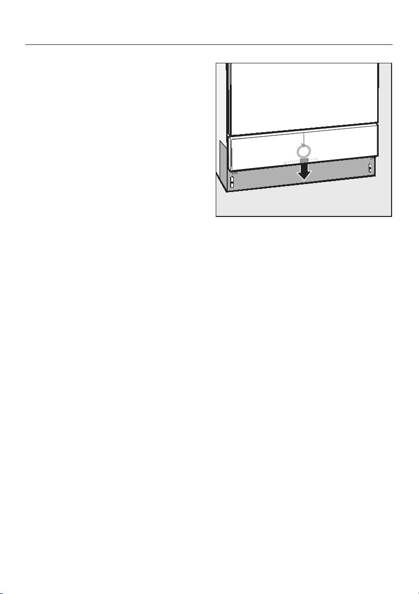
Opening the machine during a
power failure
The emergency release should only
be used when the door cannot be
opened normally, e.g. in the case of
a power failure.
Turn the program selector to "Stop"
^
f.
Press the "On/Off" button to turn the
^
machine off.
Frequently asked questions
^
Reach behind the service panel and
pull the ring of the emergency
release downwards.
37
Page 38

After Sales Service
In the event of a fault which you cannot
correct yourself, please contact the
Miele Technical Service Department
U 1-800-991-9380
techserv@mieleusa.com
V 1-800-565-6435
service@miele.ca
Please quote the model and serial
number of your machine. This
information can be found on the data
plate located on the rear of the
machine.
38
Page 39

INSTALLATION INSTRUCTIONS
Page 40

Caring for the environment
Disposal of the packing
material
The protective packing materials are
environmentally safe and can be
recycled.
Ensure that any plastic wrappings,
bags, etc. are disposed of safely and
kept out of the reach of children.
Danger of suffocation!
Disposal of the appliance
Appliances contain materials which can
be recycled. Please contact your local
authorities about recycling in your area.
Ensure that the machine presents no
danger to children while being stored
for disposal. See "Important Safety
Instructions".
40
Page 41

Installation
Please refer to the installation
diagram supplied with the machine.
Furniture and fittings installed
,
near the machine must be of a
commercial standard (able to
withstand the effects of steam).
Installation options
Free-standing
–
Undercounter
–
The machine can be installed under a
continuous counter or sink drain. The
recess must be at least 60 cm wide,
60 cm deep and 82 cm high.
Positioning and securing the
machine
To ensure stability, the machine must be
aligned and screwed to the counter.
Open the door.
^
Secure the machine to the front edge
^
of the worktop using the screws to
the left and right of the front trim.
When not mounted undercounter,
^
floor mounting brackets must be
used.
Do not use silicone sealant to seal
the gaps between the machine and
any neighboring units. This will
hinder ventilation to the circulation
pump.
Steam Deflector (protects the
countertop)
Depending on the requirements for an
undercounter installation, a steam
deflector can be ordered from the Miele
Technical Service Department.
The underside of the countertop is
protected from steam damage by a
stainless steel plate.
41
Page 42

Installation
Removing the lid (if necessary)
If necessary, remove the lid from the
machine to make installation possible.
Open the door.
^
^ Remove the fixing screws on the left
and right sides using a phillipshead
screwdriver.
^ Pull the machine lid approx. 5 mm
forwards, lift it upwards and remove.
Important for machines with steam
condenser (depending on model)
To prevent countertop damage by
^
steam, the supplied self adhesive
protective foil (25 x 58 cm) must be
placed underneath the countertop
near the steam condenser.
42
Page 43

Plumbing
Water inlet
The machine must be connected to
^
the water supply in accordance with
local and national regulations.
The washer is constructed so it may
^
be connected to a supply without an
extra non-return valve, unless
required by code.
An acceptable water pressure (flow
^
rate) is 10 - 147 psi. However, the
recommended pressure is
25 - 60 psi.
If the water pressure is below 30 psi,
the fill time will take longer.
If the "Fill/Drain" fault code "F..E" is
displayed, contact the Technical
Service Department.
^ The machine is supplied to be
connected to a standard cold (coded
blue) or hot (coded red) water supply
to a maximum temperature of 158 °F
(70 °C.)
Connect the water intake hoses to the
cold and hot water faucets.
If no hot water supply is available, the
hot water intake hose with the red
marking needs to be connected to
cold water by a y-adapter.
Water valves with
^
3
/4" male hose
thread are to be provided on site.
They should be easily accessible so
the water supply can be turned off if
necessary.
The inlet hoses are 5
^
long, terminating in a
½
feet (1.7 m)
3
/4" female hose
thread. The water inlet filters in the
threads must not be removed.
Large surface area filters are
^
enclosed in the kit supplied with the
machine.
Install these filters between the water
valve and the water inlet hose (see
illustration in "Machine Care/Cleaning
the filters in the water inlet"). The
large surface area filter for DI water is
made from stainless steel and can be
recognized by its matte surface.
For a DI water connection (H
pure), see the next page.
O
2
,
Do not cut the inlet hose or
damaged it in any way.
^
See the supplied installation diagram.
43
Page 44

Plumbing
DI-Water connection
The machine comes with a standard
connection for a pressure-resistant
system. The recommended water
pressure (flow rate) is 25 - 60 psi
however, water pressure of 10 - 147 psi
is acceptable.
The DI pressure-tested hose (marked
^
"H
O pure") with a3/4" hose thread
2
must be connected to the on-site
water valve for DI purified water.
If the DI water connection is not
used, the electronics needs to be
reprogrammed by a Miele technician.
The water intake hose remains at the
rear side of the machine.
44
Page 45

Drainage
The drainage system is fitted with a
^
non-return valve which prevents dirty
water from flowing back into the
machine via the drain hose.
The machine should preferably be
^
connected to a separate drainage
system onsite.
If separate drainage is not available
contact your Miele application
specialist for advice.
The onsite drain connection point
should be located between 1 ft.
(0.3 m) and 3 ft. (1 m) above the
lower edge of the machine.
If it is lower than 1 ft. (0.3 m), lay the
hose in a curve at a height of at least
1 ft. (0.3 m).
The drainage system must be able to
take a minimum drainage flow of
16 l/min.
Plumbing
^ The drain hose is approx. 5 ft. (1.5 m)
long, is flexible and has an internal
diameter of
not be shortened. Hose clamps are
supplied for securing it in position.
^
A longer drain hose (up to 12 ft. [4 m]
long) is available to order from the
Miele Technical Service Department.
^
The drainage system must not
exceed 12 ft. (4 meters).
^
See the supplied installation diagram.
7
/8in. (22 mm). It must
45
Page 46

Electrical connection
All electrical work must be
,
performed by a qualified person in
accordance with local and national
safety regulations.
The machine comes equipped for
connection to a 208 V, 60 Hz, 3 phase
power supply. It is equipped with a 6 ft.
long, 12/4 AWG power cord, without a
plug. A plug, rated for the required
power which will fit the receptacle, is to
be supplied by the electrician doing the
installation. It should be connected to
the main power supply.
Voltage: 208 V, 3 phase
Frequency: 60 Hz
Rated Load: 6 kW
Circuit breaker: 3 x 20 A
It can be converted to use a single
phase power supply in accordance
with the conversion and wiring diagram.
The cord must be changed from a
12/4 AWG to a 10/3 AWG. Contact
Miele Technical Service for more
information
Voltage: 208 V, 1 phase
Frequency: 60 Hz
Rated Load: 6 kW
Circuit breaker: 2 x 30 A
Connection should be made via a
^
suitable isolator, with an "On/Off"
button easily accessible for servicing
work.
^ A damaged power cord must only be
replaced with a genuine Miele cord
by a Miele service technician.
Black : connect to L1 (hot)
Red: connect to L2 (hot)
White: connect to L3 (hot)
Green: connect to GND (ground)
46
WARNING
THIS APPLIANCE MUST BE
GROUNDED
Page 47

Electrical connection
Grounding connection
The ground lead must be connected
^
to the screw connection point
(marked with the ground symbol 8) at
the back of the machine.
The machine must only be operated
with the voltage, frequency and
fusing shown on the data plate
located on the rear of the machine,
and on the plinth (behind the service
panel).
Removing the service panel
Disconnect the machine from the
main electrical supply.
Remove the fixing screws, a, from
^
the service panel.
Hold the service panel at both sides
^
and pull upwards.
Unscrew the facing, b. Remove the
^
plastic protective cap.
See the supplied installation diagram.
^
Re-assembling the service
panel
^ Refit the plastic protective cap,
facing and service panel in the
reverse order to which they were
removed.
The conversion diagram and the
wiring diagram is secured to the inner
side of the service panel.
47
Page 48

Technical data
English Metric
Height: 33
Width: 23
Depth: 23
Voltage: 208 V
Power cord approx. 5’ 11" 1.8 m
Water pressure (flow rate):
Recommended 25 - 60 psi 1.72 - 4.13 bar
Acceptable 10 - 147 psi .7 - 10 bar
Cold or Hot water
connection: up to max. 158°F 70 °C
D1 water connection:
Recommended 25 - 60 psi 1.72 - 4.13 bar
Acceptable 10 - 147 psi .7 - 10 bar
½
" (32½") 85 (82) cm
½
" 60 cm
½
" 60 cm
Delivery head: min. 12" 0.3 m
max. 39
3
/8"1 m
Drainage length: max. 13’ 1" 4 m
Water intake hose approx. 5’ 7" 1.7 m
Drain hose: approx. 4’ 7" 1.4 m
Noise level in dB (A):
Sound pressure level LpA At machine 1 m (39
Free stand unit: 64.8 52.9
Built under counter: 62 50.1
3
/8") away
484950
Page 49

Page 50

Page 51

51
Page 52

All rights reserved / 1104
This paper has been bleached without the use of chlorine.
M.-Nr. 05 893 780 / 01
 Loading...