


Operating Instructions
G 7782 CD
Washer/Disinfector
To prevent accidents
and reduce the risk of
damaging the machine,
read the Operating Instructions before
installing or using the machine. M.-Nr. 04 666 564
U

Contents
Guide to the machine
Indications for use
High-level disinfection . . . . . . . . . . . . . . . . . . . . . . . . . . . . . . . . . . . . . . . . . . . . . . . 6
Cleaning without disinfection. . . . . . . . . . . . . . . . . . . . . . . . . . . . . . . . . . . . . . . . . . 7
WARNINGS AND SAFETY INSTRUCTIONS
Installation
Electrical connection
Plumbing
Help to protect our environment
Adjusting the water softener
Opening and closing the door
Loading the washer/disinfector
Loading accessory baskets/inserts . . . . . . . . . . . . . . . . . . . . . . . . . . . . . . . . . . . . 20
Loading the washer/disinfector . . . . . . . . . . . . . . . . . . . . . . . . . . . . . . . . . . . . . . . 21
Loading examples . . . . . . . . . . . . . . . . . . . . . . . . . . . . . . . . . . . . . . . . . . . . . . . . . 21
Adjustable upper basket . . . . . . . . . . . . . . . . . . . . . . . . . . . . . . . . . . . . . . . . . . . . 24
Loading instructions for MIS injector mobile unit E-450
WARNINGS AND SAFETY INSTRUCTIONS
Adding Neutral pH Detergent
Priming the neutralizer dispensing system . . . . . . . . . . . . . . . . . . . . . . . . . . . . . . 30
Adding detergent
Adding liquid detergent. . . . . . . . . . . . . . . . . . . . . . . . . . . . . . . . . . . . . . . . . . . . . 32
Priming the liquid dispensing system . . . . . . . . . . . . . . . . . . . . . . . . . . . . . . . . . . 33
Cycle selection
Washer/Disinfector operation
Cycle Operation . . . . . . . . . . . . . . . . . . . . . . . . . . . . . . . . . . . . . . . . . . . . . . . . . . 36
Cycle phase indicators . . . . . . . . . . . . . . . . . . . . . . . . . . . . . . . . . . . . . . . . . . . . . 37
Selecting an additional cycle. . . . . . . . . . . . . . . . . . . . . . . . . . . . . . . . . . . . . . . . . 37
Interrupting a cycle . . . . . . . . . . . . . . . . . . . . . . . . . . . . . . . . . . . . . . . . . . . . . . . . 38
2

Contents
Unloading the washer/disinfector
Programming special functions
Reactivating the water softener
Cleaning and care
Maintaining the filter assembly . . . . . . . . . . . . . . . . . . . . . . . . . . . . . . . . . . . . . . . 44
Maintaining the dispensing system . . . . . . . . . . . . . . . . . . . . . . . . . . . . . . . . . . . . 45
Maintaining the drying unit . . . . . . . . . . . . . . . . . . . . . . . . . . . . . . . . . . . . . . . . . . 46
Correcting minor problems
3

Guide to the machine
1 CHECK WATER INLET/DRAIN
indicator light
2 REACTIVATE WATER SOFTENER
indicator light
3 ADD LIQUID
indicator light
4 ADD NEUTRALIZING AGENT
indicator light
DETERGENT
5 Cycle phase indicator lights
6 Indicator display field
7 Door release button
8 On-Off button
9 Cycle selector touch pads
4

Guide to the machine
10 Dispenser for detergent (blue) and
neutralizing agent (red)
11 Filter assembly
12 Safety fuse (anti-block feature) for
Drying unit
13 Operating hours counter for
Drying unit
14 Temperature selector for
Drying unit
15 Service panel
16 Dispenser for liquid
with dosage selector
17 Level indicator
18 Filter combination
19 Salt container socket
(water softener)
surfactant
5

Indications for use
High-level disinfection
The G 7782 CD Washer/Disinfector is
suitable for automatic treatment of med
ical instruments and accessories. It
cleans and, when using the disinfection
cycles simultaneously, thermally disin
fects at 200°F (93°C) instruments and
accessories.
Areas of effectiveness are physical re
moval or thermal inactivation of vegeta
tive bacteria including mycobacteria,
fungi, fungal spores, and viruses.
These categories include the Mycobac
terium tuberculosis and the
Enterococcus faecium.
IMPORTANT: Only the cycles labeled
‘DISINFECTION’ disinfect! Only use
these cycles when handling contaminated items. All other cycles are designed to clean items without disinfecting them!
The G 7782 CD Washer/Disinfector
achieves high-level disinfection as
defined by the Spaulding categoriza
tion.
-
-
-
IMPORTANT: Centers for Disease Con
trol Publication PB85-923404,
for Handwashing and Hospital Environ
-
mental Control, 1985,
cessing requirements for critical,
semicritical and non-critical instru
ments. Refer to these definitions to de
termine when and under what condi
tions the G 7782 CD Washer/Disinfector
can be used.
-
Instruments Suitable for Processing
in the Washer/disinfector
-
All instruments, accessories, and other
items to be cleaned and disinfected in
the G 7782 CD Washer/Disinfector must
have the following properties:
^ Heat resistance to temperatures of at
least 200°F (93°C)
^ Corrosion resistance in the presence
of heat, alkalinity and water.
Certain items and materials are not
suitable for processing in the
Washer/disinfector.
Do not process:
defines the pro
Guideline
-
-
-
-
-
-
^
carbon steel devices as they may
corrode;
^
flexible endoscopes, light cables, fi
ber optics, rotating devices, motors
or other electrical equipment unless
the processing is approved by the
device manufacurer.
6
-

Indications for use
NOTE:
Aluminium devices can only be
processed using the DISINFECTION
VARIO 93°C - 10 MIN cycle with Neutral
PH Detergent as they may discolor oth
-
erwise.
NOTE:
ufacturer to confirm processing com
Always contact the device man
-
-
patibility if you have any concerns
about the suitability of a specific item.
The G 7782 CD Washer/Disinfector is
an effective processor for many medi
cal instruments and accessories. It is
an efficient washer and, when a disin
fection cycle has been selected, it ther
mally disinfects at 200°F (93°C).
WARNING - POTENTIAL
BIOHAZARD: Always use DISINFECTION cycles when processing medical instruments and accessories.
Only DISINFECTION cycles provide
high levels of disinfection.
-
-
-
Cleaning without disinfection
All other cycles are designed to clean
goods without disinfecting them. These
programs are:
RINSE
^
WASH 93°C
^
Please refer to "Cycle selection" for de
tailed information.
-
7

WARNINGS AND SAFETY INSTRUCTIONS
The following is a summary of the safety precautions which must be observed
when operating and servicing this equipment. These precautions are repeated (in
whole or in part), where applicable throughout the manual.
All relevant safety procedures must be obeyed. Relevant safety procedures
include, but are not limited to, the Centers for Disease Control’s Recom
mended Infection Control Practices and the OSHA Bloodborne Pathogens
Standard.
-
READ ALL INSTRUCTIONS BEFORE
USING THE APPLIANCE
WARNING -
The manufacturer cannot accept responsibility for damage caused when the
appliance is not used according to the instructions, or for uses other than
those for which it was intended.
The manufacturer cannot be held responsible for problems or injuries resulting from improper installation, use or operation of this equipment.
8

WARNINGS AND SAFETY INSTRUCTIONS
WARNING - PERSONAL INJURY
HAZARD: Do not allow small chil
dren or unauthorized personnel access
to the washer/disinfector or its controls.
WARNING - EXPLOSION
HAZARD: Do not install the
washer/disinfector in areas where flam
mable compounds/vapors are
present.
WARNING - PERSONAL INJURY/
EQUIPMENT DAMAGE HAZARD:
Repair work must be carried out only by
a qualified and competent service tech
nician. Repairs by unqualified persons
or installation of unauthorized parts
could cause personal injury, result in
costly equipment damage or void the
washer/disinfector warranty.
WARNING - BURN HAZARD:
Except for emergency, do not open
door when cycle is in process. In an
emergency, first stop the cycle by
pressing ON/OFF button. Press DRAIN
touch pad and wait for
washer/disinfector to drain. Wear pro
tective gloves and face shield when
ever reaching into wash cabinet.
-
-
-
WARNING - ELECTRICAL SHOCK
HAZARD: Disconnect all utilities to
equipment before servicing. Do not ser
vice equipment unless all utilities have
been properly locked out.
WARNING - PERSONAL INJURY
-
-
HAZARD: The water in this
washer/disinfector is not suitable for
drinking.
WARNING - PERSONAL INJURY/
EQUIPMENT DAMAGE HAZARD:
Only use detergents which have been
approved of by Miele. Use of any other
products may cause personal injury, in
validate the disinfection results or void
the washer/disinfector warranty.
WARNING - CHEMICAL BURN
HAZARD: Wear protective gloves
and goggles and use care when handling liquids such as detergents or neutralizing agents. Read and follow the instructions and safety procedures on the
packaging and in the Material Safety
Data Sheet (MSDS).
-
-
9

WARNINGS AND SAFETY INSTRUCTIONS
WARNING - PERSONAL INJURY/
EQUIPMENT DAMAGE HAZARD:
Empty containers and glassware before
placing in the washer/disinfector. Do
not allow any acids or solvents, espe
cially hydrochloric acid and chlorides,
to get into the wash cabinet.
WARNING - PERSONAL INJURY
HAZARD: Be careful when sorting
instruments with sharp pointed ends. If
possible, place the pointed end down
wards.
WARNING - PERSONAL INJURY/
EQUIPMENT DAMAGE HAZARD:
Internal cleaning and disinfecting to a
measurable standard can only be
achieved with instruments that can be
dismantled and where the jets, sleeves
and adapters are used appropriately. A
special examination, over and above a
visual one, of the cleanliness of the inner area of the instruments should be
made. Minimally invasive surgical (MIS)
instruments should preferably be processed using the DISIN VARIO 93°C-10
MIN or DISIN 93°C-10 MIN program
with recommended detergents.
-
-
WARNING - BURN HAZARD: Allow
accessories to cool to room tem
perature before unloading. Any water
which may have collected in incorrectly
loaded items will be very hot and
should be emptied into the wash cabi
net.
WARNING - BURN HAZARD:
Do not touch the heating elements
in wash cabinet after the end of a cycle.
WARNING - TIPPING HAZARD: Do
not sit or lean on the open door.
This could cause the washer/disinfector
to tip.
WARNING - FALL HAZARD:
To prevent falls, keep floors dry by
immediately wiping up any spilled liquids in washer/disinfector loading and
unloading areas.
WARNING - ELECTRIC SHOCK
HAZARD: Washer/disinfector must
be correctly grounded!
WARNING - POTENTIAL
BIOHAZARD: Always use DISIN
FECTION cycles when processing
medical instruments and accessories.
Only DISINFECTION cycles provide
high levels of disinfection.
-
-
-
10

WARNINGS AND SAFETY INSTRUCTIONS
WARNING - PERSONAL INJURY/
EQUIPMENT DAMAGE HAZARD:
Do not fill container with cleaning deter
gent! Fill with reactivation salt only! Oth
erwise the pressurized container may
cause injuries by unscrewing.
CAUTION: Washer/disinfector must
not be used without all filters in
place.
CAUTION: Use only accessories
specifically designed for this
equipment. Load accessories into
washer/
disinfector in accordance with the in
structions provided.
CAUTION: The operator is respon-
sible for monitoring and guaranteeing the standard of disinfection in the
routine disinfection cycle. Disinfection
parameters should be checked regularly using chemical indicators, and
contamination levels checked and documented periodically using biological
indicators.
-
-
-
SAVE THESE
INSTRUCTIONS
11

Installation
WARNING - EXPLOSION HAZARD:
Do not install the washer/disinfector
in area where flammable com
-
pounds/vapors are present.
IMPORTANT: The machine should only
be installed by a competent contractor.
The contractor should be experienced
in installing machines that require elec
trical hook-up as well as plumbing.
The machine can be installed in the fol
lowing ways:
Free-standing
^
^ Under counter.
The recess should be at least
3
23-
/4" (60 cm) wide, 23-3/4" (60 cm)
deep, and 33-
1
/4" (85 cm) high.
Washer/disinfector can be built into a
recess of 32-
1
/4" (83 cm) high by re-
moving the washer/disinfector top.
If necessary the washer/disinfector top
can be removed as follows:
-
-
^ Open the door.
^ Remove the screws on the left and
right, using a Philips screw driver.
^ Pull the top forward, lift and remove.
12

Installation
To re-assemble:
Replace plastic protective cap,
^
kickplate facing and service panel in
the reverse order which they were re
moved.
Make sure the grounding lead is
^
re-connected.
Do not use silicone sealant to seal
^
the gaps between the machine and
any neighboring units as this will hin
der ventilation to the circulation
pump.
-
-
The machine must be installed and leveled correctly. Any unevenness in the
floor can be compensated for by
screwing the adjustable feet in or out as
necessary. To level this unit, the service
panel and kickplate must first be removed.
To remove the service panel and
kickplate:
^
Take hold of the service panel at the
top of both sides and pull forward.
^
Remove all four kickplate screws.
^
Disconnect grounding lead if
ne-cessary.
^
Remove plastic protective cap.
Depending on the installation require
ments, the following kit is available:
Steam deflector
For use where the machine will be installed under a wooden countertop.
The underside of the work surface is
protected from steam damage by a
plate of stainless steel.
-
13

Electrical connection
IMPORTANT: All electrical work must
be carried out by a qualified electrician
and in compliance with all local and na
tional electrical codes.
Before making any connections, check
that the voltage shown on the data
plate corresponds to your power sup
ply. Data plate is located on back of
unit and behind service panel.
The washer/disinfector is supplied as
standard for connection to a 208 V,
60 Hz, single phase power supply and
is fitted with a power supply cord 6 ft
(1.8 m) long with a cross-section of
AWG 10-4. Connect washer/disinfector
to the main power supply (junction box
or electrical cord to outlet) according to
the opposite chart.
-
-
NOTE:
If an electrical cord is used,
make sure cord is the proper size and
voltage/current rating for the washer/
disinfector as identified on the data
plate.
Voltage: 208 V, single phase
Frequency: 60 Hz
Rated load: 6.0 kW
Circuit breaker: 30 A per phase
The washer/disinfector can be con
verted for connection to a 3-phase
power supply.
WARNING - ELECTRICAL SHOCK
HAZARD: Washer/disinfector must
be correctly grounded!
14
-
The wiring diagram
hind the kickplate on the left hand side,
attached to the floor of the machine.
The data plate
numbers is on the rear of the machine
and on the kickplate behind the service
panel.
can be found be
with serial and model
-

Connection to the cold water inlet
The machine must be connected to
^
the water supply in accordance with
all local and national plumbing
codes.
The machine is constructed with an
^
air gap/anti-siphoning device on both
the intake and the drain sides. No
such additional devices are neces
sary or recommended, as they will
impede the water inflow into and out
of the washer.
The water pressure must be between
^
35 and 145 psi (2.5 - 10.0 bar). If the
water pressure is not within this
range, the Miele Technical Service
Department can advise you of the
measures to be taken (see "Programming special functions").
^ This machine is designed for cold
water connection only. Both inlet
hoses (water supply and steam condenser) must be connected to the
valves for cold water. Cold water sup
ply must be provided with shut off
valves (by others).
^
Valves with 3/4’’ male hose thread
should be provided near the washer,
and should be easily accessible.
^
For additional protection of the valves
against impurities in the water supply,
large surface area filters are en
closed in the kit supplied with the
machine (see diagram in "Cleaning
and care, Maintaining the filter as
sembly").
-
Plumbing
Hose Color Water type
Blue
Green
WARNING - PERSONAL INJURY
HAZARD: The water in the washer/
disinfector is not suitable for drink
-
-
ing.
Drainage
The drain system is equipped with a
^
non-return valve which prevents dirty
water from flowing back into the
washer/disinfector.
^ The machine is supplied with two
5 ft (1.5 m) long flexible drain hoses
with an inner diameter of 3/4’’ (2 cm).
They should not be shortened or attached to any fittings that would
cause a reduction in water flow.
^ Longer drain hoses up to a length of
13 ft (3.3 m) are available if required.
-
^
Both hoses can be attached to exist
ing drain lines through the use of a
1-1/2’’ (3.5 cm) or larger stand pipe /
P-trap combination. Alternately, the
hoses can be connected directly to
existing drain lines, provided any fit
tings or adapters used do not reduce
the water flow.
^
The drain hoses must not exceed
13 ft (3.3 m) in length, or be attached
to the main drain at a point higher
than 3 ft (1m) above the floor.
^
A floor drain is permissible.
Cold water
Demineralised water
-
-
-
15

Help to protect our environment
Disposal of the packaging material
The transport and protective packaging
is mostly manufactured from the follow
ing reusable materials:
corrugated paper/cardboard
^
polystyrene (CFC-free)
^
polyethylene foil (transparent)
^
untreated wood
^
Rather than throwing these materials
away, please take them to the nearest
recyclables collection point.
Disposal of your old machine
Old machines contain materials which
can be recycled. Please contact your
local salvage yard about potential recy
cling options before disposal.
Before disposing, run the DRAIN pro
gram to make sure that no residual flu
ids are left in the sump of the machine.
When disposing of an old machine,
make sure the door catch is removed.
This will prevent children at play from
being accidentally locked in.
-
-
-
16

Adjusting the water softener
To avoid the build-up of calcium depos
its on items being cleaned and disin
fected in the washer/disinfector, the
water may need to be softened (where
the supply hardness exceeds 107 ppm
CaCO3).
To ensure a steady supply of soft water,
the water softener must always be:
correctly set
–
regenerated with salt as soon as the
–
REACTIVATION indicator light comes
on.
The water softener should be set to cor
respond with the water hardness upon
installation of the washer/ disinfector.
Your local water authority can advise
you on the water hardness in your ara.
Setting the water softener
The hardness range is divided into 18
units and a zero position. The washer/
disinfector is set at the factory for a
water hardness setting of 8, corre
sponding to 339 ppm CaCO3. If your
water supply is harder or softer than
this, change the setting as follows:
°d
Time
set
-
ting
18
17
-
16
15
14
13
12
11
10
9
8
7
6
5
4
3
2
1
0
mmol/l° f °e ppm
gr/gal
10.7
12.5
14.3
16.0
17.9
19.6
21.4
23.2
26.8
30.4
33.9
39.3
42.8
50.0
57.1
67.8
85.7
126,7
10
11
12
13
15
17
19
22
24
28
32
38
48
71
1.07
6
1.25
7
1.42
8
1.60
9
1.78
1.96
2.14
2.31
2.67
3.03
3.38
3.92
4.27
4.98
5.70
6.76
8.54
12.64
7.5
8.8
10.0
11.3
12.5
13.8
15.0
16.3
18.8
21.3
23.8
27.5
30.0
35.0
40.0
47.6
60.1
88.9
-
CaCO
3
107
125
143
160
179
196
214
232
268
304
339
393
428
500
571
678
857
1267
17

Adjusting the water softener
1. Using table provided, identify correct
"Display Field" number that corre
sponds to your local water hardness.
2. Press the DRAIN and DRYING touch
pads simultaneously and, while de
pressed, turn the machine on, using
the main ON/OFF switch.
"P3" will appear in the display field.
3. Press the REACTIVATION touch pad.
The "P3" will disappear and setting
"0" will appear in the display field.
4. Press the DRYING touch pad as
many times as necessary for the de
sired value to appear in the display
field.
5. Press the START touch pad.
"SP" appears in the display field.
6. Press START once more. The setting
will now be stored. The display field
clears.
The washer/disinfector is now ready for
operation.
-
-
If the water hardness in your area is
permanently below 107 ppm CaCO3,
you do not need to soften the water.
Please deactivate the water softener by
selecting the setting "0" in the display
field according to above instructions.
The REACTIVATION indicator light will
not come on and the water softener will
not need to be reactivated.
For instructions on reactivating the
water softener, see "Reactivating the
water softener".
-
18

Opening and closing the door
To open the door
Press the DOOR button on the control
^
panel and open the door.
WARNING - BURN HAZARD: Except
for emergency, do not open door
when cycle is in process. In an
emergency, first stop the cycle by
pressing ON/OFF button. Press
DRAIN touch pad and wait for
washer/disinfector to drain. Wear
protective gloves and face shield
whenever reaching into wash cabi
net.
The door should only be opened during
cycle operation for emergencies, e.g. if
articles are knocking together. (Refer to
"Interrupting a cycle".)
WARNING - TIPPING HAZARD: Do
not sit or lean on open door.
-
To close the door
Lift the door upwards and push until
^
it clicks into position. Do not press
the DOOR button.
19

Loading the washer/disinfector
CAUTION: Use only accessories
specifically designed for this equip
ment.
The washer/disinfector normally uses
an upper and a lower basket.
Depending on the type and shape of
the items being cleaned, accessory
baskets and inserts can be utilized. Se
lect baskets and inserts which are ap
propriate for the application (see sepa
rate product literature).
-
-
Loading accessory
baskets/inserts
WARNING - PERSONAL INJURY/
EQUIPMENT DAMAGE HAZARD:
Empty containers and glassware before placing in the
washer/disinfector. Do not allow any
acids or solvents, especially hydrochloric acid and chlorides to get into
the wash cabinet.
1. Empty all items to be cleaned before
loading into the accessories.
2. Remove gross soil/debris from all
items to be cleaned before loading
into accessories.
3. Load the items to be cleaned so the
water will come into contact with all
surfaces. This ensures that they will
be properly cleaned and disinfected.
Do not place items to be cleaned in
^
side other pieces where they may be
concealed.
Vessels should be inverted and
^
-
placed in the correct accessory in
serts.
Deep-based items should be placed
^
at enough of an angle for water to run
off them freely.
^ Tall and narrow pieces should be
placed in the center of the basket to
ensure good coverage with water.
4. In order to avoid corrosion, it is recommended that only heat and corrosion resistant items be cleaned in the
washer/disinfector. For the suitability
of instruments, please refer to "Indications for use".
5. The spray arms must not be blocked
by items which are too high for the
basket or which hang down in its
path. If necessary, manually rotate
the spray arm to test it.
-
-
WARNING - PERSONAL INJURY
HAZARD: Be careful when sorting
instruments with sharp pointed
ends. If possible, place pointed end
downwards.
20

Loading the washer/disinfector
Loading the washer/disinfector
WARNING - FALL HAZARD: To pre
vent falls, keep floors dry by immedi
ately wiping up any spilled liquids in
washer/disinfector loading and un
loading areas.
CAUTION: Load accessories into
washer/disinfector in accordance
with the instructions provided.
Make sure the spring loaded coupling
engages correctly when the upper bas
ket is inserted into the washer/
disinfector. There should be a tight fit
between the coupling and the water inlet connector at the top of the chamber.
If there is not, adjust the adapter as follows:
^ Loosen the holding ring on the upper
basket.
^ Push up the adapter so it is 1/4’’
higher than the water inlet connector,
and tighten the holding ring.
-
-
-
Loading examples
Miele offers a wide variety of baskets
and inserts for all kind of medical appli
cations. For more information, please
see the separate product literature.
-
-
21
Loading the washer/disinfector
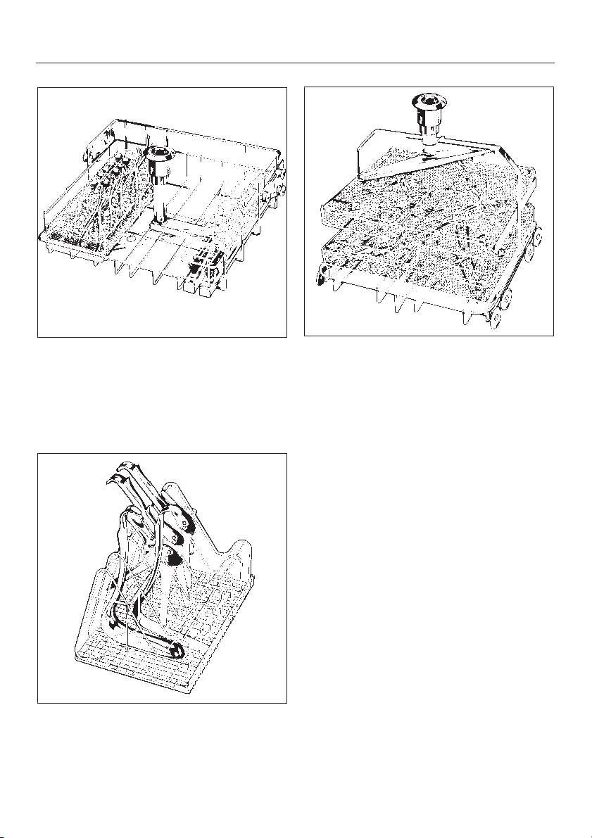
E-147
Upper basket with 28 injection nozzles
Features 28 jets/funnels for direct injection of water into loaded hollow instruments like syringe tips or evacuation tips.
E-414
1
/4ENT Insert
E-327
2-Level Mobile Unit (empty)
with 2 levels for mesh trays.
For speculae used in gynaecological
applications. Load as illustrated.
22
Loading the washer/disinfector
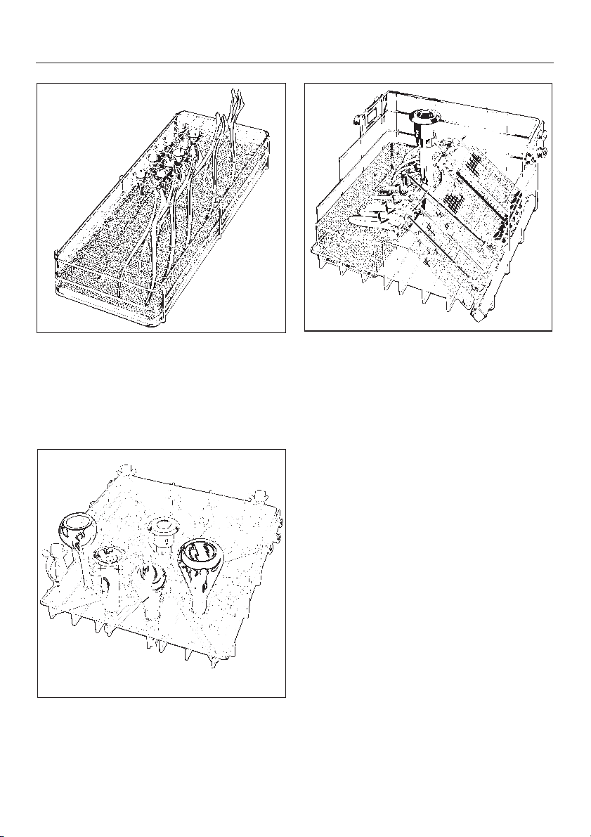
E-417
2
/5ENT Insert
For ear and nose speculae. Load as
illustrated to ensure that speculae are
open for cleaning.
O-175
Direct Injection Upper basket with 34
spray nozzles
Features 34 jets for cleaning glass
ware.
E-176
Upper basket with Drying Connection
for rigid endoscopes
Right-hand side: 14 jets/funnels for
parts of rigid endoscopes, max. length
50 cm. 10 jets with clips are fitted for
catheters.
Left-hand side: mesh basket (loose).
23

Loading the washer/disinfector
Adjustable upper basket
Adjustable upper baskets can be used
in this machine. They
can be raised or lowered by
from the initial setting.In the middle po
sition, the upper basket will accommo
date:
instruments, utensils, accessories
^
and inserts up to 7
1
height
while the lower basket can accommo
date:
^ instruments, utensils, accessories
and inserts up to 9
3
height.
3
/4" (2 cm)
/2" (19 cm) in
/4" (25 cm) in
-
For further details regarding con
tainer height combinations, see table
below.
To p
basket
-
position
-
top 17 6,7 27 10,6
middle 19 7,5 25 9,8
bottom 21 8,3 23 9,0
Top basket height Bottom basket
(cm) (inches) (cm) (inches)
To adjust the upper basket
Pull out the upper basket until a resis
^
tance is felt, lift from the runners and
remove.
^ Unscrew the knurled nuts on both
sides of the basket and reposition as
necessary.
-
height
-
24
Loading instructions for MIS injector mobile unit E-450
WARNING - PERSONAL INJURY/
EQUIPMENT DAMAGE HAZARD:
Internal cleaning and disinfecting to
a measurable standard can only be
achieved with instruments that can
be dismantled and where the jets,
Important:
The "Warnings and Safety instructions" pages must be observed.
sleeves and adapters are used ap
propriately. A special examination,
over and above a visual one, of the
cleanliness of the inner area of the
instruments should be made. MIS in
struments should preferably be pro
cessed using the DISIN VARIO
93°C-10 MIN or DISIN 93°C-10 MIN
program with recommended detergents.
^ Put 5 mm and 10 mm Ø shafts into
the appropriate sleeves (E-442 or
E-443).
^ Do not load the lower levels with
more inserts than as shown above in
the example (from left to right
E-457, E-460, E-451)
-
-
-
^
Trocars of a wider diameter will be
cleaned more effectively in the front
or the rear position of the row of jets.
25

Loading instructions for MIS injector mobile unit E-450
Accessories and fittings:
1
E-451 Insert
^
for small items
E-442 5 mm Ø injection sleeve
^
E-443 10 mm Ø injection sleeve
^
E-336 MIBO sleeve
^
E-445 caps for E-442 sleeves
^
E-446 caps for E-443 sleeves
^
E-447 Adapter for Luer lock
^
(female)
E-448 Tube for Luer lock adapter
^
^ E-449 Adapter for Luer lock
(male)
^ E-452 Injector jet Ø 2.5 x 60 mm
^ E-453 Injector jet Ø 4.0x110 mm
^ E-454 Injector jet for trocar
sleeves Ø 10 x 15 mm
/6mesh trays
^ E-464 Irrigation adapter can
be combined with the
E-454 for trocar sleeves
>15 mm Ø
^
E-456 Spring to hold instruments
open
^
E-362 Blanking screw
^
E-457 Insert for functional parts
^
E-444 Insert for fibre optic
(coldlight) cable or suction
hose
^
E-460 Insert for rigid optics
26

WARNINGS AND SAFETY INSTRUCTIONS
G 7782 CD Washer/Disinfector
To the person responsible for the machine:
Make this pull-out with the Warning and Safety Instructions available to any
^
operators of the machine. Place it near the machine, where it can be seen.
Ensure that operators know and understand these Warning and Safety Instruc-
^
tions, and observe them in use.
The following is a summary of the safety precautions which must be observed
when operating and servicing this equipment. These precautions are repeated (in
whole or in part), where applicable throughout the manual.
All relevant safety procedures must be obeyed. Relevant safety procedures
include, but are not limited to, the Centers for Disease Control’s Recom
mended Infection Control Practices and the OSHA Bloodborne Pathogens
Standard.
-
READ ALL INSTRUCTIONS BEFORE
USING THE APPLIANCE
WARNING -
The manufacturer cannot accept responsibility for damage caused when the
appliance is not used according to the instructions, or for uses other than
those for which it was intended.
The manufacturer cannot be held responsible for problems or injuries result
ing from improper installation, use or operation of this equipment.
-
1

WARNINGS AND SAFETY INSTRUCTIONS
WARNING - PERSONAL INJURY
HAZARD: Do not allow small chil
dren or unauthorized personnel access
to the washer/disinfector or its controls.
WARNING - EXPLOSION HAZARD:
Do not install the
washer/disinfector in areas where flam
mable compounds/vapors are present.
WARNING - PERSONAL INJURY/
EQUIPMENT DAMAGE HAZARD:
Repair work must be carried out only by
a qualified and competent service tech
nician. Repairs by unqualified persons
or installation of unauthorized parts
could cause personal injury, result in
costly equipment damage or void the
washer/disinfector warranty.
WARNING - BURN HAZARD:
Except for emergency, do not open
door when cycle is in process. In an
emergency, first stop the cycle by
pressing ON/OFF button. Press DRAIN
touch pad and wait for
washer/disinfector to drain. Wear protective gloves and face shield when
ever reaching into wash cabinet.
-
-
WARNING - PERSONAL INJURY
HAZARD: The water in this
washer/disinfector is not suitable for
drinking.
WARNING - PERSONAL INJURY/
EQUIPMENT DAMAGE HAZARD:
Only use detergents which have been
approved of by Miele. Use of any other
products may cause personal injury, in
validate the disinfection results or void
the washer/disinfector warranty.
-
WARNING - CHEMICAL BURN
HAZARD: Wear protective gloves
and goggles and use care when han
dling liquids such as detergents or neutralizing agents. Read and follow the instructions and safety procedures on the
packaging and in the Material Safety
Data Sheet (MSDS).
WARNING - PERSONAL INJURY/
EQUIPMENT DAMAGE HAZARD:
Empty containers and glassware before
placing in the washer/disinfector. Do
not allow any acids or solvents, especially hydrochloric acid and chlorides,
to get into the wash cabinet.
-
-
WARNING - ELECTRICAL SHOCK
HAZARD: Disconnect all utilities to
equipment before servicing. Do not ser
vice equipment unless all utilities have
been properly locked out.
2
-

WARNINGS AND SAFETY INSTRUCTIONS
WARNING - PERSONAL INJURY
HAZARD: Be careful when sorting
instruments with sharp pointed ends. If
possible, place the pointed end down
wards.
WARNING - PERSONAL INJURY/
EQUIPMENT DAMAGE HAZARD:
Internal cleaning and disinfecting to a
measurable standard can only be
achieved with instruments that can be
dismantled and where the jets, sleeves
and adapters are used appropriately. A
special examination, over and above a
visual one, of the cleanliness of the in
ner area of the instruments should be
made. Minimally invasive surgical (MIS)
instruments should preferably be processed using the DISIN VARIO 93°C-10
MIN or DISIN 93°C-10 MIN program
with recommended detergents.
WARNING - BURN HAZARD: Allow
accessories to cool to room temperature before unloading. Any water
which may have collected in incorrectly
loaded items will be very hot and
should be emptied into the wash cabi
net.
-
-
-
WARNING - FALL HAZARD:
To prevent falls, keep floors dry by
immediately wiping up any spilled liq
uids in washer/disinfector loading and
unloading areas.
WARNING - ELECTRIC SHOCK
HAZARD: Washer/disinfector must
be correctly grounded!
WARNING - POTENTIAL
BIOHAZARD: Always use DISIN
FECTION cycles when processing
medical instruments and accessories.
Only DISINFECTION cycles provide
high levels of disinfection.
WARNING - PERSONAL INJURY/
EQUIPMENT DAMAGE HAZARD:
Do not fill container with cleaning detergent! Fill with reactivation salt only! Otherwise the pressurized container may
cause injuries by unscrewing.
-
-
WARNING - BURN HAZARD:
Do not touch the heating elements
in wash cabinet after the end of a cycle.
WARNING - TIPPING HAZARD: Do
not sit or lean on the open door.
This could cause the washer/disinfector
to tip.
3

WARNINGS AND SAFETY INSTRUCTIONS
CAUTION: Washer/disinfector must
not be used without all filters in
place.
CAUTION: Use only accessories
specifically designed for this
equipment. Load accessories into
washer/
disinfector in accordance with the in
structions provided.
-
CAUTION: The operator is respon
sible for monitoring and guarantee
ing the standard of disinfection in the
routine disinfection cycle. Disinfection
parameters should be checked regu
larly using chemical indicators, and
contamination levels checked and documented periodically using biological
indicators.
-
SAVE THESE
INSTRUCTIONS
-
-
4

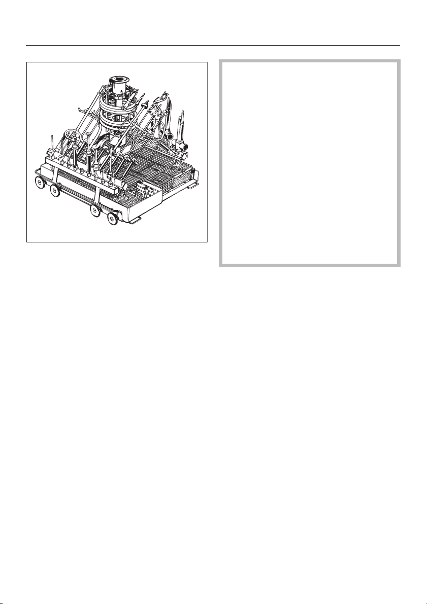
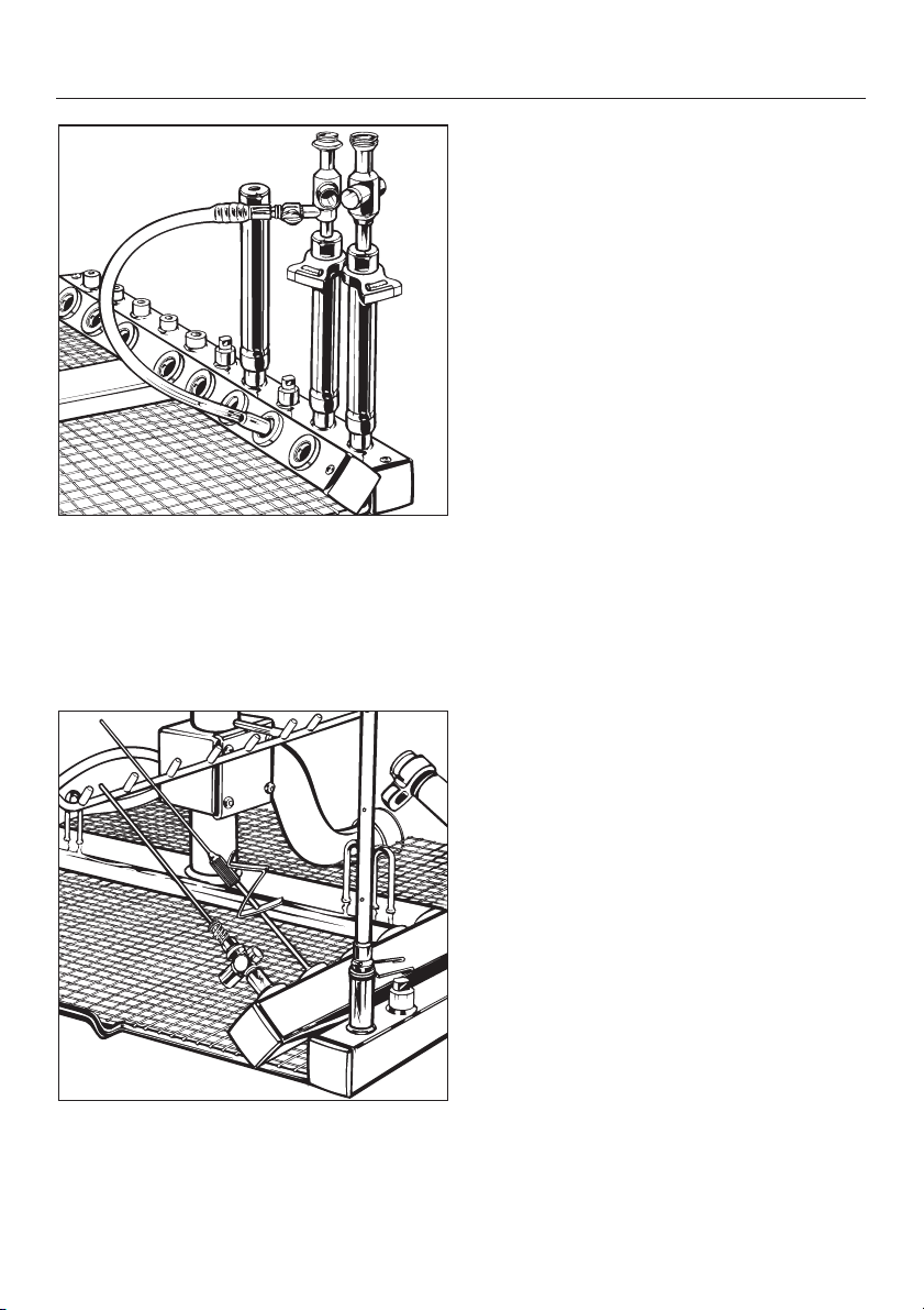
Loading instructions for MIS injector mobile unit E-450
E-457 Insert for separable MIS
instruments
^ Place the handles of modular shaft
instruments into the side compartments
^ Then clamp the connection end of
the functional parts into the plastic
clip. Open the working ends and fix
the functional part into one or two fur
ther clips.
^ Connect MIS instruments which can-
not be dismantled, and have an irrigation channel connector, to the
water circuit with the E-448 tube with
Luer lock adapters, so that they lie at
an angle.
-
27
Loading instructions for MIS injector mobile unit E-450
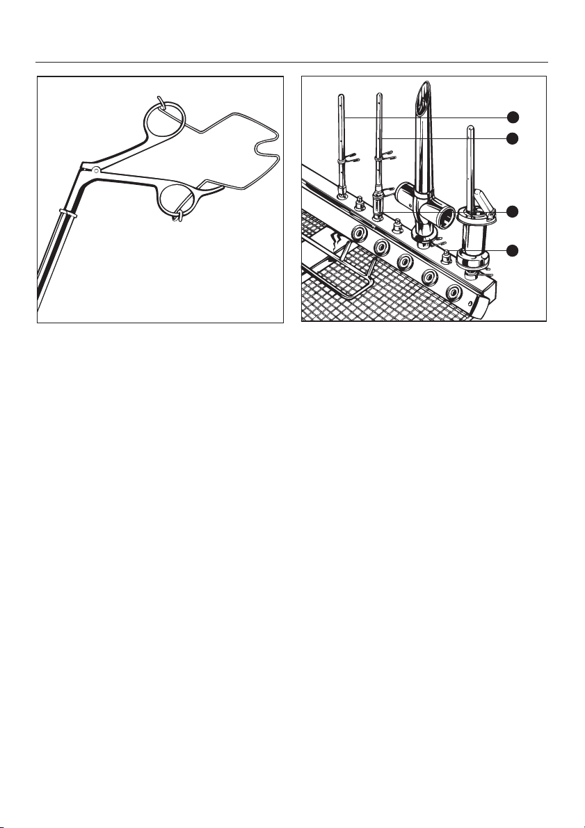
1
1
2
3
Opening spring E-456
^ For MIS instruments which are
sprung to stay closed and cannot be
taken apart, scissors, forceps etc.,
and must be held open in the wash
jet sleeve. Use the opening spring if
appropriate.
^ Take apart trocar sleeves and push
on to the corresponding injector jets.
E-454 A for Trocar sleeves
10-15 mm Ø
E-464 B with E-454 A for Trocar
sleeves >15 mm Ø.
Using the clamp springs, the sleeves
or the flap valve can be positioned in
such a way that critical areas such as
for example the side piston shoe, can
be washed by the jet openings on the
side or the jet spray of the
E-454.
^
Important:
To maintain wash pressure every o
pening must be fitted either with an
item to be cleaned or a blanking
screw C.
-
28
Loading instructions for MIS injector mobile unit E-450
Optics insert (not illustrated)
Only optics which are safeguarded
^
by the manufacturer against mechan
ical damage may be processed in
special inserts such as the
E-460 or corresponding optic manu
facturer’s inserts.
Assurance is needed from the manu
^
facturer that optics and fibre optic
(cold-light) cables can be thermally
treated. Pre-treatment conditions
must be observed. DISIN VARIO
93°C-10 MIN or DISIN 93°C-10 MIN
process with de-ionised water final
^ Fit the trocar or instrument sleeves
< 10 mm Ø into sleeve E-336 or on to
jet E-453. Trocar sleeves with a side
connection should be attached via
the E-448 tube with Luer lock adapters.
rinse.
If you have any questions relating to
applications technology:
please contact our professional advisory team at Miele.
-
-
-
^
Connect narrow (Veress) cannulae so
that they lie at an angle with Luer lock
adapters E-449, or fix on the jet with
a spring clip.
29

Adding Neutral pH Detergent
Priming the neutralizer
dispensing system
Before using the washer/disinfector for
the first time, or if the washer/disinfector
has been operated with an empty neu
tralizer container, the dispensing sys
tem must be primed. Please proceed
as follows:
1. Press the ON/OFF button to turn
washer/disinfector off.
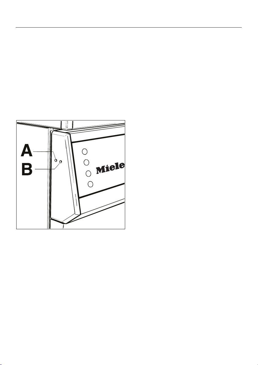
2. Using a long, thin object (e.g.,
straightened paper clip), press in
switch "A", located on the left hand
end of the control panel, for 3
utes.
1
/2 min-
-
-
Each time the system is primed, any
neutralizer which runs into the wash
cabinet must be washed out by running
the RINSE cycle.
After this cycle is run, the dispensing
system is filled and ready for use.
To reduce the pH level of the wash so
lution after the wash phase, the ma
chine dispenses neutralizer during In
terim Rinse I.
-
-
-
30
Adding Neutral pH Detergent
WARNING - CHEMICAL BURN HAZ
ARD: Wear protective gloves and
goggles and use care when han
dling neutralizing agents. Read and
follow the instructions and safety
procedures on the packaging and in
the Material Safety Data Sheet
(MSDS).
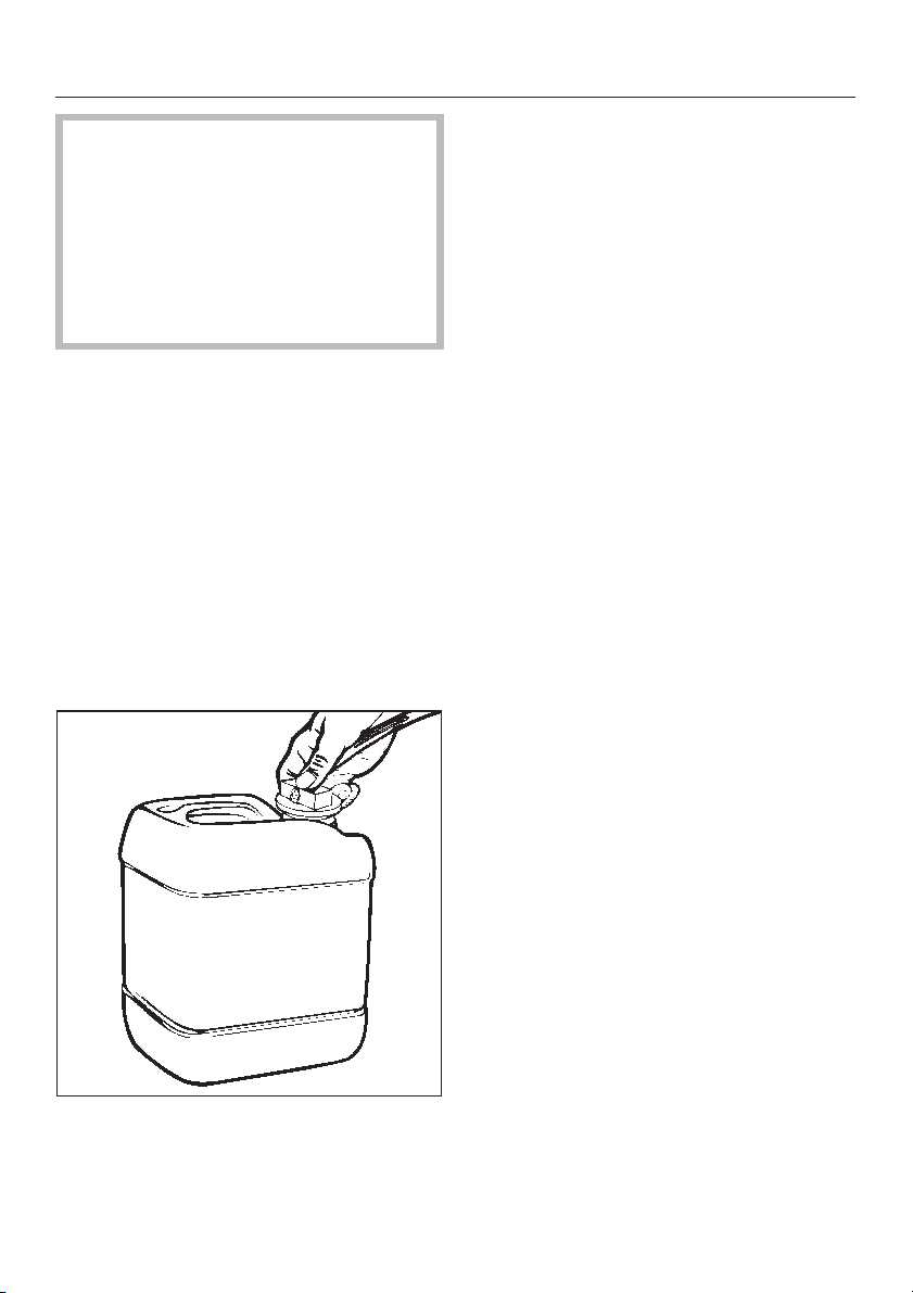
1. Place the Neutralizer container on
the floor close to the
washer/disinfector or in the optional
Dispensing Unit.
2. When the NEUTRALIZER indicator
light on the control panel lights up, fill
container with neutralizer if necessary.
3. Place the siphon tube from the neu-
tralizer dispensing pump firmly in the
opening of the Neutralizer container.
-
-
31
Adding detergent
WARNING - PERSONAL INJURY/
EQUIPMENT DAMAGE HAZARD:
Only use detergents which have
been approved by Miele. Use of any
other products may cause personal
injury, invalidate the disinfection re
sults or void the washer/disinfector
warranty.
Use of Alkaline detergent* or Neutral
pH detergent* as a liquid detergent is
recommended.
-
* Contact your Miele representative for
ordering information.
Adding liquid detergent
WARNING - CHEMICAL BURN HAZ
ARD: Wear protective gloves and
goggles and use care when han
dling liquid detergents. Read and
follow the instructions and safety
procedures on the packaging and in
the Material Safety Data Sheet
(MSDS).
Upon installation, or when the DETER
GENT indicator light comes on:
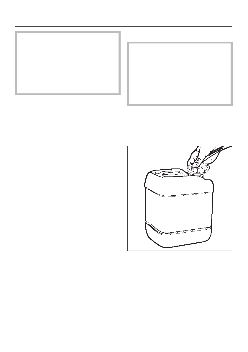
1. Replace the detergent container with
a new one.
-
-
-
32
2. Place the blue siphon tube firmly in
the opening of the detergent con
tainer (see illustration).
-
Adding detergent
Priming the liquid dispensing
system
Before using the washer/disinfector for
the first time, or if the washer/disinfector
has been operated with an empty de
tergent container, the dispensing sys
tem must be primed. Please proceed
as follows:
Press the ON/OFF button to turn the
^
washer/disinfector off.
-
-
Each time the system is primed, any
detergent which runs into the wash
cabinet must be washed out by running
the RINSE cycle.
After this cycle is run, the dispensing
system is filled and ready for use.
^
Using a long, thin object (e.g.,
straightened paper clip), press in
switch "B", located on the left hand
end of the control panel, for 3
utes.
1
/2min
-
33

Cycle selection
Cycle Application Detergent
RINSE
DISINFECTION
VARIO
93°C-10 MIN
WASH 93°C
DISINFECTION
93°C-10 MIN
To rinse heavily soiled instruments
e.g. after soaking them in a disinfecting agent
to avoid the build-up of foam in the machine.
For protein soils (such as blood and secre
tions) - for cleaning and thermal disinfection
with 90-93°C (194-200°F) and
10-minute holding time for instruments which
are susceptible to chemicals and changes in
temperature.
Cleaning of instruments at 93°C (200°F) with
3-minute holding time.
For cleaning instruments at 93°C (200°F) with
10-minute holding time.
Virucidal and bactericidal disinfection
(areas A + B) to BGA standard
-
Please follow manufacturer’s
instructions.
None
Preferably a neutral liquid de
tergent should be dispensed
Alkaline or neutral detergent
Preferably an alkaline detergent should be dispensed
-
34

Cycle phase
Cycle selection
1.
Pre-
rinse
2.
Cleaning
and/or ther
mal disinfec
tion
-
-
X
XX
45°C*
X
93°C
X
93°C
X = Cycle phase included
(X) = Programming option
3.
Chemical
disinfection
4.
Interim rinse I
(with
neutra-
lization)
5.
Interim rinse II6.Final rinse
and/or disin
fection
XXX
93°C*
(AD**)
XXX
80°C
(AD**)
XXX
80°C
(AD**)
7.
Drying
phase
-
(X)
(X)
(X)
* See "Programming Special Functions" to alter temperatures.
** AD (Aqua destillata) = Demineralised, deionised or distilled water.
35

Washer/Disinfector operation
WARNING - PERSONAL INJURY
HAZARD: Do not allow small chil
dren or unauthorized personnel ac
cess to the washer/disinfector or its
controls.
-
-
Cycle Operation
1. Turning on
^ Press ON/OFF button.
2. Loading washer/ disinfector
Load accessories and
washer/disinfector as explained in
"Loading the washer/
disinfector".
3. Selecting a cycle
After turning on the washer/ disinfector,
the indicator lights next to the available
cycles will light.
^
Press the touch pad for the required
cycle. The wash temperature of the
selected cycle will show in the dis
play field and phase indicator lights
for selected cycle will light.
^
If drying cycle is desired, press
DRYING touch pad (see "Selecting
an additional cycle’).
-
NOTE:
Provided the START touch pad
has not yet been pressed, a mistakenly
selected cycle may be changed by
pressing the appropriate touch pad to
select the correct cycle, then pressing
the START touch pad.
4. Running a cycle
^ Press the START touch pad. The dis-
play field will show the total processing time in minutes for the selected
cycle and the washer/disinfector will
begin cycle operation.
NOTE:
Once START is pressed, all
other cycles are blocked and only the
indicator lights for the selected cycle
are lit.
^
During the heating stage in WASH
and FINAL RINSE, the end tempera
ture will be alternately displayed on
the control panel.
5. Turning off
^
Once a cycle is complete, press the
ON/OFF button. The
washer/disinfector can now be un
loaded. (Refer to "Unloading the
washer/disinfector").
WARNING - BURN HAZARD: Do not
touch the heating element in wash
cabinet after the end of a cycle.
-
-
36

Washer/Disinfector operation
Cycle phase indicators
When a wash or disinfection cycle has
been selected, the phase indicator
lights on the control panel will show the
cycle sequence.
When phase of the cycle is completed,
the corresponding indicator light goes
out. The wash cycle is completed when
the START light goes out.
Selecting an additional cycle
The following additional cycles are
available:
DRYING
NOTE:
stainless steel allows for fast drying.
Plastic has a lower heat retention capacity, thus needing a longer drying
time. In this case, a slightly extended
drying period of 15 minutes may be
necessary.
The heat retention capacity of
This cycle may be selected immediate
ly after choosing a processing cycle
(exception: RINSE cycle). By pushing
the DRYING touch pad repeatedly, the
drying time will extend in 15 minute in
crements from 0 to 90 minutes. The
time currently set is shown in the dis
play field. The total running time of the
cycle will be lengthened accordingly.
The drying temperature is pre-set at
203°F (95°C). The temperature can be
changed from 131°F (55°C) to 203°F
(95°C) in 5°C increments using the dial
located on front of drying unit behind
the front panel.
NOTE:
To prevent corrosion, the drying
-
cycle should be set to a time and temperature that ensure thorough drying
after the wash and disinfection cycle.
REACTIVATION
See "Reactivating the water softener"
-
-
DRAIN
1. Press the ON/OFF button.
2. Press the DRAIN touch pad.
3. Press the START touch pad.
37

Washer/Disinfector operation
Interrupting a cycle
Once a cycle is running, it should only
be interrupted in extreme cases, such
as when articles in the
washer/disinfector rattle or bump
against each other and have to be rear
ranged.
WARNING - BURN HAZARD: Except
for emergency, do not open door
when cycle is in process. In an
emergency, first stop the cycle by
pressing ON/OFF button. Press
DRAIN touch pad and wait for
washer/disinfector to drain. Wear
protective gloves and face shield
whenever reaching into wash cabinet.
If cycle interruption is necessary, the
cycle must be restarted as follows:
^ Turn the machine off by pressing the
ON/OFF button.
IMPORTANT: The disinfection cycle
should not be interrupted, as this would
affect the disinfection result. If interrup
tion is necessary, the entire cycle must
be repeated.
-
-
^ Press the DRAIN touch pad.
^
On completion, open the door and
rearrange the articles securely and
correctly.
^
Close the door. Reselect the cycle.
38

Unloading the washer/disinfector
1. When the cycle is finished, the indi
cator light next to the START touch
pad will go out.
2. If one of the DISINFECTION cycles
was chosen, check the DISIN
FECTED indicator light. If it is not lit,
the load is not disinfected! In this
case, please call for technical assis
tance.
3. Check, if any warning lights (left
hand side of the control panel) are
on, or if the display field shows two
dashes. If so, refer to the section
"Correcting minor problems", or call
for technical assistance.
WARNING - BURN HAZARD: Allow
accessories to cool to room temperature before unloading. Any water
which may have collected in incorrectly loaded items will be very hot
and should be emptied into wash
cabinet.
-
4. Open the door partially (about
4 inches [10 cm]). Let the load cool
down for about 10-15 minutes. Dur
ing this time the load will usually dry.
5. Safely unload the washer/disinfector.
WARNING - FALL HAZARD: To pre
vent falls, keep floors dry by immedi
ately wiping up any spilled liquids in
washer/disinfector loading and un
loading area.
-
-
-
-
39

Programming special functions
The following special functions can be
programmed where appropriate:
1. Extending the water inlet from 60
seconds to 120 seconds with level
control
If the inlet water pressure is lower than
35 psi (2.5 bar), too little water will flow
into the wash cabinet. By selecting the
extended water inlet, more water will
flow into the wash cabinet if there is low
water pressure (between 15 and 35 psi
[1.0 and 2.5 bar]).
Turn off the washer/disinfector.
^
^ Press DRAIN and DRYING touch
pads at the same time, while turning
on the machine. "P3" appears in the
display field.
^ Press DISINFECTION 93°C -10 MIN
touch pad.
"10" or "11" will appear in the display.
10 = 60 seconds water intake
11 = 120 seconds water intake
with level control
^
Press DRYING touch pad to change
the display to "11".
^
Press START touch pad. "SP" ap
pears in the display field.
^
Press START again. The change is
now stored and the display field
clears.
-
2. Deactivating of neutralizer dis
pensing
The G 7782 CD is programmed from
the factory to dispense neutralizer dur
ing the first interim rinse. It is strongly
recommended to use this option to
avoid discoloration or corrosion. How
ever, dispensing of neutralizer might
not be necessary if a pH neutral deter
gent is being used.
To deactivate the neutralizer setting
perform the following.
Turn off the washer/disinfector.
^
^ Press DRAIN and DRYING touch
pads at the same time, while turning
on the machine. "P3" appears in the
display field.
^ Press WASH 93°C touch pad.
"20" or "21" will appear in the display
field.
20 = without interim rinse I
21 = with neutralizing agent dis-
pensed in interim rinse I
^
Press DRYING touch pad to change
from 21 to 20 or vice versa.
^
Press START touch pad. "SP" ap
pears in the display field.
^
Press START again. The change is
now stored and the display field
clears.
-
-
-
-
-
40

Programming special functions
3. Altering temperatures T1 (wash
temperature) and T2 (final rinse tem
perature) in the DISINFECTION
VARIO 93°C-10 MIN cycle
CAUTION: The operator is responsi
ble for monitoring and guaranteeing the standard of disinfection in
the routine disinfection cycle.
Disinfection parameters should be
checked regularly using chemical in
dicators, and contamination levels
checked and documented periodi
cally using biological indicators.
The wash and final rinse temperatures
are set as standard at 113°F (45°C) and
200°F (93°C), respectively. If a wash
temperature of 140°F (60°C) is required, this can be set in the following
manner:
^ Turn off the washer/disinfector.
^ Press DRAIN and DRYING touch
pads at the same time, while turning
on the machine. "P1" appears in the
display field.
-
-
-
The following options are possible:
-
Setting Main Wash
tempera
30 / 40 113°F
(45°C)
30 / 41 113°F
(45°C)
31 / 40 140°F
(60°C)
31 / 41 140°F
(60°C)
^ Press START touch pad. "SP" ap-
pears in the display field.
^ Press START again. The change is
now stored and the display field
clears.
-
ture
Rinse tem
perature
200°F
(93°C)
176°F
(80°C)
200°F
(93°C)
176°F
(80°C)
-
^
When DISINFECTION VARIO
93°C-10 MIN touch pad is pressed,
"30" appears in the display. Press
DRYING touch pad to change "30" to
"31" or vice versa.
^
When RINSE touch pad is pressed,
"40" appears in the display field.
A change from 40 to 41 indicates that
no thermal disinfection takes place in
the DISINFECTION VARIO 93°C-10
MIN cycle.
41

Reactivating the water softener
When the REACTIVATION indicator light
on the left hand side of the control
panel comes on during a cycle, the
built-in water softener is depleted and
cannot supply any more soft water.
It should be reactivated with salt as
soon as the wash cycle has finished. If
this cannot be done, and further loads
have been washed, then the reactiva
tion process should be carried out
twice
in succession.
Each reactivation cycle requires:
4.4 lbs (2 kg) of water softener salt. A
^
granule size of 1 to 4 mm is recommended by Miele. Do not use any
other type of salt, it may damage the
water softener.
^ The plastic salt container which is
supplied with the washer/disinfector.
IMPORTANT: If the only reactivation
salt available is fine grain, please
consult the Miele Technical Service
Department. Water softener salt with
granules larger than 4 mm cannot be
used.
-
Filling the salt container
1. Unscrew the filter insert from the salt
container and remove.
WARNING: PERSONAL INJURY/
EQUIPMENT DAMAGE HAZARD
Do not fill container with cleaning
detergent! Fill with reactivation salt
only! Detergents can be corrosive,
causing potential personal injury
and damage to the water softener.
2. Fill the salt container with approx.
4.4 lbs (2 kg) of granular salt and
screw the filter insert back in place.
42

Reactivating the water softener
Position the salt container as
follows:
1. Remove the lower basket from the
machine.
2. Unscrew the plastic cap in the base
of the wash cabinet.
4. Close the door.
5. Turn on the washer/disinfector.
6. Press the REACTIVATION touch pad.
7. Press the START touch pad. The re
activation program proceeds auto
matically.
8. When the REACTIVATION light at the
left hand side of the control panel
and the START indicator light have
gone out, turn off the washer/
disinfector.
9. Remove salt container slowly, allow
ing pressure to be released. Do not
open by force, If you cannot unscrew
it by hand, contact the Miele Technical Service Department.
10. Screw the plastic lid back on the
socket.
11. Reposition the lower basket.
12. Rinse the salt container and filter
insert thoroughly.
-
-
-
3. Place the salt container on the reacti
vation socket and screw firmly into
place.
IMPORTANT: If, after REACTIVATION
cycle, salt is still found in the salt con
tainer, water pressure may be fluctuat
ing or is below 35 psi (2.5 bar). If this is
the case, run the REACTIVATION cycle
again to wash all water softener from
the salt container.
-
-
-
43
Cleaning and care
WARNING - ELECTRIC SHOCK
HAZARD: Disconnect all utilities to
equipment before servicing. Do not
service equipment unless all utilities
have been properly locked out.
Press the 2 tabs together, remove
^
and clean the filter. Put the clean filter
back in position and press until it
clicks in place.
2. Cleaning the fine, flat and micro
fine filters
WARNING - PERSONAL INJURY/
EQUIPMENT DAMAGE HAZARD:
Repair work must be carried out only
by a qualified and competent servi
ce technician. Repairs by unquali
fied persons or installation of unau
thorized parts could cause personal
injury, result in costly equipment
damage or void the washer/
disinfector warranty.
-
-
-
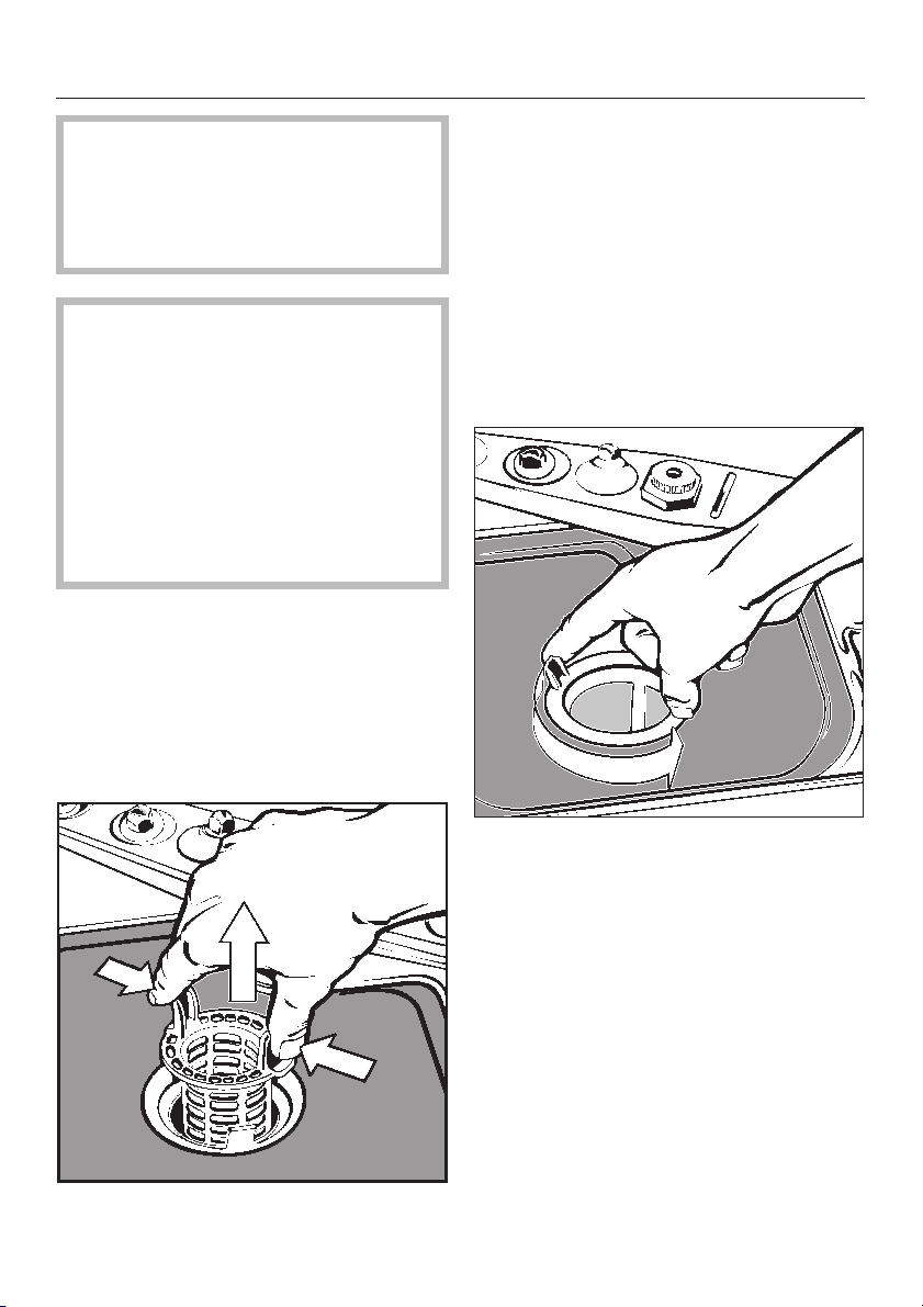
Maintaining the filter assembly
The filter assembly in the base of the
cabinet must be inspected regularly
and cleaned if necessary.
1. Cleaning the coarse filter
Remove the coarse filter.
^
Remove the fine filter from between
^
the flat and the micro-fine filters.
^
To unscrew the micro-fine filter, take
hold of the two tabs and turn twice in
a counter clockwise direction.
44
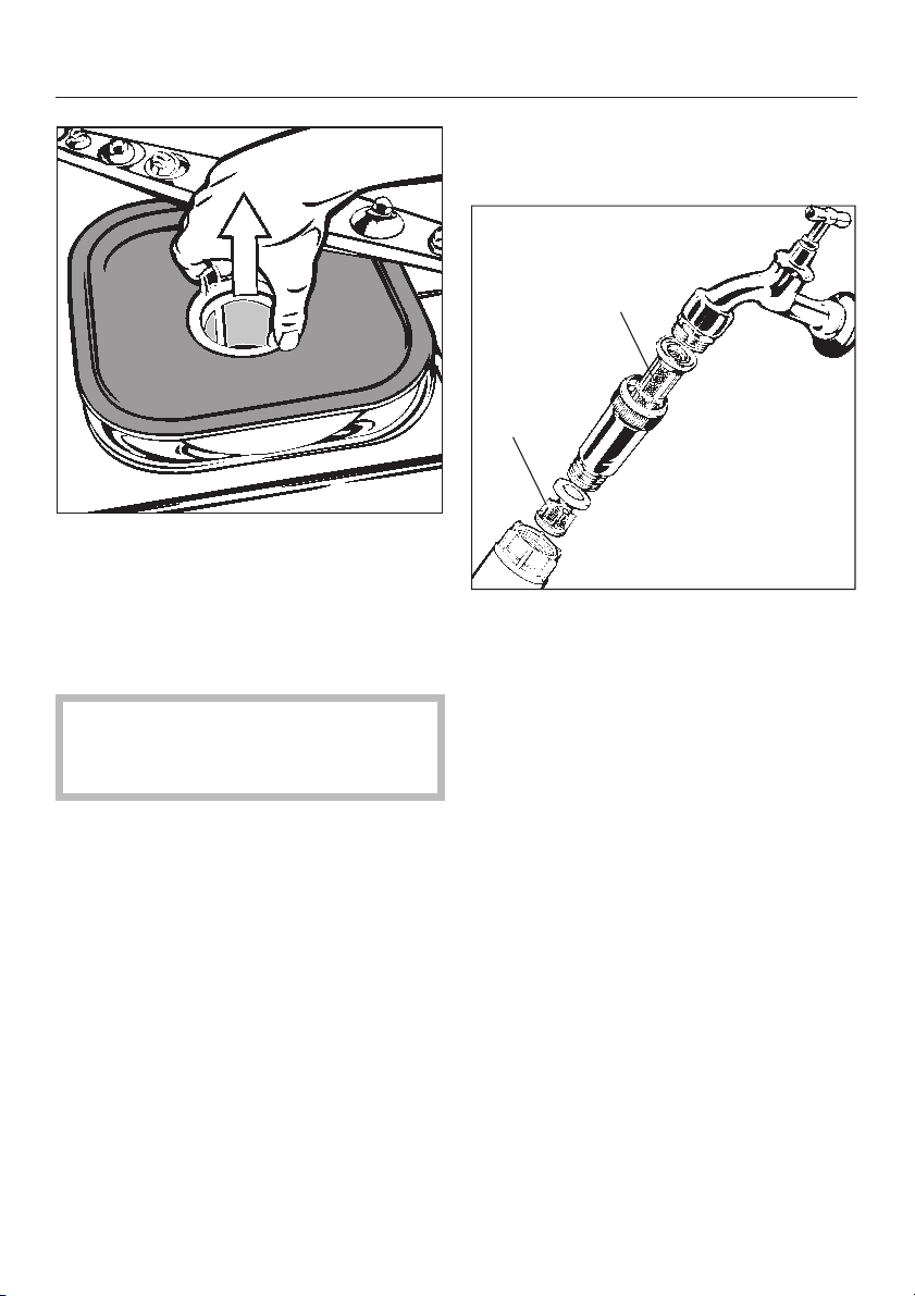
^ Pull up and remove the two filters.
^ Clean the filters.
Cleaning and care
Turn off the valves.
^
Unscrew the water inlet hoses.
^
1
2
^ The filter assembly is then replaced
in the reverse order in which it was
removed.
CAUTION: The washer/disinfector
must not be used without all filters in
place.
3. Cleaning the water inlet filters
Filters are incorporated into the stain
less steel housing located between the
supply valve and the hose.
The filters must be cleaned when dirty,
otherwise insufficient water will flow into
the wash cabinet. These filters must be
periodically inspected based on the
quality of incoming water.
-
^ Clean the large area filter (1) and the
fine filter (2) or replace if necessary.
^ After reconnection, turn on the valves
and test for leaks.
Maintaining the dispensing
system
The dispensing system should be
main-tained at regular intervals in order
to guarantee optimum safety and effi
ciency.
^
The tubes in the dispensing system
should be replaced every 2 years.
-
45
Cleaning and care
Maintaining the drying unit
To ensure thorough cleaning without
recontamination, the air filters have to
be exchanged after their life cycle
(coarse filter = 100 operating hours,
clean room filter = 500 operating
hours).
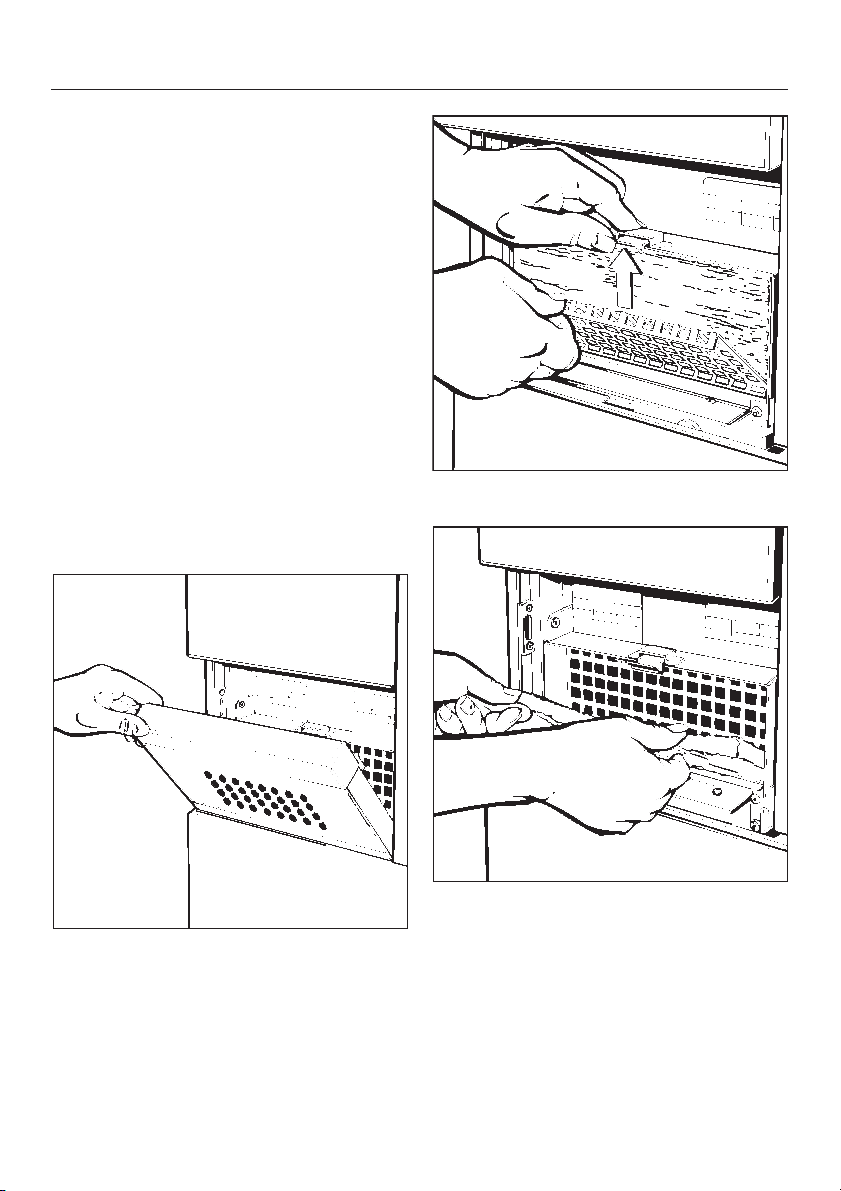
1. Changing the coarse filter
The coarse filter is located on the dry
ing unit behind the unit’s front panel,
which can be pulled out.
After 100 operating hours, this coarse
filter needs to be replaced. Please note
the total operating time that is displayed on the drying hour meter on the
sticker supplied with the filter.
^
Grip the inlet grille on the right and
left-hand side and pull up out of the
retainers. Then pull downwards and
remove.
-
^ Remove the perforated plate.
^
Change the coarse filter. The smooth
side must face toward the rear of the
drying unit.
^
Reinsert the perforated plate and
press into place at the top. The sur
rounding edge should face forward.
-
46
^
Replace the inlet grille. The grille
should audibly click into place.

2. Changing the clean room filter
The class 100 HEPA clean room filter
has a life cycle of 500 operating hours.
It needs to be replaced by specially
trained technicians. The time for the
next change is written on the sticker on
the front of the drying aggregate.
Please call technical service when the
drying hour meter reaches the time
specified.
Cleaning and care
47

Correcting minor problems
With the aid of the following explanatory
notes, minor problems can be cor
rected without contacting the Miele
Technical Service Department.
IMPORTANT: Any work on the washer/
disinfector electrical components
should only be carried out by a quali
fied person.
In the event any problems cannot be
corrected, please contact the Miele
Technical Service Department.
-
-
Warning lights
DRAIN/FILL warning light flashes
^ Check that both water intake hoses
are connected to the water supply
and that the valves are turned on.
^ Check if inlet water filters are
clogged.
^ Check the drain hoses. They should
be no higher than 3 feet (1 m) from
the base level of the washer/
disinfector. The inner diameter of the
hoses should be no less then 3/4’’
(2 cm).
The REACTIVATION light is on
Replenish the water softener. Please
^
refer to "Reactivating the water soft
ener".
The DETERGENT light is on
The liquid detergent container has to
^
be refilled.
The NEUTRALIZER light is on
The neutralizer container has to be
^
refilled.
The display shows two dashes
^ Contact the Miele Technical Service
Department.
The washer/disinfector must be reset
by a trained technician.
-
^
Check if any hoses are kinked. If so,
straighten.
^
Activate DRAIN cycle. Once DRAIN
is complete, restart processing cycle.
48

Correcting minor problems
Unsatisfactory cleaning results
Unsatisfactory cleaning results may ap
pear as drying spots, or as spots that
look like corrosion.
Presumably corrosive spots often are
bio-debris. They have the shape of dry
ing spots, blurry edges, and the color
of rust. Bio-debris may also appear on
surfaces that were not decontaminated
before processing.
Please observe:
Have the instruments been stored in
^
the washer/disinfector for more than
6 hours? If so, please run the
washer/disinfector, even partially
loaded, within 6 hours of loading.
^ Was enough detergent used? Please
check the dosage of the detergent
and adjust, if necessary. Too little as
well as too much detergent may deteriorate the cleaning results.
^ Can both spray arms rotate easily,
when the washer/disinfector is
loaded? If not, please rearrange the
goods to be cleaned in a way so that
the spray arms can rotate freely.
The water in the wash cabinet is not
heated; the cycle lasts too long
This washer/disinfector has a resettable
temperature sensor which will shut off
the heating elements in the case of
over-heating. This could be caused if
large articles cover the heating ele
ments or if the filters in the wash cabi
net are blocked.
Remove the cause of overheating.
^
Take off the service panel (see "In
^
stallation").
Press in the blue reset button on the
^
temperature sensor.
If this switch trips repeatedly, contact
the Miele Technical Service Department
before using the washer/disinfector further.
-
-
-
495051


Alteration rights reserved / 000 3201
 Loading...