

Page 1

Installation Instructions
Combi-Steam Oven
DGC 4084 XL
DGC 4086 XL
To prevent accidents
and appliance damage
read these instructions
before
installation or use.
en - US, CA
M.-Nr. 09 064 870
Page 2

Contents
IMPORTANT INSTALLATION SAFETY INSTRUCTIONS ...................3
Installation .......................................................4
Cut-out for venting the combi-steam oven ...............................6
Appliance and installation dimensions ................................8
Installation in a tall cabinet ...........................................8
Installation under a countertop ........................................9
Installation in combination with an oven ................................10
Installation in combination with ESW 408x-14 ............................11
Installation in combination with ESW 408x-14 BRWS ......................12
Installing the appliance .............................................13
Electrical connection..............................................14
2
Page 3

IMPORTANT INSTALLATION SAFETY INSTRUCTIONS
Be certain your appliance is
WARNING - Read all instructions
,
before installation or use of the
steam oven to prevent injury and
machine damage.
Installation, repair and maintenance
~
work should be performed by a Miele
authorized service technician. Work by
unqualified persons could be
dangerous.
~
properly installed and grounded by a
qualified technician. To guarantee the
electrical safety of this appliance,
continuity must exist between the
appliance and an effective grounding
system. It is imperative that this basic
safety requirement be met. If there is
any doubt, have the electrical system of
the house checked by a qualified
electrician.
Before installation make sure that
~
the voltage and frequency listed on the
data plate correspond with the
household electrical supply. This data
must correspond to prevent injury and
machine damage. Consult a qualified
electrician if in doubt.
Before installation, check the
~
appliance for visible signs of damage.
Do not install or operate a damaged
unit.
Do not operate any appliance with a
~
damaged cord or plug or if the
appliance has been damaged in any
manner.
Before installation or service,
~
disconnect the power supply to the
work area by removing the fuse,
"tripping" the circuit breaker or
switching off the power main. Ensure
that power is not restored to the
appliance during maintenance or repair
work.
Do not tamper with electrical
~
connections and components or
mechanical parts. Never open the outer
casing of the appliance.
Do not use an extension cord to
~
connect this appliance to electricity.
Extension cords do not guarantee the
required safety of the appliance, (e.g.
danger of overheating).
Make sure that the outlet is easily
~
accessible after installation of the
appliance.
This appliance must not be used in
~
a non-stationary location (e.g. on a
ship).
The appliance must be installed so
~
that the user can access all cooking
levels and containers. Otherwise you
may risk scalding or burning yourself
with hot water and food when taking
containers out of the oven.
Keep these operating instructions in
~
a safe place and pass them on to any
future user
Note to the installer:
Please leave these instructions with the
consumer of the appliance for the local
building inspectors use.
SAVE THESE
INSTRUCTIONS
3
Page 4

Installation
Miele appliances can be installed flush or proud. Discuss your installation
requirements with your architect, designer or installer.
Dimension details of the appliance front
7/8"
22*/23**
3,8"
4
111,5
7/8"
9/16"
17
1
47,5
446
1/8"
13
333
3/4"
17
451,5
15/16"
1*
1**
455,5
17
4
3/16"
-2
4
Page 5

Dimension to allow the control
panel to open and close
Installation
The area in front of the control panel
must not be blocked by anything (such
as a door handle) this would hinder the
control panel from opening and closing.
5
Page 6

Installation
Cut-out for venting the combi-steam oven
Installation in a tall cabinet
5/8"
5/8"
19
(500 mm)
1
(40 mm)
a
b
To ensure that the combi-steam oven has adequate ventilation, the following
cut-outs measuring 19
11
/16"x19/16" (500 x 40 mm) must be provided:
a in the top of the cabinet
b in the center shelf above the installation niche
If installing in combination with an oven please refer to the installation
instructions included with the oven for oven venting instructions.
6
Page 7

Installation under a countertop
5/8"
19
(500 mm)
Installation
5/8"
1
(40 mm)
b
a
To ensure that the combi-steam oven has adequate ventilation, the following
cut-outs measuring 19
a in the appliance support shelf
b in the bottom of the cabinet space below it
11
/16"x19/16" (500 x 40 mm) must be provided:
7
Page 8

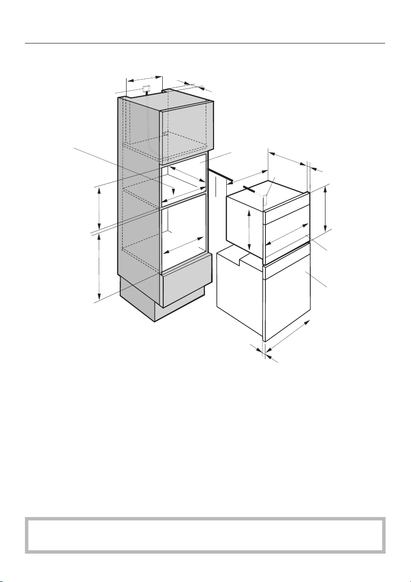
Appliance and installation dimensions
Installation in a tall cabinet
5/8"
19
(500 mm)
d
5/8"
1
(40 mm)
13/16"
- 17
5/8"
17
1/16"
22
- 22
(560 mm
- 568 mm)
(448 mm
- 452 mm)
3/8"
21
7/8"
( 555 mm)
0
e
b
5/8"
21
(549 mm)
9/16"
17
21
1/2"
(547 mm)
(22 mm*/
23 mm**)
c
(446 mm)
7/16"
23
(595 mm)
7/8"
a Combi-steam oven
b Installation niche
c Terminal block
d Outlet or junction box
This should be accessible after the appliance has been installed.
e Power cord (5 ft.)
15/16"
(455.5 mm)
17
a
* Appliances with glass front / ** Appliances with metal front
8
Page 9

Appliance and installation dimensions
Installation under a countertop
If the appliance is be installed under a cooktop, observe the installation
instructions for the cooktop and its installation height.
5/8"
19
(500 mm)
d
1/4"
- 18
1/8"
(460 mm
e
3/8"
18
21
(549 mm)
21
(547 mm)
- 465 mm)
5/8"
9/16"
17
(446 mm)
1/2"
(22 mm*/
23 mm**)
7/8"
5/8"
1
(40 mm)
21
7/8"
( 555 mm)
0
1/16"
22
(560 mm - 568 mm)
b
- 22
a Combi-steam oven
b Installation niche
c Terminal block
d Outlet or junction box
This should be accessible after the appliance has been installed.
c
7/16"
23
(595 mm)
15/16"
(455.5 mm)
17
a
e Power cord (5 ft.)
* Appliances with glass front / ** Appliances with metal front
See the "Dimension to allow the control panel to open and close" section of this
manual to ensure the countertop will not hinder the control panel from opening
and closing.
9
Page 10
Appliance and installation dimensions
)
Installation in combination with an oven
5/8"
1/16"
22
- 22
3/8"
(560 mm
- 568 mm)
13/16"
- 17
5/8"
17
7/16"
- 23
3/8"
23
d
- 452 mm)
(448 mm
- 595 mm)
(593 mm
19
(500 mm)
21
( 555 mm)
0
1/16"
22
- 22
(560 mm
- 568 mm)
1
(40 mm)
7/8"
3/8"
5/8"
e
b
5/8"
21
(549 mm)
9/16"
17
(446 mm)
21
1/2"
(547 mm)
c
7/16"
23
(595 mm)
(22 mm*
/23 mm**)
7/8"
15/16"
17
a
f
(455.5 mm)
7/8"
(22 mm*/
23 mm**
7/16"
23
(595 mm)
a Combi-steam oven
b Installation niche
c Terminal block
d Outlet or junction box
This should be accessible after the appliance has been installed.
e Power cord (5 ft.)
f Oven
* Appliances with glass front / ** Appliances with metal front
See the "Cut-out for venting the combi-steam oven" section of this manual for
more information on venting the combi-steam oven.
10
Page 11

Appliance and installation dimensions
)
Installation in combination with ESW 408x-14
5/8"
d
7/16"
- 23
3/8"
23
(593 mm-595 mm)
19
(500 mm)
(7 mm)
( 555 mm)
0
1/16"
22
- 22
(560 mm
- 568 mm)
21
3/8"
1/8"
(3 mm)
1/4"
5/8"
1
(40 mm)
7/8"
9/16"
5
b
21
(549 mm)
e
21
(547 mm)
(141 mm)
21
9/16"
(548 mm)
(22*/23**mm
5/8"
9/16"
17
(446 mm)
1/2"
21
(537 mm)
7/8"
c
23
(595 mm)
1/8"
7/16"
23
(595 mm)
7/16"
7/8"
(22 mm*
/23 mm**)
15/16"
17
(455.5 mm)
a
3/16"
5
(131 mm)
a Combi-steam oven
b Installation niche
c Terminal block
d Outlet or junction box
This should be accessible after the appliance has been installed.
e Power cord (5 ft.)
f Built-in plate warmer / built-in food warmer
* Appliances with glass front / ** Appliances with metal front
See the "Cut-out for venting the combi-steam oven" section of this manual for
more information on venting the combi-steam oven.
11
Page 12

Appliance and installation dimensions
Installation in combination with ESW 408x-14 BRWS
5/8"
19
(500 mm)
d
5/8"
1
(40 mm)
b
17
(446 mm)
21
(537 mm)
7/8"
c
23
(595 mm)
1/8"
7/16"
23
(595 mm)
21
7/8"
7/16"
- 23
3/8"
23
(593 mm-595 mm)
22
(4 mm)
( 555 mm)
0
1/16"
3/8"
- 22
(560 mm
- 568 mm)
1/8"
(3 mm)
1/8"
e
9/16"
(141 mm)
5
5/8"
21
(549 mm)
9/16"
21
1/2"
(547 mm)
21
9/16"
(548 mm)
(22*/23**mm)
a Combi-steam oven
b Installation niche
c Terminal block
d Outlet or junction box
This should be accessible after the appliance has been installed.
e Power cord (5 ft.)
f Built-in plate warmer / built-in food warmer
7/16"
7/8"
(22 mm*
/23 mm**)
15/16"
17
(455.5 mm)
a
3/16"
5
(131 mm)
* Appliances with glass front / ** Appliances with metal front
See the "Cut-out for venting the combi-steam oven" section of this manual for
more information on venting the combi-steam oven.
12
Page 13

Appliance and installation dimensions
Installing the appliance
Push the appliance into the cabinet niche and align it.
^
The device must be level, so that the steam generator can
operate properly.
Deviation from a horizontal position should not exceed 2°.
Secure the appliance by screwing the two 3.5 x 25 mm
^
wood screws (supplied) into the vertical strips on either
side of the housing.
13
Page 14
Electrical connection
CAUTION: Before installation or
,
servicing, disconnect the power
supply by either removing the fuse,
shutting off the main power or
manually "tripping" the circuit
breaker.
Installation work and repairs should
only be performed by a qualified
technician in accordance with all
applicable codes and standards.
Repairs and service by unqualified
persons could be dangerous.
Before connecting the appliance to
the power supply, make sure that
the voltage and frequency listed on
the rating label correspond with the
household electrical supply. This
data must correspond to prevent
appliance damage.
Only operate the appliance after it
has been installed.
If there is any question concerning
the electrical connection of this
appliance to your power supply,
please consult a licensed electrician
or contact Miele’s Technical Service
Department.
Power supply
Installation, repairs and other work
by unqualified persons could be
dangerous.
Be sure your electrical supply
^
matches the data plate.
The appliance is equipped witha5ft.
(1.5 m) flexible power cord encasing 3
wires ready for hardwiring to a 240 V,
20 A, 60 Hz grounded power supply.
It must be connected to a dedicated
line through the use of an approved
junction box.
A disconnection incorporated in the
fixed wiring must be provided. There
must be an all-pole contact gap of at
least 3 mm in the isolator switch
(including switch, fuses and relays).
Black wire: connect to L1 (hot)
Red wire: connect to L2 (hot)
Green wire: connect to GND (ground)
For further information, see the wiring
diagram provided with the appliance.
,
WARNING:
THIS APPLIANCE MUST BE
GROUNDED!
Installer:
Please leave these instructions with
the consumer.
14
Page 15

15
Page 16

Alteration rights reserved / 1013
INFORMATION IS SUBJECT TO CHANGE. PLEASE REFER TO OUR WEBSITE TO OBTAIN THE MOST
CURRENT PRODUCT SPECIFICATIONS, TECHNICAL & WARRANTY INFORMATION.
M.-Nr. 09 064 870 / 03
 Loading...