

Page 1
About ScanWizard 5
About ScanWizard 5
ScanWizard 5 is Microtek's scanning software developed exclusively for
Microtek scanners. ScanWizard 5's unique dual interface has features that
both novice and experienced scanner users will love.
ScanWizard 5's two interfaces are the named ScanWizard 5-Standard
Control Panel and the ScanWizard 5-Advanced Control Panel.
Learn more about the Standard Control Panel
Learn more about the Advanced Control Panel
Switching Between Standard and Advanced
file:///D|/sw56/About_ScanWizard_5.htm [8/15/03 3:49:21 PM]
Page 2

Special Feature of the Standard Control Panel
Special Feature of the Standard Control
Panel
The ScanWizard 5 - Standard Control Panel provides a simple but
straightforward control over the scanning process.
ScanWizard 5 - Standard Control Panel provides a simple and
straightforward way of navigating a scanning session that is designed for
those who wish to accomplish scanning jobs quickly and easily.
file:///D|/sw56/Who_Std.htm [8/15/03 4:45:29 PM]
Page 3

Special Feature of the Advanced Control Panel
Special Feature of the Advanced Control
Panel
The ScanWizard 5 - Advanced Control Panel provides advanced color
image enhancement tools tailored for a totally customizable scan. In this
panel, the
Advanced Image Correction (AIC) tool enables you to perform
any adjustments prior to completing the scan.
The Advanced Control Panel has four major windows consisting of the
Preview, Settings, Info and Scan Job Queue windows. The Preview
and Settings windows appear automatically whenever ScanWizard 5 is
activated.
file:///D|/sw56/Who_adv.htm [8/15/03 4:45:42 PM]
Page 4
Switching Between Standard and Advanced
Switching Between Standard and
Advanced
To switch between Standard and Advanced Control Panels, click on the
Switch icon . Within a few seconds, the current program exits and
switches to the other control panel mode.
file:///D|/sw56/Switching_std_adv.htm [8/15/03 4:45:49 PM]
Page 5
Quick Start-up
Quick Start-up
The Scanning sequence is done in six easy steps.
Step 1.
Install Microtek ScanWizard 5
Step 2.
Position your original material
Step 3.
Launch ScanWizard 5
Step 4.
Scan your material
Step 5.
Save your scan material
Step 6.
Exit ScanWizard 5
Step 1. Install Microtek ScanWizard 5
Install the ScanWizard 5 scanner driver (included in your Microtek CDROM) as instructed in a separate document that came with your scanner
package.
For ScanWizard 5 to work properly after installation, the correct scanner
model should be properly connected to your computer beforehand and
must be "powered on" before ScanWizard 5 is launched.
Step 2. Position your original material
Place your material face down on the scanner bed.
Step 3. Launch ScanWizard 5
A. Launching ScanWizard 5 as a stand-alone program
Double-click the ScanWizard 5 icon
on your desktop; or
B. Launching from an image-editing application
file:///D|/sw56/Quick_Start-up.htm (1 of 2) [8/15/03 3:50:43 PM]
Page 6

Quick Start-up
Launch your image-editing software (such as Adobe Photoshop Elements)
from its folder, then acquire ScanWizard 5 from the software.
Step 4. Scan your material
As soon as you launch ScanWizard 5, it will automatically detect,
configure, scan, and perform a fast preview of the scan material and
displays it in the preview area of the panel.
To set and make adjustments to the image, use the Tool buttons in the
Toolbar (Original, Scan Type, Purpose, Scale Output, or Adjust).
Step 5. Save your scan material
Click the Scan to button to scan the image. The image is then scanned
and saved to a file. Aside from saving, you may also deliver the scanned
image to an image-editing program, print as a copy on your printer, or
attach the image to an e-mail application.
Step 6. Exit ScanWizard 5
Choose Quit ScanWizard 5 from the "ScanWizard 5" System Menu bar.
file:///D|/sw56/Quick_Start-up.htm (2 of 2) [8/15/03 3:50:43 PM]
Page 7

sw5osx_system menu
ScanWizard 5 System Menu bar
ScanWizard 5 menu
This ScanWizard 5 System menu bar lets you exit ScanWizard 5, and
shows program version and copyright information.
File menu
The File menu lets you set document attributes for your printer.
Help menu
The Help menu lets you access on-line help for ScanWizard 5, and gives
you information on the ScanWizard 5 scanning software.
file:///D|/sw56/sw5_system.htm [8/15/03 3:51:28 PM]
Page 8
Standard Control Panel
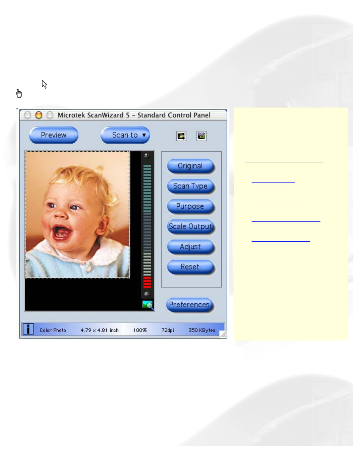
Standard Control Panel
The ScanWizard 5 - Standard Control Panel offers a simple and easy way to complete
a scanning session.
To view information about the functions of the Standard Control Panel, position the
cursor
over any button, icon, or bar on the panel, and then click the grabber pointer
to activate the related pop-up information dialog box.
Select the topic you wish
to view from the links
below for more specific
explanations:
The Preview window
-
Scan frame
-
Toolbar buttons
-
Final scan buttons
-
Control buttons
file:///D|/sw56/std.htm [8/15/03 3:52:39 PM]
Page 9
Preview window
Standard Control Panel
Preview window
By default, ScanWizard 5 - Standard Control Panel automatically
detects and creates a preview image of your original material in the preview
window when you first launch the program.
If you have disabled the auto-preview function under the "Preferences"
dialog box, you will need to manually click the Preview button to prescan
and preview your material.
Scan frame Plotting, Moving, Resizing
Toolbar commands Original, Scan Type, Purpose, Scale Output, Adjust, Reset,
Preferences
Final scan buttons Scan To, Copy, E-mail, OCR, To Web
Control buttons Pan tool, Zoom controls, i [Info], Arrow, Switch, Scanner info, Minimize
Scan frame
A Scan frame is a floating dotted-line border around a selected image.
Plotting
Moving
Resizing
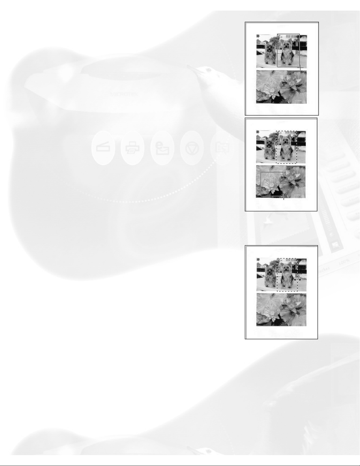
Plotting
file:///D|/sw56/std_Preview_window_detail.htm (1 of 9) [12/16/03 11:54:52 PM]
Page 10
Preview window
To plot a scan frame, move the cursor to any
corner of your intended scan frame. When the
crosshair pointer appears, drag diagonally until
you have the desired image selection enclosed in
a frame, and then release the mouse. Your
actual scan frame border now turns into
cascading or dotted lines.
To create a new scan frame over an existing one
or to create a new scan frame in another
location of the same preview image, follow the
steps in plotting a scan frame. When you release
the mouse, however, the previous scan frame
will be discarded.
Resizing
Point at any border of the scan frame until a twoway arrow pointer appears. Drag horizontally or
vertically until you have achieved the desired
width and height adjustments.
Moving
file:///D|/sw56/std_Preview_window_detail.htm (2 of 9) [12/16/03 11:54:52 PM]
Page 11
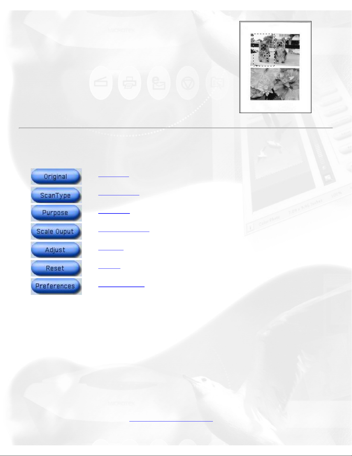
Preview window
If you wish to use an existing scan frame
dimension to select another area of the scan
image, simply move the existing scan frame over
to the new area by pointing anywhere within the
existing scan frame. When the four-way arrow
pointer appears, drag the scan frame to the
target area.
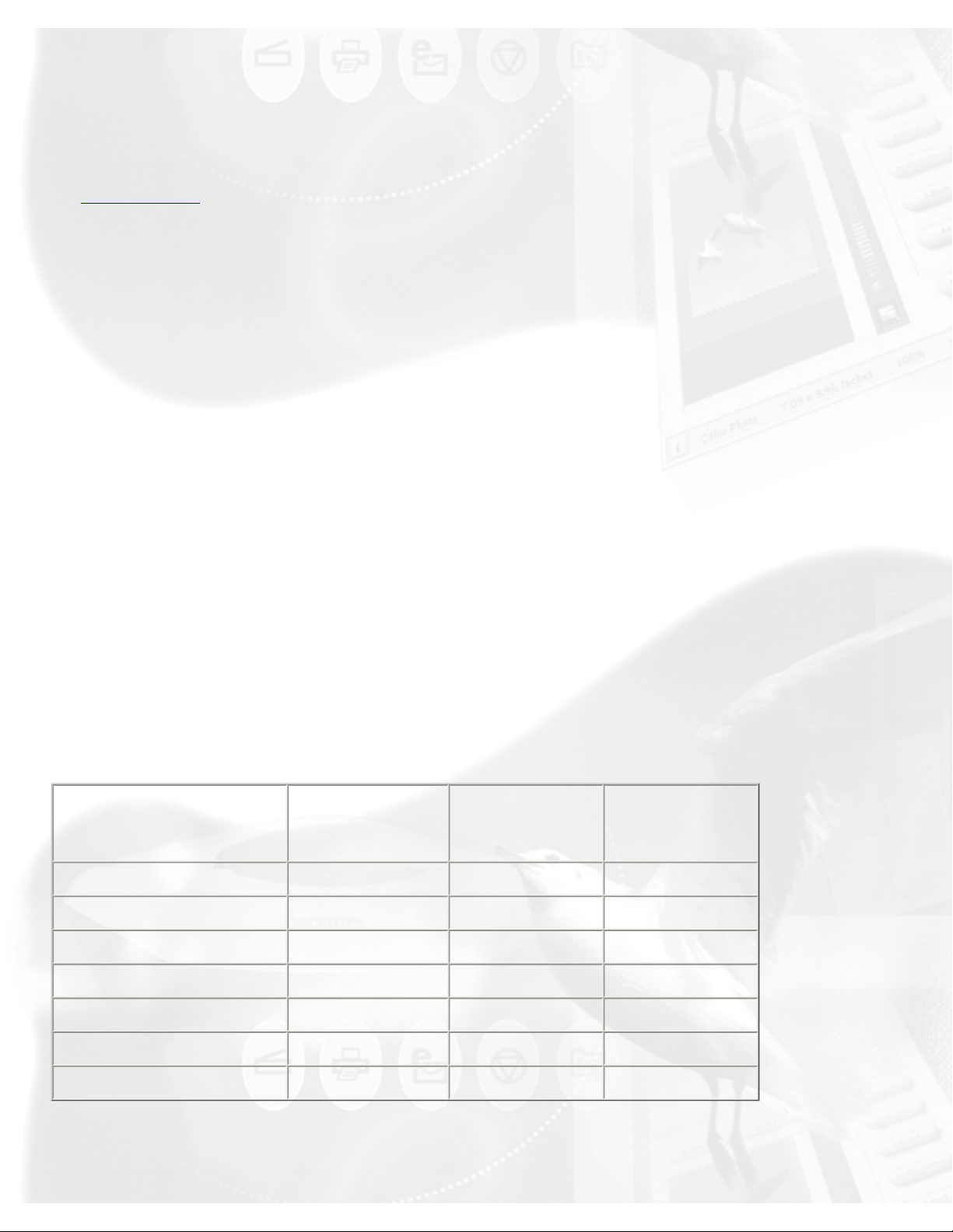
Toolbar commands
Original
Scan Type
Purpose
Scale Output
Adjust
Reset
Preferences
The Standard Control Panel's Toolbar commands are designed for selecting
your scan-setting requirements. There is no prescribed order or sequence
required for using the Toolbar commands in defining various aspects of your
image.
Original button
The Original button lets you select the type of material to be scanned.
ScanWizard 5 - Standard Control Panel determines the best scanning
parameters to automatically configure your original material.
Options for selecting the type of scan material under the Original button
include: Photo, Text Document, Illustration, Printed Material, Film, etc.
file:///D|/sw56/std_Preview_window_detail.htm (3 of 9) [12/16/03 11:54:52 PM]
Page 12
Preview window
Scan Type button
The Scan Type button allows you to select the image output to which the
original scan material will be converted. The options for choosing the output
image type are: True Color, Web Color, Gray, B&W, or JPEG.
Purpose button
The Purpose button displays a menu for selecting the intended usage of
the output image resolution. Different image resolution values are provided
for different output applications. The higher the resolution, the bigger the
memory size required for uploading and downloading images.
This is your button for defining image output resolution to match the target
application (On-screen Viewing, Normal Screen, Ink-Jet Printing, and
Laser).
Select from the menu the particular setting that will best match the
intended device application for your output image. Different types of
originals may have different predefined resolution values as shown on the
table below.
If none of the predefined resolution matches your need, you may define
your own resolution by selecting "Custom" and then enter your own
resolution value in the Edit box provided at the bottom of the menu.
Remember that the higher the resolution, the larger the file size will be.
Text
Doc./Photo
+/- Film Graphic
and
Magazine
Normal Screen
72 72 72
Fine Screen
96 96 96
Ink Jet Printer
300 200 300
300 Laser Printer
300 100 300
600 Laser Printer
600 150 300
Fax
200 200 200
OCR
300 300 300
Scale Output button
file:///D|/sw56/std_Preview_window_detail.htm (4 of 9) [12/16/03 11:54:52 PM]
Page 13
Preview window
This button lets you select image output resolution in terms of size/aspect
ratio. (50%, 75%, 100%, 150%, or 200 %).
Adjust button
This button is your basic image enhancement tool for modifying or
enhancing image(s) at the scanning stage.
It is suggested that you adjust the Brightness, Contrast, Sharpness, Color,
and Saturation of the preview image to enhance the output image. Click on
the Adjust button, and the Standard Control Panel image correction tool will
display. Adjust the image appearance by dragging the slider of each tool.
Observe the changes from the preview image every time you move each
button.
Reset button
This button will cancel your defined choices or revert to the default settings.
Preferences button
This button will give you access to the "Preferences" dialog box to set up
the scan function and allow you to repaint or customize the appearance of
your Standard Control Panel.
The Preferences setup dialog box provides options on how you would like
ScanWizard 5 - Standard Control Panel to handle your scan material when
the program is launched.
To redefine the Preferences setup, click on the Preferences button. From the
Preferences dialog box, select and choose your preferred options.
Automatically previews scan bed when launching ScanWizard 5
If checked, a reflective original overview will be carried out when
ScanWizard 5 is launched. If unchecked, no preview is carried out.
Auto-detect image type and find edges of photo or document
If checked, the scanner detects the image type when a preview is in
progress and performs auto-cropping of the frame for reflective originals. If
unchecked, the image type can be chosen by the user, and a scan frame
file:///D|/sw56/std_Preview_window_detail.htm (5 of 9) [12/16/03 11:54:52 PM]
Page 14
Preview window
can be set manually for cropping.
Auto image enhancement
If the "Auto Image Enhancement" option is checked, the resulting image
appears sharper and brighter and with more saturated colors.
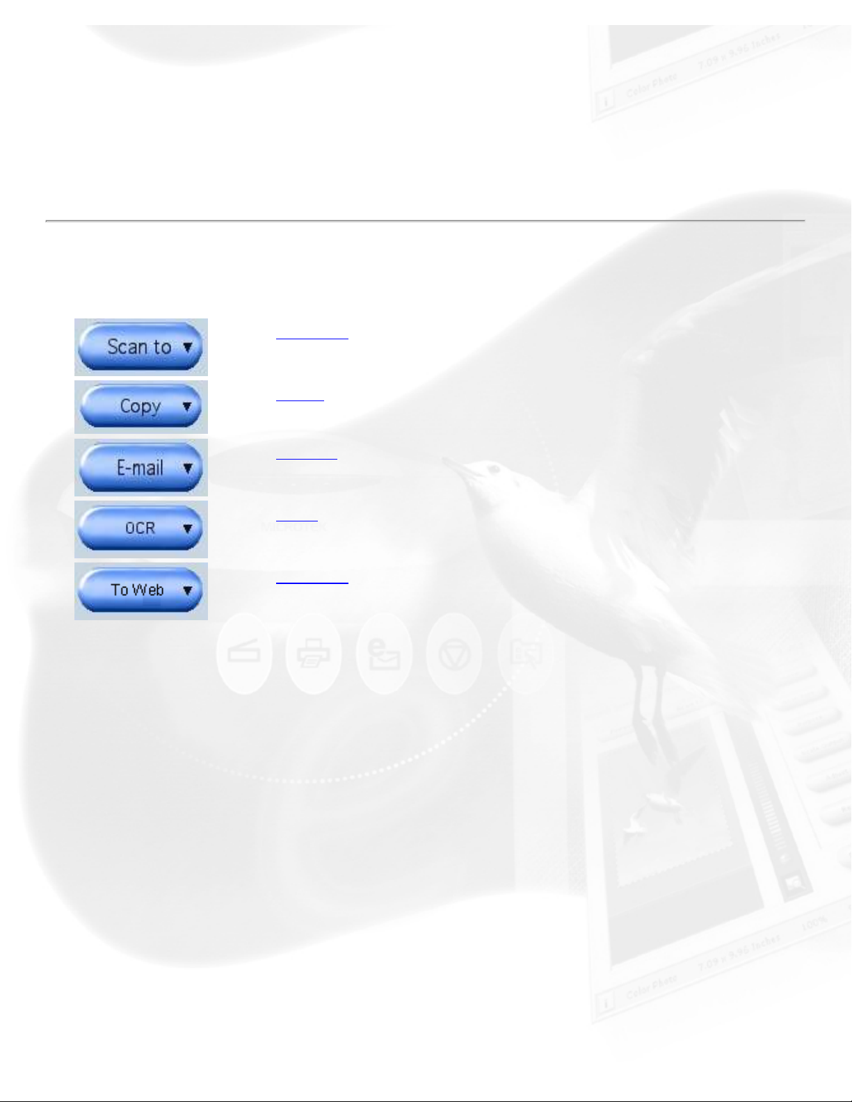
Final scan buttons
Scan to
Copy
E-mail
OCR
To Web
Scan to button
When ScanWizard 5 - Standard Control Panel is launched as a stand-alone
program, this is the default setting. This is also the default button on
scanners with the "Go" button feature.
Copy button
Point the cursor on the Scan To button, then click and hold the button for a
moment. Select Copy from the drop-down menu.
When the Print dialog box appears, select your default printer or any
alternative printer from the options, then specify the number of copies to be
made. When you are ready to print, click Print to create a copy of the
scanned material directly on your default printer.
The function of the Copy button is similar to the E-mail button.
file:///D|/sw56/std_Preview_window_detail.htm (6 of 9) [12/16/03 11:54:52 PM]
Page 15

Preview window
E-mail button
ScanWizard 5 automatically attaches the scanned image to your E-mail
message.
Point the cursor on the "Scan to" button for a moment, then click and hold
the button. Select E-mail from the drop-down menu.
The Save As dialog box appears and prompts you to save the file to your
folder and key in a file name. It is recommended that you use either JPEG
or PICT as the file format.
Make sure that the check box "Send image(s) to application after saving"
has been selected/checked.
Make sure your preferred E-mail application is selected from the listed
options.
Click Save to launch your E-mail editor with the attached image, then start
typing your message and hit the Send button.
OCR button
Point the cursor on the Scan or Scan to button, then click and hold the
button for a moment. Select OCR from the drop-down menu.
When the Save As dialog box appears, key in a file name, then select .rtf,
.txt, .xls, .htm, and pdf as the export file format.
Make sure that the check box "Send document to application after saving"
has been selected/checked. Now, choose the Word processing application
from the options, and then click Save. The saved file can now be opened
from your chosen application, and is ready to be edited.
To Web button
Point the cursor on the Scan or Scan to button, then click and hold the
button for a moment. Select To Web from the drop-down menu.
ScanWizard 5 will check if the image size does not exceed the allowed file
size. When the "Microtek ScanWizard 5 - Scan to Web" dialog box appears,
save the file in your preferred folder, key in a file name, specify the file
file:///D|/sw56/std_Preview_window_detail.htm (7 of 9) [12/16/03 11:54:52 PM]
Page 16
Preview window
type, and choose the website address from the options given.
The scanned image will automatically be uploaded directly to the
default/chosen website.
Control buttons
Pan tool
/
Zoom controls
i [Info]
Arrow
Switch
Scanner info
Minimize
Pan tool
Pans or moves around a magnified preview area
Zoom controls
(+) Zoom in button to magnify the preview image
(-) Zoom out button to shrink the preview image
i [Info]
The Info icon or status bar will show a summary of current configuration
settings on the current image and also becomes a progress bar during
scanning. Click this icon for more detailed configuration info.
Arrow
This is your button for resizing the preview window. Simply drag the Arrow
icon (located at the bottom right corner of the panel) to adjust the size of
the window.
Switch
file:///D|/sw56/std_Preview_window_detail.htm (8 of 9) [12/16/03 11:54:52 PM]
Page 17

Preview window
This icon enables you to change/switch to the Advanced Control Panel and
the Standard Control Panel, respectively.
Scanner info
Click the Scanner info icon to access the "Scanner Control and Scanner
Information" options menu.
ScanWizard 5 is constantly in touch with your scanner, monitoring scanner
availability and serviceability, as well as its make and mode. To see how
your scanner is performing, click this icon from the title bar.
Minimize
To minimize the Preview window, click on the Minimize icon located on the
top left corner of the Preview window.
file:///D|/sw56/std_Preview_window_detail.htm (9 of 9) [12/16/03 11:54:52 PM]
Page 18
Advanced Control Panel
Advanced Control Panel
The ScanWizard 5 - Advanced Control Panel provides users the power to specify,
correct, and improve the image at the scanning stage.
To learn more, click on any of these four windows.
file:///D|/sw56/adv.htm (1 of 2) [12/17/03 12:37:46 AM]
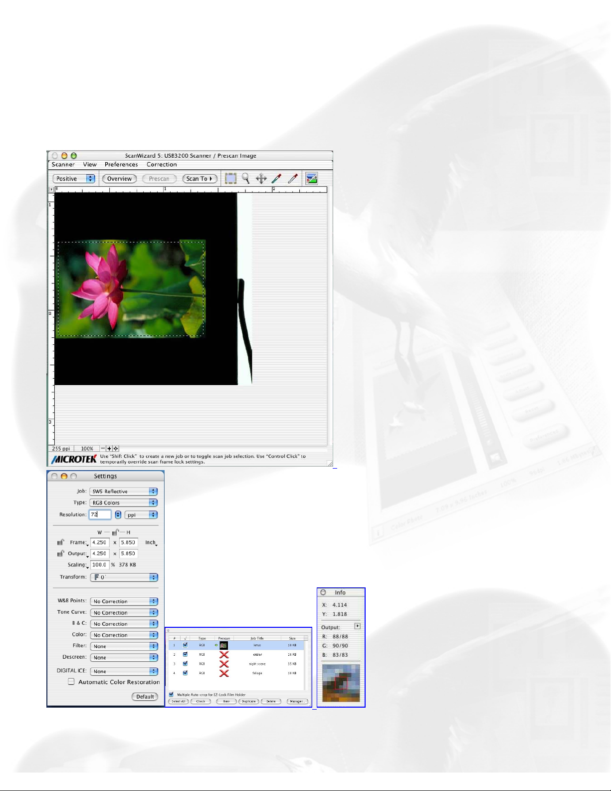
Page 19

Preview window
Advanced Control Panel
Preview window
The Preview window is the main window of the four windows. The Preview
window is where your image appears after you click on the Overview or
Prescan button.
Preview area Preview image information
Handy buttons Preview image resolution, Zoom scale, Zoom-in, Zoom-out, Flasher for
High and Low Value Markers
Menu bar Scanner, View, Preferences, Correction
Scan Material Reflective, Positive, Negative
Overview, Prescan, Scan to/Copy/E-mail/OCR/To Web
Control buttons Unit of Measurement/Ruler, Switch, Minimize, Maximize
Toolbar Scan Frame, Zoom, Pan, Pickers
Preview area
The preview area is where the overview or prescan image appears. You
can increase the size of the preview area to see more detail in your image.
Take note of the following:
● When you perform an overview, the overview image size is
determined by the current preview area dimension. The bigger the
preview area, the higher the preview resolution.
● When you perform a prescan, the prescan image details is
file:///D|/sw56/adv_Preview_window_detail.htm (1 of 11) [8/15/03 3:59:29 PM]
Page 20
Preview window
determined by the settings in the Prescan Setup dialog box.
● Drag the bottom right corner of the Advanced Control Panel to adjust
the size of the Preview window.
● The status bar provides helpful tips when you click on any button on
the panel.
For details on how to change the actual preview area of the scan bed, refer
to the Overview Setup command in the Preferences menu section.
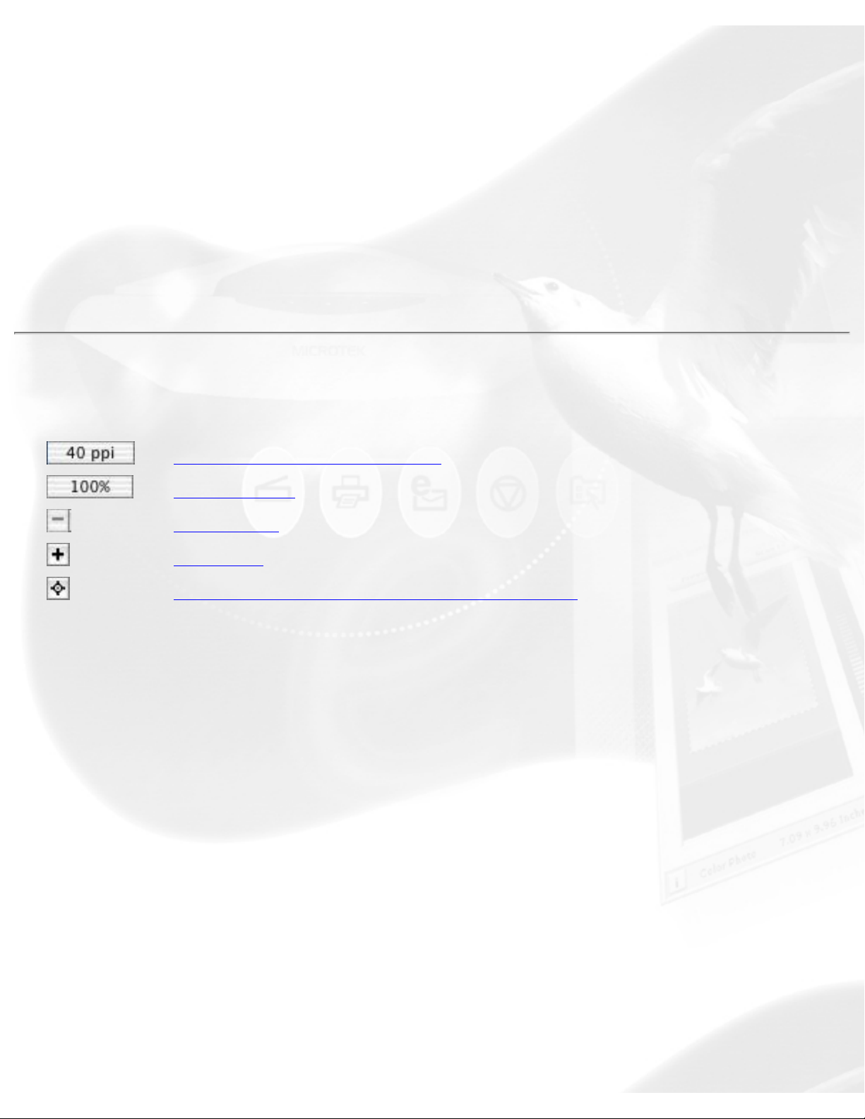
Handy buttons
Preview image resolution
Zoom scale
Zoom-out
Zoom-in
Flash for High and Low value markers
Preview image resolution
This shows the image resolution for the Overview or Prescan image. The
preview image resolution will change, according to the size of the preview
window and the amount of available memory. To resize preview window,
drag any side or corner of the window.
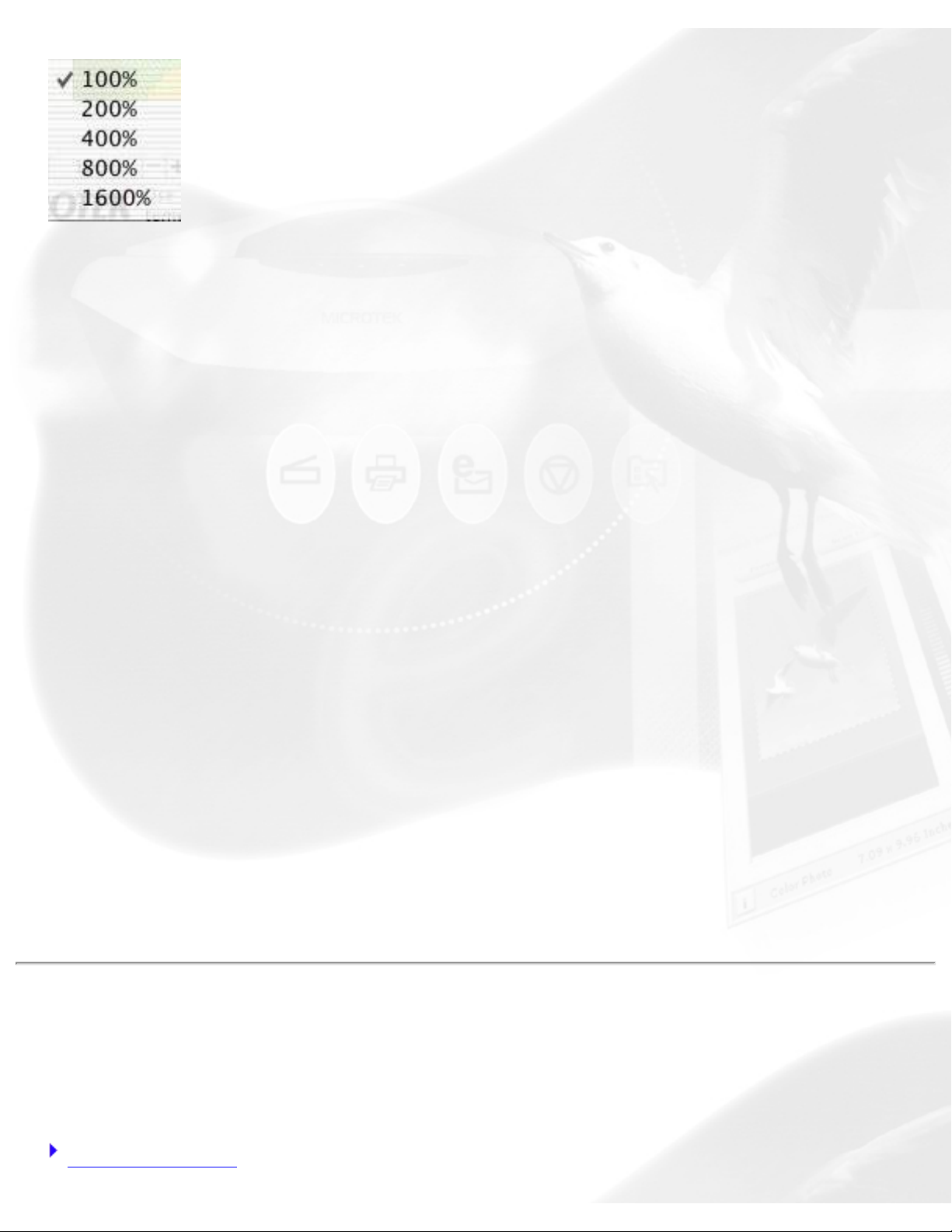
Zoom scale
This shows the zoom factor, or how many times the image has been
magnified using the Zoom tool or the Zoom in / Zoom out icons to the
right of the Zoom scale. You may select the exact Zoom scale from here.
The magnification factor in both Zoom scale and the Zoom tool is by a
factor of 2. Thus, the magnification levels increase from 100% to 200%, to
400%, 800% to 1600%.
file:///D|/sw56/adv_Preview_window_detail.htm (2 of 11) [8/15/03 3:59:29 PM]
Page 21
Preview window
To use the Zoom scale:
Click on the Zoom scale from the bottom of Preview window. From the
drop-down menu that appears, select your zoom or magnification level.
Zoom-out
This lets you reduce a zoomed-in or magnified image one level down with
each click, up to the minimum 100% view.
Zoom-in
This lets you magnify or enlarge the image one level up with each time
you click, up to the maximum 1600% view.
Flasher for High and Low Value Markers
When the overview or prescan image is displayed, the High Value and Low
Value Markers are shown. If the two markers cannot be visually detected
with ease (depending on how your image may obscure the markers),
clicking the flasher activates the markers to flash a few times for easier
detection, allowing their locations on the overview or prescan image to be
seen.
Menu bar
The menu bar includes the different menus for setting up the scanner.
Scanner menu To view the status and technical information about your scanner
file:///D|/sw56/adv_Preview_window_detail.htm (3 of 11) [8/15/03 3:59:29 PM]
Page 22
Preview window
View menu To modify the ScanWizard 5 windows
Preferences menu To customize how the image is processed
Correction menu Contains the Advanced Image Correction items
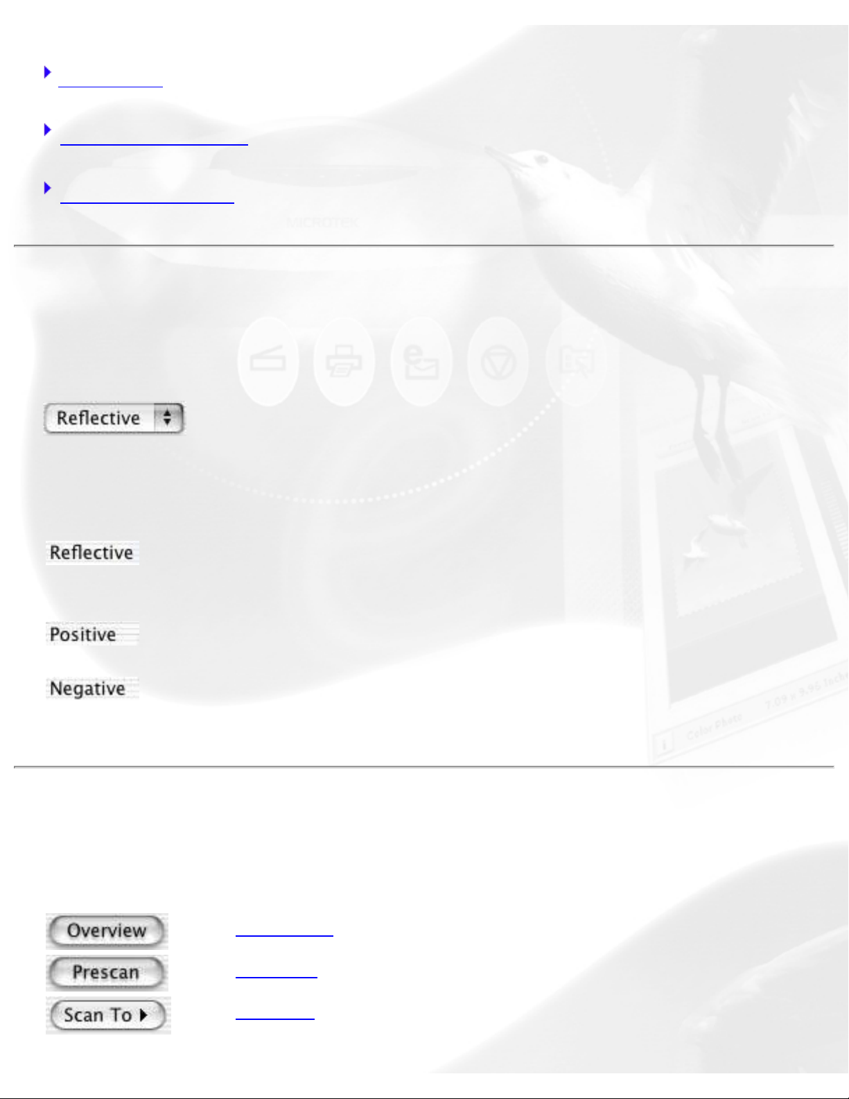
Scan Material
Access the Scan Material by using the Scan Material menu.
The Scan Material option changes, depending on whether your scan
material is reflective, positive, or negative.
Select this option if you are scanning
reflective materials (such as photos or
printed material).
Select this option if you are scanning a
positive transparency or filmstrip.
Select this option if you are scanning a
negative transparency or filmstrip.
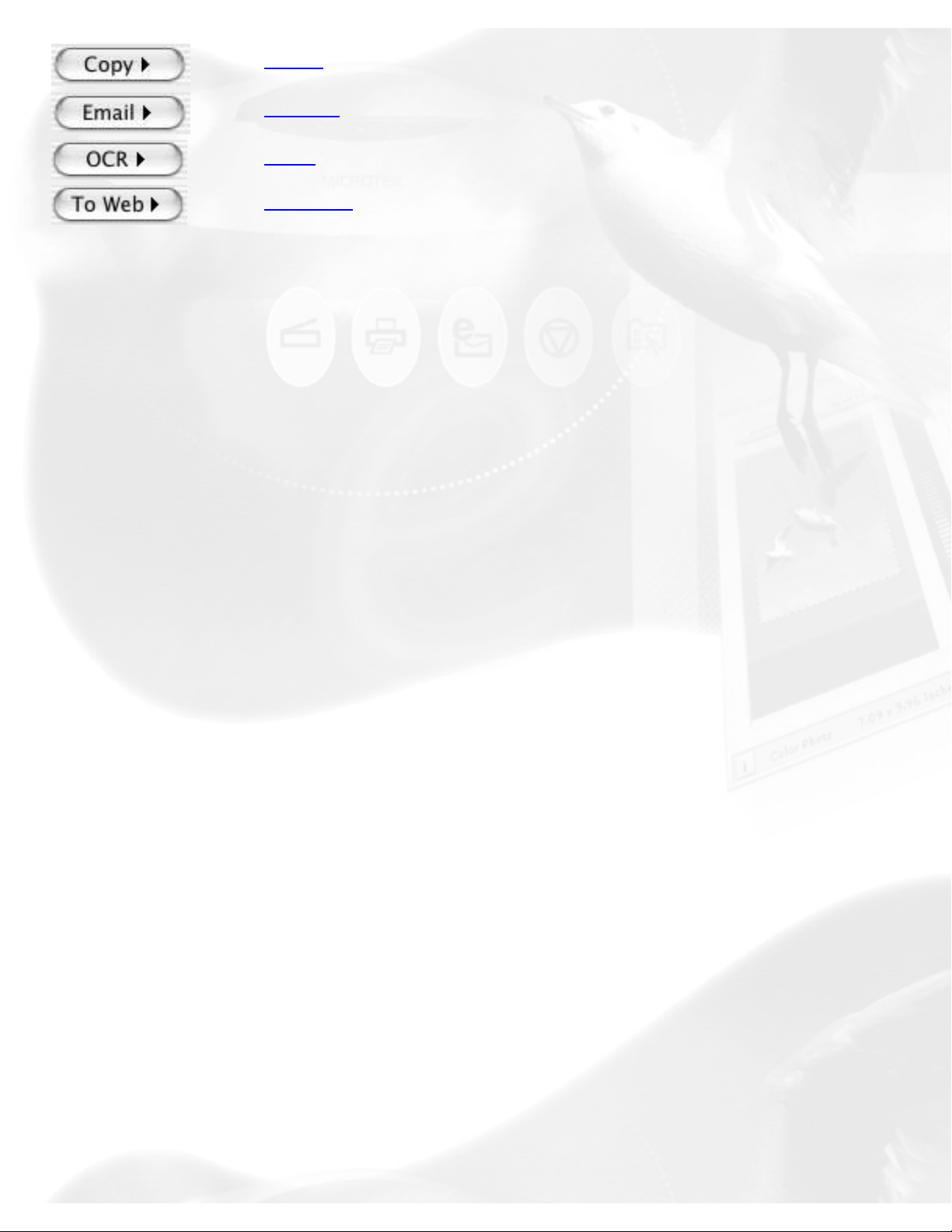
Overview, Prescan, Scan
to/Copy/Email/OCR/To Web
Overview
Prescan
Scan to
file:///D|/sw56/adv_Preview_window_detail.htm (4 of 11) [8/15/03 3:59:29 PM]
Page 23
Preview window
Copy
E-mail
OCR
To Web
Overview button
The Overview button previews the image on the scan bed. By default, the
entire scan bed is previewed when you click the Overview button. To
change the area to be previewed, specify the dimensions in the Overview
Setup command (in the Preferences menu).
Prescan button
The Prescan button previews in high resolution the area selected by the
scan frame tool. Multiple prescans can be done if you have several
selected scan jobs, and the prescans are done one after another in the
order that they are listed in the Scan Job Queue window. Options
governing the prescan function can be found in the Prescan Setup
command in the Preferences menu.
To obtain multiple prescan images:
1. Define your scan jobs in the Scan Job Queue window (see the Scan
Job Queue window section for more details).
2. To select multiple scan jobs, press the Shift key and click on the jobs
to be selected in the Scan Job Queue or Preview window.
3. Click the Prescan button in the Preview window. Multiple prescans are
created in the process, corresponding to the number of scan jobs
defined, and you can then switch among the various prescan images.
Scan to button
When ScanWizard 5 - Standard Control Panel is launched, this is the
file:///D|/sw56/adv_Preview_window_detail.htm (5 of 11) [8/15/03 3:59:29 PM]
Page 24

Preview window
default setting. This is also the default button on scanners with the "Go"
button feature.
Copy button
Point the cursor on the Scan To button then click and hold the button for a
moment. Select Copy from the drop-down menu.
When the Copy dialog box appears, select your default printer or any
alternative printer from the options, then specify the number of copies to
be made. When you are ready to print, click Print to create a copy of the
scanned material directly to your default printer.
The function of the Copy button is similar to the E-mail button, but the
image goes directly to your default or selected printer.
E-mail button
Point the cursor on the Scan To button, then click and hold the button for a
moment. Select E-mail from the drop-down menu.
ScanWizard 5 automatically attaches the scanned image to your E-mail
message.
The Save As dialog box appears and prompts you to save the file to your
preferred folder and key in a file name. It is recommended that you use
either JPEG or PICT as the file format.
Make sure that the check box "Send to application after saving" has been
selected/checked.
Make sure your preferred E-mail application is selected from the listed
options.
Click Save to launch your E-mail editor with the attached image, then type
your message and hit the Send button.
OCR button
file:///D|/sw56/adv_Preview_window_detail.htm (6 of 11) [8/15/03 3:59:29 PM]
Page 25
Preview window
Point the cursor on the Scan or Scan To button then click and hold the
button for a moment. Select OCR from the drop-down menu.
When the Save As dialog box appears, key in a file name, then select .rtf,
.txt, xls, .htm, or .pdf as the export file format.
Make sure that the check box "Send document to application after saving"
has been selected/checked. Then choose the word processing application
from the options, and click Save. The saved file can now be opened from
your chosen application and is ready to be edited.
To Web button
Point the cursor on the Scan or Scan to button then click and hold the
button for a moment. Select To Web from the drop-down menu.
ScanWizard 5 will check if the image size does not exceed the allowed file
size. When the "Microtek ScanWizard 5 - Scan to Web" dialog box appears,
save the file in your preferred folder, key in a file name, file type, and
choose the website address from the options given. The scanned image
will automatically be uploaded directly to the default/chosen website.
Note: If you have not created an account with iMira.com -- you can do so
now by clicking the "Create a new account for photo Sharing" button from
the same dialog box, to enable access and speed up the process of
uploading images directly to this website.
Control buttons
The Control buttons generate a specific action from the scanning software
which includes: Rulers, Unit of Measurement, Switch, Maximize, and
Minimize.
Rulers, Unit of Measurement
Switch
file:///D|/sw56/adv_Preview_window_detail.htm (7 of 11) [8/15/03 3:59:29 PM]
Page 26
Preview window
Maximize
Minimize
Rulers, Unit of Measurement
The rulers on both sides of the preview window assist you in
measurement or in checking the alignment of your image.
The unit of measurement in the ruler can be selected in two ways: in the
Image Dimension controls located in the Settings window, or by clicking on
the ruler unit button at the 0,0 point of the rulers in the Preview window.
Depending on your selection, the rulers can mark off measurement in
these units: inch, centimeter, millimeter, point, and pixel. The pixel option
is dimmed if the selected resolution unit is lpi, and vice versa.
To select the unit of measurement for the rulers:
Click on the unit box in the Settings window, or click on the ruler unit
button
at the 0,0 point of the rulers in the Preview window. When the
submenu appears, select the unit of measurement.
Switch icon
This icon enables you to change/switch to the Advanced Control Panel and
the Standard Control Panel, respectively.
Maximize
To maximize the Preview window, click on the Maximize icon located on
the top left corner of the Preview window title bar.
Minimize
To minimize the Preview window, click on the Minimize icon located on
the top left corner of the Preview window title bar.
file:///D|/sw56/adv_Preview_window_detail.htm (8 of 11) [8/15/03 3:59:29 PM]
Page 27
Preview window
Toolbar
The Toolbar simplifies the performance of certain tasks. The buttons in the
Toolbar consist of: Scan Frame, Zoom, Pan, and Pickers.
Scan Frame
Zoom
Pan
White Picker
Black Picker
Scan Frame tool
The Scan Frame lets you create a single scan frame or multiple scan
frames in the preview image, which is the active area on which controls
and commands can be applied.
The Scan Frame can also be used to create batch scans. The current scan
frame is indicated by a marquee (cascading border). The current scan
frame can be more easily distinguished if you turn on the Smoked Glass
Background command (in the Preferences menu).
Zoom tool
The Zoom tool enlarges your view of the preview image, allowing you to
set the scan frame with greater precision if you need to. Only your view of
the preview image is changed; the actual output size of the image remains
unaffected.
Each click of the Zoom tool magnifies or reduces image view by a factor of
2. Thus, the magnification levels increase from 100% to 200%, to 400%,
to 800%, and to the maximum of 1600%.
Note: If the Info window is open, the zoom level will be indicated. This
file:///D|/sw56/adv_Preview_window_detail.htm (9 of 11) [8/15/03 3:59:29 PM]
Page 28
Preview window
means you can also zoom in by selecting the appropriate zoom level in the
Info window.
Pan tool
The Pan tool lets you scroll through a preview image, allowing you to
move parts of the image into view.
The Pan tool can be used for zoomed-in images (enlarged through the
Zoom tool), or images not completely displayed within the frame of the
preview window (for instance, if your preview image is 7 inches wide and
you resized the width of your overview/preview window to only 3 inches).
White / Black Point Picker tool
The Picker tools allow you to sample color from a particular area in an
image, and are also useful for designating shadow or highlight point.
The White Point Picker ( ) lets you define the whitest reference point in
the preview image. Once you have picked the whitest point, excessive
white points are clipped off.
The Black Point Picker( ) lets you define the darkest reference point in
the preview image. Once you have picked the darkest point, excessive
black points are clipped off.
With the Picker tools, you can determine the color values for any pixel in
an image. When you click on the White/Black Picker and pan over a pixel,
the value for that pixel is displayed in the Info window, based on the
sample size selected in the Info window. Pixel value information is useful
especially when you are making color adjustments based on color value.
To change the sample size of the Picker tool:
1. Open the Info window by choosing the Show Info Window command
in the View menu.
2. Click on the Color Meter Options button located to the right of the
RGB values in the Info window.
file:///D|/sw56/adv_Preview_window_detail.htm (10 of 11) [8/15/03 3:59:29 PM]
Page 29

Preview window
3. Choose your options.
Select the sample size options from the drop-down list. For instance, the 1
by 1 option will display the value of one pixel — the one in the middle of
the Color Output Meter. The 3 X 3 option reads the average value of a 3pixel by 3-pixel area.
To display color information for a pixel or an averaged area:
1. Click on the Picker tool.
2. As you pass over a point in the image, observe the Info window —
the RGB values will be displayed in the Color Output Meter. These
values are based on the sample size you selected.
file:///D|/sw56/adv_Preview_window_detail.htm (11 of 11) [8/15/03 3:59:29 PM]
Page 30

Settings window
Advanced Control Panel
Settings window
The Settings window contains the parameters for outputting your
scanned image for the current scan job and includes the advanced image
correction tools of the program.
Job
Type
Resolution
Resolution Unit
Scan Frame settings
Output settings
Scaling
Scan Frame options (Locks)
Transform
Unit of Measurement
Job
This shows the current scan job as indicated by the Scan Job Queue
window and corresponds with the selected image in the Preview window.
Type
file:///D|/sw56/Settings_window_detail.htm (1 of 9) [8/15/03 3:59:58 PM]
Page 31

Settings window
ScanWizard 5 allows direct scanning in the following color spaces described
below. The desired color space in ScanWizard 5 can be selected in the
Type box in the Settings window.
RGB Colors
RGB images use three colors (Red, Green, and Blue) to reproduce up to
68.7 billion colors. Because scanners and monitors are RGB devices, the
RGB color space is the most commonly used space for capturing and
displaying images. ScanWizard 5 offers standard RGB and 48-bit RGB color
selection, with the 48-bit option available for the Microtek professional prepress scanners.
Gray Scale
Grayscale images use shades of gray to simulate gradations of color or
tonal values, and contain 8 bits per pixel. The Grayscale 16-bit option is
provided in ScanWizard 5 for professional pre-press scanners.
Web/Internet Colors
This mode is useful for displaying images on the Web or Internet. Output
for the Web/Internet color mode in ScanWizard 5 is 8-bit, 256 indexed
color images.
Line Art
Line Art images are made up of one bit of color (black or white) per pixel.
Few editing options are available in this mode, but this mode is useful for
images consisting purely of black and white or even single colors, such as
mechanical drawings, blueprints, or fine-line illustrations.
Black-and-White Diffusion
This is a single-bit black-and-white image dithered with error diffusion. The
black and white pixels are arranged in a way as to “fool” the eye into
seeing gray.
256 Colors (Default)/256 Colors (Custom)
file:///D|/sw56/Settings_window_detail.htm (2 of 9) [8/15/03 3:59:58 PM]
Page 32

Settings window
These are single-channel images (8 bits per pixel) that use a color lookup
table containing up to 256 colors. The file size is smaller for images in this
mode. As an initial setting, selecting 256 Colors (Default) uses an Adaptive
palette with Diffusion. If the 256 Colors (Custom) option is selected, the
dialog box will appear.
Palette: The Palette option lets you choose the method for creating the
color palette table. Uniform uses a 6-6-6 fixed color palette table. Adaptive
(default) creates a color palette table from the more commonly used areas
of the color spectrum that appears in the image.
Dither: The Dither option can improve the color quality of the 256indexed color image for photographs or continuous-tone images, using a
technique of mixing available colors to simulate missing colors. None
provides no dithering. Pattern uses a structured pattern to simulate
missing colors. Diffusion (default) uses the error diffusion technique to
dither colors and produces the best quality for 256 colors.
Resolution
Resolution is the sampling of image pixel per measurement unit or the
amount of pixel information stored in an image. Together, the image
resolution and dimensions determine the file size of the image, which is
measured in kilobytes (KB) or megabytes (MB).
The resolution of an image is important in determining the quality of the
output image. Resolution is also directly related to file size, and the higher
the resolution, the larger the resulting file size will be.
When dealing with resolution, remember to distinguish between optical
resolution and interpolated resolution.
Optical resolution is the "real" resolution as measured by the scanner's
optics. Interpolated resolution is software-enhanced resolution and can be
useful for enlarging very small images or for printing line art to obtain
superior results.
Resolution Unit
file:///D|/sw56/Settings_window_detail.htm (3 of 9) [8/15/03 3:59:58 PM]
Page 33

Settings window
The unit of measurement for resolution is in ppi (pixels per inch) or lpi
(lines per inch). Lpi settings are dimmed if the ruler unit is in pixels.
To select your resolution unit:
● Choose ppi if your scanned images are intended for on-screen
display; you do not have to go higher than the target resolution of
your monitor (usually 72 dpi for Macintosh and 96 dpi for Windows).
A higher resolution will simply increase the file size of your image
without any perceptible improvement in image quality.
● Choose lpi if your scanned images are to be printed. If you choose
1x, for instance, your scanned image will be printed at 133 lines per
inch, resulting in a 133-dpi image. At 1.5x, the image will be printed
at 199.5 dpi; and at 2x, the image will be printed at 266 dpi. The
Custom option allows you to set an lpi value of your own
specification.
In choosing an appropriate lpi value, keep in mind that if the resolution is
too low, pixelization of the image results, in which the Postscript language
uses a single pixel's color values to create more than one halftone dot. If
the resolution is too high, the file size becomes unwieldy and your file ends
up containing more information than the printer needs, slowing down the
printing process.
Scan Frame and related settings
These settings allow you to adjust the various factors that affect your
image, including the width and height of your image when it is first
scanned (Scan Frame settings), the Scaling factor (how big or how small
the resulting scanned image will be), and the dimensions of the image
when it is output (Output settings).
The Scan Frame settings, Scaling, and Output Settings work closely with
the Locks beside them.
In the default settings of ScanWizard Pro, where none of the locks are in
place, take note of the following:
file:///D|/sw56/Settings_window_detail.htm (4 of 9) [8/15/03 3:59:58 PM]
Page 34

Settings window
● Changing the Scan Frame settings (width or height) will change the
Output settings (width or height).
● Changing the Output settings (width or height) will change the Scan
Frame settings (width or height).
● Changing the Scaling will change the Output settings (width AND
height).
Scan Frame settings
The Scan Frame settings (width and height) represent the area on the
scan bed that you wish to scan.
To specify your settings, enter the dimensions manually in the width and
height edit boxes; or use the Scan Frame tool to define or resize your scan
frame. Changes made in the Preview window are automatically displayed
in the Scan Frame setting edit boxes.
If you wish, you can also choose from a menu of predefined Scan Frame
settings. To do this, point your mouse to the words "Scan Frame" in the
Settings window, and choose the setting you wish from the drop-down
menu that appears.
Output settings
The Output settings (width and height) represent the dimensions of the
image when it is output to either the monitor or the printer. If the size of
the image to be output is different from the size of the original source
image, adjust the scaling percentage, or manually increase / decrease the
output values accordingly.
If you wish, you can also choose from a menu of predefined Output
settings. To do this, point your mouse to the words “Output” in the
Settings window, and choose the setting you wish from the drop-down
menu that appears.
Add / Remove Custom Setting: These options let you customize and create
file:///D|/sw56/Settings_window_detail.htm (5 of 9) [8/15/03 3:59:58 PM]
Page 35

Settings window
your own output settings for use in subsequent scans.
Scaling
Scaling lets you create larger or smaller images from the original source
image. Take note of the following:
● Keep the scaling at 100% if you are outputting at the same size
(e.g., a 4” x 5” original to be output at the same size).
● Reduce the scaling if you are outputting your image at a smaller size
(e.g., a 4” x 5” original to be output to 2” x 2.5”). Increase the
scaling if outputting at a larger size.
To choose the scaling percentage, click the up/down arrow next to the
scaling box, or enter a value in the scaling edit box.
If you wish, you can also choose from a menu of predefined Scaling
settings. To do this, point your mouse to the words "Scaling" in the
Settings window, and choose the setting you wish from the drop-down
menu that appears.
● Film scale mapping: Choose your image material and the output
dimension. For example, “35mm to 5” x 7"” means your image
source is 35mm film, and output size is 5" x 7".
● Add / Remove Custom Setting: These options let you customize and
create your own image-mapping scale for use in subsequent scans.
Scaling is also affected by your resolution setting. When you change
resolution and specify a value that has no exact equivalent for scaling, the
scaling may be affected and adjusts itself to the nearest allowed value. For
instance, if your resolution is 100, your scaling becomes 99 (instead of a
full 100), because that is the closest scaling equivalent, given the
resolution value.
Image Size
The Image Size field indicates how big the file will be when you accept the
file:///D|/sw56/Settings_window_detail.htm (6 of 9) [8/15/03 3:59:58 PM]
Page 36

Settings window
dimensions shown in the edit boxes, together with the resolution setting
that you have selected. Size is calculated automatically. The resulting file
size depends on the image type (color, grayscale, etc); resolution; and
dimensions of the image.
Unit of Measurement
The unit of measurement lets you select the desired unit (inch, cm, mm,
point, pixel, pica) for your image dimensions.
Important: Make sure you select the correct unit of measurement before
entering any of the values for width or height in the Scan Frame Settings
or Output Settings.
Scan Frame options (Locks)
The Scan Frame options include locking scan frame, output lock, and keep
proportion lock.
The Locks control the behavior of the Scan Frame settings and the Output
settings. A third Lock lets you keep the proportion for image width and
height.
Scan Frame lock
This lets you lock in the settings of your scan frame, so that the width and
height dimensions of the frame are always preserved no matter where you
move the frame in your preview image.
If you know the exact input size for your image, or if you wish to “lock” the
settings of your scan frame to a particular size, enter the Scan Frame
width and height values first, then click the Scan Frame lock. Your scan
frame will be “fixed” at those values, so even if you move the scan frame
around the preview image, the dimensions of the frame itself will remain
unchanged.
Output lock
file:///D|/sw56/Settings_window_detail.htm (7 of 9) [8/15/03 3:59:58 PM]
Page 37

Settings window
This lets you lock in the values specified for the width and height of the
image when it is output. For example, if you know the exact output size for
your image, enter the output width and height values first, then click the
Output lock. The image will then be scanned and output at the values you
specify.
Important: If any of the input values are changed after the lock is on, the
scaling will be adjusted automatically to preserve the output dimensions
correctly.
Keep Proportion lock
This lets you keep the proportion of the image width and height despite
changes made to either setting, and thus preserves the aspect ratio of the
image correctly. The Keep Proportion lock is automatically turned on when
you enter values in either the Scan Frame settings or the Output settings.
Additional Notes
● When none of the Scan Frame options (locks) are locked, all five edit
boxes are enabled, allowing you to edit or enter values into any of
the boxes.
● The scan frame and output size locking options are exclusive each
other. This means that only one of the locks can be locked at a
time; locking one of the options will automatically unlock the
other.
Transform
The Transform command allows you to rotate and / or flip the image in
increments of 90 degrees.
The effects of the Transform command will be seen in the Prescan image
or are after you click the Scan To button and scan the image in; the
Transform effect is not shown in the Overview viewing mode.
file:///D|/sw56/Settings_window_detail.htm (8 of 9) [8/15/03 3:59:58 PM]
Page 38

Settings window
To use the Transform command:
1. Click the Transform button in the Settings window.
2. From the options that appear, choose the degree of rotation you
wish.
3. Click the Scan To button in the Preview window. When the image
is scanned, it will be rotated or transformed according to the
selected option.
file:///D|/sw56/Settings_window_detail.htm (9 of 9) [8/15/03 3:59:58 PM]
Page 39

Info window
Advanced Control Panel
Info window
The Info window provides information on the cursor and the preview
image. It is a "floating window" and does not appear when you start up the
scanning software. To display the Info window, click on the Show Info
window command in the View menu (in the Preview window).
Using the Mouse Cursor Position
The Mouse Cursor Position shows you the cursor position on the x
(horizontal) and y (vertical) coordinates of the axis. This feature is useful
for operations that require very precise measurements and alignment.
Using the Color Meter Options button
The Color Meter Options button provides options for choosing how
extensively the color information will be read — whether the color
information will apply to a pixel, a 2-pixel by 2-pixel area or wider
(maximum 5-pixel by 5-pixel area).
When you click on the Color Meter Options button
, the drop-down menu
below appears:
Value and Percent
● If you choose Value, the numbers in the Color Output Meter
represent the values in the 0-to-255 pixel scale. For instance, an R
value of 23 indicates that the sampling size selected has a red color
file:///D|/sw56/Info_win_detail.htm (1 of 3) [8/15/03 4:00:45 PM]
Page 40

Info window
value of 23. Value is calculated by multiplying the percentage by the
constant 255 (value = 255 x percent).
● If you choose Percent, the numbers represent the percentage of the
maximum intensity of the pixel. For instance, a G value of 35%
indicates that the sampling size selected has a green color value of
35 percent intensity (out of 100 percent). Percent is calculated by
dividing the constant 255 by the value (percent = 255 ÷ value).
Color Meter Options
This determines the expanse of color information to be made available. For
instance, if you choose 5 x 5 as your sample area, this means your RGB
values will represent color information for a 5-pixel by 5-pixel area. If you
choose 1 x 1, the color information pertains to a single pixel — the one
shown in the middle of the Pixel Display.
Using the Color Output Meter
The Color Output Meter is useful if you wish to adjust the shadow and
highlight points of an image.
As you pass over a point in the image, the Color Output Meter will show
the appropriate RGB values of that point in the image. The significance of
the numbers is explained below.
● There are two numbers shown in the Color Output Meter. The first
number represents the raw color data taken by the scanner; the
second number represents the resulting value after color correction
or image enhancement is applied to the image.
● The values can be anywhere from 0 to 255, with 0 as the black point,
255 as pure white, and all other values in between corresponds to
shades of varying degrees between black and white.
● The values as a whole represent color information for the sample size
selected in the Color Meter Options button (discussed below). For
instance, if you chose 3 x 3 as your sample size and your R value
reads 23, that shows your red value of 23 is the average of a 3-pixel
by 3-pixel area.
file:///D|/sw56/Info_win_detail.htm (2 of 3) [8/15/03 4:00:45 PM]
Page 41

Info window
Pixel-value information is useful especially if you are making color
corrections based on color values. Knowing this, you can modify the
shadow and highlight points of an image, then come back to the same
point in the image, and verify through the Color Output Meter that the RGB
values have indeed changed.
Using the Sample Display Area
The Sample Display Area helps you see how color pixels are organized
and distributed. The display can then help you in judging how best to
modify image characteristics, such as shadows and highlights, and also
allow you to verify the changes that are made.
file:///D|/sw56/Info_win_detail.htm (3 of 3) [8/15/03 4:00:45 PM]
Page 42

Scan Job window
Advanced Control Panel
Scan Job Queue window
The Scan Job Queue window is a floating window that shows your scan
jobs. A scan job contains the following elements: a set of scanning parameters
(shown in the Settings window); a scan frame (shown in the Preview window);
and a scan job item (shown in the Scan Job Queue window).
You can assign or create as many scan jobs as you need. However, the more
scan jobs there are, the longer the scanning time will be.
Note: If the Scan Job Queue window is closed, go to the View menu in the
Preview window, and choose the Show Scan Job Queue window command.
Multiple Auto-crop for EZ-Lock Film Holder
This option is enabled only when the EZ-Lock film holder is placed on the
scanner glass surface, and the scan material is Positive or Negative Film.
Otherwise, this option is disabled. Check this option to enable the scanner to
auto-crop multiple scanning frames.
To perform a mulitple auto-crop preview of the film loaded onto the scanner,
click the Overview button. When done, you will see multiple scan frames that
have been automatically cropped in the the preview window. Multiple job titles
will appear in the Scan Job Queue window, numbered sequentially and all
marked by a "Check" that indicates the jobs are ready to be scanned.
file:///D|/sw56/sjq_win_detail.htm (1 of 6) [8/15/03 4:06:59 PM]
Page 43

Scan Job window
Note: After performing multiple auto-crop scanning, the previously created
jobs will be removed from the Scan Job Queue window.
Function Buttons
The function buttons at the bottom of the Scan Job Queue window can be
used for multiple job selections. The New and Manager button can be used on
only one selected scan job. The Select All, Check, Duplicate, and Delete
buttons can be used, however, on multiple selected scan jobs.
Select All
file:///D|/sw56/sjq_win_detail.htm (2 of 6) [8/15/03 4:06:59 PM]
Page 44

Scan Job window
Check
New
Duplicate
Delete
Manager
Select All button
Selects all the scan jobs. This tool allows you to do multiple settings (e.g.,
Scan Type, deletion, checking, etc.).
Check button
The Check button allows you to select the scan jobs to be scanned.
To use the Check button:
1. Select the scan job to be scanned.
2. Click on the Check button. A check will appear next to the selected scan
job.
3. To uncheck a selection, select the scan job to be unchecked, and click on
the Check button again. The scan job will be unchecked and will not be
scanned when you click on the Scan button.
New button
To add a new scan job:
1. Click the New button.
2. When a text box appears, accept the default name or enter a name for
the new scan job.
3. Define the scan frame in the Preview window for the new scan job.
4. In the Settings window, specify the settings for the new scan job.
file:///D|/sw56/sjq_win_detail.htm (3 of 6) [8/15/03 4:06:59 PM]
Page 45

Scan Job window
With the creation of a new scan job, the new scan job becomes the current
scan job.
Duplicate button
To duplicate a scan job:
1. From the list of scan jobs available, select the scan job(s) to be
duplicated.
2. Click the Duplicate button. The selected scan job(s) will be duplicated.
The Duplicate function is useful when scanning several images at the
same settings.
Delete button
To remove a scan job, highlight the scan job to be removed, then click the
Delete button.
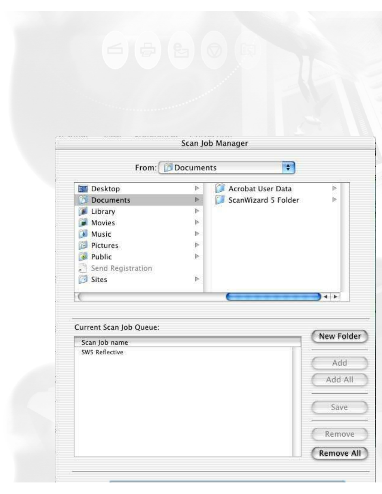
Manager button
This feature lets you save scan jobs that can be loaded at a later time when
necessary. Managing (loading/saving) scan jobs is also useful if you
consistently work in a specific format, scan the same kind of images, or if the
scanner is used by several users who have their own sets of jobs.
The Manager button lets you add, save, or delete scan jobs easily to and from
folders.
To use this feature:
1. Click the Manager button in the Scan Job Queue window.
2. When a dialog box appears, use the function buttons to do the
following:
● To create a new folder for saving scan jobs, click the New Folder
button.
● To add scan jobs from a selected folder to the scan job queue, select
file:///D|/sw56/sjq_win_detail.htm (4 of 6) [8/15/03 4:06:59 PM]
Page 46
Scan Job window
the jobs to be added from the upper half of the dialog box by
highlighting, then click the Add or Add All button.
● To save a copy of a scan job to a selected folder, highlight the scan
job to be saved from the lower half of the dialog box. Next, highlight
the selected folder from the upper half of the dialog box. Finally, click
the Save button.
● To remove scan jobs from the scan job queue, highlight the scan jobs
to be removed, then click the Remove or Remove All button.
file:///D|/sw56/sjq_win_detail.htm (5 of 6) [8/15/03 4:06:59 PM]
Page 47

Scan Job window
●
file:///D|/sw56/sjq_win_detail.htm (6 of 6) [8/15/03 4:06:59 PM]
Page 48

AIC
Advanced Control Panel > Settings window
Advanced Image Correction tools
White/Black Points
Tone Curve
Brightness/Contrast
Color Correction
Filter
Descreen
Threshold
DIGITAL ICE
Automatic Color Restoration
What are the Advanced Image Correction tools?
With the Advanced Image Correction (AIC) tools, you can adjust the
characteristics of your image right from within the ScanWizard 5.
The AIC tools in ScanWizard 5 save you time and provide you with
the needed flexibility to adjust images right within the scanning
software. Experiment with the tools to see what each does to learn
how to optimize your results.
Using the Advanced Image Correction dialog box
When you click on any of the AIC tools, or select Custom... in the
AIC drop-down menu of the Settings window, the AIC dialog box
appears. In this box, you can do the following:
1. These are the thumbnails of the image captured by your
scanner. The left thumbnail is the “before” version — which
shows the effects of the last saved settings values. The right
thumbnail is the “after” version — which shows the effects of
the new settings added in the AIC.
file:///D|/sw56/AIC.htm (1 of 5) [12/16/03 11:58:40 PM]
Page 49

AIC
2. To select another image correction tool, click on the AIC tools
menu of the Settings window, or the AIC tools menu in the
Advanced Image Correction dialog box.
The Action Buttons in the AIC dialog
box
Preview
Thumbnails
AIC tools menu
Current menu
Default button
Revert button
OK button
Cancel button
The Action buttons in the AIC dialog box carry out a specific action.
Preview
If checked, the AIC image correction effect applies to the Preview
image in real time.
Thumbnails
file:///D|/sw56/AIC.htm (2 of 5) [12/16/03 11:58:40 PM]
Page 50

AIC
If unchecked, the “before” and “after” thumbnails become hidden.
AIC tools menu
This drop-down menu lets you bring up any other AIC dialog box.
Current menu
Custom
You can create custom settings in each Advanced Image Correction
control, and then add them to both the current drop-down menu and
the Settings window menu for quick access to those settings.
Add New Custom Setting
To add a custom setting for an AIC tool, click the "Add New Custom
Setting..." in that tool's Current pop-up menu. When a dialog box
comes up, enter the name of the new custom setting to be added.
For instance, the added setting can be called "Debbie's Custom
Setting," as shown below.
Remove Custom Setting
To remove a custom setting for an AIC tool, click the "Remove
Custom Setting..." in that AIC drop-down menu. When a dialog box
comes up, select a custom setting to be removed, then click Remove
in the dialog box.
file:///D|/sw56/AIC.htm (3 of 5) [12/16/03 11:58:40 PM]
Page 51

AIC
Loading/retrieving Custom settings
To load or retrieve a custom setting that you have previously
defined for an AIC tool, select the Custom setting from the AIC dropdown menu. Alternatively, you can choose the setting you wish to
load in that AIC drop-down menu in the Settings window.
Default button
This button restores all settings to their default ScanWizard 5
values.
Revert button
This button cancels out the changes that were made with the current
image-enhancement tool. This means that if you used several AIC
tools, Revert cancels the effect of only the last used (or current)
tool, and preserves the effects of the other preceding tools.
file:///D|/sw56/AIC.htm (4 of 5) [12/16/03 11:58:40 PM]
Page 52

White/Black Points tool
Histogram
The histogram is a graphic representation of how all the pixels in an image
are distributed across brightness and darkness levels. The darkest pixels
are at the left; the lightest pixels are at the right.
A histogram skewed heavily to the left indicates that the image has many
more dark pixels than light. Conversely, a histogram skewed heavily to the
right will indicate a light image as it has more light pixels than dark. The
height of the histogram indicates the number of pixels at that point in the
histogram.
Sliders
The sliders are used to adjust the Black and White points of the image.
The values of the black and white points are reflected in the edit boxes.
Pickers
The Pickers can be used instead of the sliders to set the Black and White
points, based on color values in the preview image. The Picker on the left
sets the Black point; the Picker on the right sets the White point.
● To set the White point: Click the Picker on the right, then click on the
preview image to define the reference point.
● To set the Black point: Click the Picker on the left, then click on the
preview image to define the reference point.
Input, Count, Percent
These figures provide information about the histogram. The figures will
file:///D|/sw56/AIC_WBP_tool.htm (2 of 4) [8/15/03 4:07:52 PM]
Page 53

White/Black Points tool
appear only when the cursor is on the histogram or if a slider is being
moved.
● The Input value indicates the color value of the data displayed in the
histogram.
● The Count value indicates the number of pixels at the Input value. If
Input value is 2 and Count value is 1300, then there are 1300 pixels
in the image at the Input value of 2.
● The Percent value is the percentage of all pixels in the image where
color value is less than or equal to the input value. For example, if
Percent is 15% and Input value is 2, it means that 15% of all pixels
in the image have a value of 2 or less.
Channel
Channel lets you control the shadow and highlight settings for a particular
color channel (red, green, or blue), or for the Master channel (red, green,
and blue simultaneously).
Auto
The Auto button automatically judges the darkest and whitest points and
clips excessive black or white points. The clipping percentage of the
white/black points is accessible by clicking the Setup button.
Setup
This button provides you with advanced controls for setting the white/black
clipping points, as well as for determining the output levels for the
white/black points on your printer.
Using the White & Black Point tool:
1. Choose the Channel in which the histogram will be modified.
❍ If your Image Type is RGB, select Master to modify the tone
curve in the red, green, and blue color channels of the image
simultaneously; or select the color channels individually (red,
file:///D|/sw56/AIC_WBP_tool.htm (3 of 4) [8/15/03 4:07:52 PM]
Page 54

AIC
Example: If you changed the tone curve, applied filters, changed
brightness, then clicked Revert, the brightness changes will be
cancelled, but the altered tone curve and filters settings remain in
effect.
OK button
Clicking on this button will apply whatever Image Corrections you
have performed on the current scan job, and close the AIC dialog
box.
Example: If you increased brightness, changed the saturation, and
then clicked OK, all the changes are applied, and you exit the AIC
dialog box. In the Settings window, the "W&B Points" menu will
display "Custom".
Cancel button
Clicking on this button will cancel out all image correction changes
you have made to the current scan job, and then close the AIC
dialog box. The settings remained unchanged.
Example: If you applied filters, changed the curve, and then clicked
Cancel, none of the changes will take effect, and you exit the AIC
dialog box.
Default button (in the Settings window)
The Default button in the Settings window brings up a dialog box
where you can specify the AIC settings to be reset to their default
values. To reset any or a combination of settings, check the boxes
next to the targeted settings.
file:///D|/sw56/AIC.htm (5 of 5) [12/16/03 11:58:40 PM]
Page 55

White/Black Points tool
Advanced Control Panel > Settings window
White/Black Points tool
The White & Black Points tool is used to change the shadow and highlight
points of an image.
By using this tool, you can manipulate an image to either bring out the
highlights in a very dark image, or bring out more of the shadows in a very
light image. The White & Black Points tool can also be used to neutralize
the color cast in the highlight and shadow regions.
file:///D|/sw56/AIC_WBP_tool.htm (1 of 4) [8/15/03 4:07:52 PM]
Page 56

White/Black Points tool
green, blue) to modify that particular color channel.
❍ If your Image Type is Grayscale, only the Gray channel is
available for selection.
2. Move the black and white sliders to new points on the histogram.
● Moving the black slider to the right will yield more
contrast in the highlight areas of the image, so that more
detail emerges in the highlight areas.
● Moving the white slider to the left will yield more
contrast in the shadow areas of the image, so that more
detail emerges in the shadow areas.
Another alternative is to simply click the Auto button, so that
the the dynamic range for the image is determined
automatically.
3. When the changes are done, click OK. For more details on the effects
of the other action buttons, see the section
The Action Buttons.
file:///D|/sw56/AIC_WBP_tool.htm (4 of 4) [8/15/03 4:07:52 PM]
Page 57

Tone Curve tool
Advanced Control Panel > Settings window
Tone Curve tool
The Tone Curve tool lets you adjust the tonal range of an image. However,
instead of making adjustments using just three variables (highlights,
shadows, and midtones), you can adjust any point along the 0-to-255 scale
(for 8-bit images; 0-to 4096 scale for 12-bit images). The Tone Curve tool
applies to grayscale and all color images and is not available for line art or
halftone scan modes.
file:///D|/sw56/AIC_Tone_Curve.htm (1 of 4) [8/15/03 4:09:12 PM]
Page 58

Tone Curve tool
How to Read the Curve
The Curve shows the relationship of the brightness
changes across the middle pixels between the
resulting image and the original. When you open
the Curves dialog box, the line on the graph is
diagonal because the Input and Output values are
the same.
When the curve is moved up or down, the
relationship between input value and output value
changes accordingly.
● In areas where the curve is moved down,
pixels in that portion of the image are
darkened.
● In areas where the curve is moved up,
pixels in that portion of the image are
lightened.
Contrast in an image can be seen by the angle of
the line. The steeper the slope, the higher the
contrast. The closer the line is to horizontal, the
lower the contrast.
Curve
The Curve is a graphic representation of the tone curve showing scanner
input from dark on the left to light on the right.
Curve Tools
The Curve Tools let you modify the curve. The tools are the curve pointer,
the curve zoom frame, and the curve pane.
file:///D|/sw56/AIC_Tone_Curve.htm (2 of 4) [8/15/03 4:09:12 PM]
Page 59

Tone Curve tool
Use the Curve Pointer tool to define points in the curve that will be
modified. When you click on any point in the curve, a black handle
appears to mark your position. To remove the handle, drag it off the
graph.
Use the Curve Zoom Frame tool to zoom in and out on a particular
point in the curve. Once the area is zoomed in, you can then use
the Curve Pointer tool to define new points for better precision. This
is particularly useful for working with 12-bit images, where more
detail can be seen in such images. The zoom level can be seen in
the Zoom field. To zoom out, click Option.
Use the Pan tool to scroll through the curve if the curve has been
zoomed in. This curve tool can be used only if the curve has been
zoomed in with the Curve Zoom Frame button (above). Otherwise,
the Curve Panel tool will be dimmed.
Input, Output, Zoom:
● Input shows the horizontal value of wherever the cursor is inside the
curve, reflecting the scanner's full depth.
● Output shows the vertical value of wherever the cursor is inside the
curve, reflecting the scanner's full depth.
● Zoom indicates the magnification level of the curve box. At 100%
zoom, the curve is seen in its entirety. Using the Curve Zoom Frame
tool to magnify the curve will zoom in or enlarge your view of the
curve, resulting in a higher zoom percentage.
Method
Method lets you set the kind of curve you wish to have. Select from Line,
Curve, or Gamma.
Channel
file:///D|/sw56/AIC_Tone_Curve.htm (3 of 4) [8/15/03 4:09:12 PM]
Page 60

Tone Curve tool
Channel allows you to choose the color or gray channel in which the gamma
will be affected.
Load
The Load button lets you load a previously saved tone curve for use with
another image. Photoshop-saved curves can also be loaded.
Save
The Save button lets you save a tone curve together with its settings so
that the curve can be used in the future if necessary.
Using the Tone Curve tool:
1. Choose the Channel in which the curve will be modified.
2. If your Image Type is RGB, select Master to modify the tone curve in
the red, green, and blue color channels of the image simultaneously;
or select the color channels individually (red, green, blue) to modify
that particular color channel.
3. If your Image Type is Grayscale, only the Gray channel is available for
selection.
2. Choose the Method in which the curve will be modified. Select from
Line, Curve, or Gamma.
3. Click on the Curve Pointer tool, then click on the gamma curve to
define the points where the curve will be modified. You can then either
raise or lower the curve at that point and see changes to the image
accordingly.
4. When the changes are done, click OK. For more details on the effects
of the other action buttons, see the section
The Action Buttons.
5. To save a curve, click on the Save button. To load a previously saved
curve, click the Load button and specify the curve setting to be loaded.
file:///D|/sw56/AIC_Tone_Curve.htm (4 of 4) [8/15/03 4:09:12 PM]
Page 61

Brightness and Contrast tool
Advanced Control Panel > Settings window
Brightness and Contrast tool
The Brightness & Contrast tool lets you control the brightness and
contrast levels of the entire image. Increasing the brightness makes all
tones in the image lighter. Contrast, on the other hand, is the range
between the darkest and lightest shades in the image, and increasing the
contrast makes greater separation between the darkest and lightest areas
of the image.
file:///D|/sw56/AIC_BC.htm (1 of 2) [8/15/03 4:11:14 PM]
Page 62

Brightness and Contrast tool
Original After Brightness After Contrast
Using the Brightness & Contrast tool:
Drag the scroll bar on the Brightness or Contrast control to change the
settings. Take note of the following:
● Too much brightness can make an image look washed out, while too
little brightness will make the image look dark.
● Too much contrast will make an image look like a photocopy of a
picture, with little or no gray shades left. Too little contrast will make
the colors in the image look dull and flat.
file:///D|/sw56/AIC_BC.htm (2 of 2) [8/15/03 4:11:14 PM]
Page 63

Color Correction tool
Advanced Control Panel > Settings window
Color Correction tool
The Color Correction tool changes the hue and saturation of an image.
You can remove an unwanted color cast by moving the pointer to a
complementary color to balance out the tones. For instance, to remove a
greenish cast from your image, move the pointer in the Wheel to the "red"
area to neutralize the greenish hue of the image. The Color Correction tool
is available only for RGB and indexed color images.
file:///D|/sw56/AIC_Color_Correction.htm (1 of 4) [8/15/03 4:11:52 PM]
Page 64

Color Correction tool
Color Wheel
The Color Wheel allows you to remove a color cast from an image.
Picker
The Picker lets you pick a known neutral gray shade in your image and
adjusts it to a closer, truer gray. The grays in an image may have a
particular color cast which can be verified through the color information in
the Info window. A gray that tends towards a reddish tint, for instance, will
have its R value skewed higher than the G and B values. By using the
Picker on a gray area, the gray is adjusted so that the RGB values become
approximately equal.
Angle
This shows the angle of the pointer on the Color Wheel as measured in
degrees, and a value can also be entered directly in the edit box to move
the cursor to any point in the Wheel.
Example: 0° corresponds to the color red on the Wheel, 60° to the color
yellow, 120° to the color green, 180° to the color cyan, 240° to the color
blue, and 300° to the color magenta.
Original After correction After correction
file:///D|/sw56/AIC_Color_Correction.htm (2 of 4) [8/15/03 4:11:52 PM]
Page 65

Color Correction tool
Radius
This field shows the amount of shift towards a particular color and works in
tandem with the Angle field. The Radius range extends from 0 located at
the center of the Color Wheel and indicating the least concentration of
color, to 1, located at the periphery of the Wheel and indicating the
greatest concentration of color.
Example: If your angle is 0° (red on the Color Wheel) and the radius is 1,
this results in an intense reddish cast on the entire image.
The Angle-Radius feature works differently from that of the Saturation bar,
which increases the saturation of all hues in the image without tending
towards any particular color cast.
Saturation bar
This lets you change the intensity of the hues (colors) in your image. Use
Saturation selectively, because increasing saturation will increase the
intensity of all hues in the image.
Using the Color Wheel:
1. To change the hue of an image, move the pointer in the color wheel
to its new color position in the wheel.
2. To change the saturation of an image, drag on the saturation slide
bar. Dragging the slide bar to the left decreases saturation; dragging
it to the right increases saturation.
file:///D|/sw56/AIC_Color_Correction.htm (3 of 4) [8/15/03 4:11:52 PM]
Page 66

Color Correction tool
3. Use the Angle, Radius, and Picker as necessary.
4. Click on an action button. For more details, see the section
The
Action buttons.
file:///D|/sw56/AIC_Color_Correction.htm (4 of 4) [8/15/03 4:11:52 PM]
Page 67

Filters
Advanced Control Panel > Settings window
Filters
The Filters tool lets you apply or create special effects to your
images. The filters include Blur, Blur More, Edge Enhancement,
Emboss, Gaussian Blur, Unsharp Masking, Sharpen Low, Sharpen
Medium, and Sharpen High.
In using the Filters tool, keep in mind that the image you obtain in
the preview window may differ from the way the image appears
when you finally scan it in. The appearance of the image in the
preview window and how it is affected by a filter will depend on the
resolution of the image. The higher the resolution, the less obvious
the effect of certain filters (such as Blur).
file:///D|/sw56/AIC_Filters.htm (1 of 7) [12/16/03 11:59:27 PM]
Page 68

Filters
Using the Filters:
Click the Current box, and from the drop-down menu that appears,
select the filter to be used.
file:///D|/sw56/AIC_Filters.htm (2 of 7) [12/16/03 11:59:27 PM]
Page 69

Filters
Blur filters
The Blur filters eliminate noise in the parts of the image where
significant color transitions occur. These filters decrease the contrast
between adjacent pixels, making the image appear hazy and out of
focus.
● Blur smooths out the transitions by lightening pixels next to the
hard edges of defined lines and shaded areas.
● Blur More produces an effect three or four times stronger than
Blur.
Before After
Gaussian Blur filter
The Gaussian Blur is used to defocus an area of the image where
significant color transitions occur or where noise exists, and the filter
produces a hazy effect. "Gaussian" refers to the bell-shaped curve
that is generated when this filter adjusts the color values of the
affected pixels. The dialog box below appears when you choose
Gaussian Blur from the Filter menu.
file:///D|/sw56/AIC_Filters.htm (3 of 7) [12/16/03 11:59:27 PM]
Page 70

Filters
The Mask Size determines the depth of the surrounding pixels that
will be affected. The larger the mask size, the stronger the blurring
effect of the filter.
The Threshold allows you to specify a tolerance range or a field of
contrast between adjacent pixels before blurring is applied. Blurring
is applied only when pixel differences are below the Threshold value.
The smaller the Threshold value, the weaker the blurring effect.
The Strength specifies the degree of the filter's effect. The higher
the value, the stronger the blurring effect of the filter
Edge Enhancement filter
The Edge Enhancement filter gives greater contrast to edges. The
filter can do this because edges are areas in an image where gray or
color levels change abruptly. It is best to use this tool for improving
geometrical contoured shapes.
file:///D|/sw56/AIC_Filters.htm (4 of 7) [12/16/03 11:59:27 PM]
Page 71

Filters
Before After
Emboss filter
The Emboss filter makes a selection appear raised or stamped by
suppressing the color within the selection and then tracing its edges
with black.
Before After
Sharpen filters
The Sharpen filters do the opposite of the Blur filters and increase
the contrast of adjacent pixels, making images appear sharper and
more focused.
The three sharpening filters (Sharpen Low, Sharpen Medium, and
Sharpen High) improve clarity. The Sharpen High filter has a greater
sharpening effect than the Sharpen Medium filter, which in turn has a
greater sharpening effect than the Sharpen Low filter.
file:///D|/sw56/AIC_Filters.htm (5 of 7) [12/16/03 11:59:27 PM]
Page 72

Filters
Before After (Sharpen High)
Unsharp Mask filter
The Unsharp Mask filter adjusts the contrast of edge detail and
creates the illusion of more image sharpness. This filter can be useful
for refocusing an image that has become blurry from interpolation or
scanning. You can choose the predefined Unsharp Mask filters in the
Setting window for use, or customize the Unsharp Mask filters by
yourself.
The dialog box below appears when you choose Unsharp Mask from
the Filter menu to customize.
The Mask Size determines the depth of surrounding pixels that will
be affected. The larger the mask size, the stronger the sharpening
file:///D|/sw56/AIC_Filters.htm (6 of 7) [12/16/03 11:59:27 PM]
Page 73

Filters
effect of the filter.
The Strength specify the degree of the filter's effect here. The
higher the value, the stronger the sharpening effect of the filter. Too
much Unsharp Masking will emphasize the noise in the image.
The Threshold defines the required range of contrast between
adjacent pixels before Unsharp Masking is applied. Only the pixels
with the range of contrast between adjacent pixels before sharpening
is applied to an edge. A lower Threshold value produces a more
pronounced effect.
Before After 7x7 After 13x13
file:///D|/sw56/AIC_Filters.htm (7 of 7) [12/16/03 11:59:27 PM]
Page 74

Descreen
Advanced Control Panel > Settings window
Descreen
The Descreen tool lets you remove moiré patterns in the scan process.
Moirés occur when you scan a screened original (mostly reflective
materials, such as pictures from a newspaper or magazine). These
patterns appear to the naked eye like a series of grids of dots or as shown
in the example below.
Before After
Using the Descreen:
1. Click on the Descreen drop-down menu in the Settings window.
file:///D|/sw56/AIC_Descreen.htm (1 of 2) [8/15/03 4:12:46 PM]
Page 75

Descreen
2. When the Descreen menu comes up, select the screen for your
needs, or choose Custom to set your own descreen options.
When the Descreen dialog box comes up, enter a value that
best corresponds to the dot quality of the original in which the
moiré is to be removed. You may use a screen finder to
measure the print screen lpi. Please contact your local print
shop for more information on how to obtain a screen finder.
● Set a value from 50 to 85 if the original image has a coarse dot
pattern, as in images taken from a newspaper.
● Set a value from 100 to 133 if the original image has a fine dot
pattern, as in images taken from a magazine.
● Set a value from 200 to 250 if the original image has a very fine dot
pattern with a near-photographic quality, as in images taken from a
high-quality art magazine.
file:///D|/sw56/AIC_Descreen.htm (2 of 2) [8/15/03 4:12:46 PM]
Page 76

Threshold tool
Advanced Control Panel > Settings window
Threshold tool
For Line Art images, the only AIC tool available is the Threshold tool.
Threshold is the dividing line between black and white; the range is 0 to
255, and the default is 128. Thus, gray levels below the Threshold are
converted to black, while gray levels equal to or above the Threshold are
converted to white, resulting in a high-contrast, black-and-white
representation of the image.
file:///D|/sw56/AIC_Threshold.htm (1 of 2) [8/15/03 4:13:09 PM]
Page 77

Threshold tool
Using the Threshold feature:
1. Drag the sliders to change the Threshold.
❍ To darken the original, drag the slider to the right. This
increases the Threshold value so that more pixels are turned to
black, resulting in a darker image.
❍ To lighten the original, drag the slider to the left. This lowers
the Threshold value so that more pixels are turned to white,
resulting in a lighter image. Take note that both Darken and
Lighten controls use the same slider (the black slider).
2. Alternatively, you can enter a value in the Threshold edit box to
change the Threshold.
3. The Sharpen option lets you sharpen the Line Art image.
file:///D|/sw56/AIC_Threshold.htm (2 of 2) [8/15/03 4:13:09 PM]
Page 78

Digital ICE for Photo Prints
DIGITAL ICE for Photo Prints
Before After
The DIGITAL ICE option is part of Microtek's exclusive PictuRescueTM
system for automatic photo reconstruction and restoration.
The "DIGITAL ICE" feature lets scanners that implement DIGITAL ICE
automatically remove dust, scratches, cracks, creases, folds, and other
defects from images to be scanned, resulting in markedly visible
improvements.
The DIGITAL ICE function is
provided as a pull-down menu for
scanners supporting this feature.
For the pull-down menu, two or
three options are available
(depending on the scanner model) -None and Strong; or None, Normal,
and Strong.
Note: The DIGITAL ICE feature is
designed to work with continuoustone reflective image originals such
as photos. It is not designed to
work with negatives,
transparencies, and printed matter.
In addition, when the Descreen
feature is selected, the DIGITAL ICE
option is dimmed and will not be
available for selection.
file:///D|/sw56/aic_digital_ice.htm (1 of 2) [12/17/03 12:01:08 AM]
Page 79

Automatic Color Restoration
Automatic Color Restoration
Before After
The Automatic Color Restoration feature is part of Microbe's Colones
system for bringing faded colors back to life.
Note:
● This option will not work when
the Image Type is set to "Line
Art" or "Black and White
Diffusion."
● For best results when using
the "Automatic Color
Restoration" feature, marquee
(select) only the image area of
the photo to be restored (the
photo proper). Do not include
the white border around the
photo, as inclusion of the
background may lead to
inaccurate color restoration.
file:///D|/sw56/AIC_restorColor.htm (1 of 2) [12/17/03 12:02:23 AM]
Page 80

Automatic Color Restoration
To use Automatic Color Restoration function:
1. In the Preview window of the Advanced Control Panel, marquee the
faded image area to be restored.
2. In the Settings window, check the "Automatic Color Restoration"
option.
3. Click the "Scan To" button to perform scanning. Automatic Color
Restoration is applied, and faded colors in the photo are restored.
file:///D|/sw56/AIC_restorColor.htm (2 of 2) [12/17/03 12:02:23 AM]
Page 81

AIC_ACE
Automatic Color Enhancement
After Before
The Automatic Color Enhancement feature improves the contrast and saturation of an
image, resulting in more vibrant colors.
In the Standard Control
Panel, check the "Auto Image
Enhancement" option to
enable Automatic Color
Enhancement function. If this
option is unchecked, the
scanned image will appear like
the original, with no image
enhancement applied.
To use the Automatic Color
Enhancement function:
1. Click the Preferences
button to display the
Preferences window.
2. Check the "Auto Image
Enhancement" option,
then press the OK
button.
3. Click the "Scan To"
button to perform
scanning. The resulting
enhanced image displays
shortly afterwards.
file:///D|/sw56/AIC_ACE.htm (1 of 2) [12/17/03 12:03:16 AM]
Page 82

AIC_ACE
In the Advanced Control Panel, if
the "Color Enhancement" feature is
checked, this box has two options:
Automatic and None. Before
selecting the "Automatic" option,
the "RGB Color Matching" option
should be checked first.
If the "Automatic" option is
selected, a color enhancement
algorithm applies. If the "None"
option is selected, the scanned
image will appear like the original,
with no image enhancement
applied.
To use the Automatic Color
Enhancement function:
1. Select the "Color Matching
Setup" command from the
Preferences menu of the
Preview window. The Color
Matching Setup window
appears.
2. Check the "RGB Color
Matching" option.
3. Select "Automatic" on the
"Color Enhancement" option,
then press the OK button.
4. Click the "Scan To" button to
perform scanning. The
resulting enhanced image
displays shortly afterwards.
file:///D|/sw56/AIC_ACE.htm (2 of 2) [12/17/03 12:03:16 AM]
Page 83

AIC_ASC
Automatic Sharpness Correction
Before After (Sharpen High)
The Automatic Sharpness Correction feature emphasizes the edges
(contours) of an image, contributing to increased sharpness.
To use the Automatic Color
Enhancement function:
1. In the Settings window, select
the Filter drop-down menu.
2. From the drop-down menu,
select your sharpening option
from Low, Medium, and High.
Alternatively, you can also
select the sharpening option
from the "Advanced Image
Correction: Filter" window.
3. Click the "Scan To" button to
perform scanning. The
resulting sharpened image
displays shortly afterwards.
file:///D|/sw56/AIC_ASC.htm (1 of 2) [12/17/03 12:03:47 AM]
Page 84

AIC_ASC
file:///D|/sw56/AIC_ASC.htm (2 of 2) [12/17/03 12:03:47 AM]
Page 85

FAQ's
Frequently Asked Questions
How do I access the Microtek Scanner Configuration (MSC) Utility?
How do I test if my scanner is working properly?
What is Kodak Color Management System?
How do I calibrate my monitor?
file:///D|/sw56/FAQ's.htm [8/15/03 4:14:52 PM]
Page 86

Do I have access to the Microtek Scanner (MSC) Utility?
Do I have access to the Microtek Scanner
Configuration (MSC) Utility?
The Microtek Scanner Configuration (MSC) utility is a companion program
of ScanWizard 5. This utility works only if your scanner model is equipped
with Smart-Touch buttons located on the front panel of the scanner. If
your Microtek scanner is equipped with Smart-Touch buttons, you can use
the buttons to complete common scanning tasks.
How to configure the Smart-Touch buttons with MSC utility
1. Launch the MSC Utility by double-clicking the Microtek Scanner
Configuration icon from the desktop.
2. When the MSC panel appears, click on a tab to redefine the settings
you want.
Note:
ScanWizard 5 and MSC are programs that run exclusively. This means that
ScanWizard 5 and MSC should be used one at a time and not
simultaneously.
How ScanWizard 5 works with the scanner buttons
When ScanWizard 5 is launched from the desktop, the Scan, Copy, or Email buttons will complete an overview and set the "Scan To" button in
ScanWizard 5 to reflect the scan function you chose.
When ScanWizard 5 is launched from an image-editing application, the
Scan, Copy, or E-mail buttons will perform only a prescan.
Relationship between MSC and the scanner buttons
The MSC utility is available for you to set parameter settings for the
respective scanner button. When MSC is launched, press the button to
carry out its corresponding function.
file:///D|/sw56/utl_MSC.htm [8/15/03 4:15:28 PM]
Page 87

How do I test if my scanner is properly working?
How do I test if my scanner is properly
working?
The Microtek Scanner Finder is a utility included with ScanWizard 5 that
allows you to verify if your scanner has been properly set up and
connected to your Macintosh.
To test, double-click the Microtek Scanner Finder icon on the bottom of
the desktop, choose the View command, Show Scanner(s) Information
from the Microtek Scanner Finder System menu bar. The found
scanners will be listed, as shown below.
file:///D|/sw56/utl_test.htm [8/15/03 4:15:57 PM]
Page 88

file:///D|/sw56/utl_kcms.htm
What is Kodak Color Management
System?
This section is copyrighted by, and licensed from, Eastman Kodak
Company.
KCMS Overview
Some Background Information
Everyone perceives colors differently. Even the same person’s perception
can be affected by different lighting conditions. Different devices (input,
display, and output) also interpret and define color differently and simply
can’t create the same gamut (or “range”) of colors.
The goal of color management, then, is to help you get accurate,
predictable color across all devices by managing, compensating for, and
controlling these differences.
The Idea Behind Color Management
Each type of device reads, displays, or interprets color in a unique way.
This unique interpretation is called a “device dependent color space.” And
while there are groups of color spaces, such as RGB or CMYK each device
is still unique within its group. For example, monitors display color in RGB,
yet each monitor displays a unique version.
The CMS automatically translates between each device dependent color
space—so the color data is accurate and understandable.
This chart shows the central role of the CMS in managing device
dependent color spaces.
file:///D|/sw56/utl_kcms.htm (1 of 6) [8/15/03 4:16:23 PM]
Page 89

file:///D|/sw56/utl_kcms.htm
How Color Management Works
The aim of color management is to preserve true color information by
making up for the differences in the way devices communicate color. Your
CMS does this by using a scientifically designed system including:
● A Color Matching Processor
● A Device-Independent color space, frequently called a Reference
Color Space or Profile Connection Space (PCS), which acts as a
Rosette Stone in the translation process
● Device Color Profiles (DCPs)
DCPs relate a device dependent color space to the Profile Connection
Space. The CMS uses the Color Profile to translate from one device
dependent color space to another.
How CMS Translates between Devices
When you scan an image, a CMS uses the information about the
scanner—stored in the Scanner Color Profile—to translate the RGB image
from the scanner to the Profile Connection Space. The CMS then uses the
file:///D|/sw56/utl_kcms.htm (2 of 6) [8/15/03 4:16:23 PM]
Page 90

file:///D|/sw56/utl_kcms.htm
information about your monitor—stored in the Monitor Color Profile—to
translate the image from the Profile Connection Space to your monitor
color space, where you see it displayed.
In this example, the scanner is the “source” device, and the monitor is the
“destination” device.
When you print the image, the CMS again translates the image data from
the monitor’s RGB color space to the printer’s RGB color space—using the
information about both devices as stored in their Color Profiles.
So, although all of the devices in this example use different device
dependent color spaces, the CMS is able to translate between them and
produce accurate, predictable color.
What are Device Color Profiles
Color Management Systems use Device Color Profiles to interpret color
data between devices. DCPs are a collection of one or more ICC Profile
data files. ICC Profiles contain color characteristics of a given device
(input, display, or output).
ICC profiles conform to the International Color Consortium profile
specification, allowing the same device profiles to be used across multiple
platforms.
file:///D|/sw56/utl_kcms.htm (3 of 6) [8/15/03 4:16:23 PM]
Page 91

file:///D|/sw56/utl_kcms.htm
Where Do Color Profiles Come From?
Color Profiles are created by either Kodak scientists or other color
professionals using specialized software packages, sometimes known as
profile building tools.
Kodak scientists use sensitive, specialized equipment to measure the color
characteristics of a representative example of each device, as supplied by
the manufacturer, to determine the intrinsic properties of the device.
From these measurements they develop a “characterization” of the device,
called a Device Color Profile, for each make and model measured.
The Color Profile includes color tables that relates the device’s color space
to a Profile Connection Space, as well as information about key attributes
of the device for use by CMS-based applications.
A Word about Source and Destination
People often get confused about what is the “source” of an image and what
is its “destination,” so let’s clarify this.
In general, the “source” of an image refers to where the image currently
is, and the “destination” is where you want the image to go.
In CMS terms, “source” means the Color Profile used to bring the image
data into the Profile Connection Space (PCS). “Destination” means which
Color Profile is used to get it from PCS to the destination device. For
example, when you scan in an image, you want it to appear on your
monitor. So the source is your scanner, and its related Color Profile, and
the destination is your monitor, using its Color Profile.
file:///D|/sw56/utl_kcms.htm (4 of 6) [8/15/03 4:16:23 PM]
Page 92

file:///D|/sw56/utl_kcms.htm
Likewise, when you open a Photo CD image, the source is the Photo CD,
plus the Color Profile that relates the color data to the PCS, and the
destination is the monitor, plus the Color Profile that relates the PCS to the
monitor’s color space.
Here’s another example: Let’s say you manipulate the image on your
monitor screen, and print it.
The source this time is the monitor (plus the Color Profile that relates it to
the PCS), and the destination is a printer (plus the Color Profile that
relates the PCS to the printer’s color space).
So, Source and Destination mirror a logical two-step process most Color
Management Systems use to translate images between device color
spaces;
● The Source Profile brings the image into the PCS
● The Destination Profile connects the image from the PCS to the
output device, such as a Monitor, Printer, or Proofer.
However, this is not the case with a Kodak CMS.
Kodak has patented its composition technology. This technology takes the
Source and Destination Profiles and composes them into a single color
transforming profile.
This technology adds significant improvement in the quality and
performance of the Color Management System.
Note: You use the Source/Destination information when you setup or use
your CMS-based application, such as PageMaker 6.5.
file:///D|/sw56/utl_kcms.htm (5 of 6) [8/15/03 4:16:23 PM]
Page 93

How do I calibrate my monitor
How do I calibrate my monitor?
Color Matching Information
This section contains supplementary information on further steps you need
to take to achieve color matching across your devices.
Calibrating your monitor
Calibrating your monitor to obtain the proper monitor profile is important
for achieving higher precision in color matching. ICC profiles for your
monitor may be created specifically by profiling your monitor through the
following utilities:
● The "Calibrate" function under "System Preferences...Displays" of
Apple menu
● Any third-party calibration programs or hardware calibrator
You can also obtain your monitor profile by checking with the
manufacturer of your monitor.
Setting up the System (Monitor Profile)
After creating or identifying the monitor profile, you need to select the
monitor profile to make sure the image is displayed correctly.
file:///D|/sw56/utl_calibrate_monitor.htm [8/15/03 4:17:26 PM]
Page 94

Basic Scanning Concepts
Basic Scanning Concepts
This section covers basic scanning concepts. If you already have basic
scanning knowledge, you may skip this section.
What is a scanner
Type of scanners
Components of effective scanning
Image types
Text scanning
A rule of thumb for choosing the right Quality Factor is, for images with
printing screens less than or equal to 133 lines per inch, set Quality Factor
to 2; above 133 lines per inch, set it to 1.5; for continuous tone printers,
set it to 1.0.
If you are outputting images to a monitor (such as doing multimedia
work), you need not scan images higher than 72 ppi, as monitors are
capable of only showing images up to 72 ppi. A higher-resolution image
will not be any clearer on the monitor and will simply create larger files.
Remember that the higher the resolution, the larger your image file will
be. For instance, an 8.5" x 11" color photograph scanned at 75 ppi takes
up about 1.6 megabytes (MB). Doubling resolution to 150 ppi will increase
the file size four times - to approximately 6.3MB! Going to 300 ppi will
increase file size to 26.2MB.
What you need to do is to select the lowest possible resolution that still
gives you good image quality in order to keep file sizes manageable.
What is a scanner
A scanner is a device that captures an image and converts it into a digital
file:///D|/sw56/Basic.htm (1 of 5) [8/15/03 4:18:11 PM]
Page 95

Basic Scanning Concepts
form that your computer can display, edit, store, and output. The image
may be a photograph, page of text, drawing or illustration, or even a
relatively flat, three-dimensional object such as bolt or fabric. In practice,
this means you can use your scanner to do the following:
● Incorporate artwork or photos into documents
● Scan printed text into your word processor and eliminate retyping
● Scan faxed documents into a database or word processor
● Add images to multimedia productions
● Integrate visuals into presentations to make them communicate more
effectively.
With a basic understanding of how scanners work, the types of scanners
available, and what they are capable of doing, you can improve the quality
and efficiency of your work.
Type of scanners
Scanners can be classified into three general types:
● Flatbed scanners, which are used to scan photographs or prints.
Flatbeds have a glass surface on which the materials to be scanned
are placed.
● Transparency and slide scanners, which are used to scan transparent
materials such as filmstrips and slides.
Components of effective scanning
The scanner is only one part of the scanning system. In addition to the
scanner, you need these other components:
● A cable to connect your scanner and computer
● Scanning software that controls how the scanner works
file:///D|/sw56/Basic.htm (2 of 5) [8/15/03 4:18:11 PM]
Page 96

Basic Scanning Concepts
● Image-editing software to integrate scanned images into your work;
or OCR software to integrate scanned text into your work.
● A suitable monitor to display color and grayscale images
● A device for outputting your work such as a black and white or color
printer, dye sublimation printer, image setter or other color proofing
device.
In addition to the basic components, you can use these scanner
accessories to make your scanning even more effective:
● Transparent Media Adapter (TMA): for scanning slides, filmstrips, and
transparencies
● Auto Document Feeder (ADF): Helps with text scanning by allowing
continuous scanning of up to 50 pages of text.
Image types
For a computer to represent image information in a digital format, the
computer uses units of picture elements, or pixels.
An image file, for instance, is simply a representation of hundreds,
thousands, or even millions of pixels arranged in a grid, and computers
record the intensity and color of a pixel in 1 or more bits of data. The
greater the number of bits, or bit-depth, of an image, the more
information it can store. For easy classification, images can be categorized
into single-bit, grayscale, or color.
CMYK CMYK-C CMYK-M CMYK-Y CMYK-K
file:///D|/sw56/Basic.htm (3 of 5) [8/15/03 4:18:11 PM]
Page 97

Basic Scanning Concepts
RGB RGB-R RGB-G RGB-B
GrayScale Indexed Lab1 Lab2
Single-bit
Single-bit images are the simplest kind, using just one bit of data to record
each pixel. Single-bit images come in two types: line art, and error
diffusion.
● Line Art includes anything that is black and white, such as a pencil or
ink sketch. Line Art may also include one-color image, such as
mechanical blueprints or drawings.
● Error Diffusion reproduction of images that gives the illusion of gray
but only because the black and white dots (or pixels) comprising the
image are arranged in such a way as to fool the eye to see gray. This
is because when Error Diffusion is printed, dark areas are represented
by darker dots coming together, while lighter areas are those with
scattered dots. An example of halftone images would be the pictures
you see in a newspaper or magazine.
Grayscale
Grayscale images contain more than just black and white, and include
actual shades of gray. In a grayscale image, each pixel has more bits of
information encoded in it, allowing more shades to be recorded and shown.
For instance, four bits are needed to reproduce up to 16 levels of gray.
Going higher, eight bits can reproduce the 256 levels of gray required to
represent most black-and-white photos accurately.
file:///D|/sw56/Basic.htm (4 of 5) [8/15/03 4:18:11 PM]
Page 98

Basic Scanning Concepts
Color
Color images contain the most complex information. To capture color
images, scanners use a process based on the RGB (Red, Green and Blue)
color model, where every color is composed of a varying amount of the
three colors. In the RGB model, the absence of white light creates black,
the complete saturation of light creates white (100% if red, green, and
blue), and equal amounts of red, green, and blue create intermediate
shades of gray.
Depending on the type of scanner you have, your scanner can record 24
bits for the three RGB channels. This means your scanner can record and
reproduce an enormous amount of color information - anywhere from 16.7
millions colors for 24-bit scanners.
Selecting an image type
Depending on the scanner you have, you will be able to scan different
types of images according to your needs. You can scan an image and
output it in its original form, or you can output it in another form and get
some interesting effects.
For instance, you can scan a color photo and output it in its original form
as a color photo, or you can output it as a gray to create a new look.
Whatever you do, however, keep in mind that the quality of the original is
very important in determining the quality of the final scanned image.
Text Scanning
Aside from scanning images, your scanner can scan text and deliver it into
your word processor, eliminating the need for retyping. This is done
through the use of Optical Character Recognition (OCR) software, which
converts scans to text and retains text formats through the software's
ability to recognize the shapes, shades and lines that make up individual
characters.
file:///D|/sw56/Basic.htm (5 of 5) [8/15/03 4:18:11 PM]
Page 99

Quick Tips for Best Scans
Quick Tips for Best Scans
Whenever you scan, keep some goals in mind. How do you want the final
scanned image to look? Where will it be used? What image-editing
software will you use? How will the image be reproduced, on what type of
printer and what type of paper?
With these goals in mind, you can then proceed to obtain quality scans.
Here are a few tips to consider to obtain the best scans.
Get the necessary hardware
Use a good original
Keep your scanner clean
Select the right image type and settings
Use your image correction tools
Get the necessary hardware
Take note of the following:
● Make sure you have enough RAM and available storage space in your
computer. Scanned images need more memory than text files, so you
may need to add RAM and storage.
● Check if your video card and monitor support the resolutions you
need to display high-quality images. For optimal quality, use a 24-bit
(also known as True Color) card that is set to "millions of colors" or
"16.7 million colors."
Use a good original
A good original is still important in determining the final quality of the
scanned image. Even if your scanning software or image-editing package
file:///D|/sw56/Tips.htm (1 of 3) [8/15/03 4:18:45 PM]
Page 100

Quick Tips for Best Scans
has tools to improve image quality, they work only up to a certain point.
Images that are out of focus, dirty, or poorly exposed may never look
great - no matter how much time and effort you spend retouching them.
ScanWizard 5 scans halftone images such as magazine photos using
special settings. If you scan magazine or newspaper photos without
descreening the image, you will obtain something called a moiré, which is
an undesirable pattern in color printing and appears as a series of dots or
grids on your image.
Keep your scanner clean
Make sure your scanner glass is clean before you scan images. This way,
you don't pick up flecks of dust along with the image when you scan. To
clean the scanner glass, use alcohol on a lint-free cloth and clean the glass
carefully.
Select the right image type and settings
Choose the right image and set the correct resolution and scaling before
you scan.
● If you have single-color art (even if it isn't black and white), scan it
as line art.
● For black and white photos, scan these as grayscale (not color) to
generate smaller files.
● If you plan to print a color scan in black and white, scan it in
grayscale.
Finally, when scanning (whether in color or another mode), choose the
correct resolution.
Use your image correction tools
When scanning color images to obtain more accurate colors, use the
ScanWizard 5's Color Matching System and the Advanced Image
Correction feature.
file:///D|/sw56/Tips.htm (2 of 3) [8/15/03 4:18:45 PM]
 Loading...