

Page 1
Supplement
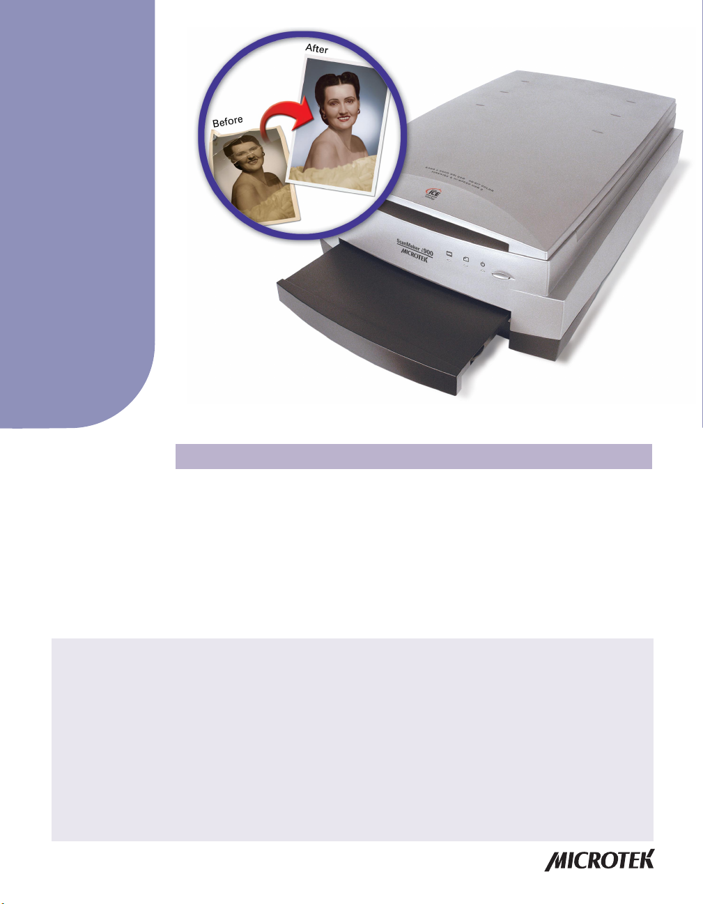
ScanMaker i900 features, scenarios, and information
Getting to Know Your ScanMaker i900
The ScanMaker i900 is a dual media flatbed with 6400 x 3200 dpi resolution, 4.2
maximum optical density , 8.5" x 14" legal-size scan bed for the upper bed, and 8"x10"
lower bay for scanning transparencies. The scanner features the PictuRescue™
system with DIGIT AL ICETM Photo Print Technology to reconstruct damaged photos,
plus ColoRescue™ one-touch color restoration for both photos and film. Also
featured is the Microtek-patented Emulsion Direct Imaging T echnology™ (E.D.I.T .™)
for producing clear, distortion-free images in transparency scanning.
Contents
Getting to Know Your ScanMaker i900 ........................................................... 1
Features of the ScanMaker i900 ...................................................................... 2
Taking a Closer Look ........................................................................................ 3
Unlocking the Scanner .................................................................................... 4
Connecting the FireWire Port ......................................................................... 5
DIGITAL ICE Photo Print Technology ............................................................. 7
Positioning Your Originals .............................................................................. 8
Using the Glass Holder ......................................................................... 10
Using the Other Film Holders ............................................................... 11
A. Using the 35mm Slide Holder ................................................. 12
B. Using the 35mm Filmstrip Holder ........................................... 12
C. Using the 120 Film Holder ........................................................ 14
D. Using the 4" x 5" Film Holder ................................................... 15
Scanning Scenarios ....................................................................................... 17
Copyright © 2004 Microtek International, Inc. http://www.microtek.com
I49-003886 A, November 2004
Scanning Regular, Non-Damaged Photos .......................................... 17
Scanning Damaged Photos ................................................................. 21
Scanning Positive Film ......................................................................... 24
Scanning Negative Film ........................................................................ 27
Using the Microtek Scanner ICC Profiler (MSP) .......................................... 30
Calibration Kit ........................................................................................ 30
MSP Installation .................................................................................... 30
Positioning the Target ........................................................................... 30
A. Positioning the Reflective Target ............................................. 31
B. Positioning the Transparent Target .......................................... 31
Calibration Setup ................................................................................... 32
Calibration and Profiling ....................................................................... 33
Loading a Profile ................................................................................... 34
Specifications / System Requirements ........................................................ 35
FCC Compliance Statement .......................................................................... 36
Page 2

Features of the ScanMaker i900
The ScanMaker i900 comes with several important features, including the following:
• Microtek's PictuRescue system: This combined photo reconstruction and
restoration solution incorporates DIGIT AL ICE Photo Print Technology and
ColoRescue.
– With DIGIT AL ICE Photo Print T echnology , the ScanMaker i900 can
automatically map, identify , and eliminate surface defects on your photos. Built
into the hardware and software, DIGIT AL ICE Photo Print T echnology removes
dust, scratches, rips, and tears, reconstructing your damaged photos and
restoring them to pristine, near-original quality .
– With ColoRescue, the ScanMaker i900 restores faded colors in photos and film,
bringing hues back to their original luster and brilliance for more vibrant
images. ColoRescue's one-click, automatic color recovery process is simple
and straightforward, involving no learning curve or hassle.
• Dual FireWire and Hi-Speed USB interfaces: W ith a data transmission rate of
400Mbps, FireWire is the most appropriate interface for high-resolution image
transfer. High-Speed USB (USB 2.0) , which is capable of 480Mbps data transfer ,
provides plug-and-play connectivity for a hassle-free installation.
• Microtek's Emulsion Direct Imaging T echnology (E.D.I.T .): This is a patented
“glassless” scanning system built into the lower bay of Microtek’s dual media
scanners, allowing the scanner CCD to directly read the emulsion side of the film
during scanning without any interfering pane of glass. This effectively eliminates
problems associated with normal glass transparency scanning like Newton Rings,
resulting in distortion-free images.
• Microtek ScanWizard™ Pro scanning software: This is an advanced scanner
controller program that provides many powerful, professional-level features for
scanning. ScanWizard Pro includes the Microtek Scanner ICC Profiler (MSP)
program, which allows users to calibrate the scanner and generate the appropriate
ICC color profile to ensure color consistency and accuracy during the scanning
process. ScanWizard Pro also features two color spaces, allowing users to work in
the Native CMYK / RGB mode, as well as in the intuitive LCH (Lightness, Chroma,
Hue) mode.
2 ScanMaker i900 Supplement
Page 3
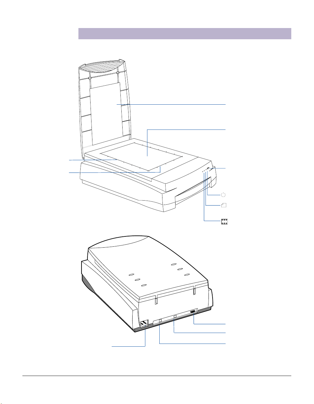
Vertical ruler
Horizontal ruler
Taking a Closer Look
Scanner lid
Glass surface
(Upper scan bed)
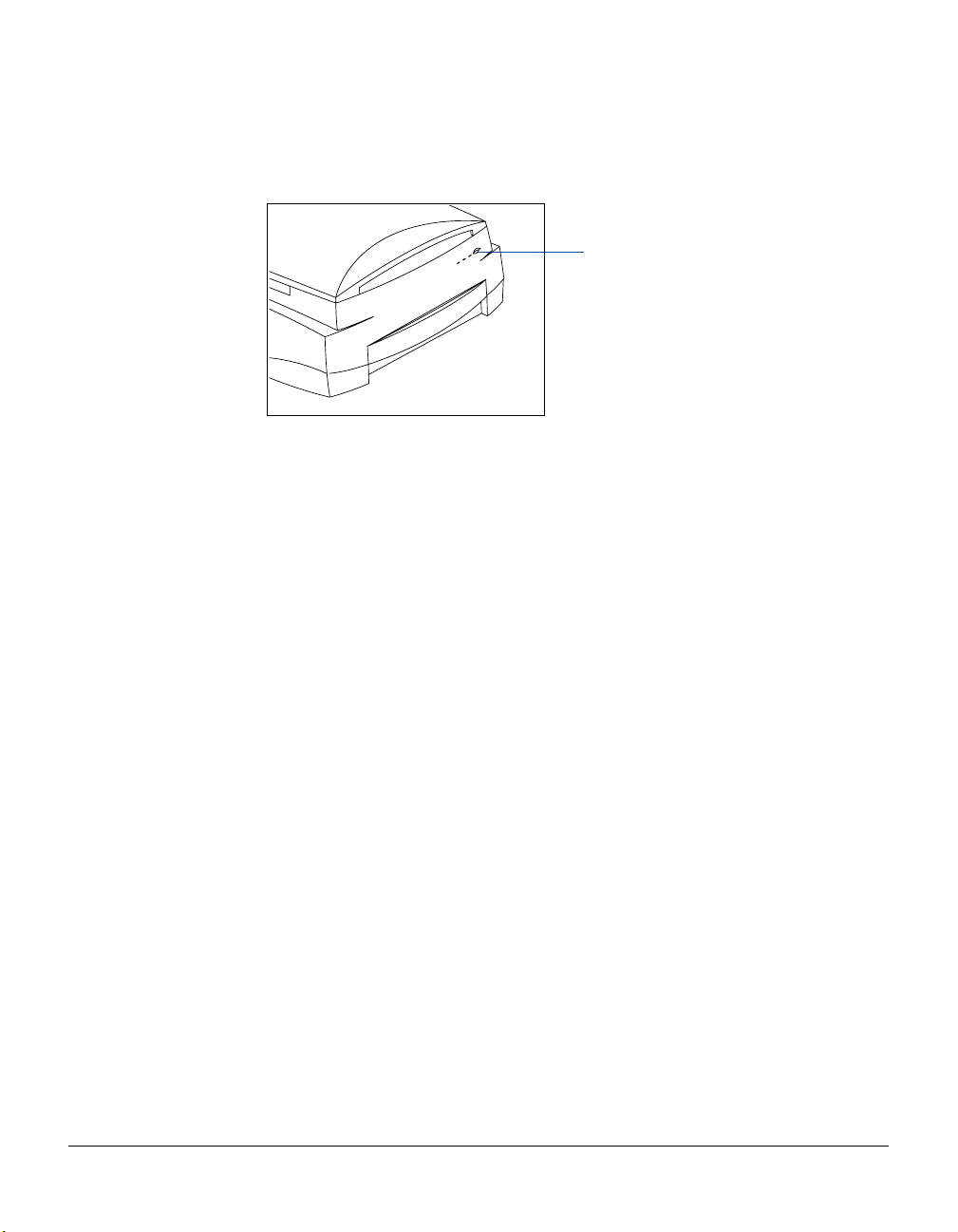
Power button
Power indicator (green)
Reflective Ready
indicator (amber)
Transparency Ready
indicator (amber)
Power connector
Accessory port
FireWire port (1)
Hi-Speed USB port (1)
ScanMaker i900 Supplement 3
Page 4
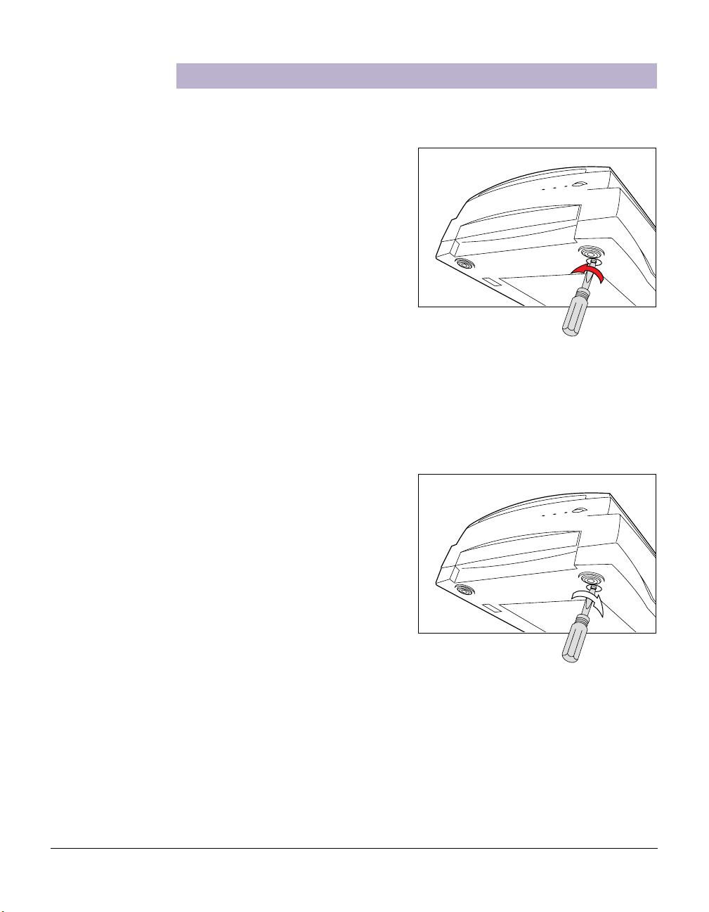
Unlocking the Scanner
Before you can operate the scanner, you will need to unlock the scanner. To unlock
the scanner, follow the steps below:
1 . Remove the yellow “Step 3” sticker
from your scanner.
2 . Look for the unlocking screw at the
bottom of the scanner.
3. Using a screwdriver, push and turn
the locking screw counterclockwise
to the unlock position.
When successfully unlocked, the
screw will push out a little,
protruding slightly from the bottom
of the scanner.
Shipping the Scanner
If you have to transport the scanner, you will need to lock the scanner back. Follow
the steps below:
1. Turn off the scanner if your scanner
is on.
2. Turn the scanner back on. The
scanner’s carriage will move to the
standby position in 5 minutes.
3. When the indicators on the front of
your scanner stop blinking, use a
screwdriver, and then push and turn
the locking screw clockwise to the
locked position.
When the screw has been tightened, this indicates that your scanner is locked.
4. Turn off your scanner. The scanner is now ready for transport.
4 ScanMaker i900 Supplement
Page 5
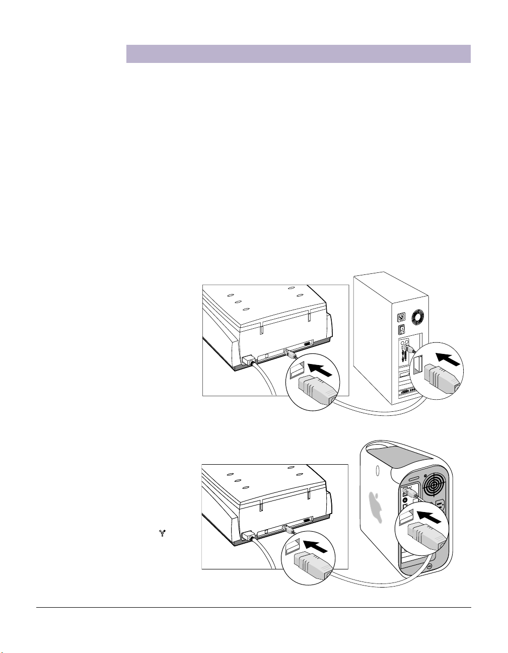
Connecting to the FireWire Port
The printed Start Here guide showed you how to connect your computer to the USB
port of the ScanMaker i900. Here, the Supplement shows you how to connect the
computer to the scanner's alternate FireWire port.
Prior to connection, check first to see if your computer system has a FireWire port. If
FireWire is present, connect the FireW ire cable to the FireW ire port. If your computer
does not have a FireWire port, install a FireW ire card to make use of the FireW ire port.
For details on how to install a FireWire card in your computer , refer to the
documentation that came with the FireWire card.
Note: Your ScanMaker i900 does not include a FireWire card in the package.
Follow the steps below to perform the FireWire connection:
1. Connect one end of the FireWire cable to your computer, and connect the other
end of the cable to the scanner’s FireW ire port.
(with a built-in FireWire port
or FireWire card installed)
(with a built-in FireWire port)
The latest Macintosh
computers (i.e., G3, G4, G5,
etc.) are equipped with a built-
in FireWire port, usually
labeled with the “ ” logo.
For PC users
For Mac users
ScanMaker i900 Supplement 5
Page 6
2. Press the Power button on the front panel of the scanner, and wait for the lights to
stop blinking and stay on steady.
The scanner will be detected by your system automatically.
Power button
6 ScanMaker i900 Supplement
Page 7

DIGITAL ICE Photo Print Technology
DIGITAL ICE Photo Print Technology is an advanced technology that reconstructs
damaged photos during the scanning process, transforming the traditional photo
restoration process into one that is automatic, fast, and economical. Unlike softwareonly correction, DIGIT AL ICE Photo Print T echnology is built into your ScanMaker
i900, providing a seamless reconstruction process that brings damaged photos back
to near-original condition.
The Reconstruction Process
DIGIT AL ICE Photo Print Technology creates a defect map to identify the precise
locations of physical defects or visual “noise” on the print being scanned. The
scanner's differential shadowing technology and proprietary software algorithms then
quickly and automatically eliminate the unwanted defects.
In addition, Microtek has developed a unique Image Registration Technology that is
built into your scanner to ensure precise color registration and superior image quality.
Because two scanning passes and two lamps are required in the use of DIGIT AL ICE
Photo Print Technology, precise registration is crucial in order to produce a perfectly
aligned image from the twin scanning passes. Microtek's Image Registration
Technology ensures accurate movement of the scanner mechanism, so that the
mechanical steps during the scanning process are registered with the ultra-fine
precision needed for superior, accurate scans.
Using Applicable Scan Materials
DIGIT AL ICE Photo Print Technology is used in the ScanMaker i900 to reconstruct
damaged photos. It is not designed to be used for printed materials from newspapers
and magazines, or printouts from inkjet/laser printers.
ScanMaker i900 Supplement 7
Page 8
Positioning Your Originals
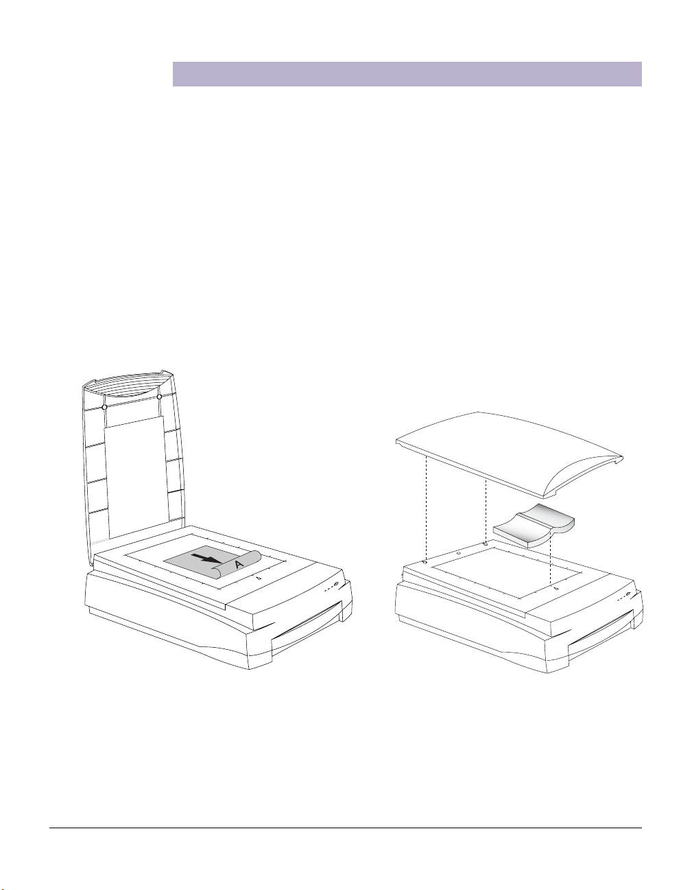
Positioning Reflective Originals
This procedure applies when you use the upper scan bed of the ScanMaker i900 to
scan reflective materials such as photos and prints.
1. Open the scanner lid.
2. Place the original to be scanned face down on the scanner glass bed, towards
the front of the scanner. Center the top of the original along the horizontal ruler
on the scanner.
Note: To scan a book or thick materials/documents, lift the scanner lid out of its
hinge sockets high enough to create room between the originals and the lid.
3 . Lower the scanner lid.
8 ScanMaker i900 Supplement
Page 9
Positioning Transparent Film
This procedure applies when you use the lower scan bed of the ScanMaker i900.
There are two ways to scan transparent film:
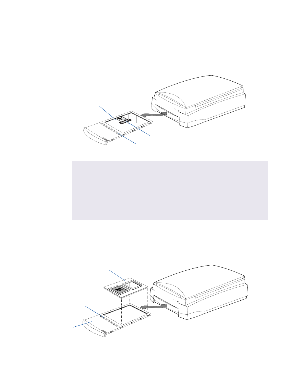
A. By using the Glass Holder to scan non-standard-size transparent film.
Glass Holder
Vinyl strip
Calibration strip
Important:
When using the Main Holder or the Glass Holder, make sure you use the correct
side up when inserting the holders into the scanner. The correct side up is the
side showing the holder labels facing up.
Make sure that the calibration strip on the holders are kept clear and free of
obstruction at all times; no material should ever be placed on this area. Also, make
sure the calibration strip faces the front of the scanner when you insert the
holders into the lower compartment of the ScanMaker i900.
Calibration strip
Main Holder
B . By using the Main Holder, which is used together with individual film holders to
scan standard-size transparent film, such as 35mm slides, 35mm filmstrips, 120 film,
or 4" x 5" film.
4" x 5" Film Holder
ScanMaker i900 Supplement 9
Page 10
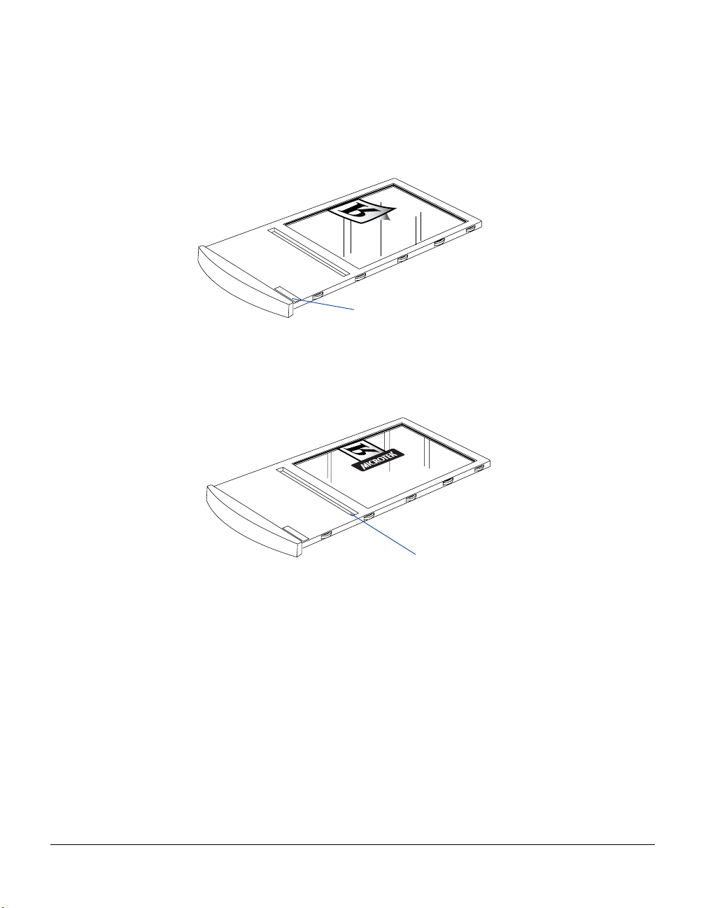
Using the Glass Holder
The Glass Holder is used to scan non-standard-size transparencies.
1 . Place the film face down on top of the glass surface of the holder.
GLASS HOLDER
Orient Glass Holder with "Glass
Holder" label facing up
2. Secure the transparency to the glass by using the vinyl strips provided with
your scanner.
3 . Insert the holder all the way into the transparency bay (the drawer or lower
compartment) of the scanner.
Note: The Glass Holder requires regular cleaning. To clean, use mild glass
cleaning solution, and wipe the glass plate gently with lint-free, lens-cleaning
cloth to prevent leaving fiber residue.
10 ScanMaker i900 Supplement
GLASS HOLDER
Keep calibration strip clear
and free of any obstruction
Page 11
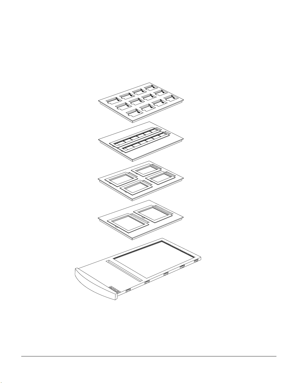
Using the Other Film Holders
The other Film Holders are used together with the Main Holder to scan standard-size
film. For instance, use the 4" x 5" Film Holder to scan 4" x 5" film, or use the 35mm
Filmstrip Holder to scan 35mm filmstrips. The use of the individual film holders is
explained in the succeeding pages of the manual.
35mm Slide Holder
35mm Filmstrip Holder
120 Film Holder
4” x 5” Film Holder
Main Holder
ScanMaker i900 Supplement 11
Page 12

A. Using the 35mm Slide Holder
The 35mm Slide Holder can hold a maximum of 12 mounted slides at a time.
1 . Place the individual 35mm slides into the 35mm Slide Holder.
2 . Place the slide holder in the Main Holder.
Orient Main Holder with "Main
Holder" label facing up
3. Insert the whole assembly into the transparency bay (the drawer or lower
compartment) of the scanner.
B. Using the 35mm Filmstrip Holder
Two 35mm filmstrips of six frames each can be mounted into the 35mm Filmstrip
Holder at a time.
1. Place the 35mm filmstrip into the 35mm Filmstrip Holder .
a) Push to open the lid.
b) Place the 35mm filmstrip into the holder .
12 ScanMaker i900 Supplement
Page 13

c) Align the frame-by-frame
partition on your filmstrip with
the Arrow mark of the holder.
d) Snap to close the lid.
The partitions on the holder
should match the filmstrip’s
frame-by-frame partitions.
2. Put the 35mm Filmstrip Holder
into the Main Holder.
3. Insert the whole assembly
into the transparency bay of
the scanner.
Frame-by frame
partition
Orient Main Holder with "Main
Holder" label facing up
Caution:
When the filmstrips are closed, do not move or touch the filmstrips. If you do so, this
will bend the original that may result in out-of-focus scans.
ScanMaker i900 Supplement 13
Page 14

C. Using the 120 Film Holder
The 120 Film Holder can hold four transparencies at a time, and allows you to scan
medium format film, including 6 x 4.5 cm, 6 x 6 cm, 6 x 7 cm, and 6 x 9 cm.
1 . Place the film into the holder.
a) Push on the side to open the lid.
b) Place the film in the 120 Film Holder .
c) Pull down the side to close the lid.
a) c)
b)
2 . Put the 120 Film Holder into
the Main Holder.
3. Insert the whole assembly
into the transparency bay
of the scanner.
14 ScanMaker i900 Supplement
Orient Main Holder with "Main
Holder" label facing up
Page 15

D. Using the 4" x 5" Film Holder
The 4" x 5" Film Holder can hold two pieces of 4" x 5" film at a time.
1 . Place the film into the 4" x 5" Film Holder.
a) Push on the side to open the lid.
b) Place the film in the holder.
c) Pull down the side to close the lid.
a) c)
b)
2 . Put the 4" x 5" Film Holder
into the Main Holder.
3. Insert the whole assembly
into the transparency bay
of the scanner.
Orient Main Holder with "Main
Holder" label facing up
ScanMaker i900 Supplement 15
Page 16

Scanning Scenarios
The following pages provide various scenarios for scanning with the ScanMaker
i900, including the following:
• Scanning regular, non-damaged photos: This scenario can also be your first scan
in order to familiarize yourself with scanning basics.
• Scanning damaged photos: This scenario utilizes DIGIT AL ICE for reconstructing
damaged photos.
• Scanning positive film: This scenario details the steps for scanning positive film,
such as 35mm mounted slides.
• Scanning negative film: This scenario details the steps for scanning negative film,
such as 35mm filmstrips, 6 x 17 cm (120) panoramic film, and 4" x 5" / 6 x 9 cm film.
16 ScanMaker i900 Supplement
Page 17

Scanning Regular, Non-Damaged Photos
1. Raise the scanner lid, and place the photo
to be scanned face down on the scanner
glass bed, towards the front of the scanner.
Center the top of the photo along the
horizontal ruler on the scanner.
2 . Launch ScanWizard Pro either as a stand-
alone by clicking on the program icon, or
by using the File-Import or File-Acquire
command from your image-editing program (such as Adobe Photoshop).
Alternatively , you can start ScanWizard Pro from the Applications folder in your
Mac OS X system.
• The first time you launch ScanWizard Pro, you will be prompted to perform
color calibration for your scanner. (Dialog boxes below show appearance in
Windows XP and Mac OS X).
Allows you to specify
how often you wish to
be prompted to
calibrate the scanner.
The default setting is
14 days
- Click the Skip button to exit the “Calibration Reminder” window. Clicking
the Skip button allows you to use the factory default ICC profile for your
scanner.
- Click the Calibrate button to run the Microtek Scanner ICC Profiler (MSP)
program to perform color calibration and to customize the ICC profile for
your scanner. After finishing with calibration, relaunch ScanW izard Pro.
Note: The MSP program should be installed before you perform color
calibration for your scanner. For details on how to install the MSP program
and how to use it to calibrate the scanner, refer to section of the manual
titled “Using the Microtek Scanner ICC Profiler”.
ScanMaker i900 Supplement 17
Page 18

• Next, you will be prompted to set up color matching for your scanner. If you
are not sure about what to do, simply click the OK button to accept the
settings. You can always change the settings at a later time.
For more information, see the Color Matching Setup section in the
ScanWizard Pro Refer ence Manual in the Microtek CD.
Pertains to how
your monitor
displays color,
relative to the RGB
Destination color
Color Matching
saturation of an
Immediately updates the Preview window image
when a new setting is selected. This will reflect
colors consistent with the newly selected profile
space
features
Improves the
contrast and
image
3 . Go to the Preview window of
ScanWizard Pro, and choose
Reflective from the Scan Material
menu.
4 . Optional: If calibration has been
performed, go to the Settings window
in ScanWizard Pro. Choose the profile
you have just created in the Input
Profile / Scanner Profile menu.
18 ScanMaker i900 Supplement
Page 19

5 . Click the Overview button to perform a preliminary scan of the image, which will
appear in the Preview window .
6 . Select the Scan Frame tool from the Toolbar in the Preview window , and choose
the area to be scanned by dragging a rectangle around it. You will see a flashing
frame (marquee) around the selected area.
7 . Click the Prescan button to display a detailed image of area selected by the
Scan Frame tool. A thumbnail of the image appears as well in the Scan Job
Queue window.
8 . Specify your scanning requirements in the Settings window.
a) Select a desired image type.
b) Select a desired resolution.
c) Adjust the scan frame settings if necessary.
9. Adjust image quality if necessary, using the Advanced Image Correction (AIC) tools.
10. Click the Scan button in the Preview window to start scanning. The Scan
button appears as the “Batch” button when ScanWizard Pro is started in
standalone mode.
• If ScanWizard was launched from an application program, the image is then
delivered to your application, where the image can be saved, printed, or edited.
• If ScanWizard was launched in standalone mode, you will be prompted to
specify the file attributes for the scanned image after the button is pressed,
such as entering the file name, specifying a folder name of your own, etc.
When you have completed the settings, press the Done/Save button, and the
scanner will automatically scan and save your image based on your settings.
Click the Folder icon to
specify a folder or file name
of your own.
ScanMaker i900 Supplement 19
Page 20

20 ScanMaker i900 Supplement
Page 21

Scanning Damaged Photos
1. Raise the scanner lid, and place the damaged photo to be scanned face down on
the scanner glass bed, towards the front of the scanner. Center the top of the
photo along the horizontal ruler on the scanner.
Place photo here for
photo restoration
Note: If the creases lie in the same
direction where the carriage is moving,
the creases may not be detected by the
scanner. To fix this problem, position your
photo slightly skewed (min. 10°, max.
45°), so that none of the creases are
parallel to the direction of the moving
carriage.
2 . Launch ScanWizard Pro.
3 . Go to the Preview window and
choose Reflective from the Scan
Material menu.
Direction of
carriage moving
4 . Optional: If calibration has been
performed, go to the Settings window
in ScanWizard Pro. Choose the profile
you have just created in the Input
Profile / Scanner Profile menu.
ScanMaker i900 Supplement 21
Page 22

5 . Click the Overview button to perform a preliminary scan of the image, which will
appear in the Preview window .
6 . Select the Scan Frame tool from the T oolbar in the Preview window, and choose
the area to be scanned by dragging a rectangle around it. You will see a flashing
frame (marquee) around the selected area.
7 . Specify your scanning requirements in the Settings window.
a) Select a desired image type.
b) Select a desired resolution. Recommended resolution for DIGIT AL ICE is 800
dpi; maximum is 3200 dpi.
c) Adjust the scan frame settings if necessary.
8. Adjust image quality if necessary, using the Advanced Image Correction (AIC) tools.
Important: The Descreen setting in the Settings window should be “None.”
Otherwise the “DIGIT AL ICE” option in the next step will be dimmed and will not
be available for selection.
9. To repair creases, tears, and other
surface defects from your photo,
choose the DIGIT AL ICE option
that works best for you in the
Settings window . Select from
Normal or Strong.
Note: DIGITAL ICE Photo Print Technology is designed to work with
continuous-tone reflective originals such as photos. It is not designed to work
with slides, negatives, transparencies, and printed matter.
10. If the colors in your photo are
faded and need restoring,
check the “Automatic Color
Restoration” box in the
Settings window.
22 ScanMaker i900 Supplement
Page 23

11. Click the Prescan button to display a detailed image of area selected by the Scan
Frame tool.
12. Click the Scan button in the Preview window to start scanning. The Scan
button appears as the “Batch” button when ScanWizard Pro is started in
standalone mode.
• If ScanWizard was launched from an application program, the image is then
delivered to your application, where the image can be saved, printed, or edited.
• If ScanWizard was launched in standalone mode, you will be prompted to after
the button is pressed, such as entering the file name, specifying a folder name
of your own, etc. When you have completed the settings, press the Done/Save
button, and the scanner will automatically scan and save your image based on
your settings.
Before
After
ScanMaker i900 Supplement 23
Page 24

Scanning Positive Film
1 . Select the film you wish to scan.
Follow the procedures for positioning
transparent film to load the film to be
scanned.
2 . Insert the film holder into the transparency
bay of the scanner. Make sure nothing is
on the scanner glass surface.
3 . Launch ScanWizard Pro.
4 . Go to the Preview window and
choose Positive / Positive Film from
the Scan Material menu.
If this is your first time to scan transparent media, you will be prompted to perform
color calibration for your scanner. A Calibration Reminder window appears.
- Click the Skip button to exit the “Calibration Reminder” window. Clicking the
Skip button allows you to use the factory default ICC profile for your scanner.
- Click the Calibrate button to run the Microtek Scanner ICC Profiler (MSP)
program to perform color calibration and to customize the ICC profile for your
scanner. After finishing with calibration, relaunch ScanW izard Pro.
Note: For details on how to install the MSP program and how to use it to
calibrate the scanner, refer to section of the manual titled “Using the Microtek
Scanner ICC Profiler”.
24 ScanMaker i900 Supplement
Allows you to specify
how often you wish to
be prompted to calibrate
the scanner. The default
setting is 14 days
Page 25

5 . Optional: If calibration has been
performed, go to the Settings
window in ScanWizard Pro.
Choose the profile you have just
created in the Input Profile /
Scanner Profile menu.
6 . Click the Overview button to perform a preliminary scan of your original.
7 . Select the Scan Frame tool from the Toolbar in the Preview window , and choose
the area to be scanned by dragging a rectangle around it. You will see a flashing
frame (marquee) around the selected area.
8 . Specify your scanning requirements in the Settings window.
a) Select a desired image type.
b) Select a desired resolution.
c) Adjust the scan frame settings if necessary.
9. Adjust image quality if necessary, using the Advanced Image Correction (AIC) tools.
10. If the colors in your photo are
faded and need restoring, check
the “Automatic Color
Restoration” box in the Settings
window.
11. Click the Prescan button to display a detailed image. A thumbnail of the image
appears as well in the Scan Job Queue window.
12. Click the Scan button in the Preview window to start scanning. The Scan
button appears as the “Batch” button when ScanWizard Pro is started in
standalone mode.
• If ScanWizard was launched from an application program, the image is then
delivered to your application, where the image can be saved, printed, or edited.
• If ScanWizard was launched in standalone mode, you will be prompted to after
the button is pressed, such as entering the file name, specifying a folder name
of your own, etc. When you have completed the settings, press the Done/Save
button, and the scanner will automatically scan and save your image based on
your settings.
ScanMaker i900 Supplement 25
Page 26

26 ScanMaker i900 Supplement
Page 27

Scanning Negative Film
1 . Select the film you wish to scan.
Follow the procedures for positioning
transparent film load the film to be scanned.
2. Insert the film holder into the transparency
bay of the scanner. Make sure nothing is on
the scanner glass surface (the upper bed).
3 . Launch ScanWizard Pro.
4 . Go to the Preview window and
choose Negative / Negative Film
from the Scan Material menu.
If this is your first time to scan transparent media, you will be prompted to perform
color calibration for your scanner. A Calibration Reminder window appears.
Allows you to specify
how often you wish to
be prompted to calibrate
the scanner. The default
setting is 14 days
- Click the Skip button to exit the “Calibration Reminder” window. Clicking the
Skip button allows you to use the factory default ICC profile for your scanner.
- Click the Calibrate button to run the Microtek Scanner ICC Profiler (MSP)
program to perform color calibration and to customize the ICC profile for your
scanner. After finishing with calibration, relaunch ScanW izard Pro.
Note: For details on how to install the MSP program and how to use it to
calibrate the scanner, refer to section of the manual titled “Using the Microtek
Scanner ICC Profiler”.
ScanMaker i900 Supplement 27
Page 28

5 . In the Settings window,
choose the film type you are
using from the Film T ype
menu.
When the Film T ype menu appears the first time, the film type is blank because the
default film type has not yet been selected. You need to specify the film type
attributes setting in the Select Film T ype window below. For details on how to
select the film type, refer to a PDF document called “ScanWizard Pro Reference
Manual” in your Microtek software CD-ROM and see the Addendum to
ScanWizard Pro section.
Note: The Film Type option is enabled only when negative film is your film type
selection. Otherwise, this option will not appear, and the option switches to the
Input Profile/Scanner Profile option for positive film scanning.
6 . Click the Overview button to perform a preliminary scan of your original.
7 . Select the Scan Frame tool from the Toolbar in the Preview window , and choose
the area to be scanned by dragging a rectangle around it. You will see a flashing
frame (marquee) around the selected area.
8. Specify your scanning requirements in the Settings window.
a) Select a desired image type.
b) Select a desired resolution.
c) Adjust the scan frame settings if necessary.
9. Adjust image quality if necessary, using the Advanced Image Correction (AIC) tools.
28 ScanMaker i900 Supplement
Page 29

10. If the colors in your photo are
faded and need restoring, check
the “Automatic Color
Restoration” box in the Settings
window.
11. Click the Prescan button to
display a detailed image. A
thumbnail of the image appears as
well in the Scan Job Queue window.
12. Click the Scan button in the Preview window to start scanning. The Scan
button appears as the “Batch” button when ScanWizard Pro is started in
standalone mode.
• If ScanWizard was launched from an application program, the image is then
delivered to your application, where the image can be saved, printed, or edited.
• If ScanWizard was launched in standalone mode, you will be prompted to after
the button is pressed, such as entering the file name, specifying a folder name
of your own, etc. When you have completed the settings, press the Done/Save
button, and the scanner will automatically scan and save your image based on
your settings.
ScanMaker i900 Supplement 29
Page 30

Using the Microtek Scanner ICC Profiler (MSP)
The Microtek Scanner ICC Profiler (MSP) is a scanner calibration and profiling utility
program designed exclusively for Microtek scanners. Used together with the color
calibration target, the ICC Profiler determines the color attributes of your scanner
accurately, then generates an ICC profile tailored exclusively for the scanner that you
are using under ScanWizard Pro.
MSP and IT8 Calibration Data Installation
Before installing MSP, ScanWizard Pro needs to be installed on your system. This will
ensure that the MSP utility will install and function properly .
T o install MSP, take note of the following:
• For PC: Following the ScanW izard Pro installation and the MSP installation will
automatically launch. Follow the on-screen instructions to install and you will be
prompted to insert the IT8 Calibration Data CD included in your software kit. Insert
the IT8 Calibration Data CD to ensure that the MSP utility will have the latest color
profile targets to reference. Then the MSP installation is complete.
• For Mac OS X: Double click the MSP installer icon. After installing the software,
insert the IT8 Calibration Data CD and double-click the IT8 installer icon. Follow
the on-screen instructions to install the IT8 Calibration Data to ensure that the
MSP utility will have the latest color profile targets to reference. Then the MSP
installation is complete.
• For Mac OS 9.x: Double-click the Scanner ICC Profiler folder, then double-click the
ICC Profiler installer icon.
Calibration Kit
The calibration kit for your MSP program comprises two industry-standard color
targets: a Reflective target (IT8, size 5" x 7"); and a Transparency target (IT8, size 4" x 5").
The calibration targets are very delicate and must be handled carefully . Take note of
the following:
• Gently remove targets from their respective protective sleeves and avoid touching
the target image surface.
• When not in use, keep targets in their sleeves and keep away from light and heat.
Note: To keep the colors in your scanner consistent, you should perform color
calibration on a regular basis. Professional photographers, graphic designers or
others who require extremely precise color may wish to calibrate the scanner every
time it is used.
Positioning the Target
Proper positioning of the target on the scanner is important for successful calibration.
Incorrect positioning of the target will result in an unsuccessful calibration.
30 ScanMaker i900 Supplement
Page 31

A. Positioning the Reflective Target
1. Place the target face down on the glass surface of the scanner bed, making sure
that the right side of the target (with the woman's portrait) is positioned toward the
scanner's front panel, with its edge firmly aligned against the scanner's top ruler.
2. Using the scanner's top ruler as a point of reference, adjust the target so that it is
positioned at the center of the scanner glass bed.
Make sure the woman's
portrait lies towards the
front of the scanner
B. Positioning the Transparent Target
1 . Flip and place the transparent target in the 4" x 5" Film Holder; orientation of the
target is critical. Make sure that the side of the target (with the woman's portrait) is
at the right side of the scanner — where the Kodak logo is positioned at the
upper-right corner .
2 . Place the 4" x 5" Film Holder into the Main Holder, then put this assembly in the
transparency bay of the scanner.
Make sure the woman's
portrait lies towards the
right side of the scanner
ScanMaker i900 Supplement 31
Page 32

Calibration Setup
With the target properly positioned on the scanner, turn on your scanner and
let it warm up for about five minutes. Launch the MSP program; the MSP main
window appears.
A
B
C
D
A. Choose the scanner model that you are calibrating.
B . Choose the correct target media. If you are calibrating the reflective target, select
Reflective. Otherwise, select Positive.
C. Select the date code and target type from the
drop-down list that matches your target. You can
verify this information by looking at the left and
right corners of the target’ s bottom mar gin.
D . When all the settings are done, click the Start button. The calibration window will
appear, and an initial preview of the target is performed.
32 ScanMaker i900 Supplement
Date code and target type
information
Page 33

Calibration and Profiling
After the Preview , you are now ready to complete calibration and create a profile for
your scanner.
1. Scan the target. To do this, select the entire target by dragging a frame over it, and
then click the Next>> button.
2 . Align the registration marks of the target with your cursor (see inset at bottom
of page).
3 . Click the Create Profile button (PC) or Finish button (Mac) to create the scanner
ICC profile. At the end of the profiling process, a dialog box appears, prompting
you to enter a profile name and description.
Aligning the Registration Marks
A. Upper-left registration mark
Move the cursor to the target image
area; the pointer will change to a
horizontally flipped L mark (“ ”).
Align the cursor with the small upperleft registration mark.
B. Upper-right registration mark C. Bottom-right registration mark
After the upper left mark is aligned,
the upper right part of the target image
is displayed, and an instruction dialog
box prompts you to align the upper
right registration mark.
Move the cursor to the target image
area; the pointer will change to a
normal L mark (“ ”). Align the cursor
with the small upper-right registration
mark.
After the upper right mark is aligned,
the lower right part of the target
image is displayed, and an instruction
dialog box prompts you to align the
bottom-right registration mark.
Move the cursor to the target image
area; the pointer will change to a
vertically flipped L mark (“ ”). Align
the cursor with the small bottomright registration mark.
ScanMaker i900 Supplement 33
Page 34

Loading a Profile
Once the profile has been produced, follow the steps below to load the profile you
just created.
1 . Launch ScanWizard Pro.
2 . In the Preview window, click the Scan Material icon. Select the “Reflective”
option for reflective materials; select the “Positive” or “Positive Film” option for
transparencies and slides, and select the “Negative” or “Negative Film” option for
negative filmstrips.
3 . From the Settings window , click on the Scanner Profile/Input Profile list box, and
select the profile you have just created.
34 ScanMaker i900 Supplement
Page 35

Specifications
Scanning Modes Color, grayscale, and black-and-white in a single
scanning pass
True 48-bit color (approx. 281 billion colors)
16-bit grayscale (approx. 65,536 shades of gray)
Scanning Area Reflective: 8.5" x 14" (216 mm x 356 mm)
Transparent: 8" x 10" (203 mm x 254 mm)
Resolution Optical: 6400 dpi x 3200 dpi
Interpolated: 25,600 dpi x 25,600 dpi
Interface Hi-Speed USB (USB 2.0) and FireWire (IEEE 1394
standard)
Dimensions (L x W x H) 23.6" x 15.2" x 6.3" (600 mm x 386 mm x 160 mm)
Weight 24.7 lbs (11.2 kg)
Voltage AC 100V to 240V
1A Max; 47-63 Hz
Environment Operating T emperature: 50° F to 104° F (10° C to 40° C)
Relative Humidity: 20% to 85%
System Requirements
General Requirements
• CD-ROM drive (for installing software)
• Color display with 24-bit color output capability
• 128MB RAM (256MB or more to use DIGIT AL ICE Photo Print Technology)
PC and compatibles
• Pentium III PC or higher with USB, Hi-Speed USB (USB 2.0), or FireWire port
• Microsoft Windows 98SE, Me, 2000 or XP
Macintosh
• iMac or Mac G3/G4/G5 with built-in USB port or FireWire port
• Mac OS X 10.2 or later
Important
Specifications, bundles, and accessories are subject to change without notice.
ScanMaker i900 Supplement 35
Page 36

FCC Compliance Statement
This equipment (Model: MRS-3200FU2) has been tested and found to comply with
the limits for a Class B digital device, pursuant to Part 15 of the FCC rules. These
limits are designed to provide reasonable protection against harmful interference in a
residential installation. This equipment generates, uses and can radiate radio
frequency energy and, if not installed and used in accordance with the instructions,
may cause harmful interference to radio communications. However, there is no
guarantee that interference will not occur in a particular installation. If this equipment
does cause harmful interference to radio or television reception, which can be
determined by turning the equipment off and on, the user is encouraged to try to
correct the interference by one or more of the following measures:
• Reorient or relocate the receiving antenna.
• Increase the separation between the equipment and receiver.
• Connect the equipment into an outlet on a circuit different from that to which the
receiver is connected.
• Consult the dealer or an experienced radio/TV technician for help.
Note: A shielded Hi-Speed USB interface cable with ferrite core installed on the
scanner connector and must be used with this equipment.
Caution: Changes or modifications not expressly approved by the manufacturer
responsible for compliance could void the user's authority to operate the equipment.
This device complies with Part 15 of the FCC Rules. Operation is subject to the
following two conditions: (1) This device may not cause harmful interference, and (2)
this device must accept any interference received, including interference that may
cause undesired operation.
Responsible Party: Loi Han
36 ScanMaker i900 Supplement
Microtek Lab, Inc.
16941 Keegan A venue
Carson, CA 90746
USA
Phone: 310-687-5800
Fax: 310-687-5950
 Loading...