

Page 1
Supplement
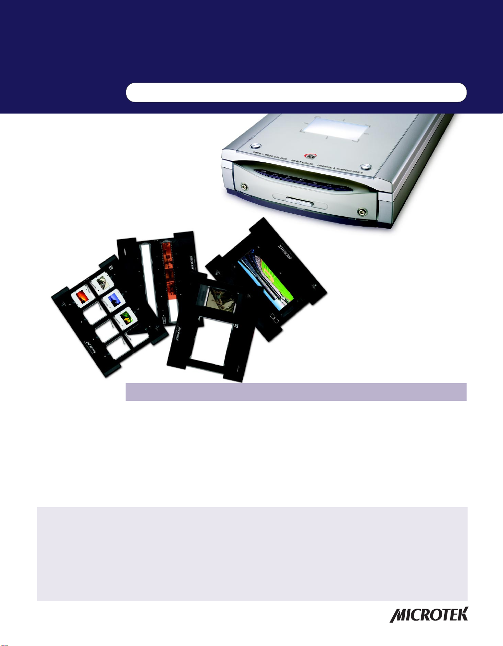
ScanMaker i700 features, scenarios, and information
Getting to Know Your ScanMaker i700
The ScanMaker i700 is a high-performance scanner that offers the exclusive
PictuRescueTM system with DIGIT AL ICETM T echnology and ColoRescueTM for
reconstruction and color restoration of photos and film. It features 9600 x 4800 dpi,
48-bit color, a legal size scan bed (8.5" x 14"), and 7 Smart-T ouch buttons on the front
panel to automate scanner functions (plus a convenient Power button). In addition,
the ScanMaker i700 offers robust film handling capabilities, including exclusive
EZ-LockTM Film Holders for more consistent film scans.
Contents
Getting to Know Your ScanMaker i70 0 ........................................................... 1
Features of the ScanMaker i700 ...................................................................... 2
Taking a Closer Look ........................................................................................ 3
Connecting to the FireWire Port .....................................................................4
How the Smart-Touch Scanner Buttons Work ..............................................6
DIGITAL ICE Technology .................................................................................. 7
Scanning Scenarios ......................................................................................... 8
Scanning Regular, Non-Damaged Photos (1) ............................................... 9
Scanning Regular, Non-Damaged Photos (2) ............................................. 10
Copyright © 2004 Microtek International, Inc. http://www.microtek.com
I49-003885 A, September 2004
Scanning Damaged Photos .......................................................................... 12
A. Using the DIGITAL ICE button ..................................................... 13
B. Scanning with Automatic Reconstruction ................................. 14
C. Scanning with Manual Reconstruction ....................................... 16
Scanning Regular, Non-Damaged Film ....................................................... 18
A. Scanning 35mm Filmstrips .......................................................... 19
B. Scanning 35mm Slides ................................................................. 21
C. Scanning 6 x 17 cm (120) Panoramic Film ................................... 22
D. Scanning 4 " x 5" / 6 x 9 cm (120) Film .......................................... 23
Scanning Damaged Film ............................................................................... 24
Specifications / System Requirements ........................................................ 26
Page 2

Features of the ScanMaker i700
The ScanMaker i700 comes with several important features, including the following:
• Microtek's PictuRescue system: This combined photo and film reconstruction and
restoration solution incorporates DIGIT AL ICE Technology and ColoRescue.
– With DIGITAL ICE Technology , the ScanMaker i700 can automatically map,
identify , and eliminate surface defects on both photos and film. Built into the
hardware and software, DIGIT AL ICE removes dust, scratches, rips, and tears,
reconstructing your damaged photos and film and restoring them to pristine,
near-original quality .
– With ColoRescue, the ScanMaker i700 restores faded colors in photos and film,
bringing hues back to their original luster and brilliance for more vibrant
images. ColoRescue's one-click, automatic color recovery process is simple
and straightforward, involving no learning curve or hassle.
• Seven Smart-Touch buttons: These buttons on the front panel of the scanner
provide you with a quick and easy way to launch frequently used scanner
functions. All it takes is one touch of a button — and you can launch the scanner
button's corresponding function. The seven Smart-Touch buttons include
DIGIT AL ICE, Scan, Copy , E-mail, OCR, Scan-to-W eb, and Custom.
• Integrated 4" x 9" transparency adapter: With a transparency adapter for scanning
slides, negatives, and transparencies built into the scanner lid, the ScanMaker
i700 improves your productivity and saves you money in having to acquire
additional film-scanning accessories. The built-in transparency adapter also
features the FilmView lightbox — a window with a light source that lets you
preview film or slides before they are loaded onto the scan bed for your scanning
convenience.
• Exclusive EZ-Lock Film Holders. These specially designed Microtek accessories
are designed to lock film securely in place. By loading the EZ-Lock Film Holder on
the scan bed before scanning film, you can ensure perfect alignment of your
images and achieve consistent scans.
2 ScanMaker i700 Supplement
Page 3
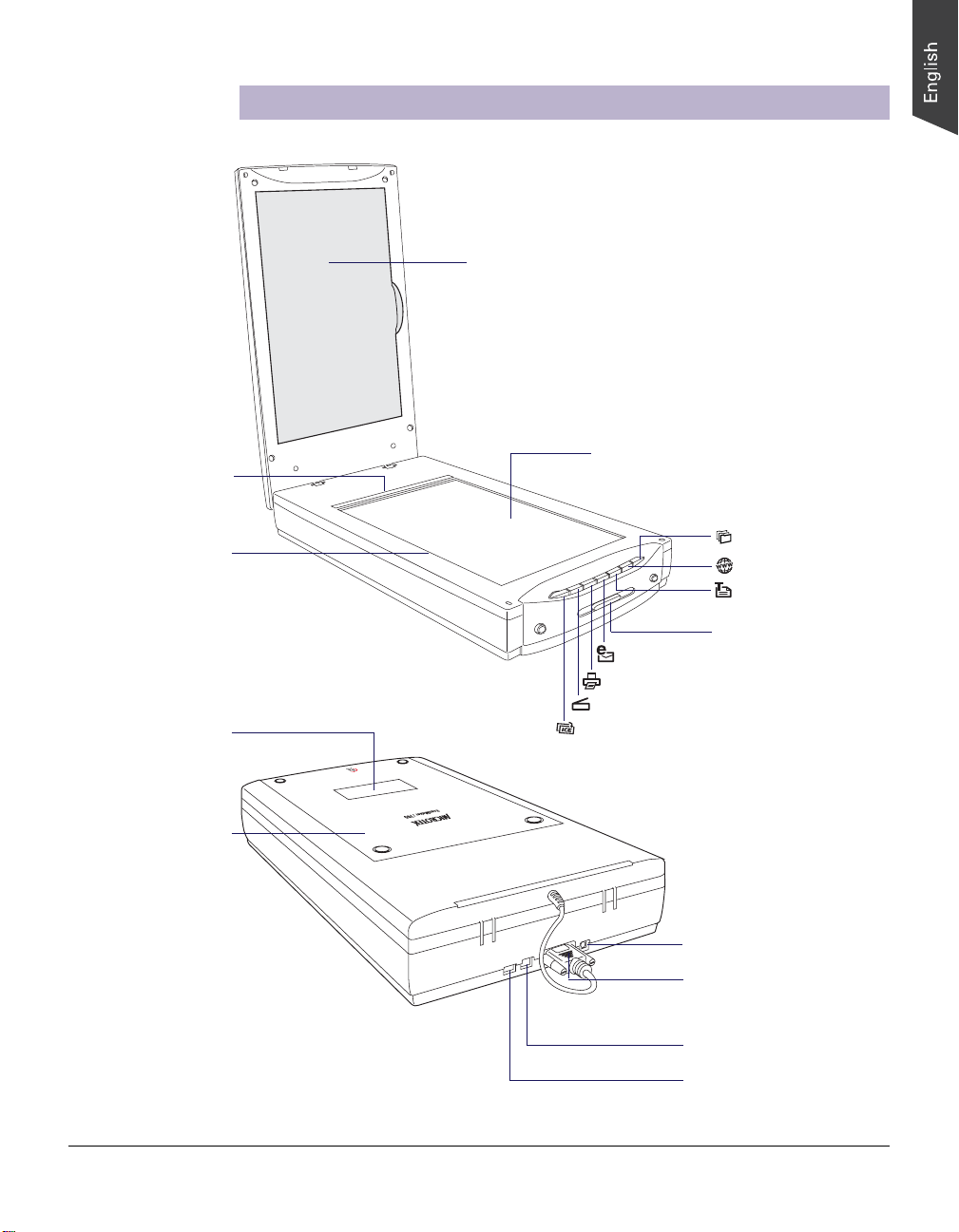
Horizontal ruler
(top ruler)
Taking a Closer Look
Black mat
Glass surface
Vertical ruler
FilmView
Scanner lid, with built-in
transparency adapter
Custom button
Scan-to-Web button
OCR button
Power button
E-mail button
Copy button
Scan button
DIGITAL ICE button
Power connector
Accessory port, with
connector of built-in
transparency adapter
securely connected
Hi-Speed USB port (1)
FireWire port (1)
ScanMaker i700 Supplement 3
Page 4
Connecting to the FireWire Port
The printed Start Here guide showed you how to connect your computer to the USB
port of the ScanMaker i700. Here, the Supplement shows you how to connect the
computer to the scanner's alternate FireWire port.
Prior to connection, check first to see if your computer system has a FireWire port. If
FireWire is present, connect the FireW ire cable to the FireW ire port. If your computer
does not have a FireWire port, install a FireW ire card to make use of the FireW ire port.
For details on how to install a FireWire card in your computer , refer to the
documentation that came with the FireWire card.
Note: Your ScanMaker i700 does not include a FireWire card in the package.
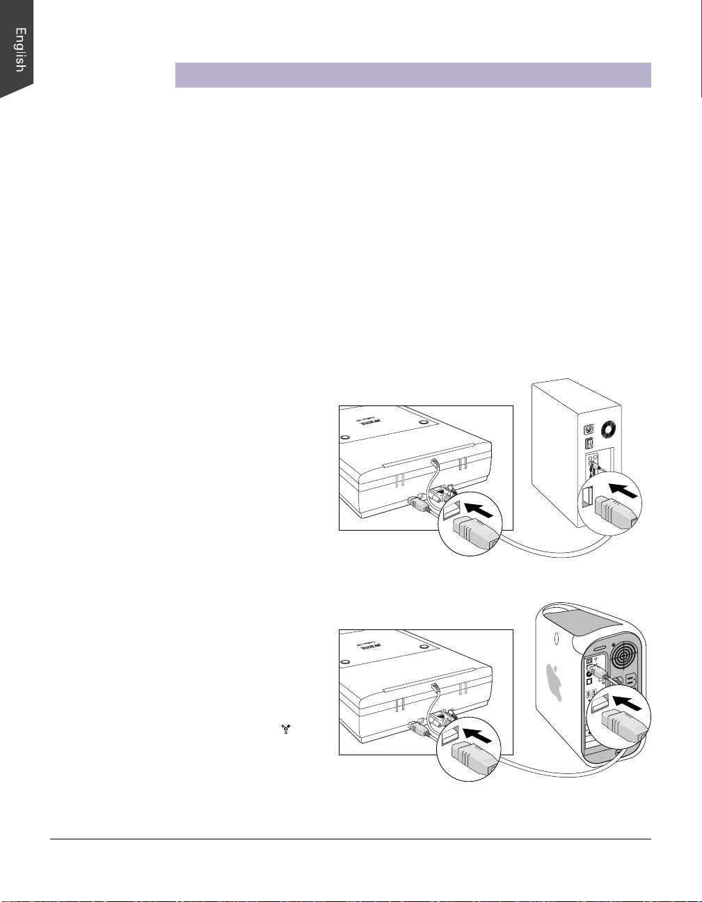
Follow the steps below to perform the FireWire connection:
1. Connect one end of the FireWire cable to your computer , and connect the other
end of the cable to the scanner’s FireW ire port.
(with a built-in FireWire port
or FireWire card installed)
(with a built-in FireWire port)
The latest Macintosh
computers (i.e., G3, G4, G5,
etc.) are equipped with a built-
in FireWire port, usually
labeled with the “ ” logo.
For PC users
For Mac users
4 ScanMaker i700 Supplement
Page 5
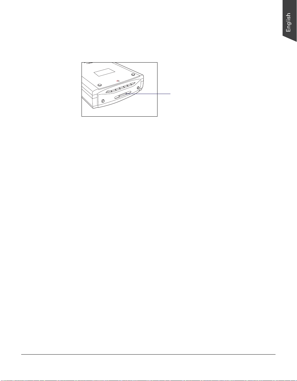
2. Press the Power button on the front panel of the scanner, and wait for the lights to
stop blinking and stay on steady.
The scanner will be detected by your system automatically.
Power button
ScanMaker i700 Supplement 5
Page 6

How the Smart-Touch Scanner Buttons Work
Note: The Smart-Touch buttons on the front panel of your scanner automate frequently
performed tasks, such as Scan to File, Scan to Printer, etc. For each scanner button,
the parameters governing the use of that button are defined or set through the
Microtek Scanner Configuration (MSC) utility. For instance, you can use the MSC to
define how many copies are to be printed of your scan every time you hit the “Copy”
button. To launch the MSC, double-click the MSC icon on your desktop. Please note
that you need to exit ScanWizard 5 before accessing the MSC utility.
The ScanMaker i700 is equipped with 7 Smart-T ouch buttons for easy access to
frequently used scanner functions. To carry out a specific task, simply press the
corresponding button on the scanner. The Smart-Touch buttons are:
1. DIGITAL ICE: Scans and removes dust, scratches, rips, and tears from damaged
photos. Take note that the DIGITAL ICE button works to reconstruct photos only.
T o reconstruct damaged film and transparencies, use the DIGIT AL ICE function in
the ScanWizard 5 software.
2. Scan: Captures images that can be automatically saved as files or sent to another
application for further processing.
3. Copy: Scans the image and sends it to your printer, transforming your scanner and
printer into a convenient copy station. Simply specify the number of copies you
want. To use the Copy button to print a stack of documents:
- Place the first page on the scanner glass surface.
- Press the Copy button to scan an image to a file, then automatically output to
your specified printer.
- Load the next page and press the Copy button again. The scanner works in
similar fashion to your printer, printing documents one after another with no
interruptions.
4. E-mail: Scans the image and delivers it directly to your e-mail editor.
5. OCR: Performs OCR (Optical Character Recognition) of a document and converts
it to a fully editable digital file. Saves time from retyping documents into your
word processor.
6. Scan-to-Web: Scans the image and posts it onto a photo-sharing website.
7. Custom: Customizes the Custom button to perform four of the most commonly
used functions, including:
- Power Saving: Turns the scanner lamp ON or OFF to save power and lamp life.
- Scan: Defines another button to be a second “Scan” button. Use this if you need
a second “Scan” button with different parameters from the first Scan button.
- Fax: Launches a fax driver installed on your computer.
- Launch Application: Defines an application to be launched.
6 ScanMaker i700 Supplement
Page 7

DIGITAL ICE Technology
DIGITAL ICE is an advanced technology that reconstructs damaged photos and film
during the scanning process, transforming the traditional photo or film restoration
process into one that is automatic, fast, and economical. Unlike software-only
correction, DIGIT AL ICE is built into your Microtek scanner hardware, providing a
seamless reconstruction process that brings damaged photos and film back to nearoriginal condition.
The Reconstruction Process
DIGIT AL ICE creates a defect map to identify the precise locations of physical
defects or visual “noise” on the print being scanned. The scanner's differential
shadowing technology and proprietary software algorithms then quickly and
automatically eliminate the unwanted defects.
In addition, Microtek has developed a unique Image Registration Technology that is
also built into your scanner to ensure precise color registration and superior image
quality. Because two scanning passes and two lamps are required in the use of
DIGIT AL ICE, precise registration is crucial in order to produce a perfectly aligned
image from the twin scanning passes. Microtek's Image Registration Technology
ensures accurate movement of the scanner mechanism, so that the mechanical steps
during the scanning process are registered with the ultra-fine precision needed for
superior, accurate scans.
Using Applicable Scan Materials
DIGIT AL ICE is used in the ScanMaker i700 to reconstruct damaged photos and film.
It is not designed to be used for printed materials from newspapers and magazines, or
printouts from inkjet/laser printers.
Processing Time
The use of DIGIT AL ICE requires two scanning passes to create an accurate defect
map through which image “noise” is identified and eliminated. Thus, a longer
processing time can be expected. Other factors can affect processing time, including
the speed of your computer's processor, as well as RAM.
ScanMaker i700 Supplement 7
Page 8

Scanning Scenarios
The following pages provide various scenarios for scanning with the ScanMaker
i700, including the following:
• Scanning regular, non-damaged photos (1): This scenario can also be your first
scan in order to familiarize yourself with scanning basics. It makes use of the
Standard Control Panel in ScanWizard 5.
• Scanning regular, non-damaged photos (2): This scenario is similar to above but
uses the Advanced Control Panel in ScanWizard 5.
• Scanning damaged photos: This scenario utilizes DIGIT AL ICE for reconstructing
damaged photos. Three methods are available for launching this function:
through the DIGITAL ICE button on the front panel of the scanner; through the
Automatic Reconstruction option; and through the Manual Reconstruction
option. The last two methods are accessed through the Advanced Control Panel
in ScanWizard 5.
• Scanning regular, non-damaged film: This scenario utilizes the various EZ-Lock
Film Holders to scan a variety of film, slides, and transparencies. It makes use of
the Advanced Control Panel in ScanW izard 5.
• Scanning damaged film: This scenario utilizes DIGIT AL ICE for correcting flaws
that may be present in your slides, negatives, and transparencies. It makes use of
the Advanced Control Panel in ScanW izard 5
8 ScanMaker i700 Supplement
Page 9
Scanning Regular, Non-Damaged Photos (1)
This scenario uses the Standard Control Panel.
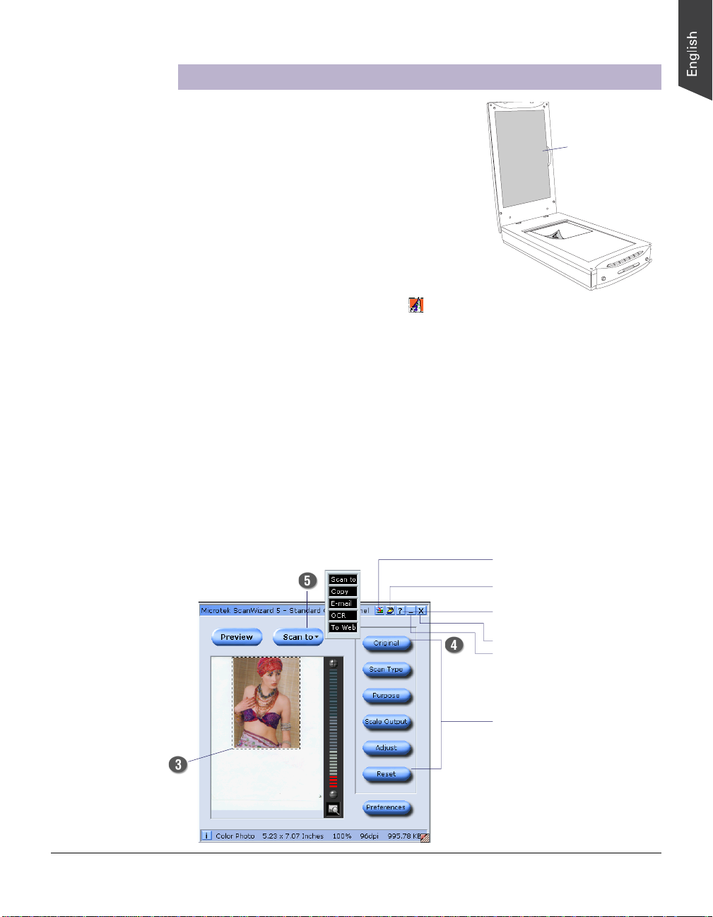
1. Raise the scanner lid, and place the photo to be
scanned face down on the scanner glass surface.
Position the top end of the photo towards the
back of the scanner.
Note: For the automatic cropping feature to
work correctly during the preview scan of your
photo, make sure the Black Mat is attached on
the scanner lid before you launch ScanWizard 5.
2. Double-click the ScanWizard 5 icon ( ) on your desktop to launch the
ScanWizard 5 S tandard Control Panel.
When ScanWizard 5 launches, it automatically performs a fast preview of the
material on your scanner glass surface and displays it in the preview area.
3 . In the preview window, you can resize the scan frame (floating dotted line) around
the image by dragging on the edge or corner of the scan frame to determine the
final size of the actual scan.
4. Click the Original button, then select Photo.
5. Click the Scan to button to scan the image.
The Black Mat
comes
preattached to
the scanner lid.
Resize the scan
frame to adjust
the actual size of
your scan
After the scan, the scanned and processed image can be saved as a file, opened
in an image-editing program, sent to a printer, attached in an e-mail, or uploaded
to a website.
• Allows you to switch to the
Advanced Control Panel
• Shows the scanner type,
model, and status
• Contains the built-in
ScanWizard 5 help
• Exits ScanWizard 5
• Minimizes ScanWizard 5
(Windows only)
Selections and options for
image settings
ScanMaker i700 Supplement 9
Page 10

Scanning Regular, Non-Damaged Photos (2)
This scenario makes use of the Advanced Control Panel.
1. Raise the scanner lid, and place the photo to be scanned face down on the
scanner glass surface. Position the top end of the photo towards the back of the
scanner. Make sure the Black Mat is attached on the scanner lid, then close the
scanner lid.
2. Double-click the ScanWizard 5 icon ( ) on your desktop to launch the
ScanWizard 5 S tandard Control Panel.
When ScanWizard 5 launches, it automatically performs a fast preview of the
material on your scanner glass surface and displays it in the preview area.
3 . Click the Switch icon ( ) on the right corner of the Standard Control Panel to
switch to the Advanced Control Panel.
4 . Click the Overview button to perform a preliminary view of the entire image. When
done, you will see an image appear in the preview window.
5 . In the preview window, you can resize the scan frame (floating dotted line) around
the image by dragging on the edge or corner of the scan frame to determine the
final size of the actual scan.
6. Specify your scanning requirements in the Settings window.
7 . If necessary , adjust image quality using the image corrections tools (White/Black
Points, T one Curve, Brightness/Contrast, Color Correction, Filter, and Descreen).
8. If the colors in your photo are faded and need restoring, check the “Automatic
Color Restoration” box in the Settings window.
9. Click the Scan to button to scan the image.
Depending on your selection, the scanned and processed image can be saved to
a file, opened in an image-editing program, sent to a printer, attached in an e-mail,
or uploaded to a website.
10 ScanMaker i700 Supplement
Page 11

ScanMaker i700 Supplement 11
Page 12

Scanning Damaged Photos
T o reconstruct damaged photos with DIGIT AL ICE, three methods are available:
through the DIGITAL ICE button on the front panel of the scanner; through the
Automatic Reconstruction option; and through the Manual Reconstruction option.
A. Using the DIGITAL ICE button
1. Raise the scanner lid, then place the damaged photo to be scanned face down on
the scanner glass surface. Center the top of the photo along the horizontal ruler
towards the back of the scanner.
Note: Make sure the Black Mat is attached to
Black Mat
the scanner lid. This will ensure that uneven
photos lay as flat as possible, which will
enhance the accuracy of detecting surface
damage on photos.
2 . Press the DIGIT AL ICE button on your
scanner. This will automatically scan,
detect and remove surface defects on
your photos. The saved image is stored
in your local disk and also appear as a
shortcut under the My Images folder on
your desktop.
12 ScanMaker i700 Supplement
Direction of
carriage motion
DIGITAL ICE
Note: If the creases in your photo lie
parallel to the direction of the carriage
motion, the creases may not be detected
by the scanner. To fix this problem,
position your photo slightly skewed
(min. 10°, max. 45°), so that none of the
creases are parallel to the direction of
the carriage movement.
Page 13

Customizing the DIGITAL ICE button
The DIGITAL ICE button can be customized to suit your preferences, so that you
can specify settings that, for instance, indicate the strength of your DIGIT AL ICE
setting, the location of files to be saved, etc. Pressing the DIGIT AL ICE button after
customizing will invoke these settings repeatedly until you change your
preferences.
To customize the DIGITAL ICE button:
1. Double-click the Microtek Scanner
Configuration icon ( ) on your desktop to
launch the MSC utility.
2 . When MSC is launched, click the “ICE” tab on
the top to view or customize the DIGIT AL ICE
button to your need.
3. Choose your settings, then click the OK
button to save the settings and to exit the
MSC utility .
ScanMaker i700 Supplement 13
Page 14

B. Scanning with Automatic Reconstruction
With the Automatic Reconstruction option, DIGITAL ICE scans for defects and
applies an algorithm calculated automatically for optimal photo reconstruction and
correction.
1. Raise the scanner lid, then place the damaged photo to be scanned face down on
the scanner glass surface. Center the top of the photo along the horizontal ruler
towards the back of the scanner. Make sure the Black Mat is attached on the
scanner lid, then close the scanner lid.
2. Double-click the ScanWizard 5 icon ( ) on your desktop to launch the
ScanWizard 5 S tandard Control Panel.
3 . Click the Switch icon ( ) on the right corner of the Standard Control Panel to
switch to the Advanced Control Panel.
4 . Click the Overview button to perform a preliminary view of the entire image. When
done, you will see an image appear in the preview window.
5 . In the preview window, you can resize the scan frame (floating dotted line) around
the image by dragging on the edge or corner of the scan frame to determine the
final size of the actual scan.
6 . Specify your scanning requirements in the Settings window when the ScanWizard
5 Advanced Control Panel appears.
a) Select RGB Colors/RGB Color (48-bit) or Grayscale/Grayscale (16-bit) in the
Type pull-down menu as your image output type.
b) Select a desired resolution in the Resolution pull-down menu for your image
output resolution. The recommended resolution for DIGIT AL ICE for photos is
600 dpi, and take note that the use of DIGIT AL ICE will require additional time
in processing compared to regular scanning.
c) Adjust the scan frame settings if necessary.
7 . If necessary , adjust image quality using the image corrections tools (White/Black
Points, T one Curve, Brightness/Contrast, Color Correction, Filter, and Descreen).
Important: The Descreen setting in the Settings window should be “None.”
Otherwise the “DIGIT AL ICE” option in the next step will be dimmed and will not
be available for selection.
8. In the Settings window, choose “Automatic
Reconstruction” from the DIGIT AL ICE
options menu.
14 ScanMaker i700 Supplement
Page 15

Before After
9. If the colors in your photo are faded and need restoring, check the “Automatic
Color Restoration” box in the Settings window .
10. Click the Scan to button to scan the image. After the scan, defects such as dust,
scratches, cracks, creases, rips, folds and other artifacts on the photo are all
removed, resulting in an improved image.
Depending on your selection, the scanned and processed image can be saved to a
file, opened in an image-editing program, sent to a printer, attached in an e-mail, or
uploaded to a website.
ScanMaker i700 Supplement 15
Page 16
C. Scanning with Manual Reconstruction
With the Manual Reconstruction option, the damaged photo is restored through the
use of manual settings and procedures. This is a more complicated and involved
procedure, but Manual Reconstruction gives you greater control in fine-tuning the
degree of correction you would like. It also allows you to include areas of damage
that may not be “seen” through the automatic reconstruction process but which you
can detect with the naked eye or which you know are there.
1. Follow the procedures (steps 1 through 7) for scanning damaged photos in
previous section “Scanning in Automatic Reconstruction” to carry out scanning.
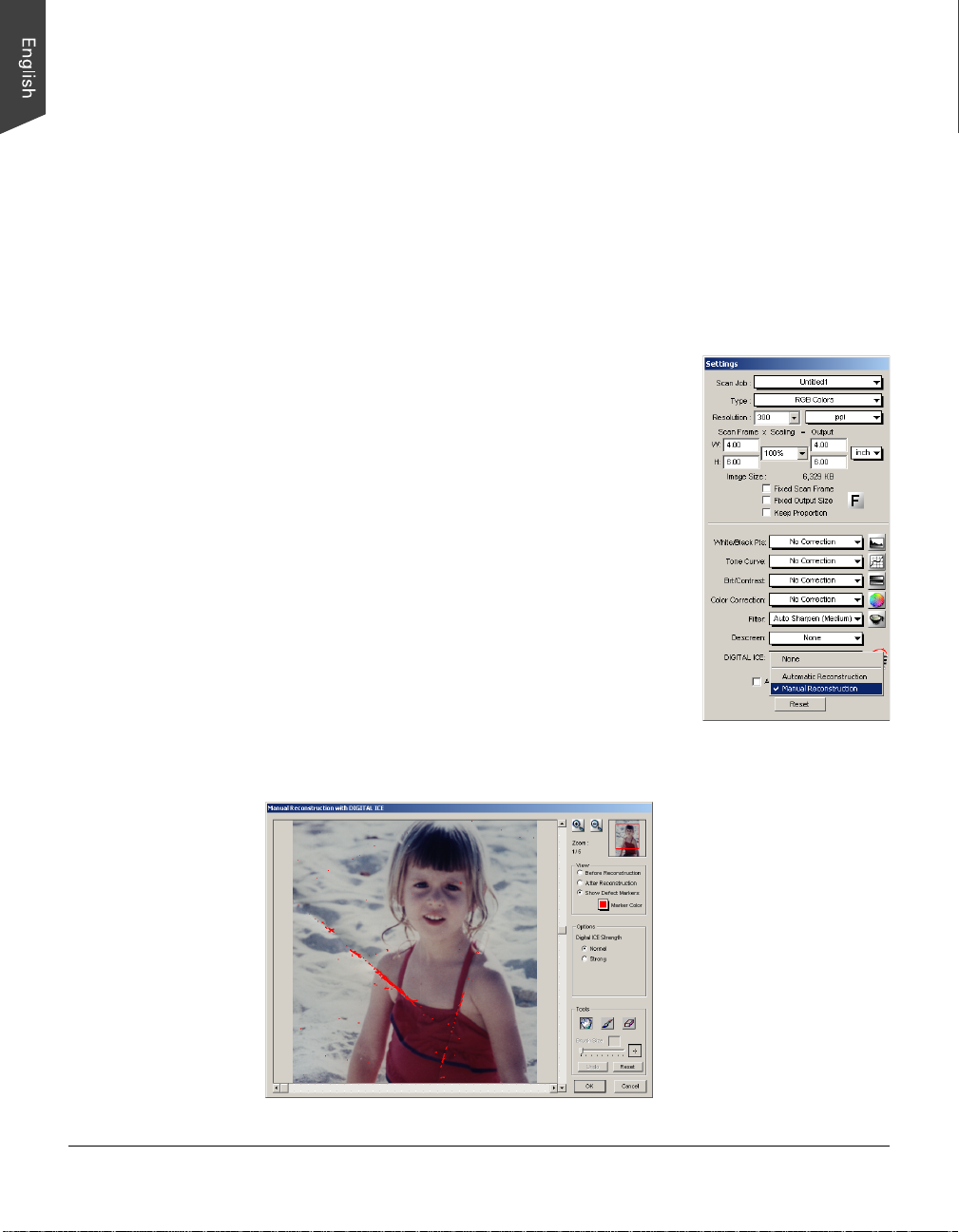
2. In the Settings window, choose “Manual
Reconstruction” from the DIGIT AL ICE options menu.
A message appears, indicating that the correction of
defects will be implemented according to manual
settings after the image is scanned.
3 . In the Preview window, click the “Scan To” button to
perform scanning.
4. When the “Scan To” button is pressed, the Save As
dialog box appears. Specify the necessary settings for
the output image, then click “Save”.
At this point, scanning of the damaged photo begins
and a defect map is created in the process. This may
take a few minutes.
A “Manual Reconstruction with DIGITAL ICE”
window then appears, with a preview of the scanned
image and corresponding function tools.
16 ScanMaker i700 Supplement
Page 17

When the “Manual Reconstruction with DIGIT AL ICE” window is launched the
first time, the scanned image appears with defect markers. This option is checked
automatically. You can change the color of the defect marker to get a better view
of the defects by clicking the Marker Color icon.
5 . Choose the “DIGIT AL ICE Strength” option that works best for you for repairing
surface defects. Select from Normal or Strong.
6. If necessary, use the Brush tool to add defects which cannot be detected by the
scanner after the scan but are otherwise visible in the damaged print and which
you want to remove from the image.
7. If necessary, use the Eraser tool to remove any false or unwanted defect, which
can be detected by the scanner after the scan.
8. Check the “After Reconstruction” option, the defect correction applies to the
Defect Map area in real time.
Before
After
9 . Click the “OK” button to perform the defect fixing according to the settings
specified under this window; the scanned image is saved with the settings for
defect fixing.
ScanMaker i700 Supplement 17
Page 18

Scanning Regular, Non-Damaged Film
T o scan film, use the EZ-Lock Film Holders included with your ScanMaker i700. The
EZ-Lock Film Holders for the ScanMaker i700 include holders for 35mm slides, 35mm
filmstrips, 6 x 17 cm (120) panoramic film, and 4" x 5" / 6 x 9 cm film. The film holders
not only ensure precise alignment of film and consistent scans, but also perform
automatic cropping when they scan various sizes of film. T o scan various film sizes,
use the holder that correctly matches the film type to be scanned.
Removing the Black Mat
The Black Mat is designed to work with
reflective originals such as photos and printed
matter. It is not designed to work with slides,
negatives, and transparencies. During film
scanning, the Black Mat should be removed to
reveal the light source in the scanner for film.
T o remove the Black Mat: Raise the scanner
lid, and push the Black Mat to the side (1 in
diagram) to remove it from the scanner lid
(2 in diagram).
Using the FilmView
The FilmView , a clear window located on the top
of the built-in transparency adapter , is designed
for previewing film or slides before they are
loaded onto the scanner bed. The FilmV iew adds
to your convenience in the selection and
verification of slides or film for scanning.
T o select the film you wish to scan, make sure
that the FilmV iew is on, then place the film you
wish to scan on the top of the built-in
transparency adapter, using the light source provided by the FilmView to preview your
film.
Note: If the light source of the FilmView is in the “Sleep” mode, press the scanner's
Custom button to exit or halt sleep mode. For more details on the Custom button,
see the online help of the Microtek Scanner Configuration (MSC).
Notes on auto-crop scanning
For the scanner to perform automatic cropping during scanning, the following conditions below should all be met:
• Your computer's operating system should be either Windows or Mac OS X
• The EZ-Lock Film Holder is correctly aligned on the scan bed
• The scan material is Positive or Negative Film, with the slide or filmstrip to be scanned is correctly loaded on the EZ-Lock
Film Holder
• In the Scan Job Queue window of ScanWizard 5, the “Multiple Auto-crop for EZ-Lock Film Holder” option is checked.
18 ScanMaker i700 Supplement
Page 19

To make sure the auto
multiframe cropping
feature performs
correctly, align the
holder’s front edges
flush against the top
ruler of the scanner.
A. Scanning 35mm Filmstrips
T o scan 35mm filmstrips, use the EZ-Lock 35mm Filmstrip Holder which can
simultaneously hold two strips of 6 frames each, or a total of 12 frames.
1 . Load the filmstrip face down inside the holder. Slide the filmstrip along the slots of
the holder until the filmstrip is fully loaded.
Align the frame-by-frame partition with
the dash marks on the film guide.
For a short filmstrip, make sure the
film edge is close to the open end
of the slot.
2 . Raise the scanner lid, then place the holder with the loaded film on the scan bed.
The calibration window on the glass
surface should be kept clear and free from
any obstruction during scanning.
3. Gently lower the scanner lid down onto the scan bed; the lid should be able to
close completely. Do not use the Black Mat.
4. Double-click the ScanWizard 5 icon ( ) on your desktop to launch the
ScanWizard 5 Standard Control Panel, then click the Switch icon ( ) on the right
corner of the Standard Control Panel to switch to the Advanced Control Panel.
5 . Click the Scan Material button ( )
in the Preview window of
ScanWizard 5, and choose
Negative Film. For Mac OS X,
select Negative from the Scan
Material drop-down menu.
ScanMaker i700 Supplement 19
Page 20
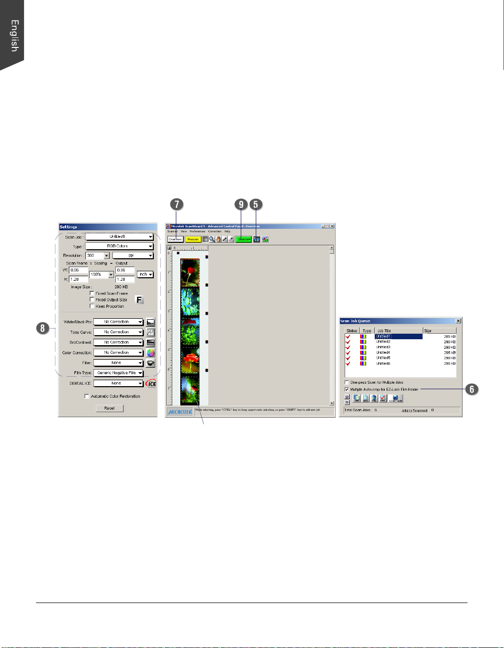
6 . Check the “Multiple Auto-crop for EZ Lock Film Holder” option in the Scan Job
Queue window.
7 . Click the Overview button in the Preview window to auto-crop and perform a
preview of the film loaded onto the scanner.
When done, you will see multiple scan frames that have been automatically
cropped in the preview window. Multiple job titles will appear in the Scan Job
Queue window, numbered sequentially and all marked by a “Check” that indicates
the jobs are ready to be scanned. The scan area (framed in dotted lines) will
appear in the Preview window .
8. Specify your scanning parameters for each scan job in the Settings window.
9 . Click the Scan to button in the Preview window to scan all the checked jobs.
10. After the scan, the scanned and processed images can be saved as several files,
opened in an image-editing program, sent to a printer, attached in an e-mail, or
uploaded to a website.
20 ScanMaker i700 Supplement
Auto-cropped images are
framed in dotted line.
Page 21

To make sure the auto
multiframe cropping
feature performs
correctly, align the
holder’s front edges
flush against the top
ruler of the scanner.
B. Scanning 35mm Slides
T o scan 35mm slides, use the EZ-Lock 35mm Slide Holder which can simultaneously
hold up to 8 mounted 35mm slides at a time.
1 . Flip the 35mm slides face down
and place them into the holder.
2 . Raise the scanner lid, then place the holder with the loaded film on the scan bed.
1
5
6
2
3
7
8
4
The calibration window on
the glass surface should be
kept clear and free from any
obstruction during scanning.
3 . Follow the procedures (steps 3 through 10) for scanning 35mm filmstrips to carry
out scanning.
Before performing step 5, click the Scan Material icon, and choose “Positive
Film” from the Scan Material drop-down menu. For Mac OS X, select “Positive.”
ScanMaker i700 Supplement 21
Page 22

C. Scanning 6 x 17 cm (120) Panoramic Film
T o scan 6 x 17 cm (120) Panoramic Film, use the EZ-Lock 6 x 17 cm (120) Panoramic
Film Holder which can hold 1 piece of 120 panoramic film or a variety of variouslysized film, such as 4 pieces of 6 x 4.5 cm film, or 2 pieces each of 6 x 6 cm film, 6 x 7 cm
film, and 6 x 9 cm film.
1 . Load the film face down inside the holder.
a) Push on the side to open the lid.
b) Place the film face down into the holder.
c) Pull down the side to close the lid.
2 . Raise the scanner lid, then place the holder with the loaded film on the scan bed.
To make sure the auto
multiframe cropping
feature performs
correctly, align the
holder’s front edges
flush against the top
ruler of the scanner.
3 . Follow the procedures (steps 3 through 10) for scanning 35mm filmstrips to carry
out scanning.
22 ScanMaker i700 Supplement
The calibration window on the
glass surface should be kept
clear and free from any
obstruction during scanning.
Page 23

To make sure the auto
multiframe cropping
feature performs
correctly, align the
holder’s front edges
flush against the top
ruler of the scanner.
D. Scanning 4" x 5" / 6 x 9 cm (120) Film
To scan 4" x 5" or 6 x 9 cm (120) film, use the EZ-Lock 4" x 5" / 6 x 9 cm (120) Film
Holder which can hold 1 piece of 4" x 5" film, 2 pieces of 6 x 4.5 cm, or 1 piece each at
a time of 6 x 6 cm film, 6 x 7 cm film, and 6 x 9 cm film.
1 . Load the film face down inside the
holder. Slide the film along the slots of
the holder until the film is fully loaded.
2 . Raise the scanner lid, then place the holder with the loaded film on the scan bed.
3 . Follow the procedures (steps 3 through 10) for scanning 35mm filmstrips to carry
out scanning.
The calibration window on the
glass surface should be kept clear
and free from any obstruction
during scanning.
ScanMaker i700 Supplement 23
Page 24

Scanning Damaged Film
1 . Raise the scanner lid, then follow the
procedures in the previous section to load
the film that you wish to scan and to place
the EZ-Lock Film Holder on the scan bed.
Gently lower the scanner lid down onto the
scan bed. Do not use the Black Mat.
2 . Double-click the ScanWizar d 5 icon ( ) on
your desktop to launch the ScanWizard 5
Standard Control Panel, then click the Switch icon ( )on the right corner of the
Standard Control Panel to switch to the Advanced Control Panel.
3 . In the Preview window of
ScanWizard 5, click the Scan
Material button or drop-down
menu. Choose Negative Film or
Negative for negatives; choose
Positive Film or Positive for
transparencies and slides,
depending on the film type you are using.
4 . In the Scan Job Queue window, check the “Multiple Auto-crop for EZ Lock Film
Holder” option.
5 . Click the Overview button to auto-crop and perform a preview of the film loaded
onto the scanner.
When done, you will see multiple scan frames that have been automatically
cropped in the preview window. Multiple job titles will appear in the Scan Job
Queue window, numbered sequentially and all marked by a “Check” that indicates
the jobs are ready to be scanned. The scan area (framed in dotted lines) will
appear in the Preview window.
6. Specify your scanning requirements for each scan job in the Settings window.
a) Select RGB Colors/RGB Color (48-bit) or Grayscale/Grayscale (16-bit) in the
Type pull-down menu as your image output type.
b) Select a desired resolution in the Resolution pull-down menu for your image
output resolution. The recommended resolution for DIGIT AL ICE is 1200 dpi,
and take note that using DIGIT AL ICE will require more time than regular
scanning.
c) Adjust the scan frame settings if necessary.
24 ScanMaker i700 Supplement
Page 25

7 . If necessary , adjust image quality using the image corrections tools (White/Black
Points, T one Curve, Brightness/Contrast, Color Correction, and Filter).
8 . Choose the “DIGITAL ICE” option that
works best for you. Select from None,
Normal, or Str ong . In Film mode, DIGITAL
ICE automatically removes surface defects
from your slides, negatives, and
transparencies.
9 . If the colors in your film sample are faded and need restoring, check the
“Automatic Color Restoration” box in the Settings window.
10. Click the Scan to button to scan the image. After the scan, defects such as dust,
scratches, cracks, creases, rips, folds and other artifacts on the original image are
all removed, resulting in an improved image.
Depending on your selection, the scanned and processed image can be saved to a
file, opened in an image-editing program, sent to a printer, attached in an e-mail, or
uploaded to a website.
Before
After
ScanMaker i700 Supplement 25
Page 26

Specifications
Scanning Modes Color, grayscale, and black-and-white in a single scanning
pass
True 48-bit color (approx. 281 x 1012 colors)
16-bit grayscale (approx. 65,536 shades of gray)
Scanning Area Reflective: 8.5" x 14" (216 mm x 356 mm)
Transparent: 4" x 9" (102 mm x 229 mm)
Resolution Optical: 9600 dpi x 4800 dpi
Interpolated: 65,535 dpi (PC); 32,767 dpi (Mac)
Interface Hi-Speed USB (USB 2.0) and FireWire (IEEE 1394)
Dimensions (L x W x H) 21.5" x 11.7" x 3.6" (545 mm x 297 mm x 92 mm)
Net Weight 11.9 lbs (5.4 kg)
Voltage AC 100V to 240V
1.2A Max; 47-63 Hz (Input)
15V/2.5A (Output)
Environment Operating T emperature: 50° F to 104° F (10° C to 40° C )
Power supply Manufacturer Model No. Voltage
(AC/DC adapter) F AI R WAY VE50-150A 100V to 240V
System Requirements
General Requirements
• CD-ROM drive (for installing software)
• Color display with 24-bit color output capability
• 128MB RAM (256MB or more to use DIGIT AL ICE T echnology)
PC and compatibles
• Pentium III PC or higher with USB, Hi-Speed USB (USB 2.0), or FireWire (IEEE
1394) port
• Microsoft Windows 98SE, Me, 2000 or XP
Macintosh
• iMac or Mac G3/G4/G5 with built-in USB port or FireWire port
• Mac OS 9.x, Mac OS X 10.2, 10.3 or later
Important
Specifications, bundles, and accessories are subject to change without notice.
26 ScanMaker i700 Supplement
Page 27

FCC Compliance Statement
This equipment (Model: MRS-9600FU2) has been tested and found to comply with
the limits for a Class B digital device, pursuant to Part 15 of the FCC rules. These
limits are designed to provide reasonable protection against harmful interference in a
residential installation. This equipment generates, uses and can radiate radio
frequency energy and, if not installed and used in accordance with the instructions,
may cause harmful interference to radio communications. However, there is no
guarantee that interference will not occur in a particular installation. If this equipment
does cause harmful interference to radio or television reception, which can be
determined by turning the equipment off and on, the user is encouraged to try to
correct the interference by one or more of the following measures:
• Reorient or relocate the receiving antenna.
• Increase the separation between the equipment and receiver.
• Connect the equipment into an outlet on a circuit different from that to which the
receiver is connected.
• Consult the dealer or an experienced radio/TV technician for help.
Note: A shielded Hi-Speed USB interface cable with ferrite core installed on the
scanner connector and must be used with this equipment.
Caution: Changes or modifications not expressly approved by the manufacturer
responsible for compliance could void the user's authority to operate the equipment.
This device complies with Part 15 of the FCC Rules. Operation is subject to the
following two conditions: (1) This device may not cause harmful interference, and (2)
this device must accept any interference received, including interference that may
cause undesired operation.
Responsible Party: Loi Han
Microtek Lab, Inc.
16941 Keegan A venue
Carson, CA 90746
USA
Phone: 310-687-5800
Fax: 310-687-5950
ScanMaker i700 Supplement 27
 Loading...