

Page 1
IC Equipment
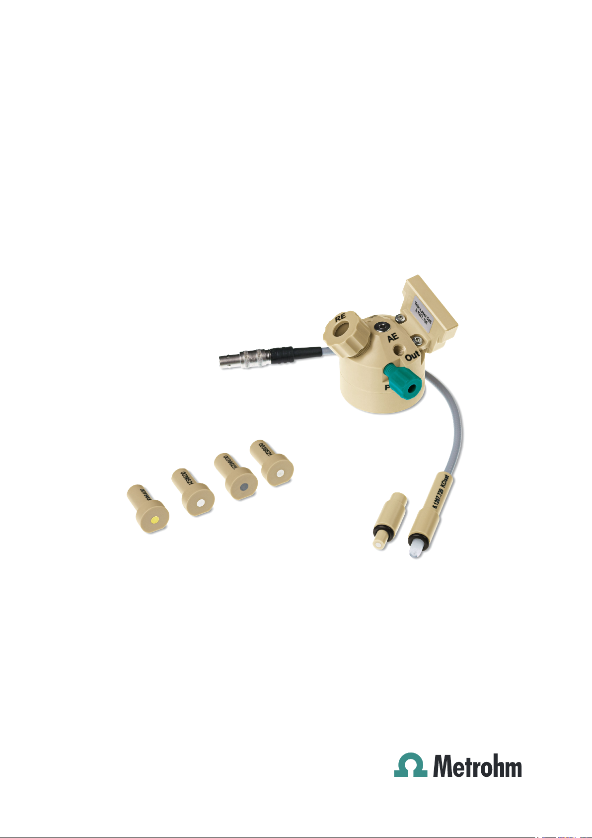
Thin-Layer cell
Manual
8.110.8020EN
Page 2

Page 3

Metrohm AG
CH-9100 Herisau
Switzerland
Phone +41 71 353 85 85
Fax +41 71 353 89 01
info@metrohm.com
www.metrohm.com
IC Equipment
Thin-Layer cell
6.5337.200
8.110.8020EN
Manual
06.2012 zst
Page 4

Teachware
Metrohm AG
CH-9100 Herisau
teachware@metrohm.com
This documentation is protected by copyright. All rights reserved.
Although all the information given in this documentation has been
checked with great care, errors cannot be entirely excluded. Should you
notice any mistakes please send us your comments using the address
given above.
Documentation in additional languages can be found on
http://documents.metrohm.com.
Page 5

■■■■■■■■■■■■■■■■■■■■■■
Table of contents
1 Introduction 1
1.1 Description ............................................................................ 1
1.2 About the documentation ................................................... 1
1.2.1 Content and scope .................................................................. 1
1.2.2 Symbols and conventions ........................................................ 2
2 Overview 3
3 Installation 4
3.1 Inserting the working electrode .......................................... 4
3.2 Inserting the reference electrode ........................................ 5
3.3 Connecting the detector capillaries .................................... 8
3.4 Connecting the electrode connection cables ................... 10
Table of contents
4 Start-up 12
5 Operation and maintenance 13
5.1 Operation ............................................................................ 13
5.2 Maintenance ....................................................................... 13
5.2.1 Replacing the working electrode ............................................ 13
5.2.2 Replacing the reference electrode .......................................... 14
5.2.3 Replacing the spacer .............................................................. 15
5.2.4 Cleaning the measuring cell ................................................... 17
6 Technical specifications 20
7 Accessories 21
7.1 IC equipment Thin-Layer cell: without electrodes ........... 21
Index 23
IC Equipment Thin-Layer cell
■■■■■■■■
III
Page 6

Table of figures
Table of figures
Figure 1 Thin-Layer cell – Parts and connectors ............................................... 3
Figure 2 Ag/AgCl reference electrode (6.1257.720) ......................................... 6
Figure 3 Disassembling the measuring cell .................................................... 16
■■■■■■■■■■■■■■■■■■■■■■
■■■■■■■■
IV
IC Equipment Thin-Layer cell
Page 7

■■■■■■■■■■■■■■■■■■■■■■
1 Introduction
1.1 Description
The Thin-Layer cell is used for amperometric detection with the Amperometric Detector. The Thin-Layer cell especially qualifies for applications
with double detector mode, e. g. if an amperometric detection is followed
by another detection technique.
In the Thin-Layer cell, the sample flows in a thin layer between the auxiliary electrode and the working electrode and is analyzed with amperometric methods.
1.2 About the documentation
Caution
1 Introduction
Please read through this documentation carefully before putting the
measuring cell into operation. The documentation contains information
and warnings which the user must follow in order to ensure safe operation of the instrument.
1.2.1 Content and scope
Content of this manual
This manual describes:
■ The insertion of the working electrode in the Thin-Layer cell.
■ The insertion of the reference electrode in the Thin-Layer cell.
■ The connection of the capillaries and the electrode cables.
■ All maintenance work that can be carried out by the user.
■ The technical specifications of the Thin-Layer cell.
■ The supplied and the optional accessories.
Further information
Detailed information concerning the insertion of the measuring cell into
the detector can be found in the manuals for the amperometric detector.
Information on the utilization, care and maintenance of the working electrodes and reference electrodes can be found in the leaflets which are
enclosed with the electrodes.
IC Equipment Thin-Layer cell
■■■■■■■■
1
Page 8
1.2 About the documentation
1.2.2 Symbols and conventions
The following symbols and formatting may appear in this documentation:
Method Dialog text, parameter in the software
File ▶ New Menu or menu item
[Next] Button or key
■■■■■■■■■■■■■■■■■■■■■■
Cross-reference to figure legend
The first number refers to the figure number, the second to the instrument part in the figure.
Instruction step
Carry out these steps in the sequence shown.
Warning
This symbol draws attention to a possible life hazard
or risk of injury.
Warning
This symbol draws attention to a possible hazard due
to electrical current.
Warning
This symbol draws attention to a possible hazard due
to heat or hot instrument parts.
Warning
This symbol draws attention to a possible biological
hazard.
Caution
This symbol draws attention to a possible damage of
instruments or instrument parts.
Note
This symbol marks additional information and tips.
■■■■■■■■
2
IC Equipment Thin-Layer cell
Page 9
■■■■■■■■■■■■■■■■■■■■■■
6
4
3
1
7
8
9
10
5
2
2 Overview
2 Overview
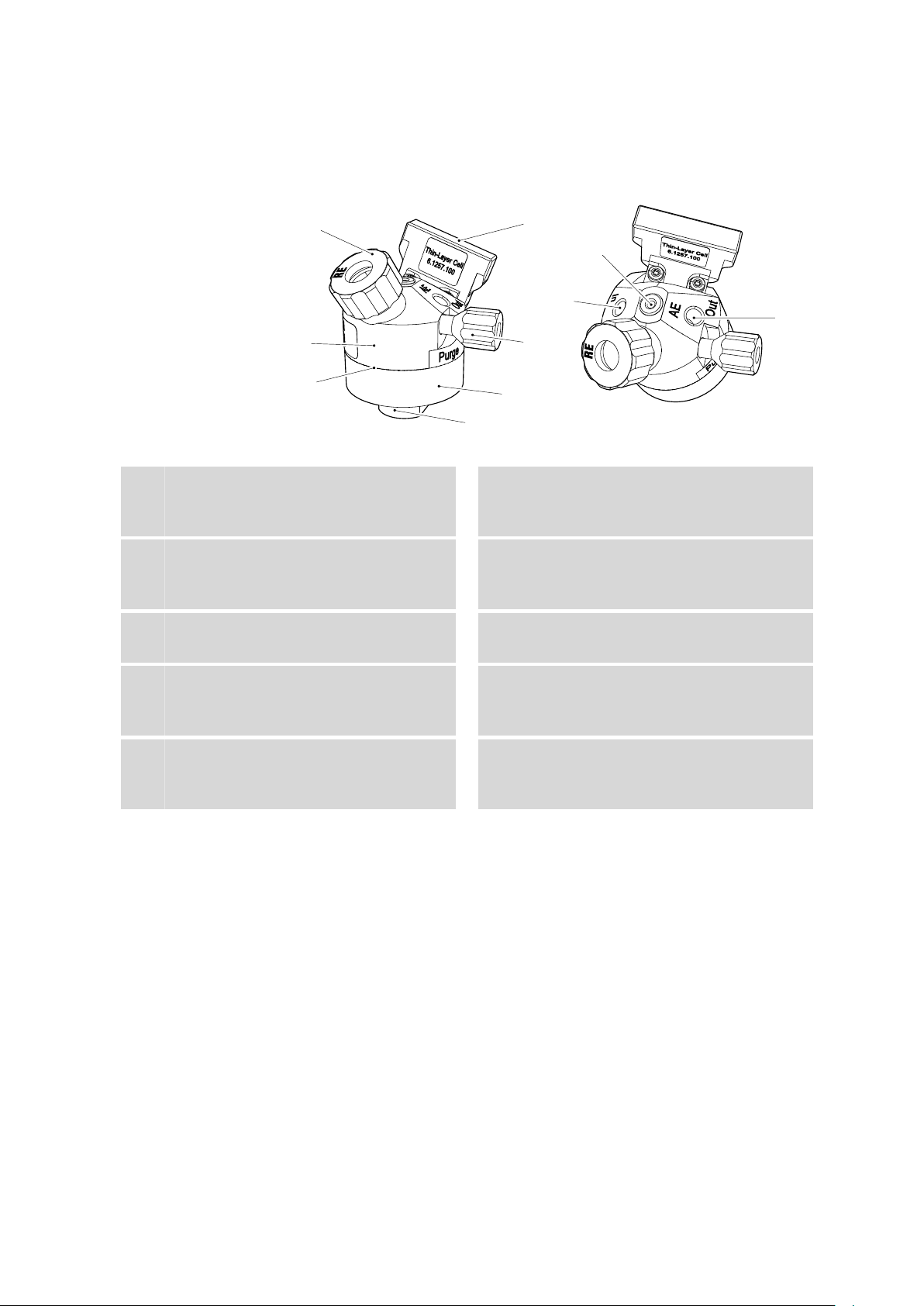
Figure 1 Thin-Layer cell – Parts and connectors
Fastening screw
1
For fixing the reference electrode in place.
Labeled with RE.
Spacer
3
Base part
5
Chip
7
With intelligence. For inserting the measuring cell into the detector.
Electrode cable connection socket
9
For the auxiliary electrode cable. Labeled
with AE.
Measuring part
2
With built-in auxiliary electrode.
Pressure screw
4
For fixing the working electrode (WE) in
place.
Stopper
6
For sealing the deaeration opening.
Eluent input
8
Labeled with In.
Eluent output
10
Labeled with Out.
IC Equipment Thin-Layer cell
■■■■■■■■
3
Page 10

3.1 Inserting the working electrode
3 Installation
Caution
Never switch on the measuring cell..
■ ... if it is not simultaneously being rinsed by a conductive eluent; or
■ ... if the electrode cables are not completely connected.
3.1 Inserting the working electrode
The measuring cell is supplied without electrodes. The working electrode
must be ordered separately.
Insert the working electrode as follows:
■■■■■■■■■■■■■■■■■■■■■■
Inserting the working electrode
Unscrew the pressure screw on the base part of the cell and remove
1
it.
Insert the working electrode in the opening. The working electrode is
2
formed in such a way that it can be inserted into the measuring cell
in only one position.
Slide the pressure screw over the working electrode and screw it
3
tightly.
■■■■■■■■
4
IC Equipment Thin-Layer cell
Page 11

■■■■■■■■■■■■■■■■■■■■■■
3.2 Inserting the reference electrode
The measuring cell is supplied without electrodes. Reference electrodes
must be ordered separately.
Insert the reference electrode as follows:
Inserting the reference electrode
The reference electrode itself and one sealing ring are contained in the
packaging for the reference electrode.
Slide the sealing ring over the reference electrode.
1
3 Installation
Unscrew the fastening screw on the RE connector and remove it.
2
Insert the reference electrode into the opening with the flat side fac-
3
ing downward.
Retighten the fastening screw.
4
Special case: Ag/AgCl reference electrode
The Ag/AgCl reference electrode (6.1257.720) is, in contrast to the other
reference electrodes, permanently connected to the reference electrode
cable.
IC Equipment Thin-Layer cell
■■■■■■■■
5
Page 12

3.2 Inserting the reference electrode
1
2
4
5
3
Figure 2 Ag/AgCl reference electrode (6.1257.720)
■■■■■■■■■■■■■■■■■■■■■■
Plug
1
Sealing screw
3
For sealing the storage vessel.
Storage vessel
5
For storing the Ag/AgCl reference electrode.
Insert the reference electrode as follows:
Inserting the Ag/AgCl reference electrode
Take the Ag/AgCl reference electrode out of the storage vessel. Pull
1
the sealing screw of the storage vessel over the plug and reseal the
storage vessel with it.
Reference electrode cable
2
Permanently mounted on the reference electrode.
Reference electrode
4
6
■■■■■■■■
IC Equipment Thin-Layer cell
Page 13

■■■■■■■■■■■■■■■■■■■■■■
3 Installation
Unscrew the fastening screw from the reference electrode holder.
2
Push the fastening screw over the cable of the Ag/AgCl reference
electrode.
Check whether the sealing ring is seated on the reference electrode
3
and insert the reference electrode into the reference electrode
holder.
Tighten the reference electrode to the reference electrode holder
4
with the fastening screw.
Further information regarding the correct handling of the Ag/AgCl reference electrode can be found in the leaflet for the Ag/AgCl reference electrode.
IC Equipment Thin-Layer cell
■■■■■■■■
7
Page 14

3.3 Connecting the detector capillaries
3.3 Connecting the detector capillaries
The amperometric detector has a preheating capillary in its interior that
ensures that the eluent flows through the measuring cell at a constant
temperature.
Connecting the preheating capillary is optional. If the ambient conditions
are optimal or if the eluent in the column is heated, then the measuring
results can be sufficiently accurate, even without the use of the preheating
capillary.
Caution
The preheating capillary may not be used with readily flammable liquids!
In the event of a leak, the fluid might evaporate and ignite in the heating area.
■■■■■■■■■■■■■■■■■■■■■■
If the preheating capillary is used, proceed as follows:
Connecting capillaries to the measuring cell
1
Connect the preheating capillary
Note
This preheating capillary must be tested with the IC instrument the
first time the detector is put into operation, see Chapter "Start-up"
in the manual for the detector.
■ Use a pressure screw (6.2744.014) to connect the detector input
capillary to the connector Eluent in on the detector.
■ Use a pressure screw (6.2744.014) to fasten a piece of the PEEK
capillary (6.1831.010) to the Eluent to cell connector on the
detector.
2
Connect the cell input
Use a pressure screw (6.2744.014) to fasten the other end of the
PEEK capillary (6.1831.010) to the In connector on the measuring
cell.
■■■■■■■■
8
IC Equipment Thin-Layer cell
Page 15

■■■■■■■■■■■■■■■■■■■■■■
3
Connect the cell output
Use a pressure screw (6.2744.014) to fasten a 1–1.5 m long piece of
the PEEK capillary (6.1831.010) to the Out connector on the measuring cell.
Note
This capillary must be tested with the IC instrument the first time
the detector is put into operation, see Chapter "Start-up" in the
manual for the detector.
If the preheating capillary is not used, proceed as follows:
Connecting capillaries to the measuring cell
1
Connect the cell input
Use a pressure screw (6.2744.014) to fasten the detector input capillary to the In connector on the measuring cell.
2
Connect the cell output
Use a pressure screw (6.2744.014) to fasten a 1–1.5 m long piece of
the PEEK capillary (6.1831.010) to the Out connector on the measuring cell.
3 Installation
Note
This capillary must be tested with the IC instrument the first time
the detector is put into operation, see Chapter "Start-up" in the
manual for the detector.
IC Equipment Thin-Layer cell
■■■■■■■■
9
Page 16

3.4 Connecting the electrode connection cables
■■■■■■■■■■■■■■■■■■■■■■
3.4 Connecting the electrode connection cables
Caution
The electrode cables may not be plugged or unplugged unless the
measuring cell is switched off in the software.
Note
The sockets and the plugs of the cables must be clean and dry.
Connecting the electrode connection cables to the detector
Prerequisites:
■ The measuring cell is switched off.
Plug in the straight plug of the working electrode connection cable
1
(red sleeve) into the WE socket of the detector.
Plug in the straight plug of the reference electrode connection cable
2
(black sleeve) into the RE socket of the detector.
Plug in the straight plug of the auxiliary electrode connection cable
3
(blue sleeve) into the AE socket of the detector.
■■■■■■■■
10
Connecting the electrode connection cables to the measuring cell
Prerequisites:
■ The working electrode and the reference electrode are inserted into
the measuring cell.
Plug in the angled plug of the working electrode connection cable
1
(labeled with WE) into the working electrode socket.
Plug in the angled plug of the reference electrode connection cable
2
(labeled with RE) into the reference electrode socket.
IC Equipment Thin-Layer cell
Page 17

■■■■■■■■■■■■■■■■■■■■■■
Plug in the angled plug of the auxiliary electrode connection cable
3
(labeled with AE) into the socket (labeled with AE).
3 Installation
IC Equipment Thin-Layer cell
■■■■■■■■
11
Page 18

4 Start-up
■■■■■■■■■■■■■■■■■■■■■■
The measuring cell must be put into operation together with the amperometric detector. Additional information in this regard can be found in the
manual for the detector.
■■■■■■■■
12
IC Equipment Thin-Layer cell
Page 19

■■■■■■■■■■■■■■■■■■■■■■
5 Operation and maintenance
5.1 Operation
The measuring cell is operated together with the detector and the entire
IC system with the MagIC Net™ software.
Additional information for operation with MagIC Net™ can be found in
the "Tutorial for MagIC Net™" or in the MagIC Net™ online help.
5.2 Maintenance
The measuring cell must be taken out of the detector for the following
maintenance tasks.
Caution
5 Operation and maintenance
The electrode cables may not be unplugged unless the measuring cell is
switched off in the software!
Taking the measuring cell out of the detector
In the software, switch off the measuring cell.
1
Disconnect all three electrode cables.
2
On the measuring cell holder, push the Press switch and remove the
3
measuring cell from the holder.
5.2.1 Replacing the working electrode
Replacing the working electrode
Prerequisites:
■ The measuring cell is switched off.
■ The measuring cell has been removed from the detector.
■ The electrode cables are unplugged.
IC Equipment Thin-Layer cell
No tool is required for replacing the working electrode.
■■■■■■■■
13
Page 20

5.2 Maintenance
■■■■■■■■■■■■■■■■■■■■■■
Unscrew the pressure screw (1-4) on the base part of the cell and
1
remove it.
Take out the working electrode.
2
Insert the new working electrode. The working electrode is formed in
3
such a way that it can be inserted into the measuring cell in only one
position.
Slide the pressure screw over the working electrode and screw it
4
tightly.
5.2.2 Replacing the reference electrode
Note
These instructions apply analogously to the Ag/AgCl reference electrode.
Inserting the reference electrode
Prerequisites:
■ The measuring cell is switched off.
■ The measuring cell has been removed from the detector.
■ The electrode cables are unplugged.
No tool is required for replacing the reference electrode.
Slide the supplied sealing ring over the new reference electrode.
1
■■■■■■■■
14
IC Equipment Thin-Layer cell
Page 21

■■■■■■■■■■■■■■■■■■■■■■
5 Operation and maintenance
Unscrew the fastening screw for the reference electrode and remove
2
it.
Take out the reference electrode.
3
Insert the new reference electrode.
4
Retighten the fastening screw.
5
Note
Important: After an Ag/AgCl reference electrode has been
taken out!
The Ag/AgCl reference electrode may not be allowed to dry out. Follow
the directions for storage contained in the leaflet for the Ag/AgCl reference electrode.
5.2.3 Replacing the spacer
Depending on the application, the measuring cell can be operated with a
variety of different spacers. The different spacers are available as accessories (see Chapter 7, page 21).
The measuring cell must be disassembled in order to replace the spacer.
Proceed as follows to disassemble the measuring cell:
Disassembling the measuring cell
Prerequisites:
■ The measuring cell is switched off.
■ The measuring cell has been removed from the detector.
■ The electrode cables have been removed.
IC Equipment Thin-Layer cell
■■■■■■■■
15
Page 22
5.2 Maintenance
1
2
3
4
5
■■■■■■■■■■■■■■■■■■■■■■
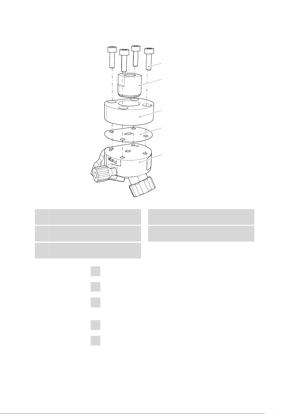
To disassemble the measuring cell, you need a 2.5 mm hexagon key.
Fastening screw (4x)
1
Base part
3
Measuring part
5
With auxiliary electrode.
Figure 3 Disassembling the measuring cell
Pressure screw
2
For fastening the working electrode.
Spacer
4
6.1257.820 or 6.1257.840
Remove the reference electrode.
1
Remove the working electrode.
2
Unscrew the four screws on the base part of the measuring cell with
3
the hexagon key and remove them.
Remove the base part.
4
Remove the spacer.
5
■■■■■■■■
16
IC Equipment Thin-Layer cell
Page 23

■■■■■■■■■■■■■■■■■■■■■■
5 Operation and maintenance
Replace the spacer as follows:
Replacing the spacer
Prerequisites:
■ The measuring cell is disassembled.
■ The new spacer is dry, clean and lint-free.
You will need a 2.5 hexagon key and a pair of tweezers to replace the
spacer.
Wear latex gloves when replacing the spacer.
1
Positioning the spacer
■ Hold the measuring part in your hand as shown in Figure 3, page
16.
■ Use tweezers to place the new spacer on the measuring part.
The straight side of the spacer must lie on the straight edge of the
measuring part and the four small holes in the spacer must be
aligned precisely to the boreholes.
Use your fingertips to hold the spacer in correct position.
2
Attaching the base part
■ Insert the four screws into the boreholes on the base part.
■ Carefully place the base part of the measuring cell:
The straight edge of the base part must lie on the straight edge of
the measuring part and the four screws must fit precisely in the
four boreholes.
Take care to ensure that the boreholes on the base part, the spacer
and the measuring part are aligned precisely with one another.
3
Tightening the screws
Tighten the four screws evenly in cross-over sequence with the hexagon key.
5.2.4 Cleaning the measuring cell
The auxiliary electrode can be readily cleaned when the working electrode
has been removed from the cell.
Cleaning the auxiliary electrode
Prerequisites:
■ The electrode cables are unplugged.
■ The reference electrode has been removed from the measuring cell.
IC Equipment Thin-Layer cell
■■■■■■■■
17
Page 24
5.2 Maintenance
■■■■■■■■■■■■■■■■■■■■■■
■ The working electrode has been removed from the measuring cell.
1
Note
When cleaning the auxiliary electrode, the edges of the spacer
may get damaged.
The spacer must then be replaced.
■ Moisten a cotton swab with 2 mol/L of nitric acid.
■ Use this to carefully wipe the auxiliary electrode.
The edges of the spacer may be damaged when wiping the auxiliary electrode.
If the auxiliary electrode is tenaciously stained, we recommend
that the spacer be removed prior to cleaning the auxiliary electrode (see Chapter 5.2.3, page 15).
Rinse off the measuring cell (except for the working electrode and
2
the reference electrode) under running water and dry with a lint-free
cloth.
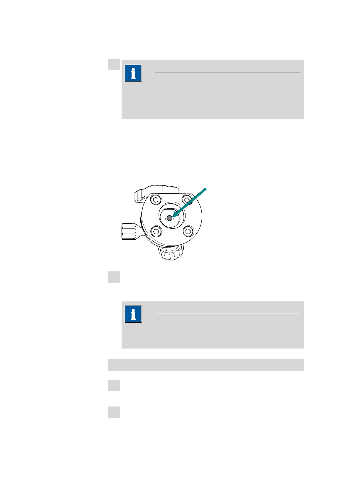
Note
When you rinse off the measuring part, take care to ensure that
the chip in the cell holder does not get wet.
Cleaning the working electrode
Clean the working electrode in accordance with the directions con-
1
tained in the leaflet for the working electrode or polish it if necessary.
Reinsert the working electrode (see Chapter 3.1, page 4).
2
■■■■■■■■
18
IC Equipment Thin-Layer cell
Page 25

■■■■■■■■■■■■■■■■■■■■■■
5 Operation and maintenance
Inserting the reference electrode
Reinsert the reference electrode (see Chapter 3.2, page 5).
1
IC Equipment Thin-Layer cell
■■■■■■■■
19
Page 26

■■■■■■■■■■■■■■■■■■■■■■
6 Technical specifications
Structure Flow cell with working, reference and auxiliary electrode.
Material Cell body made of PEEK.
Cell volume Is dependent on the thickness of the spacer:
50 µm Spacer < 0.35 µL
25 µm Spacer < 0.18 µL
Maximum operating pressure
Cell recognition Intelligent cell with automatic identification and monitoring.
Auxiliary electrode
Type installed
Material Stainless steel
Reference electrode
Type replaceable
Material ■ Palladium solid phase electrode
0.8 MPa (200 psi)
■ Ag/AgCl gel electrode
■■■■■■■■
20
IC Equipment Thin-Layer cell
Page 27

■■■■■■■■■■■■■■■■■■■■■■
7 Accessories
7 Accessories
7.1 IC equipment Thin-Layer cell: without electrodes
Qty. Order no. Description
6.1257.100 Thin-Layer cell
1 6.1257.820 Spacer 50 µm to Thin-Layer cell
Spacer 50 µm for the amperometric Thin-Layer cell, 3 pieces.
1 6.1257.840 Spacer 25 µm to Thin-Layer cell
Spacer 25 µm for the amperometric Thin-Layer cell, 3 pieces.
1 6.1831.010 PEEK capillary 0.25 mm i.d. / 3 m
For all IC components.
Material: PEEK
Outer diameter (mm): 1/16
Inner diameter (mm): 0.25
Length (m): 3
IC Equipment Thin-Layer cell
■■■■■■■■
21
Page 28

7.1 IC equipment Thin-Layer cell: without electrodes
Qty. Order no. Description
1 6.2621.140 Hexagon key 2.5 mm
1 6.2744.014 Pressure screw 2x
With UNF 10/32 connector. For the connection of PEEK capillaries.
Material: PEEK
Length (mm): 26
■■■■■■■■■■■■■■■■■■■■■■
1 6.2802.000 Polishing set for solid-state electrodes
Polishing set wit 1 polishing cloth and about 2 g aluminum oxide
powder (grain size 0.3 µm).
■■■■■■■■
22
IC Equipment Thin-Layer cell
Page 29

■■■■■■■■■■■■■■■■■■■■■■
Index
Index
A
Accessories ............................... 21
Auxiliary electrode
Cleaning ............................. 17
E
Electrode cable
Connecting ........................ 10
I
Installation
Insert Ag/AgCl reference elec-
trode .................................... 6
Insert reference electrode ..... 5
Insert working electrode ....... 4
Measuring cell ...................... 4
M
Measuring cell
Cleaning ............................. 17
Connect capillaries ................ 8
Removing ........................... 13
Taking out .......................... 13
R
Reference electrode
Changing ........................... 14
Exchanging ......................... 14
Installation ........................... 5
Replacing ........................... 14
S
Spacer
Changing ........................... 15
Exchanging ......................... 15
Replacing ........................... 15
T
Technical specifications ............ 20
Thin-Layer cell
Connectors ........................... 3
Construction ......................... 3
Parts ..................................... 3
W
Working electrode .................... 17
Changing ........................... 13
Exchanging ......................... 13
Inserting ............................... 4
Replacing ........................... 13
IC Equipment Thin-Layer cell
■■■■■■■■
23
 Loading...