

Page 1
Power Box
Manual
8.110.8022EN
Page 2

Page 3

Metrohm AG
CH-9100 Herisau
Switzerland
Phone +41 71 353 85 85
Fax +41 71 353 89 01
info@metrohm.com
www.metrohm.com
Power Box
8.110.8022EN
Manual
05.2012 ebe
Page 4

Teachware
Metrohm AG
CH-9100 Herisau
teachware@metrohm.com
This documentation is protected by copyright. All rights reserved.
Although all the information given in this documentation has been
checked with great care, errors cannot be entirely excluded. Should you
notice any mistakes please send us your comments using the address
given above.
Documentation in additional languages can be found on
http://documents.metrohm.com.
Page 5

■■■■■■■■■■■■■■■■■■■■■■
Table of contents
1 Introduction 1
1.1 Description ............................................................................ 1
1.2 Intended use ......................................................................... 1
1.3 About the documentation ................................................... 1
1.3.1 Symbols and conventions ........................................................ 1
1.4 Safety instructions ................................................................ 2
1.4.1 General notes on safety ........................................................... 2
1.4.2 Electrical safety ........................................................................ 2
1.4.3 Recycling and disposal ............................................................. 3
2 Overview 4
3 Installation 5
3.1 Installation location .............................................................. 5
Table of contents
3.2 Connecting the 899 Coulometer to the Power Box .......... 5
3.3 Connecting the power supply unit to the Power Box ....... 6
4 Operation and maintenance 8
4.1 Start-up of the Power Box ................................................... 8
4.1.1 Charging the Power Box .......................................................... 8
4.1.2 Displaying the charge .............................................................. 9
4.2 Operating modes .................................................................. 9
4.3 Using the 899 Coulometer on an unstable power sup-
ply ........................................................................................ 11
4.4 Using the 899 Coulometer not connected to the power
grid ....................................................................................... 12
4.5 Storing the Power Box ....................................................... 12
4.6 Replacing the batteries ...................................................... 13
5 Technical specifications 14
5.1 Power supply ...................................................................... 14
5.2 Safety specifications ........................................................... 14
Power Box
5.3 Electromagnetic compatibility (EMC) ................................ 14
5.4 Ambient temperature ......................................................... 15
5.5 Capacity ............................................................................... 15
5.6 Placement ............................................................................ 15
5.7 Battery ................................................................................. 16
■■■■■■■■
III
Page 6

Table of contents
■■■■■■■■■■■■■■■■■■■■■■
5.8 Dimensions .......................................................................... 16
6 Warranty (Guarantee) 17
Index 19
■■■■■■■■
IV
Power Box
Page 7
■■■■■■■■■■■■■■■■■■■■■■
1 Introduction
1.1 Description
The Power Box is used to provide the 899 Coulometer with an uninterruptible power supply in environments with an unstable or non-existent
mains supply. For instance, you can connect the Power Box to the mains
supply and the 899 Coulometer to the Power Box. If the mains supply fails
while operating the 899 Coulometer, the Power Box automatically starts
supplying power. If you are working completely without a mains supply,
you can operate the 899 Coulometer for at least twelve hours using a
fully-charged Power Box.
1.2 Intended use
The Power Box is intended solely for supplying the 899 Coulometer with
power. No other instruments may be connected to the Power Box.
1 Introduction
1.3 About the documentation
Caution
Please read through this documentation carefully before putting the
instrument into operation. The documentation contains information
and warnings which the user must follow in order to ensure safe operation of the instrument.
1.3.1 Symbols and conventions
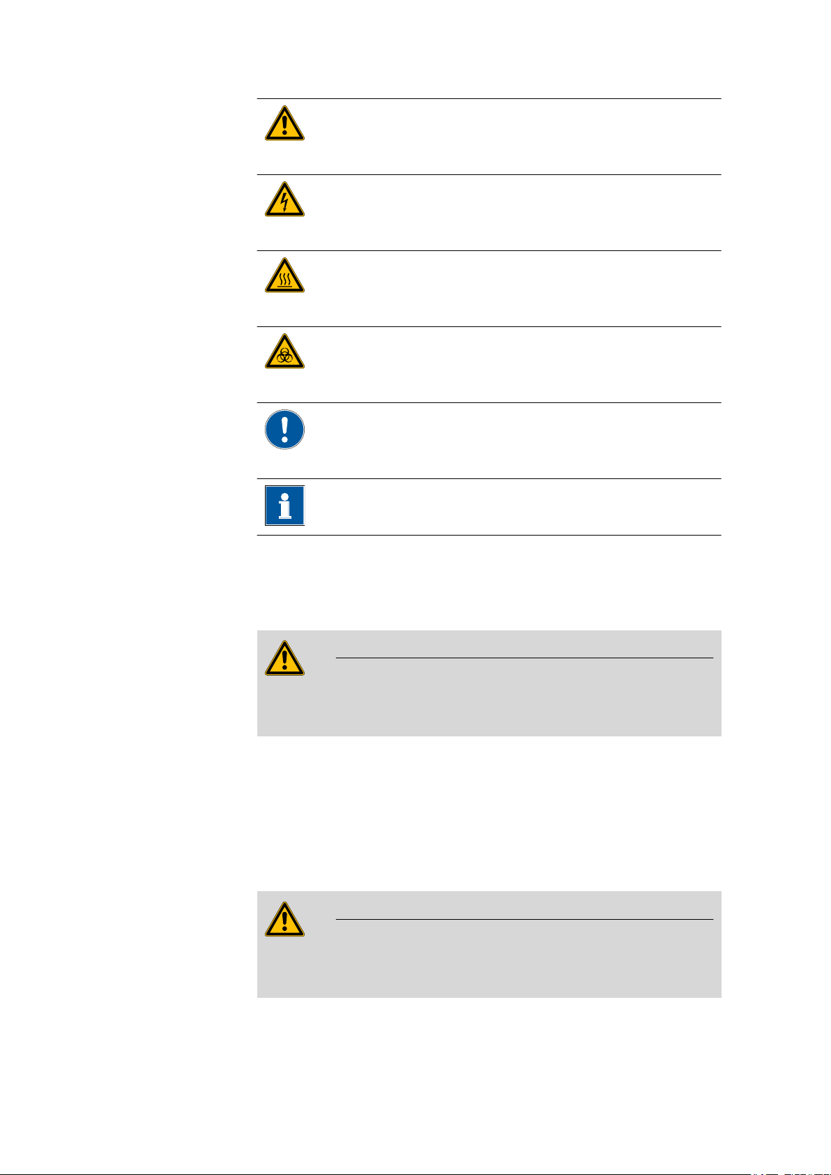
The following symbols and formatting may appear in this documentation:
Cross-reference to figure legend
The first number refers to the figure number, the second to the instrument part in the figure.
Instruction step
Carry out these steps in the sequence shown.
Method Dialog text, parameter in the software
Power Box
File ▶ New Menu or menu item
[Next] Button or key
■■■■■■■■
1
Page 8
1.4 Safety instructions
■■■■■■■■■■■■■■■■■■■■■■
Warning
This symbol draws attention to a possible life hazard
or risk of injury.
Warning
This symbol draws attention to a possible hazard due
to electrical current.
Warning
This symbol draws attention to a possible hazard due
to heat or hot instrument parts.
Warning
This symbol draws attention to a possible biological
hazard.
Caution
This symbol draws attention to a possible damage of
instruments or instrument parts.
1.4 Safety instructions
1.4.1 General notes on safety
Warning
This instrument may only be operated in accordance with the specifications in this documentation.
This instrument has left the factory in a flawless state in terms of technical
safety. To maintain this state and ensure non-hazardous operation of the
instrument, the following instructions must be observed carefully.
1.4.2 Electrical safety
The electrical safety when working with the instrument is ensured as part
of the international standard IEC 61010.
Note
This symbol marks additional information and tips.
■■■■■■■■
2
Warning
Only personnel qualified by Metrohm are authorized to carry out service
work on electronic components.
Power Box
Page 9
■■■■■■■■■■■■■■■■■■■■■■
1 Introduction
Warning
Never open the housing of the instrument. The instrument could be
damaged by this. There is also a risk of serious injury if live components
are touched.
There are no parts inside the housing which can be serviced or replaced
by the user.
Mains voltage
Warning
An incorrect mains voltage can damage the instrument.
Only operate this instrument with a mains voltage specified for it (see
rear panel of the instrument).
1.4.3 Recycling and disposal
This product is covered by European Directive 2002/96/EC, WEEE – Waste
from Electrical and Electronic Equipment.
The correct disposal of your old equipment will help to prevent negative
effects on the environment and public health.
More details about the disposal of your old equipment can be obtained
from your local authorities, from waste disposal companies or from your
local dealer.
Power Box
■■■■■■■■
3
Page 10

2 Overview
1
1 2
3
4
Figure 1 Front Power Box
LED "On"
1
Lights up if the Power Box is being charged
or is partially charged. Lights up more
brightly if the Power Box is fully charged.
■■■■■■■■■■■■■■■■■■■■■■
1
3
■■■■■■■■
4
Figure 2 Rear Power Box
Mains connection socket (In)
For connecting the external power supply
unit (6.2164.010).
Connection cable (Out)
For connecting the Power Box to the 899
Coulometer.
Type plate
2
Contains the serial number.
Mains switch
4
For switching the Power Box on and off.
Power Box
Page 11

■■■■■■■■■■■■■■■■■■■■■■
3 Installation
3.1 Installation location
The Power Box has been developed for operating the 899 Coulometer
with an uninterruptible power supply. It can be used indoors or outdoors.
The Power Box must not be used in environments with explosion or fire
hazards.
Place the instrument in a location which is suitable for operation, free of
vibrations, protected from corrosive atmosphere, and contamination by
chemicals.
Ensure that there is a safety distance of at least 10 cm between the Power
Box's rear panel and parts or devices that can generate sparks. This way,
hydrogen that can be generated in the event of any malfunction in the
power box can safely escape out through the ventilation holes.
3 Installation
The Power Box should be protected against excessive temperature fluctuations and direct sunlight.
3.2 Connecting the 899 Coulometer to the Power Box
Proceed as follows:
Place the 899 Coulometer on the Power Box.
1
Plug in the connection cable (2-3) for the Power Box at the 899 Cou-
2
lometer's mains connection socket (Power).
Note
The connection cable's plug is protected against accidental disconnection of the cable by means of a pull-out protection feature. If
you wish to pull out the plug, you will first need to pull back the
outer plug sleeve.
Power Box
■■■■■■■■
5
Page 12

3.3 Connecting the power supply unit to the Power Box
Figure 3 Connecting the 899 Coulometer to the Power Box
■■■■■■■■■■■■■■■■■■■■■■
3.3 Connecting the power supply unit to the Power Box
The Power Box can be charged while connected to the mains supply by
using the 6.2164.010 power supply unit that is provided with the 899
Coulometer.
Warning
An incorrect mains voltage can damage the Power Box.
Only operate the Power Box at the mains voltage for which it has been
specified. In addition, only use the power supply unit provided with the
899 Coulometer.
Proceed as follows:
Plug in the plug for the power supply unit at the mains connection
1
socket (2-1) for the Power Box.
■■■■■■■■
6
Power Box
Page 13

■■■■■■■■■■■■■■■■■■■■■■
Note
The plug of the power supply unit is protected against accidental
disconnection of the cable by means of a pull-out protection feature. If you wish to pull out the plug, you will first need to pull
back the outer plug sleeve.
Connect the power supply unit to the mains supply using the mains
2
cable.
3 Installation
Power Box
Figure 4 Connecting the power supply unit to the Power Box
Caution
Make sure that the connection cable (2-3) is not plugged in at the
mains connection socket (2-1) accidentally. Otherwise the Power Box
will be discharging needlessly.
■■■■■■■■
7
Page 14

4.1 Start-up of the Power Box
4 Operation and maintenance
4.1 Start-up of the Power Box
Ensure that the following conditions are met before you put the Power
Box into operation together with the 899 Coulometer:
■ The rear panel of the Power Box must be at least 10 cm away from
parts or devices that can generate sparks.
■ The Power Box must be fully charged.
4.1.1 Charging the Power Box
When the Power Box is fully charged, the 899 Coulometer can be operated without a mains supply for at least 12 h. Once the charge drops
below a critical limit, you are prompted via a message on the coulometer
to charge the Power Box.
■■■■■■■■■■■■■■■■■■■■■■
Fully charging the Power Box takes at least 14 h. If there is too little time
for charging after approximately 8 h of operation using the 899 Coulometer, the Power Box can be charged once for 1 h. Afterwards the charge
will suffice for approximately another 8 h of operation. After that, however, the Power Box must be charged for at least 14 h.
To charge the Power Box, proceed as follows:
Plug in the plug for the power supply unit at the mains connection
1
socket (2-1) for the Power Box.
Connect the power supply unit to the mains supply using the mains
2
cable.
Switch on the Power Box.
3
Leave the Power Box connected to the mains supply for at least 14 h.
4
The Power Box cannot be overcharged, even if it is left connected to
the mains supply for more than 14 h.
■■■■■■■■
8
Note
Switch the Power Box off if you are not using it together with the
899 Coulometer immediately after charging. This way you can
avoid an unnecessarily high self-discharge.
Power Box
Page 15

■■■■■■■■■■■■■■■■■■■■■■
4.1.2 Displaying the charge
The state of charge is displayed on the Power Box itself and on the 899
Coulometer's display.
"On" LED on the Power Box
If the Power Box is connected to the mains supply and is switched on, the
LED indicates that the Power Box is in charging mode by lighting up. If the
Power Box is fully charged, the LED's light intensity increases.
If a fully charged Power Box is switched on, it takes approximately 10 s
until the LED displays the full charge by switching to a higher light intensity.
Battery symbol on the 899 Coulometer's display
You can track the Power Box's state of charge using the four-level battery
symbol on the 899 Coulometer's display. This symbol is displayed in the
main dialog and during live display of the conditioning:
4 Operation and maintenance
When the Power Box is in charging mode, the battery symbol fills from
right to left. If the 899 Coulometer is being operated using the Power Box,
the battery symbol empties in the opposite direction.
4.2 Operating modes
The Power Box can be operated with the 899 Coulometer in different
modes. Below you can find all of the operating modes the Power Box can
be operated in.
Power failure mode
■ The power supply unit is connected to the Power Box and to the mains
supply.
■ The Power Box is switched on.
■ The 899 Coulometer is connected to the Power Box.
■ The 899 Coulometer is switched on.
If the mains supply fails, the Power Box takes over continuing operation of
the 899 Coulometer (see Chapter 4.3, page 11).
Charging mode
■ The power supply unit is connected to the Power Box and to the mains
supply.
■ The Power Box is switched on.
■ The 899 Coulometer is connected to the Power Box.
Power Box
■■■■■■■■
9
Page 16

4.2 Operating modes
■■■■■■■■■■■■■■■■■■■■■■
The Power Box is charged no matter whether the 899 Coulometer is
switched on or switched off.
899 Coulometer with the Power Box without power failure
mode
■ The power supply unit is connected to the Power Box and to the mains
supply.
■ The Power Box is switched off.
■ The 899 Coulometer is connected to the Power Box.
■ The 899 Coulometer is switched on.
The 899 Coulometer can be operated normally as long as the mains supply is stable. The Power Box does not take over supplying power if the
mains supply fails. The 899 Coulometer is shut down in a controlled way.
899 Coulometer with the Power Box without power supply
unit
■ The Power Box is fully charged and switched on.
■ The Power Box is not connected to the power supply unit and the
mains supply.
■ The 899 Coulometer is connected to the Power Box.
■ The 899 Coulometer is switched on.
The 899 Coulometer can be operated for at least 12 h (see Chapter 4.4,
page 12).
Stand-alone operation
■ The power supply unit is connected to the Power Box and to the mains
supply.
■ The Power Box is switched on.
The Power Box is charged. Once it is fully charged, the LED switches to a
higher light intensity (1-1).
The intelligence of the Power Box prevents overcharging, even if the
Power Box is connected to the mains supply for more than 14 h.
■■■■■■■■
10
Power Box
Page 17

■■■■■■■■■■■■■■■■■■■■■■
4 Operation and maintenance
4.3 Using the 899 Coulometer on an unstable power supply
If you are working in an environment where only an unstable power supply is available, you can operate the 899 Coulometer as follows:
Connect the 899 Coulometer to the Power Box.
1
Plug in the 6.2164.010 power supply unit at the power socket (2-1)
2
for the Power Box and connect it to the power supply.
Switch on the Power Box.
3
Switch on the 899 Coulometer.
4
If the power supply fails, the Power Box takes over providing the 899
Coulometer with power. Once the charge drops below a critical limit,
you are prompted via a message on the Coulometer to charge the
Power Box.
Note
If you continue to operate the coulometer after this message is
displayed without charging the Power Box, it will be switched off
automatically after a certain time. This automatic process prevents
a deep discharge of the Power Box during operation with a 899
Coulometer. Depending on the availability of the power supply,
the coulometer is also shut down in a controlled way.
The Power Box ends up in charging mode no matter whether the coulometer is switched on or switched off. You can tell by the LED on the front of
the instrument lighting up.
Power Box
■■■■■■■■
11
Page 18

4.4 Using the 899 Coulometer not connected to the power grid
■■■■■■■■■■■■■■■■■■■■■■
4.4 Using the 899 Coulometer not connected to the
power grid
If you are working in an environment without an available power supply,
you can operate the 899 Coulometer as follows:
Connect the 899 Coulometer to the fully-charged Power Box.
1
Switch on the Power Box.
2
Switch on the 899 Coulometer.
3
After 12 h of operation at the earliest, you will be prompted via a
message on the coulometer to charge the Power Box.
Note
If you continue to operate the coulometer after this message is
displayed without charging the Power Box, it will be switched off
automatically after a certain time. This automatic process prevents
a deep discharge of the Power Box during operation with a 899
Coulometer. The 899 Coulometer is shut down in a controlled
way.
4.5 Storing the Power Box
Caution
If the Power Box is not being used for an extended period, the batteries
may be damaged by a deep discharge. This also occurs if the Power Box
is switched off. The discharge can amount to 3% per month. Repeated
deep discharges can shorten the life of the batteries and lower their
capacity.
Avoid deep discharges and keep the following in mind:
■■■■■■■■
12
■ Ensure that the Power Box is fully charged before you put it in storage.
■ Switch off the Power Box before you put it in storage.
■ If you keep the Power Box in storage or do not use it for 12 months, it
must be charged after this period for at least 14 hours using the
6.2164.010 power supply unit.
Power Box
Page 19
■■■■■■■■■■■■■■■■■■■■■■
4.6 Replacing the batteries
Warning
Never open the housing of the instrument. The instrument could be
damaged by this. There is also a risk of serious injury if live components
are touched.
There are no parts inside the housing which can be serviced or replaced
by the user.
Contact your local Metrohm Service to replace dead or defective batteries.
Note
Warranty
4 Operation and maintenance
The batteries are considered consumables. A 6-month warranty is granted starting from the day of delivery.
Power Box
■■■■■■■■
13
Page 20

5.1 Power supply
5 Technical specifications
5.1 Power supply
■■■■■■■■■■■■■■■■■■■■■■
External power
24 V, 65 W
supply unit
(6.2164.010)
Input voltage 24 V DC (± 3%)
Input current max. 600 mA
Output voltage
19 - 28 V
range
Output current max. 2 A
Fuse 2.5 A, slow-acting
5.2 Safety specifications
This instrument fulfills the following electrical safety requirements:
CE designation in accordance with the EU directives:
■ 2006/95/EC (Low Voltage Directive, LVD)
■ 2004/108/EC (EMC Directive, EMC)
Design and testing According to EN/IEC/UL 61010-1, CSA-C22.2 No. 61010-1, protection
class III, EN/IEC 60529, degree of protection IP31.
Safety instructions This document contains safety instructions which have to be followed
by the user in order to ensure safe operation of the instrument.
5.3 Electromagnetic compatibility (EMC)
Emission
Standards fulfilled
Immunity
Standards fulfilled
■■■■■■■■
14
■ EN/IEC 61326-1
■ EN/IEC 61000-6-3
■ EN 55011 / CISPR 11
■ EN/IEC 61326-1
■ EN/IEC 61000-6-2
■ EN/IEC 61000-4-2
■ EN/IEC 61000-4-3
■ EN/IEC 61000-4-4
■ EN/IEC 61000-4-5
Power Box
Page 21

■■■■■■■■■■■■■■■■■■■■■■
■ EN/IEC 61000-4-6
■ EN/IEC 61000-4-11
■ EN/IEC 61000-4-14
■ EN/IEC 61000-4-28
5.4 Ambient temperature
5 Technical specifications
Nominal function
range
0 - +40 °C
(at a maximum of 85% humidity)
Storage –20 - +60 °C
Transport –20 - +60 °C
5.5 Capacity
Maximum
capacity
Usable capacity 90%
Work with a 899
Coulometer:
Remarks After a typical titration operation lasting 8 h, the Power Box can be
4 Ah
12 h of continuous operation during standard titration (120 s of titration, 180 s of conditioning, 1200 µg of water).
charged for approximately 1 h. This can allow for another 8 h of operation. Afterwards, the Power Box must be charged for 14 h (full
charge).
5.6 Placement
Safety distance
Power Box
Minimum safety distance between the rear panel of the Power Box and
parts and devices that can generate sparks:
■ 10 cm (in accordance with EN 50272-2)
An 899 Coulometer can be placed on top of the Power Box.
■■■■■■■■
15
Page 22

5.7 Battery
■■■■■■■■■■■■■■■■■■■■■■
5.7 Battery
Type NP4-12 YUASA (2 pieces)
Approvals UN2800 / EN/IEC 61056 / VDE/UL MH12970 / MH28018
Air transport UN2800 / Class 8 / Packaging group 3
Ocean transport UN2800 / Class 8 / Packaging group 3
Surface transport UN2800 / Class 8 / Packaging group 3
Nominal voltage 12 V DC each (= 24 V DC, series circuit)
Capacity max. 4 Ah
Charging time ≤ 14 h
Capacity loss ≤ 3% per month
Dimensions L × W
× H
Weight 1,750 g
90 × 70 × 106 mm
5.8 Dimensions
Width
Height 86 mm
Depth 330 mm
Material
Housing Steel sheet
Weight 5,500 g
141.5 mm
■■■■■■■■
16
Power Box
Page 23

■■■■■■■■■■■■■■■■■■■■■■
6 Warranty (Guarantee)
Metrohm guarantees that the deliveries and services it provides are free of
errors in materials, design or manufacturing.
The general warranty period is 36 months (exclusions below) from the
date of delivery or 18 months in the event of continuous operation. The
warranty remains valid on the condition that the servicing is provided by a
Service Organization authorized by Metrohm at defined intervals and with
a defined scope.
The warranty period for anion suppressors is 120 months from the date of
delivery or 60 months in the event of continuous operation.
The warranty period for IC separation columns is 90 days after start-up.
For third-party components that are recognizable as such, the manufacturer's warranty regulations apply.
Consumables and materials with limited storage life and glass breakage in
the case of electrodes or other glass parts are excluded from the warranty.
6 Warranty (Guarantee)
Warranty claims cannot be asserted if the customer has failed to meet his
payment obligations according to schedule.
During the warranty period, Metrohm undertakes either to replace free of
charge or to credit the purchaser for any assemblies or components that
can be shown to be faulty. Any transport or customs fees that may apply
are the ordering party’s responsibility.
The precondition for this is that the ordering party must use the Return
Material Authorization (RMA) to report the faulty part, along with specification of the article number, the article designation, an adequate error
description, the delivery date and (if applicable) the serial number or the
chip data, respectively. In addition, the ordering party undertakes to store
the faulty part for at least 24 months in accordance with current storage
directives (in compliance with ESD guidelines) and to hold it in readiness
for onsite inspection or for return shipment to Metrohm. Metrohm
reserves the right to invoice the ordering party for these articles, including
retroactively, in the event of noncompliance with these pre-conditions.
The original warranty periods for the original part apply to parts that are
replaced or repaired under the above-referenced warranties (no extension
of the warranty period).
Power Box
Deficiencies arising from circumstances that are not the responsibility of
Metrohm, such as improper storage or improper use, etc., are expressly
excluded from the warranty.
■■■■■■■■
17
Page 24

■■■■■■■■■■■■■■■■■■■■■■
Metrohm also offers a 120-month spare parts availability guarantee and a
60-month PC software support warranty, calculated from the date on
which the product is withdrawn from the market. The content of this warranty is the ability of the customer to obtain functioning spare parts or
appropriate software support at market prices during the time of the warranty period.
If Metrohm AG is unable to meet this obligation due to circumstances
beyond the control of Metrohm AG, then the ordering party shall be
offered alternative solutions at preferential conditions.
■■■■■■■■
18
Power Box
Page 25

■■■■■■■■■■■■■■■■■■■■■■
Index
Index
Numbers/Symbols
899 Coulometer
Connect ............................... 5
C
Charging mode .......................... 9
Charging time ............................ 8
G
Guarantee ................................ 17
M
Mains independence ................ 10
Mains voltage ............................. 3
O
Operating mode ......................... 9
Operating time
Full charge ............................ 8
P
Power Box
Charge ................................. 8
Front .................................... 4
Operating mode ................... 9
Rear ..................................... 4
Power failure .............................. 9
Power grid independence ......... 12
Power supply
Unstable ............................. 11
Power supply unit
Connect ............................... 6
S
Safety instructions ...................... 2
Service ....................................... 2
Setup
Conditions ............................ 5
Safety distance ................. 5, 8
Stand-alone operation .............. 10
Start-up
Conditions ............................ 8
State of charge
Battery symbol ...................... 9
Coulometer .......................... 9
Power Box ............................ 9
Storage
Conditions .......................... 12
W
Warning
Charge Power Box .... 8, 11, 12
Warranty .................................. 17
Power Box
■■■■■■■■
19
 Loading...