

Page 1

OMNIS Sample Robot Pick&Place
2.101X.1010
Product manual
8.1012.8001EN / 2018-08-17
Page 2

Page 3

Metrohm AG
Ionenstrasse
CH-9100 Herisau
Switzerland
Phone +41 71 353 85 85
Fax +41 71 353 89 01
info@metrohm.com
www.metrohm.com
OMNIS Sample Robot Pick&Place
2.101X.1010
8.1012.8001EN /
2018-08-17
Product manual
Page 4

Technical Communication
Metrohm AG
CH-9100 Herisau
techcom@metrohm.com
This documentation is protected by copyright. All rights reserved.
This documentation has been prepared with great care. However, errors
can never be entirely ruled out. Please send comments regarding possible
errors to the address above.
Page 5

■■■■■■■■■■■■■■■■■■■■■■
Table of contents
1 Overview 1
1.1 OMNIS Sample Robot Pick&Place – Product descrip-
1.2 OMNIS Sample Robot Pick&Place – Product versions ....... 1
1.3 Main module Pick&Place – Product versions ..................... 2
1.4 Pick&Place module – Product versions ............................... 3
1.5 Peristaltic pump module – Product versions ...................... 3
1.6 OMNIS Sample Robot Pick&Place – License versions ........ 4
1.7 About the documentation ................................................... 5
1.8 Additional information ......................................................... 5
1.8.1 Accessories .............................................................................. 5
Table of contents
tion ......................................................................................... 1
2 Safety 7
2.1 Product safety ....................................................................... 7
2.2 Hazard levels ......................................................................... 7
2.3 Warning symbols .................................................................. 8
2.4 Intended use ......................................................................... 9
2.5 Residual risks ........................................................................ 9
2.5.1 General dangers at the workplace ........................................... 9
2.5.2 Danger from electrical potential ............................................. 10
2.5.3 Danger from machine movements ......................................... 11
2.5.4 Danger from biological substances ........................................ 11
2.5.5 Danger from highly flammable substances ............................. 12
2.5.6 Danger from careless transport .............................................. 12
2.5.7 Danger from leakage ............................................................. 12
2.5.8 Danger from high temperatures ............................................. 13
2.6 Responsibility of the operator ........................................... 13
2.7 Personnel requirement ....................................................... 13
3 Functional description 14
3.1 System overview ................................................................. 14
3.1.1 System – Signals .................................................................... 14
3.1.2 System – Interfaces ................................................................ 15
OMNIS Sample Robot Pick&Place
3.2 Overview – OMNIS Sample Robot Pick&Place S .............. 16
3.3 Overview – OMNIS Sample Robot Pick&Place M ............ 17
3.4 Overview – OMNIS Sample Robot Pick&Place L .............. 18
3.4.1 Main module Pick&Place – Overview ...................................... 19
■■■■■■■■
III
Page 6

Table of contents
■■■■■■■■■■■■■■■■■■■■■■
3.4.2 Pick&Place module – Overview .............................................. 21
3.4.3 Peristaltic pump module – Overview ...................................... 24
3.4.4 Rack base – Overview ............................................................ 28
3.5 Sample Robot Pick&Place – Functional description ........ 29
3.5.1 Main module Pick&Place – Functional description .................. 30
3.5.2 Pick&Place module – Functional description ........................... 30
3.5.3 OMNIS peristaltic pump module – Functional description ....... 30
3.5.4 Rack base – Functional description ......................................... 31
3.6 OMNIS Sample Robot – Indicators and controls ............. 32
3.7 Main module – Connectors ................................................ 33
4 Transport and storage 34
4.1 Checking the delivery ......................................................... 34
4.2 Storing the packaging ........................................................ 34
4.3 Lifting the sample robot .................................................... 34
5 Installation 35
5.1 Installation by Metrohm .................................................... 35
5.2 Sample robot setting up .................................................... 35
5.3 Replacing the seal of the sample beaker lid .................... 36
5.4 Inserting and equipping the titration head ...................... 38
5.5 Mounting the safety shield ................................................ 44
5.6 Connecting the tubing to the distributor of the
Pick&Place module ............................................................. 46
5.7 Connecting the drainage tubing ....................................... 48
5.8 Connecting the inlet and outlet tubing ............................ 49
5.9 Connecting/Disconnecting the power cord ...................... 50
6 Initial start-up 52
6.1 Initial start-up by Metrohm ............................................... 52
7 Operation and control 53
7.1 Operation ............................................................................ 53
7.2 Switching the OMNIS sample robot on and off ............... 53
7.3 Opening the gripper manually .......................................... 54
■■■■■■■■
IV
7.4 Attaching and removing the sample rack ........................ 55
8 Maintenance 58
8.1 General maintenance ......................................................... 58
8.2 Maintenance agreement .................................................... 59
OMNIS Sample Robot Pick&Place
Page 7

■■■■■■■■■■■■■■■■■■■■■■
9 Malfunctions and troubleshooting 83
10 Disposal 84
11 Technical specifications 85
Table of contents
8.3 Cleaning the product .......................................................... 60
8.3.1 Cleaning the Pick&Place module ............................................ 61
8.4 Checking and replacing product parts .............................. 67
8.4.1 Replacing the finger tip and PTFE sleeve ................................. 68
8.4.2 Replacing the beaker adapter ................................................ 70
8.4.3 Replacing the titration head ................................................... 73
8.4.4 Checking the pump tubing .................................................... 76
8.4.5 Replacing the pump tubing .................................................... 78
9.1 Troubleshooting .................................................................. 83
11.1 Ambient conditions ............................................................ 85
11.2 Main module – Energy supply ........................................... 85
11.3 Pick&Place module – Energy supply ................................. 85
11.4 Peristaltic pump module – Energy supply ........................ 86
11.5 OMNIS sample rack – Energy supply ................................ 86
11.6 OMNIS Sample Robot Pick&Place – Dimensions ............. 86
11.7 Main module Pick&Place – Dimensions ............................ 87
11.8 Pick&Place module – Dimensions ..................................... 88
11.9 Peristaltic pump module – Dimensions ............................ 88
11.10 OMNIS rack base / OMNIS module base – Dimensions .. 89
11.11 OMNIS sample rack – Dimensions .................................... 89
11.12 Main module Pick&Place – Housing ................................. 90
11.13 Pick&Place module – Housing ........................................... 90
11.14 Peristaltic pump module – Housing .................................. 91
11.15 OMNIS Sample Robot Pick&Place – Housing ................... 91
11.16 OMNIS module base – Housing ......................................... 91
11.17 OMNIS sample rack – Housing .......................................... 92
11.18 Main modules – Connectors specifications ...................... 92
11.19 OMNIS Sample Robot module – Connectors specifica-
tions ..................................................................................... 93
OMNIS Sample Robot Pick&Place
11.20 OMNIS rack base – Connectors specifications ................. 93
11.21 OMNIS sample rack – Connectors specifications ............. 93
11.22 OMNIS Sample Robot Pick&Place – Display specifica-
tions ..................................................................................... 93
■■■■■■■■
V
Page 8

Table of contents
■■■■■■■■■■■■■■■■■■■■■■
11.23 Peristaltic pump module – Liquid Handling specifica-
tions ..................................................................................... 93
11.24 Magnetic stirrer – Stirrer specifications ............................ 94
11.25 OMNIS Sample Robot Pick&Place – Sample handling
specifications ...................................................................... 94
11.26 OMNIS sample rack – Sample handling specifications ... 95
■■■■■■■■
VI
OMNIS Sample Robot Pick&Place
Page 9

■■■■■■■■■■■■■■■■■■■■■■
Overview
1 Overview
1.1 OMNIS Sample Robot Pick&Place – Product description
The OMNIS Sample Robot Pick&Place system is suitable for use with titrations involving automatic sample changes.
The modular construction makes it possible to configure the system in
accordance with the area of application.
The OMNIS Software is used to control the system. The system is connected to the Ethernet network for that purpose.
1.2 OMNIS Sample Robot Pick&Place – Product versions
The OMNIS Sample Robot can be configured individually. The OMNIS
Sample Robot Pick&Place is available in the following versions as framework for the configuration:
Table 1
Art. no. Designation Version feature
2.1010.1010 OMNIS Sample Robot S Pick&Place S version
2.1011.1010 OMNIS Sample Robot M Pick&Place M version
2.1012.1010 OMNIS Sample Robot L Pick&Place L version
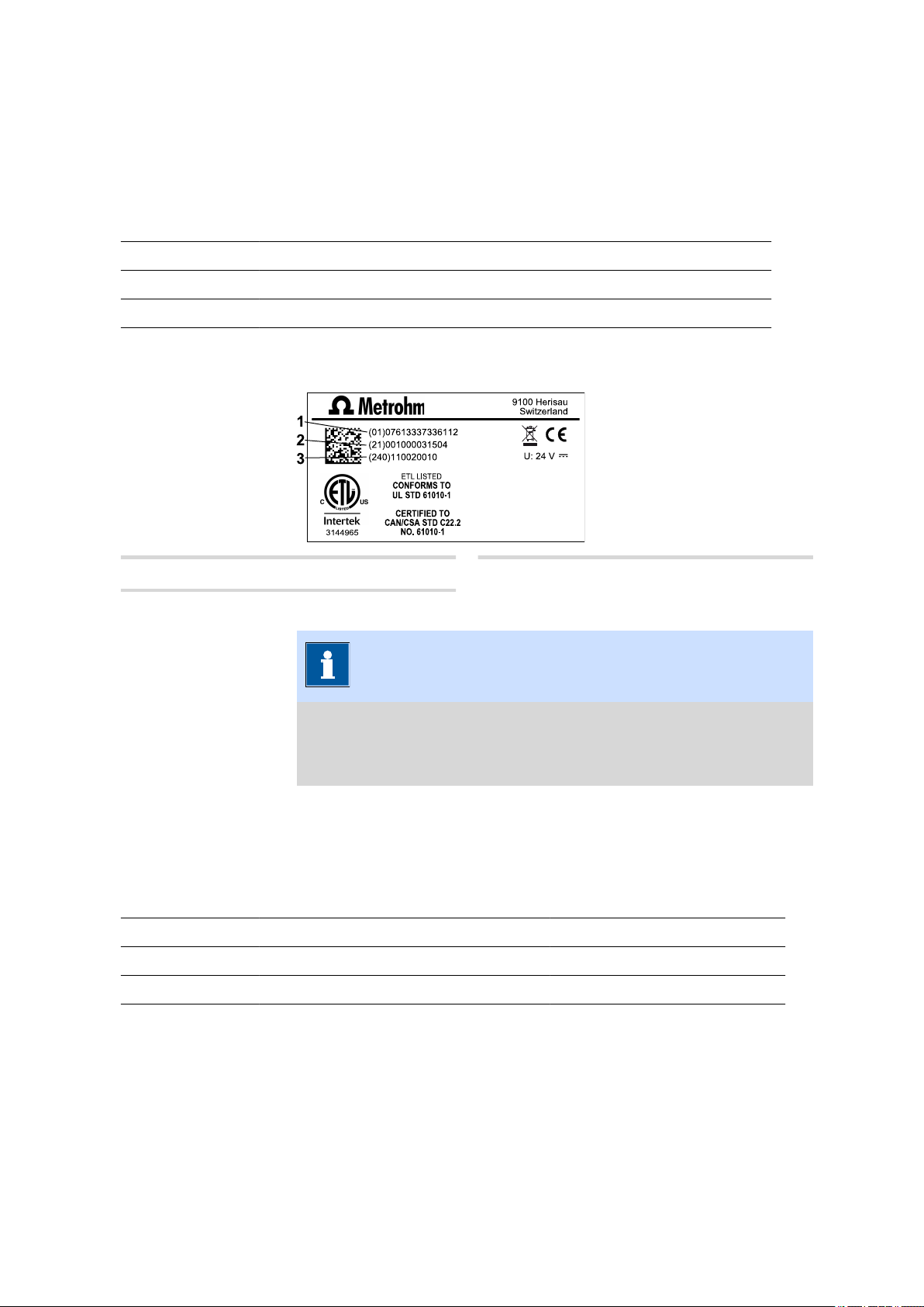
The required numbers for the customer service can be found on the type
plate (see example):
(01) = external article number
1
Product versions
(21) = Serial number
2
(240) = Metrohm article number
3
■■■■■■■■
1
Page 10

Main module Pick&Place – Product versions
■■■■■■■■■■■■■■■■■■■■■■
NOTICE
Information on the accessories for the respective product version can
be obtained either on the Internet at http://www.metrohm.com or
via your regional Metrohm representative.
1.3 Main module Pick&Place – Product versions
The product is available in the following versions:
Table 2
Art. no. Designation Version feature
2.1010.0010 Main module Pick&Place S Main module Pick&Place, S version
2.1011.0010 Main module Pick&Place M Main module Pick&Place, M version
2.1012.0010 Main module Pick&Place L Main module Pick&Place, L version
The required numbers for the customer service can be found on the type
plate (see example):
(01) = External article number
1
(240) = Metrohm article number
3
Product versions
(21) = Serial number
2
■■■■■■■■
2
NOTICE
Information on the accessories for the respective product version can
be obtained either on the Internet at http://www.metrohm.com or
via your regional Metrohm representative.
Page 11
■■■■■■■■■■■■■■■■■■■■■■
1.4 Pick&Place module – Product versions
The product is available in the following versions:
Table 3 Product versions
Art. no. Designation Version feature
2.1014.0010 Pick&Place module Without magnetic stirrer
2.1014.0110 Pick&Place module With integrated magnetic stirrer
The required numbers for the customer service can be found on the type
plate (see example):
Overview
(01) = External article number
1
(240) = Metrohm article number
3
(21) = Serial number
2
NOTICE
Information on the accessories for the respective product version can
be obtained either on the Internet at http://www.metrohm.com or
via your regional Metrohm representative.
1.5 Peristaltic pump module – Product versions
The product is available in the following versions:
Table 4
Art. no. Designation Version feature
2.1016.0010 Peristaltic pump module (2-channel) 2 installed peristaltic pumps
2.1016.0110 Peristaltic pump module (4-channel) 4 installed peristaltic pumps
Product versions
The required numbers for the customer service can be found on the type
plate (see example):
■■■■■■■■
3
Page 12
OMNIS Sample Robot Pick&Place – License versions
■■■■■■■■■■■■■■■■■■■■■■
(01) = External article number
1
(240) = Metrohm article number
3
(21) = Serial number
2
NOTICE
Information on the accessories for the respective product version can
be obtained either on the Internet at http://www.metrohm.com or
via your regional Metrohm representative.
1.6 OMNIS Sample Robot Pick&Place – License versions
The licenses are available in the following versions:
Table 5
Art. no. Designation Version feature
6.06005.010 Function license S Included in the scope of delivery
6.06005.020 Function license M Included in the scope of delivery
License versions
of the main module Pick&Place
of the main module Pick&Place
6.06005.030 Function license L Included in the scope of delivery
of the main module Pick&Place
6.06005.910 Function license update S – M Update
6.06005.920 Function license update S – L Update
6.06005.930 Function license update M – L Update
NOTICE
Further information on the respective license version can be obtained
either on the Internet at http://www.metrohm.com or via your
regional Metrohm representative.
■■■■■■■■
4
Page 13
■■■■■■■■■■■■■■■■■■■■■■
1.7 About the documentation
NOTICE
Please read through this documentation carefully before putting the
product into operation.
The documentation contains important information and warnings
which you must follow in order to ensure safe operation of the product.
Symbols and conventions
The following icons and formatting may appear in this documentation:
Cross-reference to figure legend
The first number refers to the figure number, the second to the product part in the figure.
Overview
Instruction step
Carry out these steps in the sequence shown.
Method Designations for names of parameters, menu items,
tabs and dialog windows in the software.
File ▶ New Menu or menu item
Work area /
Properties
[Next] Button or key
Menu paths in order to arrive at a particular position
in the software.
1.8 Additional information
Additional information concerning the topic can be found:
■ in the Software Help
■ in the Metrohm information portal on the Internet https://
guide.metrohm.com
1.8.1 Accessories
Up-to-date information on the scope of delivery and optional accessories
for your product can be found on the Internet. You can download this
information using the article number as follows:
■■■■■■■■
5
Page 14

Additional information
■■■■■■■■■■■■■■■■■■■■■■
Downloading the accessories list
Enter https://www.metrohm.com/ into your Internet browser.
1
Enter the article number of the product (e.g. 2.1001.0010) into the
2
search field.
The search result is displayed.
Click on the product.
3
Detailed information regarding the product is shown on various tabs.
On the Included parts tab, click Download the PDF.
4
The PDF file with the accessories data is created.
NOTICE
When you receive your new product, we recommend downloading
the accessories list from the Internet, printing it out and keeping it for
reference purposes.
■■■■■■■■
6
Page 15

■■■■■■■■■■■■■■■■■■■■■■
2 Safety
2.1 Product safety
This product exhibited no flaws in terms of technical safety at the time it
left the factory. To preserve this status and ensure non-hazardous operation of the product, the following instructions must be observed carefully.
2.2 Hazard levels
The following warning messages indicate the severity of the danger and
its possible effects.
Safety
DANGER
Immediate danger of life
Irreversible injuries that will result in death.
Warns of dangerous situations or unsafe actions that will most certainly cause severe injuries or death.
Lists measures to avoid hazard.
WARNING
Severe health hazards
Serious injuries that could result in death.
Warns of dangerous situations or unsafe actions that could result in
serious injuries or death.
Lists measures to avoid hazard.
■■■■■■■■
7
Page 16

Warning symbols
CAUTION
Health hazards or severe property damage
Warns of dangerous situations or unsafe actions that could result in
moderate injuries or considerable property damage.
Lists measures to avoid hazard.
2.3 Warning symbols
Make sure that any additional hazard symbols are marked on the product
for your operation of the product.
The following warning symbols in the documentation and at hazard areas
of the product point out hazard potentials:
– Warning of a hazard area
■■■■■■■■■■■■■■■■■■■■■■
NOTICE
Warning symbol on the product
If this warning symbol is on the product, read the respective documentation prior to installation and initial start-up.
– Warning of electric shock from electrical potential
– Warning of danger of fire and explosion from highly flammable
substances and gases
– Warning of danger of poisoning and chemical burns from chemi-
cal hazardous substances
– Warning of danger of infection and poisoning from biological
hazardous substances
■■■■■■■■
8
– Warning of risk of injury from high temperatures
Page 17

■■■■■■■■■■■■■■■■■■■■■■
– Warning of cut injuries from pieces of broken glass and/or sharp
edges
– Warning of risk of injury by laser radiation
– Warning of dangerous optical radiation
2.4 Intended use
Metrohm products are used for the analysis and handling of chemicals.
Usage therefore requires the user to have basic knowledge and experience
in handling chemicals. Knowledge regarding the application of fire prevention measures prescribed for laboratories is also mandatory.
Adherence to this technical documentation and compliance with the
maintenance specifications make up an important part of intended use.
Safety
Any utilization in excess of or deviating from the intended use is regarded
as misuse.
Specifications regarding the operating values and limit values of individual
products are contained in the "Technical specifications" section, if relevant.
Exceeding and/or not observing the mentioned limit values during operation puts people and components at risk. The manufacturer assumes no
liability for damage due to non-observance of these limit values.
The EU declaration of conformity loses its validity if modifications are carried out on the products and/or the components.
2.5 Residual risks
2.5.1 General dangers at the workplace
Generally, the regulations and provisions of the regulatory institutions and
authorities in the field of work apply.
The instructions regarding the following areas have to be followed when
using the products:
■ Work safety
■ Handling mechanical installations
■ Handling electricity
■ Handling hazardous and environmentally damaging substances
■ Handling hazardous and environmentally damaging liquids
■ Disposing hazardous and environmentally damaging substances
If they are not followed, this may result in:
■■■■■■■■
9
Page 18

Residual risks
■■■■■■■■■■■■■■■■■■■■■■
■ Disturbing, injuring and/or killing of people
■ Malfunction and/or damage to instruments and infrastructure
■ Damage and/or contamination of the environment
WARNING
General dangers at workplace
If the safety measures are not followed, working in a laboratory bears
a high risk of injury, which can endanger your life and health.
■ Only professionally trained and qualified specialist personnel may
operate the products.
■ Follow the applicable provisions concerning work safety and all
regulations on wearing protective clothing.
■ Use suitable tools to perform your work.
■ Check the fill level of waste bottles or waste canisters and analysis
vessels, and make sure they do not overflow.
■ Use protective grounding when working with highly flammable
substances and gases.
2.5.2 Danger from electrical potential
WARNING
Electric shock from electrical potential
Risk of injury by touching live components or through moisture on
live parts.
■ Never open the housing of the instrument.
■ Protect live parts (e.g. power supply unit, power cord, connection
sockets) against moisture.
■ If you suspect that moisture has gotten into the instrument, dis-
connect the instrument from the energy supply. Then notify Metrohm Service.
■ Only personnel who have been issued Metrohm qualification may
perform service and repair work on electrical and electronic components.
10
■■■■■■■■
Page 19

■■■■■■■■■■■■■■■■■■■■■■
2.5.3 Danger from machine movements
WARNING
Risk of squashing and pinching from machine movements
Injuries from movable instrument parts.
■ Do not reach into the working area of the instruments during the
work process.
■ Install and use the protective devices enclosed with the product
during the work process.
■ Do not bypass the installed protective devices.
2.5.4 Danger from biological substances
If the product is used for biological hazardous substances, it must be
marked in accordance with regulations.
In case of a return shipment to Metrohm or a Metrohm Service partner,
the product or product component has to be decontaminated and the
hazard symbol for biological hazardous substances must be removed. A
declaration of decontamination must be enclosed.
Safety
WARNING
Danger of infection and poisoning from biological hazardous
substances
Poisoning from toxins and/or infections from samples contaminated
with microorganisms.
■ Clean and disinfect contaminated surfaces.
■ Wear protective equipment.
■ Use exhaust equipment when working with vaporizing hazardous
substances.
■ Dispose of biologically contaminated substances properly.
■■■■■■■■
11
Page 20
Residual risks
2.5.5 Danger from highly flammable substances
WARNING
Danger of fire and explosion from highly flammable substances
and gases
Burns from fire and/or injuries from explosions.
■ Avoid ignition sources.
■ Use protective grounding.
■ Use exhaust equipment.
2.5.6 Danger from careless transport
WARNING
■■■■■■■■■■■■■■■■■■■■■■
Risk of injury from careless transport
Injuries from spilled chemical and/or biological substances, falling
parts and pieces of broken glass.
■ Remove loose parts (e.g. sample racks, sample beaker, bottles)
before transport.
■ Remove liquids.
■ Lift and transport the instrument with both hands on the base
plate.
■ Lift and transport heavy instruments only according to instruc-
tions.
2.5.7 Danger from leakage
WARNING
Risk of injury by leakage
A risk of injury exists in connection with escaping liquids of leaking
parts and/or connection elements.
12
■ Replace leaking parts and connection elements without delay.
■ Tighten loose connecting elements.
■ Use environmentally-friendly methods to dispose of escaping liq-
uids.
■■■■■■■■
Page 21

■■■■■■■■■■■■■■■■■■■■■■
2.5.8 Danger from high temperatures
WARNING
Risk of injury from high temperatures
Burns from hot surfaces and/or hot liquids.
■ Install and use the protective devices enclosed with the product.
■ Wear protective gloves while working in hot areas.
■ Clean up spilled liquids and solids immediately.
2.6 Responsibility of the operator
■ Eliminate defects or damage which impair operating safety without
delay.
■ Eliminate malfunctions which could impair safety without delay.
■ The rules, regulations and instructions listed in the present document
are not the only valid ones. Comply with the applicable statutory rules,
government agency directives and regulations.
■ Unauthorized modification of the products excludes any and all liability
on the part of the manufacturer for any damage resulting from this as
well as for any consequential damage. No modifications, attachments
or conversions which could impair safety may be carried out on the
products without the approval of the manufacturer.
■ Spare parts must meet the technical requirements established by the
manufacturer. Original spare parts always meet these requirements.
■ Personnel must be familiar with this safety-relevant information and it
must be available for consultation at all times.
Safety
2.7 Personnel requirement
Only qualified personnel may operate the present product.
Qualified personnel are people authorized by the safety responsible to
carry out the necessary operations. They are capable of recognizing and
avoiding possible dangers. These people are qualified due to their professional training, experience and/or instruction. They know the relevant
standards, laws, provisions, accident prevention regulations and the company conditions.
■■■■■■■■
13
Page 22
System overview
3 Functional description
3.1 System overview
3.1.1 System – Signals
Visual signals
All products and components of the system that are equipped with multicolor status displays indicate their respective status using colors and flashing patterns.
The meaning of the colors and flashing patterns is explained in the following table.
NOTICE
■■■■■■■■■■■■■■■■■■■■■■
Use of the flashing patterns
Not all products and components use all of the flashing patterns illustrated below.
However, the meaning of the flashing patterns is the same for all
products and components.
Signal Meaning
LED lights up yellow System start or initialization
LED flashes yellow (slowly) Ready for connection setup or
locking
LED flashes yellow (fast) Connection setup started or
locking underway
LED lights up green Ready for operation
LED flashes green (slowly) In operation
LED flashes red (fast) Malfunction or error
14
■■■■■■■■
Page 23

■■■■■■■■■■■■■■■■■■■■■■
3.1.2 System – Interfaces
The system provides the following interfaces:
Functional description
Designation Abbrevia-
Symbol Use
tion
Metrohm Device Link MDL For connecting additional mod-
ules or products to a basic product.
Human Interactive Device HID For connecting an external con-
trol product.
Metrohm Solution Identification MSI For connecting the OMNIS Liq-
uid Adapter.
Local Area Network LAN For connecting the product to a
local network.
USB connector USB For connecting USB devices.
■■■■■■■■
15
Page 24
Overview – OMNIS Sample Robot Pick&Place S
■■■■■■■■■■■■■■■■■■■■■■
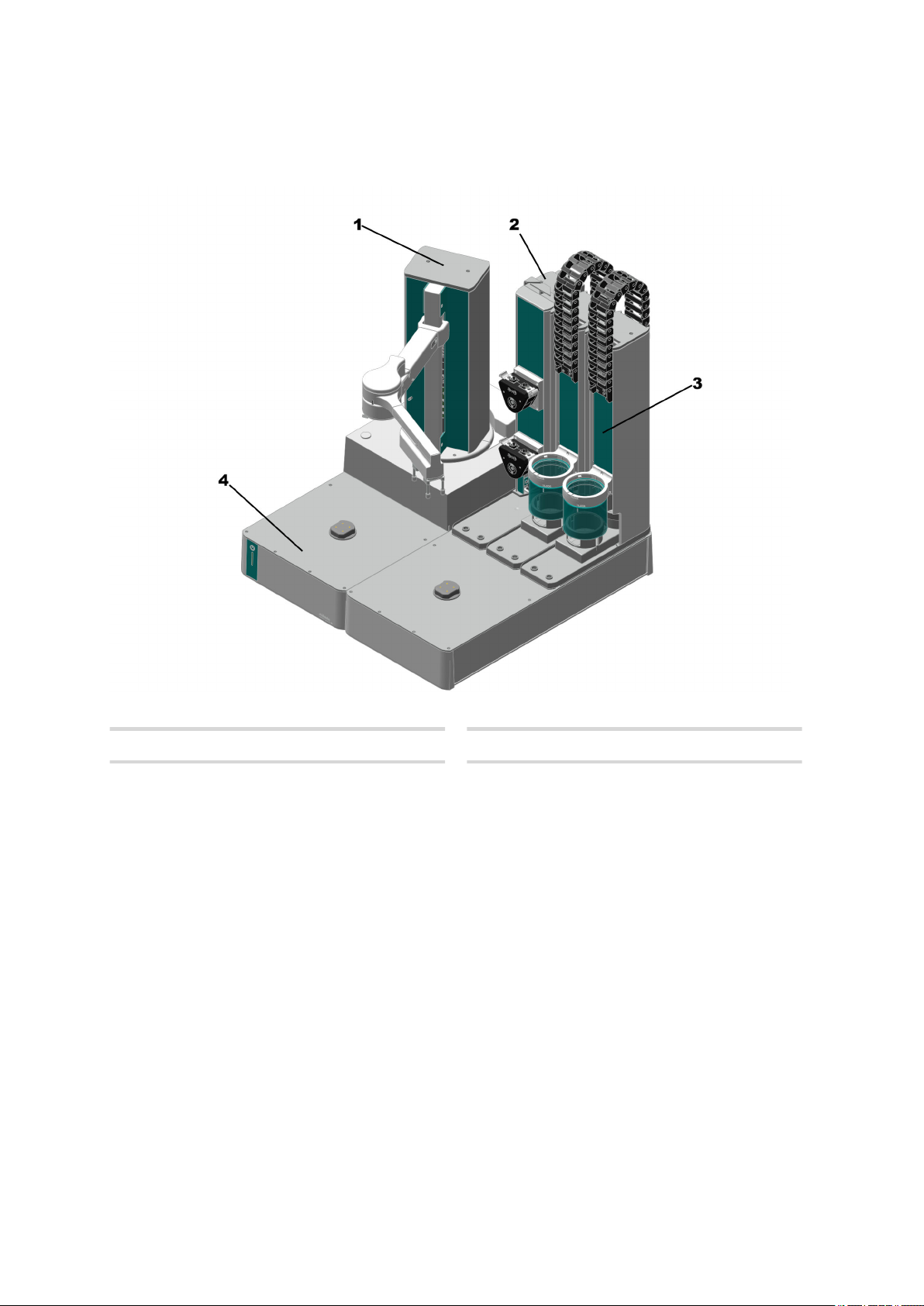
3.2 Overview – OMNIS Sample Robot Pick&Place S
Figure 1 OMNIS Sample Robot Pick&Place S
Main module
1
Pick&Place module
3
Pump module
2
Rack base
4
16
■■■■■■■■
Page 25

■■■■■■■■■■■■■■■■■■■■■■
Functional description
3.3 Overview – OMNIS Sample Robot Pick&Place M
Figure 2 OMNIS Sample Robot Pick&Place M
Main module
1
Pick&Place module
3
Pump module
2
Rack base
4
■■■■■■■■
17
Page 26
Overview – OMNIS Sample Robot Pick&Place L
■■■■■■■■■■■■■■■■■■■■■■
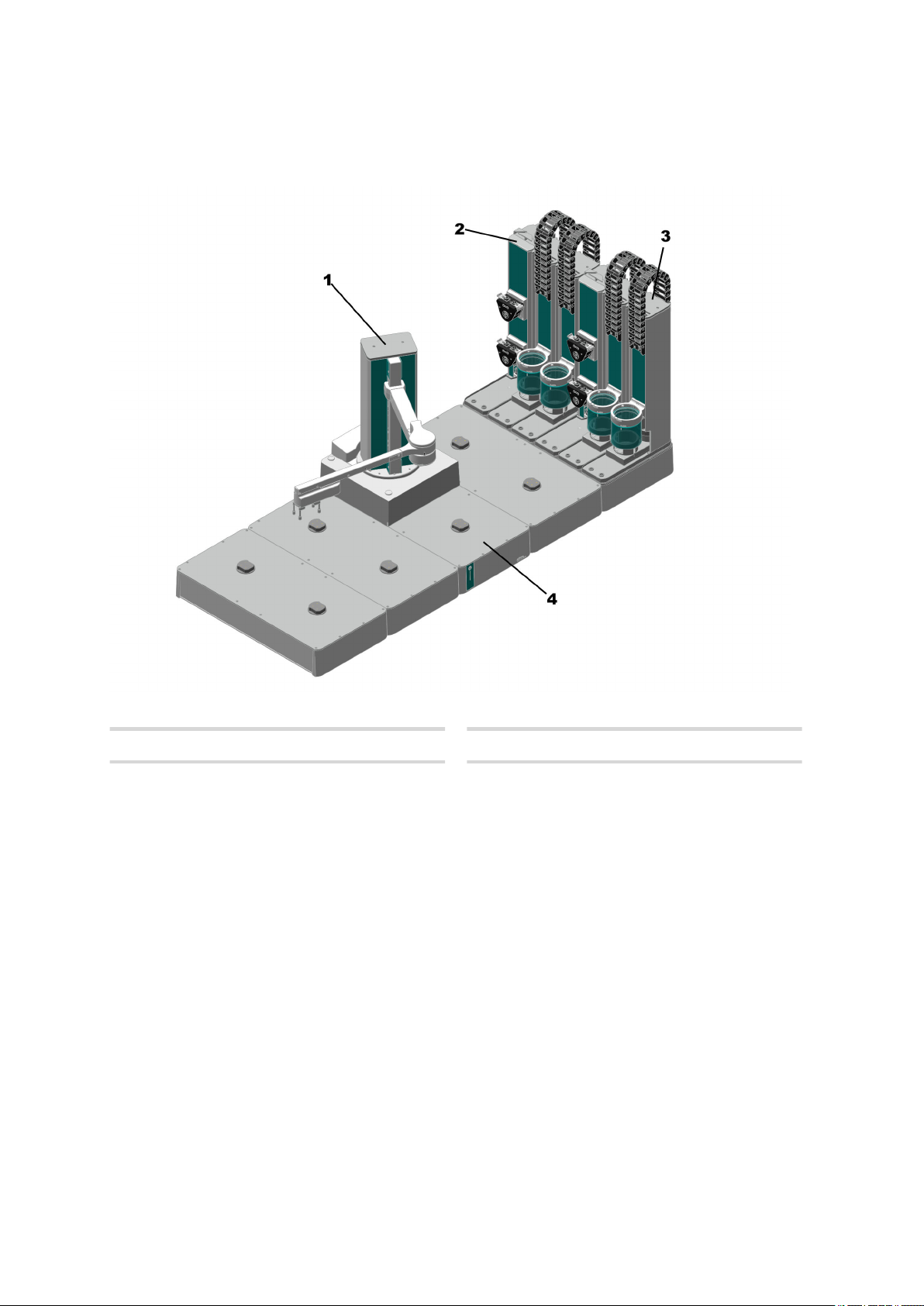
3.4 Overview – OMNIS Sample Robot Pick&Place L
Figure 3 OMNIS Sample Robot Pick&Place L
Main module
1
Pick&Place module
3
Pump module
2
Rack base
4
18
■■■■■■■■
Page 27

■■■■■■■■■■■■■■■■■■■■■■
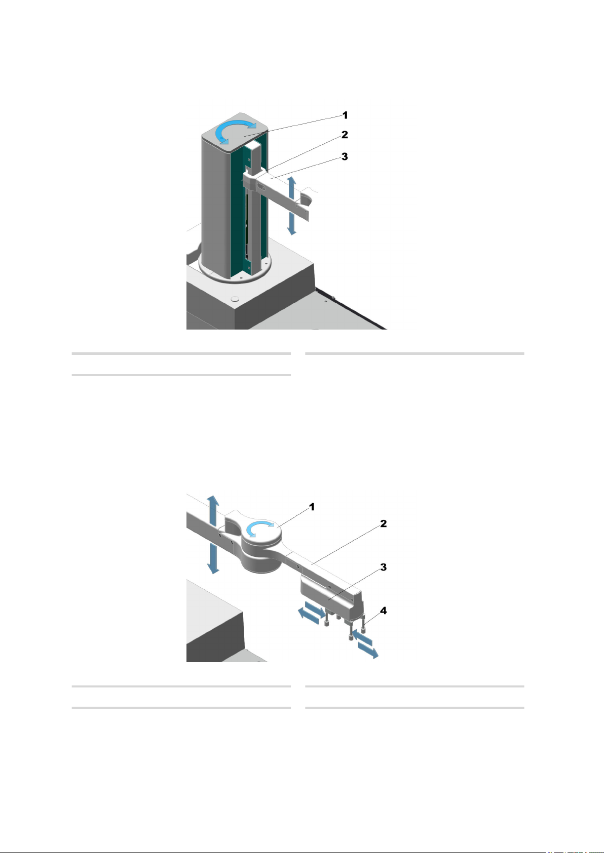
3.4.1 Main module Pick&Place – Overview
Functional description
Figure 4 Main module Pick&Place – General overview
Main lift
1
Lift arm
3
Gripper arm 3 - 5 Robot arm
5
Gripper
6
Arm holder
2
Arm joint
4
Gripper fingers
7
The main lift (4-1) is located on the main module Pick&Place.
The arm holder (4-2) connects the lift arm (4-3), the arm joint (4-4) and
the gripper arm (4-5) with the main lift. The gripper fingers (4-7) are
mounted on the gripper (4-6).
■■■■■■■■
19
Page 28
Overview – OMNIS Sample Robot Pick&Place L
3.4.1.1 Main lift – Overview
Figure 5 Main lift – Movement capacity
■■■■■■■■■■■■■■■■■■■■■■
Main lift
1
Lift arm
3
3.4.1.2
The lift arm (5-3) can be moved up and down along the main lift (5-1)
with the help of the arm holder (5-2).
The main lift (5-1) can be rotated to the left and right.
Gripper arm – Overview
2
Arm holder
20
Arm joint
1
Gripper
3
■■■■■■■■
Figure 6 Gripper arm – Movement capacity
Gripper arm
2
Gripper fingers
4
Page 29

■■■■■■■■■■■■■■■■■■■■■■
The gripper arm as a whole is moved up and down by the main lift.
With the arm joint (6-1), the gripper arm (6-2) can be turned to the left
and to the right. The gripper (6-3) can open and close the gripper fingers
(6-4), in order to pick up and hold beakers.
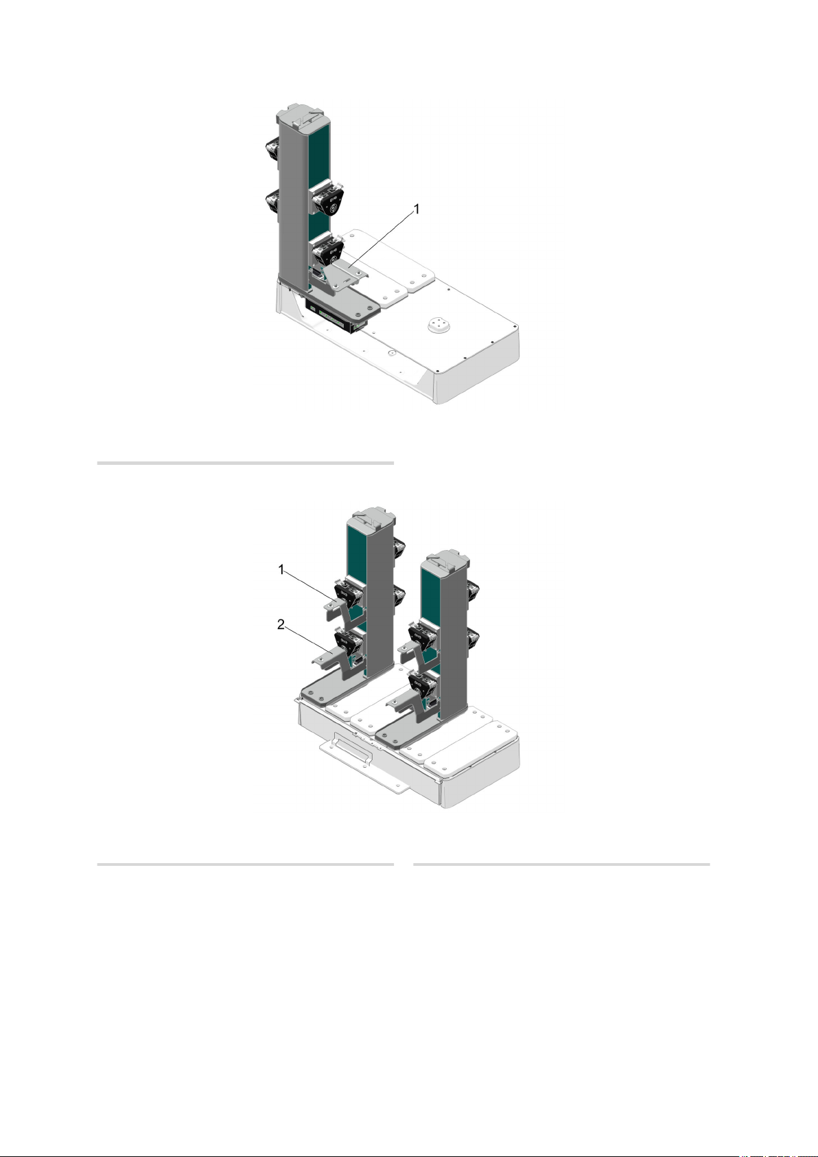
3.4.2 Pick&Place module – Overview
NOTICE
Extension versions
Up to 4 Pick&Place modules can be installed per OMNIS Sample
Robot.
In addition, if required, 1 holder for homogenizers (Polytron PT 1300
D) can be mounted on the front of the Pick&Place module.
Front
Functional description
Guide chain
1
Safety shield
3
Slide
5
Figure 7
Front – Pick&Place module
Lift tower
2
Collection tray
4
Titration head holder
6
On each Pick&Place module there is a slide (7-5) for positioning the sample beakers under the titration head.
■■■■■■■■
21
Page 30
Overview – OMNIS Sample Robot Pick&Place L
At both slide positions (7-5) (front and rear), the titration head holder
(7-6) can be moved downwards via the lift tower (7-2) so that the safety
shield (7-3) encases the sample beaker.
A titration head that fits the sample beaker to be used can be utilized in
the titration head holder (7-6). The titration head contains sensors, dosing
tips, cleaning accessories (and occasionally a rod stirrer or homogenizer)
that are required for the measurement.
Rear
■■■■■■■■■■■■■■■■■■■■■■
Drain nozzle
1
Figure 8 Rear – Pick&Place module
Distributor
2
At the rear of the Pick&Place module there is a drain nozzle (8-1) to which
a tubing is connected via a tubing adapter. Any liquid that may escape will
be routed through this tubing into the waste canister. In case of an error,
this protects the Pick&Place module from damage.
The distributor (8-2) that is used for connecting the rinsing tubing and
aspiration tubing is fitted on the back panel of the Pick&Place module.
Option for working with a homogenizer (Polytron PT 1300
D)
A homogenizer (Polytron PT 1300 D) (9-1) can be inserted in the titration
head (9-3) for applications which require homogenization of the sample.
A holder for homogenizers has to be mounted for guiding the homogenizer (9-2). For further information, see Inserting and equipping the
titration head.
22
■■■■■■■■
Page 31
■■■■■■■■■■■■■■■■■■■■■■
Functional description
Figure 9 Front – Pick&Place module with holder for homogenizer (Poly-
Holder for homogenizer (Polytron PT
1
1300 D)
Titration head
3
tron PT 1300 D)
Polytron PT 1300 D
2
■■■■■■■■
23
Page 32

Overview – OMNIS Sample Robot Pick&Place L
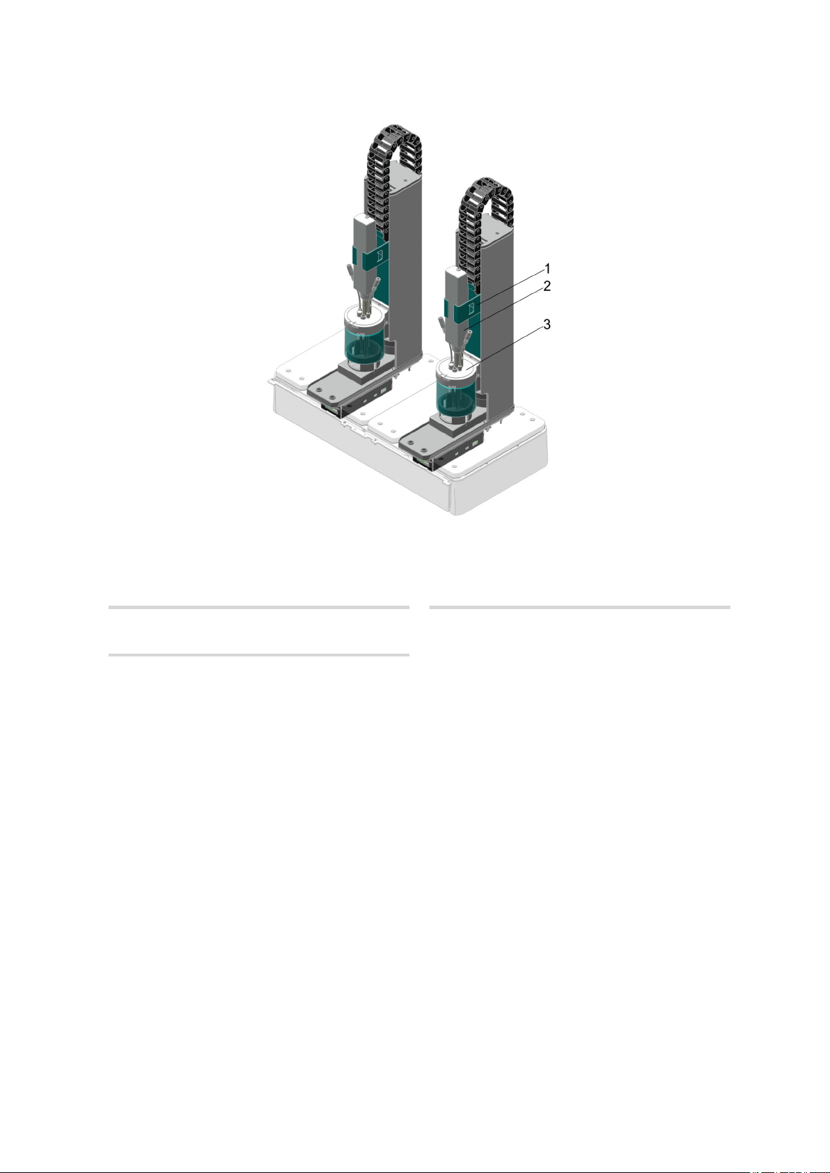
3.4.3 Peristaltic pump module – Overview
NOTICE
Extension versions
2 or 4 pumps can be mounted per pump module. In the case of the
two-way variant, the pumps are mounted on the front only and numbered 1 and 2. In the case of the four-way variant, 2 additional
pumps are mounted on the rear and numbered 3 and 4. Arrows indicating inlet and outlet are also to be found above each peristaltic
pump next to the numbering.
Optionally, 2 additional lid trays can be installed, e.g., for applications
with covered sample beakers such as volumetric Karl Fischer titration.
Front
■■■■■■■■■■■■■■■■■■■■■■
24
Tubing organizer
1
Peristaltic pumps
3
■■■■■■■■
Figure 10
Front – Peristaltic pump module
Housing
2
Page 33

■■■■■■■■■■■■■■■■■■■■■■
Functional description
Rear
Figure 11 Rear – Peristaltic pump module
Tubing organizer
1
Drain nozzle
3
Peristaltic pumps
2
2 or 4 peristaltic pumps (11-2) can be fitted on each peristaltic pump
module. 2 peristaltic pumps each can be used to rinse and clean the sensors in a Pick&Place module.
A tubing organizer (10-1) is located on the top side of the peristaltic
pump module to ensure orderly placement and secure fastening of the
connected tubing.
A drain nozzle (11-3) to which a tubing is connected via a tubing adapter
can be found at the rear of the peristaltic pump module. Any liquid that
may escape will be routed through this tubing into the waste canister. In
case of an error, this protects the pump module against damage.
Option for working with covered sample beakers
For applications where the sample needs to be protected from environmental influences for example, the sample beakers can be closed with lids.
To store these lids during analysis, different lid trays can be installed that
offer space for 2 to 4 lids (depending on the product version of the
OMNIS Sample Robot Pick&Place).
■■■■■■■■
25
Page 34
Overview – OMNIS Sample Robot Pick&Place L
Figure 12 Front – Peristaltic pump module with lid tray for OMNIS
■■■■■■■■■■■■■■■■■■■■■■
Sample Robot S
1
Lid tray
Figure 13 Front – Peristaltic pump module with lid trays for OMNIS
Sample Robot M / L
26
Top lid tray
1
■■■■■■■■
Bottom lid tray
2
Page 35

■■■■■■■■■■■■■■■■■■■■■■
3.4.3.1 Overview – Peristaltic pump
Figure 14 Peristaltic pump
Functional description
Press clamp
1
Inlet
3
Outlet
2
LED
4
Supply and drainage tubing is connected at the inlet (14-3) and outlet
(14-2) of the peristaltic pump.
A pump tubing is located in the interior of the peristaltic pump between
the inlet and the outlet that is pinched off by four rollers. The conveyance
medium is pumped through the system by this volume displacement.
The press clamp (14-1) protects the pump tubing against external influences. The press clamp can be dismantled to check the pump tubing and to
replace it if necessary.
The LED (14-4) displays the status of the peristaltic pump.
■■■■■■■■
27
Page 36

Overview – OMNIS Sample Robot Pick&Place L
3.4.4 Rack base – Overview
Figure 15 Rack base of an OMNIS sample robot
■■■■■■■■■■■■■■■■■■■■■■
Rack base
1
3.4.4.1
On each rack base (15-1), up to 2 sample racks can be inserted on the
rack holders (15-2).
The system uses the sensors in the rack holder to detect which sample
rack type (if any) is present.
Sample rack – Overview
Rack holder
2
28
Sample beaker
1
Transport handles
3
■■■■■■■■
Figure 16 Sample rack
Sample position
2
Spout hole
4
Page 37

■■■■■■■■■■■■■■■■■■■■■■
The sample beakers (16-1) are stored in the sample positions (16-2) in the
sample rack.
The transport handles (16-3) allow for the sample rack to be transported
by hand so that it can be set down on and removed from the rack holder
of the rack base. Several empty sample racks can be stacked on top of one
another on the transport handles.
The sample rack contains rinsing holes for emptying liquids in case of
overflows and for cleaning.
NOTICE
Cleaning
The sample rack is not dishwasher-safe.
Table 6 Sample rack versions
Art. no. Beaker volume Number of beakers
Functional description
6.02041.010 250 mL 9
6.02041.020 200 mL 9
6.02041.030 120 mL 16
6.02041.040 75 mL 25
3.5 Sample Robot Pick&Place – Functional description
The Sample Robot Pick&Place is comprised of the following components:
■ Main module Pick&Place
■ Pick&Place module
■ Peristaltic pump module
■ Rack base
■ Module base
The OMNIS Sample Robot System is used for the automatic measurement
of different organic and inorganic samples.
The samples are stored, transported and processed through the components individually integrated in the system.
■■■■■■■■
29
Page 38

Sample Robot Pick&Place – Functional description
■■■■■■■■■■■■■■■■■■■■■■
3.5.1 Main module Pick&Place – Functional description
All of the attached modules in the OMNIS Sample Robot System are supplied with electricity through the main module Pick&Place.
The main lift with gripper and gripper arm is fastened to the main module
Pick&Place.
The gripper is used for transporting the sample beakers out of the sample
racks and into the processing stations intended for this purpose. Once the
processing of the samples has been completed, the gripper removes the
sample beakers out of the processing stations once again and transports
them back into the previously removed sample rack.
The control hardware is integrated in the interior of the main module
Pick&Place.
3.5.2 Pick&Place module – Functional description
The samples in the OMNIS sample robot system are analyzed on the
Pick&Place module.
The sample beakers are transported by the sample robot into the front
sample position of the Pick&Place module. After the sample beaker has
been put into place, the slide with the sample beaker moves under the
titration head and the lift moves downward.
The sensors installed in the titration head analyze the sample.
After completion of the measurement, the sensors are cleaned with one
of the pumps that are integrated in the pump module. The solution that is
generated during this process is aspirated by an additional pump of the
pump module and the lift with the sensors rises.
Afterwards the slide moves back out again and the sample beaker is
removed by the sample robot.
3.5.3 OMNIS peristaltic pump module – Functional description
2 or 4 peristaltic pumps are integrated on the peristaltic pump module.
2 peristaltic pumps are assigned to each workstation in the OMNIS sample
robot system.
The upper peristaltic pump (numbered with 1 or 3) rinses off the sensors
in the Pick&Place modules with solvent after the analysis of a sample. For
this purpose, the solvent is aspirated from the rinsing canister through the
peristaltic pump. If required, these pumps can also be used to dilute a
sample with solvent or to bring it into solution prior to an analysis.
30
The lower peristaltic pump (numbered with 2 or 4) aspirates the remaining
solution out of the sample beaker during and after the rinsing procedure
and routes it to the waste canister.
■■■■■■■■
Page 39

■■■■■■■■■■■■■■■■■■■■■■
Optionally, up to 2 lid trays can be installed on the pump module. The lid
that was removed from the sample beaker is parked on the lid tray until it
is needed again to seal the sample beaker.
If malfunctions occur at the peristaltic pump, this will be displayed via LED
at the peristaltic pump.
3.5.3.1 Functional description – Peristaltic pump
The peristaltic pump operates in accordance with the volume displacement principle.
The pump tubing in the interior connects the inlet and the outlet of the
peristaltic pump.
This pump tubing is pinched off by four internal rollers. Media are aspirated in and out by this squeezing of the pump tubing and the volume displacement that results from it.
3.5.4 Rack base – Functional description
The rack base is the skeletal structure for the sample robot.
The sample racks in which the sample beakers are located are stored on
the rack holders of the rack base. The rack holders contain sensors that
automatically detect which sample rack type is currently located on the
individual rack base.
Functional description
The OMNIS sample robot system uses the sample rack type to detect
which type of sample beakers are located in the sample rack. This information is passed along to the control which sets the gripper to the respective size of the sample beakers.
If a sample rack that is still to be approached by the sample robot is
removed, this is detected by the rack holders and passed along to the
OMNIS sample robot system. This sample rack will no longer be
approached by the sample robot and the absence of the sample rack will
be displayed in the control.
■■■■■■■■
31
Page 40

OMNIS Sample Robot – Indicators and controls
■■■■■■■■■■■■■■■■■■■■■■
3.6 OMNIS Sample Robot – Indicators and controls
Figure 17 OMNIS Sample Robot – Indicators and controls
On/off switch
1
Status display
2
Multi-colored
Indicators
The status of the instrument is displayed with the status display (17-2)
using different colors System – Signals (see chapter 3.1.1, page 14).
Controls
The on/off switch (17-1) is used for the hardware-side operation of the
OMNIS Sample Robot.
Table 7
Behavior of the on/off switch
Pressure duration Acoustic signal Functions on the sample
robot
Short pressing (1 to 5 s)
Beep after 1 s
Switching on the instrument
Shutting down the instrument
Long pressing (approx. 5 s) Double-beep Gripper opens (if available)
32
■■■■■■■■
Page 41

■■■■■■■■■■■■■■■■■■■■■■
3.7 Main module – Connectors
NOTICE
Symbol labeling
Observe the connector symbols when connecting the instruments.
Functional description
Figure 18 Connectors – Main module Pick&Place
Human Interactive Device (HID)
1
Metrohm Device Link (MDL)
3
Local Area Network (LAN)
2
Power socket
4
■■■■■■■■
33
Page 42

Checking the delivery
4 Transport and storage
4.1 Checking the delivery
Immediately upon arrival of the merchandise, check the shipment against
the delivery note to ensure completeness and absence of damage.
4.2 Storing the packaging
The product is supplied in extremely protective packaging together with
the separately packed accessories. Keep this packaging, as only this
ensures safe transportation of the product.
4.3 Lifting the sample robot
■■■■■■■■■■■■■■■■■■■■■■
Avoid lifting the sample robot after the initial installation whenever possible. The bigger M and L versions in particular need to be adjusted again
after transportation.
If it is necessary to lift the sample robot, try to avoid a sag by lifting the
system on all four sides. Take the total weight of the system into account.
Check the positioning accuracy of the sample robot after placing the sample robot down. If inaccuracies occur, Metrohm support will assist you.
34
■■■■■■■■
Page 43

■■■■■■■■■■■■■■■■■■■■■■
5 Installation
5.1 Installation by Metrohm
NOTICE
Installation of the products
As a basic rule, the installation of the system and of the new products
and modules is handled by trained and instructed specialists from the
Metrohm Company and/or its representative.
5.2 Sample robot setting up
Installation
The product has been developed for operation indoors and may not be
used in explosive environments.
Place the instrument in a location of the laboratory which is suitable for
operation and provides protection against corrosive atmosphere and contamination by chemicals.
The sample robot needs a horizontal and plane table that is stable and
free of vibrations for a precise mode of operation. The work surface may
not bend under a load of 60 kg.
Observe the dimensions and weights of the individual products and modules that are part of the complete system. You will find this information in
the "Technical specifications" section.
Protect the product against excessive temperature fluctuations and direct
sunlight.
The power cord has to be accessible while operating and must not be
replaced by an impermissible cable.
■■■■■■■■
35
Page 44

Replacing the seal of the sample beaker lid
■■■■■■■■■■■■■■■■■■■■■■
5.3 Replacing the seal of the sample beaker lid
The appropriate seals must be placed on sample beaker lids to tightly seal
sample beakers. These seals must not be damaged.
NOTICE
We recommend replacing the seal of the sample beaker lid approx.
every 6 months.
The standard seals were designed for aqueous applications and Karl
Fischer titrations. If more aggressive solvents such as chlorobenzene
or glacial acetic acid are used, we recommend the more resistant
seals.
Table 8 List of sample beakers with seals for sample beaker lids
Art. no. Designation Beaker size
6.02710.000 Lid for sample beaker 75 mL (P&P) with
standard seals
6.02710.030 Lid for sample beaker 75 mL (P&P) with
resistant seals
6.02710.010 Lid for sample beaker 120 mL (P&P) with
standard seals
6.02710.040 Lid for sample beaker 120 mL (P&P) with
resistant seals
6.02710.020 Lid for sample beaker 250 mL (P&P) with
standard seals
6.02710.050 Lid for sample beaker 250 mL (P&P) with
resistant seals
75 mL
75 mL
120 mL
120 mL
250 mL
250 mL
NOTICE
The accessories for the respective product version can be obtained
either on the Internet at http://www.metrohm.com or via your
regional Metrohm representative.
36
■■■■■■■■
Page 45
■■■■■■■■■■■■■■■■■■■■■■
Installation
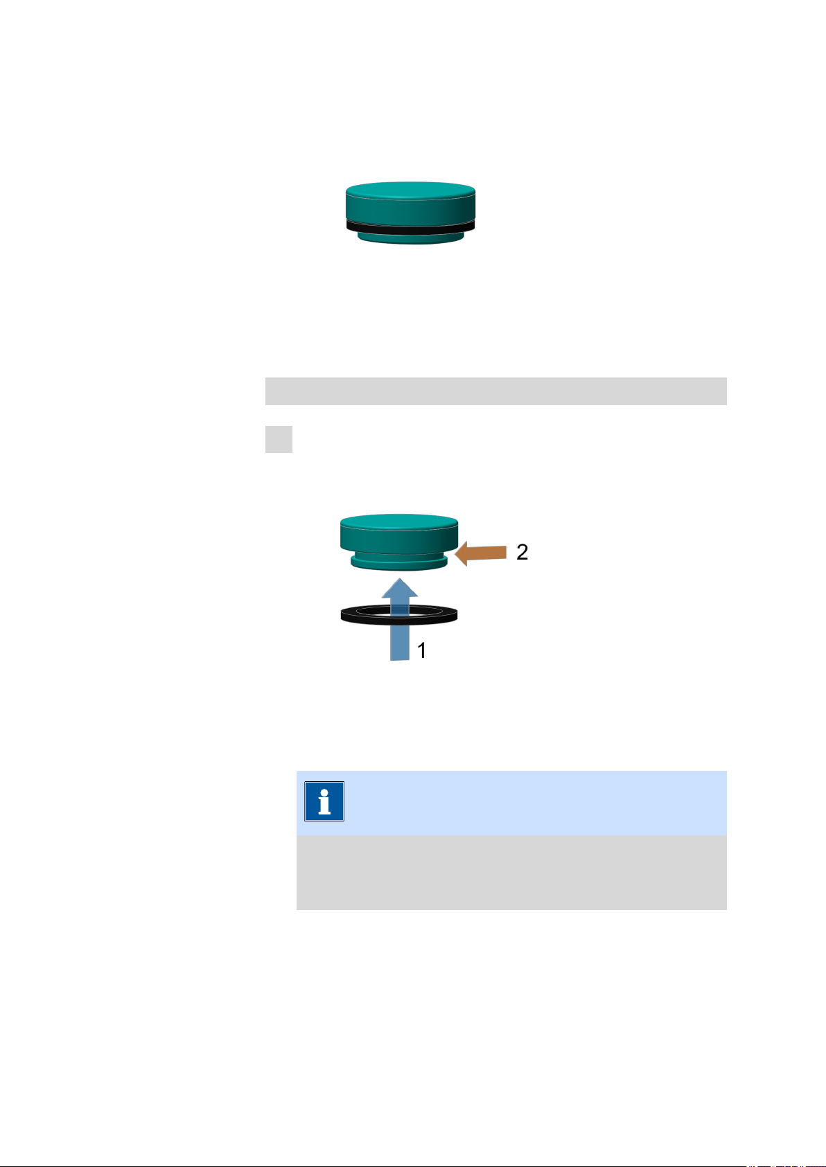
Figure 19 Sample beaker lid with seal for sample beaker lid (complete)
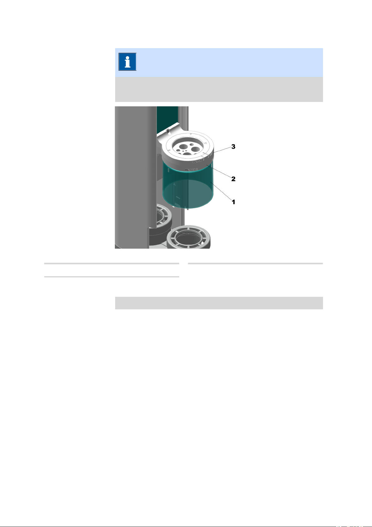
Placing the seal onto the sample beaker lid
1
Placing and fitting the lid seal
Figure 20 Placing the rubber seal onto the lid
Slide the rubber seal from below over the lid bottom so that it sits
neatly in the prefabricated groove.
NOTICE
Make sure that the rubber seal fits the groove perfectly. You
might need to stretch the rubber seal and press it into the
groove.
■■■■■■■■
37
Page 46

Inserting and equipping the titration head
■■■■■■■■■■■■■■■■■■■■■■
Removing the seal of the sample beaker lid
Pull the lid seal down over the lid bottom and remove it.
1
5.4 Inserting and equipping the titration head
NOTICE
The titration head has the markings "LOCK" for closed and "UNLOCK"
for open, also see Replacing the titration head (see chapter 8.4.3,
page 73).
38
Figure 21 Inserting the titration head (general)
Titration head
1
Markings "LOCK" and "UNLOCK"
3
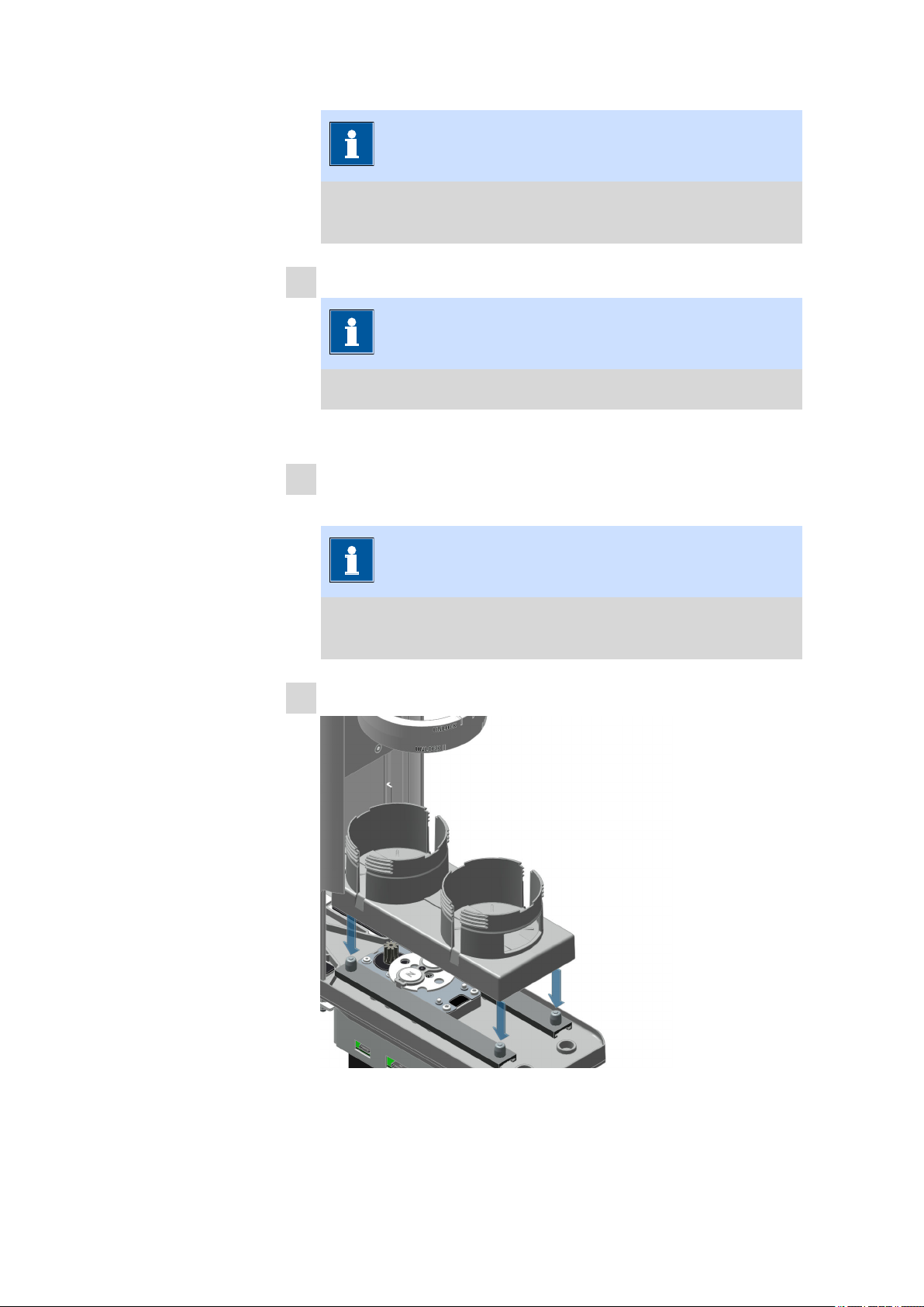
Prerequisites:
■ The sample robot is switched off.
■ All of the sensors in the titration head are dismounted.
■■■■■■■■
2
Inserting the titration head
Titration head holder
Page 47

■■■■■■■■■■■■■■■■■■■■■■
■ The safety shield is dismounted.
1
Inserting the titration head
Insert the titration head (21-1) from below into the titration head
holder (21-2).
NOTICE
In case a rod stirrer is used:
The marked opening (triangle or arrow) for inserting the rod stirrer on the titration head should be located as close as possible to
the tower of the Pick&Place module. This ensures that the rod
stirrer is in a central position and takes up only a small amount
of space.
2
Fastening the titration head
Installation
Figure 22 Fastening the titration head
Rotate the titration head by hand until the marking points to "LOCK".
■■■■■■■■
39
Page 48

Inserting and equipping the titration head
Equipping the titration head for titration
Figure 23 Positions of the components in the titration head (titration
■■■■■■■■■■■■■■■■■■■■■■
with rod stirrer)
Position for the spray nozzles or rins-
1
ing nozzles
Position for the aspiration tip
3
Position for the rod stirrer
5
Equipping the titration head for titration
Prerequisites:
■ The sample robot is switched off.
■ The required titration head is mounted.
1
Position for the electrode
2
Position for the preinstalled dosing tips
4
for connecting dosing tubing
Mounting the rinsing tubing
Insert the spray nozzles from above into the positions intended for
this purpose and mount the rinsing tubing.
NOTICE
40
During insertion, take care to ensure that the spray nozzles do
not touch the rod stirrer because otherwise this could lead to
jamming of the stirrer.
■■■■■■■■
Page 49

■■■■■■■■■■■■■■■■■■■■■■
2
Inserting the electrode
Insert the electrode from above into the position intended for this
purpose.
3
Mounting the aspiration tubing
Insert the aspiration tip from above into the position intended for this
purpose and mount the aspiration tubing.
If necessary, shorten the aspiration tip to the desired length afterwards.
4
Mounting the dosing tubing
Mount the dosing tubing onto the preinstalled dosing tips.
5
Inserting the rod stirrer
Insert the rod stirrer from above into the position intended for this
purpose, place the corresponding stirring propeller from below onto
the rod stirrer coupling and connect the cable of the rod stirrer to the
MDL socket of the main module.
Installation
NOTICE
This step is not necessary if the Pick&Place module involved is
the version with the built-in magnetic stirrer (2.1014.0110).
■■■■■■■■
41
Page 50

Inserting and equipping the titration head
Equipping the titration head for Karl Fischer titration
Figure 24 Positions of the components in the KF titration head
■■■■■■■■■■■■■■■■■■■■■■
Buret tip for titrant
1
Preinstalled dosing tip with antidiffusion
valve
Stopper or aspiration tip
3
Screw nipples (4 pieces)
5
Screw nipple (6.2730.030)
Equipping the titration head for KF titration
Prerequisites:
■ The sample robot is switched off.
■ The required titration head is mounted.
1
Dosing tip for reagent (Solvent)
2
Preinstalled dosing tip with antidiffusion
valve
Double Pt wire electrode
4
Double Pt wire electrode, for KF sample
changers incl. electrode cable (6.0340.000)
Titration head for KF titration
6
(6.01403.020)
Inserting the stopper or aspiration tip
Insert the stopper (24-3) into the screw nipple at the back (close to
the Pick&Place module tower).
42
■■■■■■■■
Page 51

■■■■■■■■■■■■■■■■■■■■■■
NOTICE
Depending on the application, the stopper can also be replaced
by an aspiration tip to aspirate the solution after the titration.
The aspiration tip might need to be shortened to the desired
length and an aspiration tubing must be mounted.
2
Inserting the buret tip for the titrant
Insert the buret tip into the screw nipple on the left, mount the titration tubing and screw it tight.
NOTICE
The titration tip should be located just above the stirring bar, but
should not impede it.
Installation
3
Inserting the dosing tip for the reagent (Solvent)
Insert the dosing tip (24-2) into the screw nipple on the right, mount
the dosing tubing and screw it tight.
NOTICE
The dosing tip should be located just above the stirring bar, but
should not impede it.
4
Inserting the electrode
Insert the double Pt wire electrode (24-4) with the electrode cable
into the screw nipple at the front and screw it tight.
■■■■■■■■
43
Page 52

Mounting the safety shield
5.5 Mounting the safety shield
WARNING
Working without a safety shield
A risk of injury exists when working without a safety shield mounted.
■ Never operate the sample robot without a safety shield.
■ Before beginning work, make sure that all of the protective devi-
ces are mounted on the sample robot and operational.
■ Always wear personal protective equipment when working with
the sample robot.
NOTICE
■■■■■■■■■■■■■■■■■■■■■■
The safety shield has the designations "LOCK" for closed and
"UNLOCK" for open.
Figure 25 Inserting the safety shield
44
Safety shield
1
Markings "LOCK" and "UNLOCK"
3
■■■■■■■■
Titration head holder
2
Page 53

■■■■■■■■■■■■■■■■■■■■■■
Mounting the safety shield
Prerequisites:
■ The sample robot is switched off
1
Inserting the safety shield
Insert the safety shield (25-1) from the bottom into the titration head
holder (25-2).
2
Fastening the safety shield
Installation
Figure 26 Fastening the safety shield
Rotate the safety shield clockwise until the marking points to
"LOCK".
■■■■■■■■
45
Page 54

Connecting the tubing to the distributor of the Pick&Place module
■■■■■■■■■■■■■■■■■■■■■■
5.6 Connecting the tubing to the distributor of the Pick&Place module
Rinsing tubing
1
Distributor
3
Outlet tubing
5
Figure 27 Connecting the tubing to the distributor
Aspiration tubing
2
Rinsing tubing
4
Connecting the tubing to the distributor
Prerequisites:
■ The sample robot is switched off
1
Connecting the rinsing tubing
Manually tighten or plug in the three rinsing tubings (27-1) in the M3
bore holes of the distributor (27-3).
NOTICE
The rinsing tubings lead to the spray nozzles of a titration head
in the Pick&Place module.
46
■■■■■■■■
Page 55

■■■■■■■■■■■■■■■■■■■■■■
2
Connecting the aspiration tubing
Manually tighten the aspiration tubing (27-2) in the M3 bore hole of
the distributor.
3
Connecting the rinsing tubing
Remove the union nut.
Pull the end of the tubing over the connection nipple of the distributor and fasten in place with the union nut.
NOTICE
The rinsing tubing (27-4) leads to the rinsing pump (Pump 1 or
Pump 3) and can be cut to the correct length.
4
Connecting the outlet tubing
Remove the union nut.
Installation
Pull the end of the tubing over the connection nipple of the distributor and fasten in place with the union nut.
NOTICE
The outlet tubing (27-5) leads to the aspiration pump (Pump 2
or Pump 4) and can be cut to the correct length.
■■■■■■■■
47
Page 56

Connecting the drainage tubing
5.7 Connecting the drainage tubing
Connecting and placing the drainage tubing
1
■■■■■■■■■■■■■■■■■■■■■■
Push the tubing adapter (1) in an angle of 30 degrees (see illustration) onto the drain nozzle.
2
3
48
■■■■■■■■
Page 57

■■■■■■■■■■■■■■■■■■■■■■
Plug the drainage tubing (2) in the tubing adapter and guide it
through the tubing duct (3) to the waste canister (red line). Take care
that the tubings are not bent upwards to prevent liquids from backing up.
5.8 Connecting the inlet and outlet tubing
Installation
Outlet tubing
1
Connecting element
3
Figure 28 Connecting the inlet and outlet tubing
Inlet tubing
2
Peristaltic pump
4
Connecting the inlet and outlet tubing of the peristaltic
pump
Prerequisites:
■ The sample robot is switched off
Plug the inlet tubing (28-2) into the connecting element (28-3) of
1
the peristaltic pump (28-4) by hand and rotate clockwise until it fits
closely.
■■■■■■■■
49
Page 58

Connecting/Disconnecting the power cord
■■■■■■■■■■■■■■■■■■■■■■
NOTICE
The tubing connections at the inlet and outlet of the peristaltic
pump correspond to the "Luer lock system".
The peristaltic pump rotates clockwise.
Connect the outlet tubing (28-1) following the same procedure.
2
Place the tubing without squeezing it onto the top side by using the
3
tubing organizer. Make sure that the tubing is positioned as close as
possible to the housing.
The pump operates the aspiration tubing and the three rinsing tubings
5.9 Connecting/Disconnecting the power cord
WARNING
Electric shock from electrical potential
Risk of injury by touching live components or through moisture on
live parts.
■ Never open the housing of the product.
■ Protect live parts (e.g. power supply unit, power cord, connection
sockets) against moisture.
■ If you suspect that moisture has gotten into the product, discon-
nect the product from the energy supply. Then notify Metrohm
Service.
■ Only personnel who have been issued Metrohm qualification may
perform service and repair work on electrical and electronic components.
Connecting the power cord
Accessories
Use power cord according to specifications under "Technical specifications".
50
■■■■■■■■
Page 59

■■■■■■■■■■■■■■■■■■■■■■
Installation
Power cord with a maximum length of 2 m, three-core with IEC 60320
instrument plug type C13. Conductor cross-section 3x 0.75 mm2 / 18
AWG.
Power plug according to customer requirements (6.2122.XX0), designed
for a minimum of 10 A.
1
Plugging in the power cord
■ Plug the power cord into the product's power socket.
■ Connect the power cord to the energy supply.
NOTICE
To switch off the product, you must unplug the power cord from
the energy supply.
■■■■■■■■
51
Page 60

Initial start-up by Metrohm
6 Initial start-up
6.1 Initial start-up by Metrohm
NOTICE
Initial start-up of the product
As a basic rule, the initial start-up of the system and of the new products and modules is handled by trained and instructed specialists from
the Metrohm Company and/or its representative.
■■■■■■■■■■■■■■■■■■■■■■
52
■■■■■■■■
Page 61

■■■■■■■■■■■■■■■■■■■■■■
Operation and control
7 Operation and control
7.1 Operation
NOTICE
Operating via the control software
The product can be operated using the commands of the control
software.
Additional information can be found in the software help .
7.2 Switching the OMNIS sample robot on and off
Switching the OMNIS sample robot on and off
The on/off switch
robot.
1
Switching the OMNIS sample robot on
Press the on/off switch for one second until the single acoustic
signal is heard.
The status display (see "Indicators", page 32) is lit up yellow until it is
paired with the OMNIS Software.
As soon as the sample robot is paired with the OMNIS Software, the
color of the status display switches to green and the sample robot is
ready for operation.
2
Switching the OMNIS sample robot off
Press the on/off switch for one second until the single acoustic
signal is heard.
is located on the main module of the sample
The status display goes out and the sample robot is switched off.
■■■■■■■■
53
Page 62

Opening the gripper manually
NOTICE
Additional information on the controls, see OMNIS Sample Robot –
Indicators and controls (see chapter 3.6, page 32).
7.3 Opening the gripper manually
CAUTION
Unsecured sample beakers
If the gripper is opened, then unsecured sample beakers can cause
injuries and property damage to the instrument.
■ Wear personal protective equipment.
■ Always hold the sample beaker in one hand when the gripper is
being opened manually.
■■■■■■■■■■■■■■■■■■■■■■
54
On/off switch
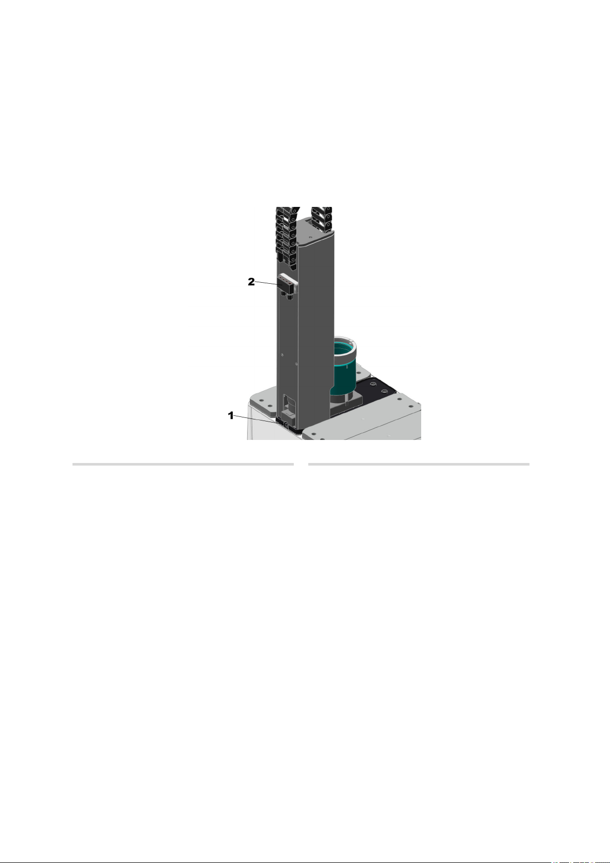
1
■■■■■■■■
Figure 29 Main module Pick&Place, front
LED
2
Opening the gripper manually
Prerequisites:
■ The sample robot stands still.
Hold the sample beaker in one hand.
1
Page 63

■■■■■■■■■■■■■■■■■■■■■■
Hold the on/off switch (29-1) pressed down for five seconds until a
2
dual beep is heard.
The gripper opens and the sample beaker can be removed.
7.4 Attaching and removing the sample rack
CAUTION
Utilization of non-authorized sample beakers
The use of non-authorized sample beakers in the
OMNIS Sample Robot System can lead to injuries and considerable
property damage.
■ Use only sample beakers that are authorized by Metrohm.
Operation and control
NOTICE
Because of the shape of the rack holder and the counterpart on the
sample rack, only one position exists at which the sample rack can be
properly placed on the rack base.
■■■■■■■■
55
Page 64

Attaching and removing the sample rack
Figure 30 Overview image – Attaching and removing the sample rack
■■■■■■■■■■■■■■■■■■■■■■
1
3
Rack base
Sample rack
Rack holder
2
Transport handles
4
Attaching a sample rack
1
Attaching a sample rack
Figure 31 Attaching a sample rack
56
Grip the sample rack (30-3) on the transport handles (30-4) with
both hands and set it down on the rack base (30-1).
■■■■■■■■
Page 65

■■■■■■■■■■■■■■■■■■■■■■
2
Pushing in the sample rack
Figure 32 Pushing in the sample rack
Operation and control
Push the sample rack towards the front until it is firmly seated on the
rack holder (30-2).
NOTICE
A brief acoustic signal will sound as soon as the sample rack is
seated correctly on the rack base and the rack holder.
Removing the sample rack
Grip the sample rack on the transport handles with both hands and
1
remove it towards the top.
NOTICE
A brief acoustic signal will sound as soon as the sample rack has
been removed from the rack base and the rack holder.
■■■■■■■■
57
Page 66
General maintenance
8 Maintenance
8.1 General maintenance
The products require appropriate care. Excess contamination of the products may result in functional disruptions and a reduction in the service life
of the mechanics and electronics.
Only perform maintenance work that is described in this instruction. Contact the Metrohm service for further maintenance and repairing works.
Disconnect the product from the power grid prior to any maintenance and
cleaning.
Remove spilled chemicals and solvents immediately. Protect the plug connections in particular against contamination.
NOTICE
■■■■■■■■■■■■■■■■■■■■■■
The product is protected by design measures from being penetrated
by liquids.
CAUTION
Instrument damage due to removed covers
Damage of the instrument or malfunction by removing the housing
covers.
■ Never open the housing of the instrument when the power cord is
connected.
■ There are no parts inside the housing which may be serviced or
replaced by the user, unless this is explicitly described.
■ Only personnel who have been issued Metrohm qualification may
perform service and repair work on electric and electronic parts.
58
■■■■■■■■
Page 67

■■■■■■■■■■■■■■■■■■■■■■
Maintenance
WARNING
Electric shock from electrical potential
Risk of injury by touching live components or through moisture on
live parts.
■ Never open the housing of the product.
■ Protect live parts (e.g. power supply unit, power cord, connection
sockets) against moisture.
■ If you suspect that moisture has gotten into the product, discon-
nect the product from the energy supply. Then notify Metrohm
Service.
■ Only personnel who have been issued Metrohm qualification may
perform service and repair work on electrical and electronic components.
WARNING
Risk of injury due to lack of safety shield
Risk of injury when working without mounted safety shields.
■ Never operate instruments without safety shields.
■ Before beginning work, make sure that all the safety shields are
mounted correctly and are operational.
8.2 Maintenance agreement
Maintenance of the product is best carried out as part of an annual service
performed by specialist personnel from Metrohm. Shorter maintenance
intervals may be necessary if you frequently work with caustic and corrosive chemicals.
Metrohm Service offers every form of technical advice for maintenance
and service of all Metrohm products.
■■■■■■■■
59
Page 68

Cleaning the product
8.3 Cleaning the product
WARNING
Danger of poisoning and chemical burns from chemical hazardous substances
Poisoning and/or chemical burns by contact with aggressive chemical
substances.
■ Use only detergents that do not cause any unwanted side reac-
tions with the materials to be cleaned.
■ Clean contaminated surfaces.
■ Wear protective equipment.
■ Use exhaust equipment when working with vaporizing hazardous
substances.
■ Dispose of chemically contaminated materials (e.g. cleaning mate-
rial) properly.
■■■■■■■■■■■■■■■■■■■■■■
WARNING
Electric shock from electrical potential
Risk of injury by touching live components or through moisture on
live parts.
■ Never open the housing of the product.
■ Protect live parts (e.g. power supply unit, power cord, connection
sockets) against moisture.
■ If you suspect that moisture has gotten into the product, discon-
nect the product from the energy supply. Then notify Metrohm
Service.
■ Only personnel who have been issued Metrohm qualification may
perform service and repair work on electrical and electronic components.
Cleaning the surfaces of the product
Prerequisites
■ The product is disconnected from the power grid.
Clean the surfaces with a damp cloth.
1
60
■■■■■■■■
Page 69

■■■■■■■■■■■■■■■■■■■■■■
Maintenance
NOTICE
If the suspicion arises that liquids have found their way into the
product, disconnect the product from the power grid and contact your Metrohm Service.
NOTICE
Water or ethanol can be used as a cleaning medium.
NOTICE
The connectors at the rear of the product must only be cleaned
with a dry cloth.
8.3.1 Cleaning the Pick&Place module
WARNING
Harmful or irritant materials
There is an increased risk of injury through contact with chemical or
biological materials while cleaning the instrument.
■ Use detergents that do not cause any unwanted reactions with the
materials to be cleaned.
■ Always wear personal protective equipment when cleaning the
instrument.
Cleaning the surfaces of the Pick&Place module
Prerequisites
■ The instrument is disconnected from the power grid.
Remove dust and dirt from the Pick&Place module surface with a
1
damp cloth.
■■■■■■■■
61
Page 70
Cleaning the product
■■■■■■■■■■■■■■■■■■■■■■
NOTICE
The safety shield has the designations "LOCK" for closed and
"UNLOCK" for open.
Figure 33 Cleaning the safety shield
Safety shield
1
Markings "LOCK" and "UNLOCK"
3
Cleaning the safety shield
Prerequisites
Titration head holder
2
62
■■■■■■■■
Page 71

■■■■■■■■■■■■■■■■■■■■■■
■ The instrument is disconnected from the power grid.
1
Dismantling the safety shield
Maintenance
Figure 34 Dismantling the safety shield
■ Grip the safety shield (33-1) with one hand and rotate it counter-
clockwise until the marking points to "UNLOCK" (33-3).
■ Remove the safety shield downwards out of the titration head
holder (33-2).
2
Cleaning the safety shield
Remove dust and dirt from the safety shield with a damp cloth.
■■■■■■■■
63
Page 72

Cleaning the product
3
Inserting the safety shield
■■■■■■■■■■■■■■■■■■■■■■
Figure 35 Inserting the safety shield
Insert the safety shield from the bottom into the titration head
holder.
4
Fastening the safety shield
64
Figure 36 Fastening the safety shield
Rotate the safety shield clockwise until the marking points to
"LOCK".
■■■■■■■■
Page 73

■■■■■■■■■■■■■■■■■■■■■■
Maintenance
Figure 37 Cleaning the slide and collection tray
Slide
1
Collection tray
2
Cleaning the slide and collection tray
Prerequisites
■ The instrument is disconnected from the power grid.
1
Removing the slide
Figure 38 Removing the slide
Remove the slide (37-1) by hand upwards out of the collection tray
(37-2).
■■■■■■■■
65
Page 74
Cleaning the product
■■■■■■■■■■■■■■■■■■■■■■
NOTICE
The slide is fastened to the guide rails of the Pick&Place module
with four magnets.
2
Cleaning the slide
NOTICE
Clean carefully as the electronic board is open.
Remove dust and dirt from the slide with a damp cloth.
3
Cleaning the base plate
Remove dust and dirt from the base plate with a damp cloth.
NOTICE
If a magnetic stirrer is integrated in the Pick&Place module, skip
it during cleaning.
4
Attaching the slide.
66
Figure 39 Attaching the slide
■■■■■■■■
Page 75

■■■■■■■■■■■■■■■■■■■■■■
Attach the slide from above onto the collection tray.
NOTICE
Water or ethanol can be used as a cleaning medium.
8.4 Checking and replacing product parts
To guarantee the flawless functioning and operation of the products as
well as of their functional units, all parts must be regularly checked and
replaced if needed.
NOTICE
The following points must always be observed:
Maintenance
■ The product is switched off.
■ The product is disconnected from the power grid.
In the following paragraphs you will find an explanation of how the product parts can be checked individually and what has to be taken into
account. The procedure for replacing the parts is then described step-bystep where necessary.
WARNING
Electric shock from electrical potential
Risk of injury by touching live components or through moisture on
live parts.
■ Never open the housing of the product.
■ Protect live parts (e.g. power supply unit, power cord, connection
sockets) against moisture.
■ If you suspect that moisture has gotten into the product, discon-
nect the product from the energy supply. Then notify Metrohm
Service.
■ Only personnel who have been issued Metrohm qualification may
perform service and repair work on electrical and electronic components.
■■■■■■■■
67
Page 76

Checking and replacing product parts
8.4.1 Replacing the finger tip and PTFE sleeve
Figure 40 Replacing the finger tip and PTFE sleeve
■■■■■■■■■■■■■■■■■■■■■■
1
3
5
Gripper
PTFE sleeve
Retainer
Gripper finger
2
Finger tip
4
Dismantling the finger tip and PTFE sleeve
Prerequisites
■ The sample robot is switched off.
■ There is no beaker in the gripper.
NOTICE
If you are using a gripper with retainer (40-5), lift the retainer off the
gripper beforehand.
Clasp the gripper (40-1) from above with one hand and hold it firmly.
1
Use the other hand to pull the finger tip (40-4) downwards and off
2
the gripper finger (40-2) by applying gentle rotating movements.
Stretch the PTFE sleeve (40-3) and pull it off downwards.
3
68
■■■■■■■■
Page 77

■■■■■■■■■■■■■■■■■■■■■■
NOTICE
A slot to facilitate assembly and disassembly is located in the
PTFE sleeve. The PTFE sleeve can be stretched over this slot, e.g.,
with a small screwdriver or fingernail, and then subsequently
removed via the lower section on the gripper finger.
Mounting the finger tip and PTFE sleeve
Prerequisites
■ The sample robot is switched off.
■ The PTFE sleeve and the finger tip are dismounted.
Clasp the gripper from above with one hand and hold it firmly.
1
Stretch the PTFE sleeve and slide it onto the gripper finger from
2
below.
Maintenance
NOTICE
A slot to facilitate assembly and disassembly is located in the
PTFE sleeve. The PTFE sleeve can be stretched over this slot, e.g.,
with a small screwdriver or fingernail, and then subsequently
pushed over the lower section on the gripper finger.
Using gentle rotating movements, slide the finger tip onto the PTFE
3
sleeve from below.
Make sure that the finger tip is firmly seated on the gripper finger
4
and that it can still be rotated.
Place the retainer (40-5), if applicable, back onto the gripper with
5
retainer.
CAUTION
The gripper with retainer must always me operated with the retainer!
This ensures that the beakers are always gripped correctly.
■■■■■■■■
69
Page 78

Checking and replacing product parts
8.4.2 Replacing the beaker adapter
■■■■■■■■■■■■■■■■■■■■■■
Slide
1
Beaker adapter
3
Figure 41 Replacing the beaker adapter
Ring
2
Table 9 Available beaker adapters and settings
Beaker volume
Beaker diameter
Beaker height Article num-
ber
75 mL 35.5 mm 113 mm 6.01404.040
120 mL 47.3 mm 113 mm 6.01404.030
200 mL 70 mm 100 mm 6.01404.020
250 mL 64.7 mm 113 mm no adapter
required
Replacing the beaker adapter
Prerequisites:
■ The sample robot is switched off
70
■■■■■■■■
Page 79

■■■■■■■■■■■■■■■■■■■■■■
■ The slide is extended
1
Removing the ring
Maintenance
Figure 42 Removing the ring
Rotate the ring (41-2) counterclockwise by hand and remove
towards the top from the slide (41-1).
2
Removing the beaker adapter
Figure 43 Removing the beaker adapter
Remove the beaker adapter (41-3) out of the slide by hand from
above.
■■■■■■■■
71
Page 80

Checking and replacing product parts
3
Inserting the beaker adapter
■■■■■■■■■■■■■■■■■■■■■■
Figure 44 Inserting the beaker adapter
Make sure that the correct values for the beaker diameter and beaker
height (see "Available beaker adapters and settings" table) are
entered for the respective Pick&Place module in the OMNIS Software.
The value can be modified in the Instruments area under Proper-
ties / Specific data.
NOTICE
If you switch to another beaker size, make sure to also take the
titration head into account.
Insert the beaker adapter from above into the slide. Rotate the
beaker adapter so that its 4 lugs slide into the grooves of the slide.
72
■■■■■■■■
Page 81

■■■■■■■■■■■■■■■■■■■■■■
4
Fastening the ring
Maintenance
Figure 45 Fastening the ring
Attach the ring by hand to the slide and tighten clockwise.
8.4.3 Replacing the titration head
Figure 46
Titration head
1
Markings "LOCK" and "UNLOCK"
3
Table 10 Available titration heads
Replacing the titration head
Titration head holder
2
■■■■■■■■
73
Page 82

Checking and replacing product parts
■■■■■■■■■■■■■■■■■■■■■■
Beaker
volume
75 mL
Stirring propeller
Openings / designations
4xM10
Article
number
6.01403.010
6.01900.020
75 mL
75 mL
4xM10 for KFT
2xSGJ14, 1xM10
6.01403.020
6.01403.040
120 mL 6.01900.030 3xSGJ14, 4x6.4mm 6.01403.030
200 mL 6.01900.030 3xSGJ14, 4x6.4mm 6.01403.060
250 mL 6.01900.010 6xSGJ14, 3xSGJ9 6.01403.000
Replacing the titration head
Prerequisites:
■ The sample robot is switched off
■ All of the sensors in the titration head are dismounted
■ The safety shield is dismounted
1
Removing the titration head
74
Figure 47 Removing the titration head
■ Grip the titration head (46-1) with one hand and rotate it coun-
terclockwise until the marking points to "UNLOCK" (46-3).
■ Remove the titration head towards the bottom out of the titration
head holder (46-2).
■■■■■■■■
Page 83

■■■■■■■■■■■■■■■■■■■■■■
2
Inserting the titration head
Maintenance
Figure 48 Inserting the titration head
Insert the titration head from the bottom into the titration head
holder.
3
Fastening the titration head
Figure 49 Fastening the titration head
Rotate the titration head by hand until the marking points to "LOCK".
■■■■■■■■
75
Page 84

Checking and replacing product parts
8.4.4 Checking the pump tubing
NOTICE
Interval
The pump tubing must be checked each time before starting work.
■■■■■■■■■■■■■■■■■■■■■■
1
Press clamp
Figure 50 Removing the press clamp
Removing the press clamp
Prerequisites:
■ The sample robot is disconnected from the power grid.
■ Pull the press clamp (50-1) on one side outwards by hand.
1
■ Pull off the other side.
■ Remove the press clamp.
NOTICE
Do not fasten or loosen the hex screws of the press clamps.
Checking the pump tubing
76
Prerequisites:
■ The sample robot is disconnected from the power grid.
■■■■■■■■
Page 85

■■■■■■■■■■■■■■■■■■■■■■
Maintenance
NOTICE
Daily/continuous checking
The pump tubing is comprised of wear parts and is susceptible to
leaks and damage.
■ Check the pump tubing daily and/or continuously.
■ Replace worn and/or damaged pump tubing.
■
Perform a visual inspection of the pump tubing. Note any cracking or
1
leaking liquid while doing so.
If the pump tubing should exhibit damage, replace it without delay.
■ Replacing the pump tubing (see chapter 8.4.5, page 78)
Mounting the press clamp
Prerequisites:
■ The sample robot is disconnected from the power grid.
1
Figure 51 Mounting the press clamp
■ Insert one side of the press clamp with the lug into the guide rail
provided for this purpose and push it in.
■ Plug the other side in as well with the lug in the guide rail and
push it in.
■■■■■■■■
77
Page 86

Checking and replacing product parts
■ Make sure that the press clamp is placed so that it is flush and
positioned cleanly.
8.4.5 Replacing the pump tubing
NOTICE
Use the following pump tubing:
■ Light-colored tubing from Pharm-A-line™ (6.01801.020) with
white press clamp (6.02703.000).
Only pump tubing that has been authorized by Metrohm may be
used.
Dismantling the pump tubing
Prerequisites:
■■■■■■■■■■■■■■■■■■■■■■
■ The sample robot is disconnected from the power grid.
1
Removing the peristaltic pump tubing
Figure 52 Removing the inlet and outlet tubing
78
Rotate the tubing counterclockwise and remove it upwards out of
the peristaltic pump.
■■■■■■■■
Page 87

■■■■■■■■■■■■■■■■■■■■■■
2
Removing the press clamp
Figure 53 Removing the press clamp
■ Pull one side of the press clamp (1) outwards by hand.
■ Pull off the other side.
■ Remove the press clamp.
3
Removing the pump tubing
Maintenance
Figure 54 Removing the pump tubing
Pull one of the connecting elements of the pump tubing outwards by
hand. Afterwards, remove the other side.
■■■■■■■■
79
Page 88

Checking and replacing product parts
Prerequisites:
■ The sample robot is disconnected from the power grid.
■ The pump tubing is dismounted.
■■■■■■■■■■■■■■■■■■■■■■
NOTICE
The pump tubing is positioned close to the inner rollers for optimum conveyance of the media. It is for that reason that a certain amount of force must be applied for disassembling the first
connecting element.
The pump tubing and its connecting elements are designed for
this application of force.
Installing the pump tubing
1
Inserting the pump tubing
80
Figure 55 Inserting the pump tubing
Slide one connecting element on one side into the guide rail and up
until it stops.
■■■■■■■■
Page 89

■■■■■■■■■■■■■■■■■■■■■■
Maintenance
Figure 56 Placing the pump tubing around rollers
Place the pump tubing around the rollers and slide the second connecting element up on the other side until it stops in the guide rail as
well.
NOTICE
The position of the pump tubing must be close and snug to the
rollers for optimum conveyance of the media. It is for that reason that a certain amount of force must be applied for assembling the second connecting element.
The pump tubing and its connecting elements are designed for
this application of force.
■■■■■■■■
81
Page 90
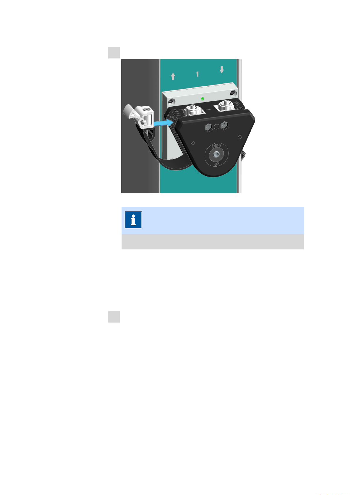
Checking and replacing product parts
2
Mounting the press clamp
■■■■■■■■■■■■■■■■■■■■■■
Figure 57 Mounting the press clamp
NOTICE
Do not fasten or loosen the hex screws of the press clamps.
■ Insert one side of the press clamp with the lug into the groove
provided for this purpose and push it in.
■ Plug the other side in as well with the lug in the groove and push
it in.
■ Make sure that the press clamp is placed so that it is flush and
positioned cleanly.
3
Connecting the tubing with the peristaltic pump
See Connecting the inlet and outlet tubing (see chapter 5.8, page
49).
82
■■■■■■■■
Page 91

■■■■■■■■■■■■■■■■■■■■■■
9 Malfunctions and troubleshooting
9.1 Troubleshooting
Messages or malfunctions in the system are displayed in the control software and on the status display of the respective product component, if
applicable.
■ Messages will be displayed by the control software and describe mal-
functions on the instrument (e.g. jammed drive) or problems with the
control (e.g. missing or invalid parameter). A message informs about
the cause and the solution of a problem.
■ Malfunctions have to be solved directly on the product. If applicable,
this can be done with the help of the control software (e.g. initialization, move to defined position, etc.).
NOTICE
Malfunctions and troubleshooting
Additional information can be found in the context-sensitive software
help or on https://guide.metrohm.com.
■■■■■■■■
83
Page 92

10 Disposal
■■■■■■■■■■■■■■■■■■■■■■
This product is covered by European Directive, WEEE – Waste Electrical
and Electronic Equipment.
The correct disposal of your old product will help to prevent negative
effects on the environment and public health.
More details about the disposal of your old product can be obtained from
your local authorities, from waste disposal companies or from your local
dealer.
84
■■■■■■■■
Page 93

■■■■■■■■■■■■■■■■■■■■■■
Technical specifications
11 Technical specifications
11.1 Ambient conditions
Nominal function range +5 °C - +45 °C at a maximum of 85%
humidity
Storage and transport –20 °C - +70 °C
11.2 Main module – Energy supply
Nominal voltage range
Nominal frequency range 50 Hz - 60 Hz
Power consumption max. 200 W
Protection
Internal fuse 4 ATH cannot be replaced by
100 VAC - 240 VAC
the user
11.3 Pick&Place module – Energy supply
Nominal voltage
Power consumption max. 30 W
Protection
24 VDC internal
Internal fuse 1.5 ATH cannot be replaced by
the user
■■■■■■■■
85
Page 94

Peristaltic pump module – Energy supply
■■■■■■■■■■■■■■■■■■■■■■
11.4 Peristaltic pump module – Energy supply
Nominal voltage 24 VDC internal
Power consumption
Peristaltic pump max. 10 W per pump
Protection
Internal fuse 1.5 ATH cannot be replaced by
the user
11.5 OMNIS sample rack – Energy supply
Nominal voltage
Power consumption max. 0.5 W
5 VDC internal
11.6 OMNIS Sample Robot Pick&Place – Dimensions
The version S of the OMNIS Sample Robot Pick&Place consists of 1 main
module Pick&Place S, 1 Pick&Place module and 1 peristaltic pump module
(2-channel).
Measurements
Width 558 mm
Height 765 mm
Depth 564 mm
Weight
29.3 kg
86
■■■■■■■■
Page 95

■■■■■■■■■■■■■■■■■■■■■■
11.7 Main module Pick&Place – Dimensions
Measurements
Width
Main module S 558 mm
Main module M 1,161 mm
Main module L 1,441 mm
Height
Main module S, M, L
Without workstation 585 mm
Main module S, M, L
With workstation 758 mm
Depth
Technical specifications
Main module S
Without workstation 564 mm
With workstation 604 mm
Main module M, L 564 mm
Weight
Main module S
Without workstation 21.0 kg
Main module M
Without workstation 21.5 kg
Main module L
Without workstation 22.7 kg
■■■■■■■■
87
Page 96

Pick&Place module – Dimensions
11.8 Pick&Place module – Dimensions
Measurements
Width 92 mm
Height 746 mm
Depth 289 mm
Weight
Without magnetic stirrer 4.0 kg
With magnetic stirrer 4.4 kg
11.9 Peristaltic pump module – Dimensions
■■■■■■■■■■■■■■■■■■■■■■
Measurements
Width 92 mm
Height 585 mm
Depth
With 2 pumps 289 mm
With 4 pumps 320 mm
Weight
Without lid tray
With 2 pumps 4.3 kg
With 4 pumps 5.6 kg
With lid tray for working with cov-
With 2 pumps 4.8 kg
With 4 pumps 6.0 kg
With lid tray for working with cov-
ered sample beakers
ered sample beakers
88
Dummy panel 4.0 kg without pumps
■■■■■■■■
Page 97

■■■■■■■■■■■■■■■■■■■■■■
Technical specifications
11.10 OMNIS rack base / OMNIS module base – Dimensions
Measurements
Width 280 mm
Height 115 mm
Depth 564 mm
Weight
OMNIS rack base 3.9 kg
Module base M/L 4.6 kg
11.11 OMNIS sample rack – Dimensions
Measurements
Width 277 mm
Height 125 mm
Depth 277 mm
Weight
Versions
9 x 250 mL 1.5 kg
9 x 200 mL 1.7 kg
16 x 120 mL 1.5 kg
25 x 75 mL 1.8 kg
■■■■■■■■
89
Page 98

Main module Pick&Place – Housing
■■■■■■■■■■■■■■■■■■■■■■
11.12 Main module Pick&Place – Housing
Materials
Lid PBT poly(butylene tereph-
thalate)
Back panel AW-5754 H12 / H22 aluminum, coated
Base AlSi12Cu1 aluminum, coated
Enclosure PBT poly(butylene tereph-
thalate)
PP polypropylene
Front foils PET poly(ethylene tereph-
thalate), mat
IP degree of protection IP 20
11.13 Pick&Place module – Housing
Materials
Lid PBT poly(butylene tereph-
Back panel 1.4301 stainless steel, coated
Base PBT poly(butylene tereph-
Enclosure PP polypropylene
IP degree of protection IP 20
thalate)
thalate)
90
■■■■■■■■
Page 99

■■■■■■■■■■■■■■■■■■■■■■
Technical specifications
11.14 Peristaltic pump module – Housing
Materials
Lid PBT poly(butylene tereph-
thalate)
Back panel AW-5754 H12 / H22 aluminum, coated
Base PBT poly(butylene tereph-
thalate)
Enclosure PP polypropylene
Lid tray AW-5754 H12 / H22 aluminum, coated
IP degree of protection IP 20
11.15 OMNIS Sample Robot Pick&Place – Housing
Materials
Lid AW-5754 H12 / H22 aluminum, coated
Base AlSi12Cu aluminum, coated
IP degree of protection IP 20
11.16 OMNIS module base – Housing
Materials
Lid PBT poly(butylene tereph-
Enclosure PBT poly(butylene tereph-
IP degree of protection IP 40
thalate)
thalate)
■■■■■■■■
91
Page 100

OMNIS sample rack – Housing
■■■■■■■■■■■■■■■■■■■■■■
11.17 OMNIS sample rack – Housing
Materials
Lid PBT poly(butylene tereph-
thalate)
Enclosure PBT poly(butylene tereph-
thalate)
IP degree of protection IP 40
11.18 Main modules – Connectors specifications
Energy supply
Socket IEC 60320, type C14,
Power cord
Length max. 2 m
Number of conductors 3 with protective ground
Conductor cross-section min. 0.75 mm2 / 18 AWG
Plug
Instrument side IEC 60320, type C13,
Building side country-specific
MDL Metrohm Device Link 4 connectors
HID Human Interactive Device
via power connection
10 A
10 A
LAN Local Area Network
Type Ethernet CAT 6
Socket RJ45 shielded
Cable type (min. FFTP) shielded
Cable length max. 10 m from Metrohm accesso-
■■■■■■■■
92
ries
 Loading...