

Page 1
OMNIS Titration Module
Product manual
8.1002.8002EN / 2018-07-27
Page 2

Page 3

Metrohm AG
Ionenstrasse
CH-9100 Herisau
Switzerland
Phone +41 71 353 85 85
Fax +41 71 353 89 01
info@metrohm.com
www.metrohm.com
OMNIS Titration Module
8.1002.8002EN /
2018-07-27
Product manual
Page 4

Technical Communication
Metrohm AG
CH-9100 Herisau
techcom@metrohm.com
This documentation is protected by copyright. All rights reserved.
This documentation has been prepared with great care. However, errors
can never be entirely ruled out. Please send comments regarding possible
errors to the address above.
Page 5

■■■■■■■■■■■■■■■■■■■■■■
Table of contents
1 Overview 1
1.1 OMNIS Titration Module – Product description ................. 1
1.2 OMNIS Titration Module – Product versions ...................... 1
1.3 About the documentation ................................................... 2
1.4 Additional information ......................................................... 3
1.4.1 Accessories .............................................................................. 3
2 Safety 4
2.1 Product safety ....................................................................... 4
2.2 Hazard levels ......................................................................... 4
2.3 Warning symbols .................................................................. 5
2.4 Intended use ......................................................................... 6
Table of contents
2.5 Residual risks ........................................................................ 6
2.5.1 General dangers at the workplace ........................................... 6
2.5.2 Danger from electrical potential ............................................... 7
2.5.3 Danger from biological substances .......................................... 8
2.5.4 Danger from highly flammable substances ............................... 8
2.5.5 Danger from careless transport ................................................ 9
2.5.6 Danger from leakage ............................................................... 9
2.6 Responsibility of the operator ............................................. 9
2.7 Personnel requirement ....................................................... 10
3 Functional description 11
3.1 System overview ................................................................. 11
3.1.1 System – Signals .................................................................... 11
3.1.2 System – Interfaces ................................................................ 12
3.2 OMNIS Titration Module – Overview ................................ 13
3.2.1 Magnetic stirrer – Overview ................................................... 15
3.2.2 Magnetic stirrer with accessories – Overview ......................... 16
3.2.3 Dosing unit – Overview .......................................................... 17
3.2.4 Bottle unit – Overview ........................................................... 21
3.2.5 Measuring Module Analog – Overview .................................. 23
3.2.6 Measuring Module Digital – Overview ................................... 24
3.2.7 OMNIS product with a volumetric KF titration cell – Over-
view ...................................................................................... 25
3.3 OMNIS Titration Module - Function .................................. 26
3.3.1 Magnetic stirrer – Function .................................................... 26
3.3.2 Dosing unit – Function ........................................................... 26
3.3.3 Bottle unit – Function ............................................................ 27
■■■■■■■■
III
Page 6

Table of contents
■■■■■■■■■■■■■■■■■■■■■■
3.3.4 Measuring Module Analog – Functional description ............... 28
3.3.5 Measuring Module Digital – Functional description ................ 29
3.3.6 Karl Fischer titration cell – Function ........................................ 29
3.4 OMNIS Titration Module – Indicators ............................... 29
3.5 Magnetic stirrer – Indicators and controls ....................... 30
3.6 OMNIS Titration Module - Interfaces ............................... 31
3.7 Measuring Module Analog – Interfaces ........................... 32
3.8 Measuring Module Digital – Interfaces ............................ 33
4 Transport and storage 34
4.1 Checking the delivery ......................................................... 34
4.2 Storing the packaging ........................................................ 34
5 Installation 35
5.1 Installation by Metrohm .................................................... 35
5.2 Setting up the product ....................................................... 35
5.3 Mounting the cylinder unit ................................................ 36
5.4 Magnetic stirrer – Installing the accessories .................... 39
5.5 OMNIS system – Mounting the measuring module ......... 41
5.6 Measuring module – Plugging in the electrode cable ..... 43
5.7 OMNIS system – Mounting the electrode ........................ 44
5.8 OMNIS Titration Module – Mounting the volumetric
Karl Fischer titration cell .................................................... 47
5.9 OMNIS titration system – Mounting the bottle unit ....... 59
6 Initial start-up 61
6.1 Initial start-up by Metrohm ............................................... 61
7 Operation and control 62
7.1 Operation ............................................................................ 62
7.2 Refitting the cylinder unit .................................................. 62
7.2.1 Dismantling the cylinder unit ................................................. 62
7.2.2 Mounting the cylinder unit .................................................... 65
7.3 Magnetic stirrer – Operation ............................................. 68
7.3.1 Switching the stirrer on and off .............................................. 68
7.3.2 Setting the stirring rate .......................................................... 69
■■■■■■■■
IV
8 Maintenance 70
8.1 General maintenance ......................................................... 70
8.2 Maintenance agreement .................................................... 71
Page 7

■■■■■■■■■■■■■■■■■■■■■■
9 Malfunctions and troubleshooting 88
10 Disposal 89
11 Technical specifications 90
Table of contents
8.3 Cleaning the product .......................................................... 72
8.3.1 Cleaning the OMNIS Liquid Adapter ...................................... 73
8.3.2 Dosing unit – Maintaining ..................................................... 75
8.3.3 Disassembling the cylinder unit .............................................. 75
8.3.4 Cleaning the cylinder unit ...................................................... 80
8.3.5 Cylinder unit – Cleaning the electrical contacts ....................... 82
8.3.6 Assembling the cylinder unit .................................................. 83
9.1 Troubleshooting .................................................................. 88
11.1 Ambient conditions ............................................................ 90
11.2 OMNIS Titration Module – Energy supply ........................ 90
11.3 OMNIS Magnetic Stirrer – Energy supply ......................... 90
11.4 OMNIS Measuring Module – Energy supply ..................... 90
11.5 OMNIS Titration Module – Dimensions ............................ 90
11.6 OMNIS Magnetic Stirrer – Dimensions ............................. 91
11.7 OMNIS Measuring Module – Dimensions ......................... 91
11.8 OMNIS Titration Module – Housing .................................. 91
11.9 OMNIS Magnetic Stirrer – Housing ................................... 92
11.10 OMNIS Measuring Module – Housing .............................. 92
11.11 OMNIS Titration Module – Connectors specifications .... 93
11.12 OMNIS Measuring Module Digital – Connectors specifi-
cations ................................................................................. 93
11.13 OMNIS Titration Module – Display specifications ........... 93
11.14 OMNIS Measuring Module Digital – Display specifica-
tions ..................................................................................... 94
11.15 OMNIS Measuring Module Analog – Measuring specifi-
cations ................................................................................. 94
11.16 OMNIS Titration Module – Liquid Handling specifica-
tions ..................................................................................... 95
11.17 Magnetic stirrer – Stirrer specifications ............................ 96
■■■■■■■■
V
Page 8

Page 9
■■■■■■■■■■■■■■■■■■■■■■
1 Overview
1.1 OMNIS Titration Module – Product description
The OMNIS Titration Module is a titration module that is controlled by an
OMNIS Titrator. The OMNIS Titration Module is equipped with the following functional units:
■ Two plug-in positions at which a maximum of two measuring modules
can be fitted.
■ One dosing unit with interchangeable cylinder units.
■ One integrated magnetic stirrer, depending on the product version.
1.2 OMNIS Titration Module – Product versions
The product is available in the following versions:
Overview
Table 1
Art. no. Designation Version feature
2.1002.0010 OMNIS Titration Module Without magnetic stirrer
2.1002.0110 OMNIS Titration Module With integrated magnetic
Product versions
stirrer
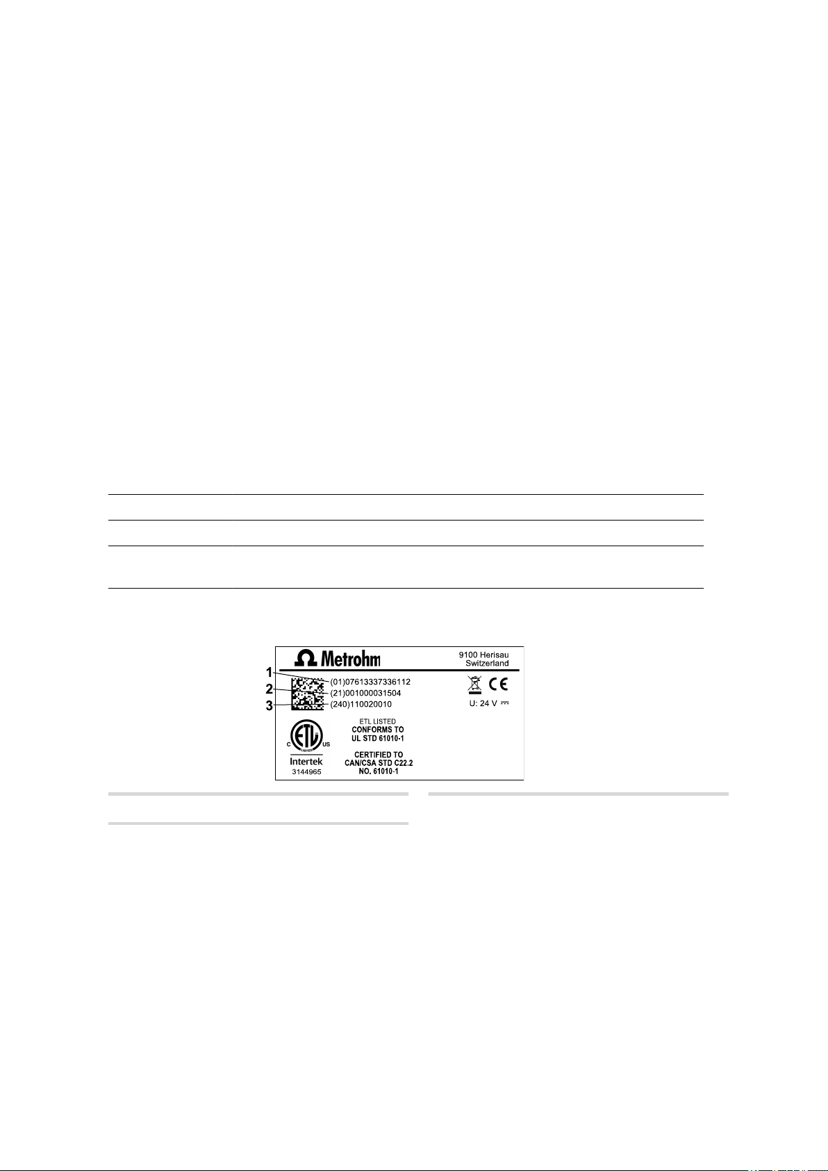
The required numbers for the customer service can be found on the type
plate (see example):
(01) = External article number
1
(240) = Metrohm article number
3
(21) = Serial number
2
■■■■■■■■
1
Page 10
About the documentation
NOTE
Information on the accessories for the respective product version can
be obtained either on the Internet at http://www.metrohm.com or
via your regional Metrohm representative.
1.3 About the documentation
NOTE
Please read through this documentation carefully before putting the
product into operation.
The documentation contains important information and warnings
which you must follow in order to ensure safe operation of the product.
■■■■■■■■■■■■■■■■■■■■■■
Symbols and conventions
The following icons and formatting may appear in this documentation:
Cross-reference to figure legend
The first number refers to the figure number, the second to the product part in the figure.
Instruction step
Carry out these steps in the sequence shown.
Method Designations for names of parameters, menu items,
tabs and dialog windows in the software.
File ▶ New Menu or menu item
Work area /
Properties
[Next] Button or key
Menu paths in order to arrive at a particular position
in the software.
■■■■■■■■
2
Page 11

■■■■■■■■■■■■■■■■■■■■■■
1.4 Additional information
Additional information concerning the topic can be found:
■ in the Software Help
■ in the Metrohm information portal on the Internet https://
guide.metrohm.com
1.4.1 Accessories
Up-to-date information on the scope of delivery and optional accessories
for your product can be found on the Internet. You can download this
information using the article number as follows:
Downloading the accessories list
Enter https://www.metrohm.com/ into your Internet browser.
1
Enter the article number of the product (e.g. 2.1001.0010) into the
2
search field.
Overview
The search result is displayed.
Click on the product.
3
Detailed information regarding the product is shown on various tabs.
On the Included parts tab, click Download the PDF.
4
The PDF file with the accessories data is created.
NOTE
When you receive your new product, we recommend downloading
the accessories list from the Internet, printing it out and keeping it for
reference purposes.
■■■■■■■■
3
Page 12
Product safety
2 Safety
2.1 Product safety
This product exhibited no flaws in terms of technical safety at the time it
left the factory. To preserve this status and ensure non-hazardous operation of the product, the following instructions must be observed carefully.
2.2 Hazard levels
The following warning messages indicate the severity of the danger and
its possible effects.
■■■■■■■■■■■■■■■■■■■■■■
DANGER
Immediate danger of life
Irreversible injuries that will result in death.
Warns of dangerous situations or unsafe actions that will most certainly cause severe injuries or death.
Lists measures to avoid hazard.
WARNING
Severe health hazards
Serious injuries that could result in death.
Warns of dangerous situations or unsafe actions that could result in
serious injuries or death.
Lists measures to avoid hazard.
■■■■■■■■
4
Page 13

■■■■■■■■■■■■■■■■■■■■■■
CAUTION
Health hazards or severe property damage
Warns of dangerous situations or unsafe actions that could result in
moderate injuries or considerable property damage.
Lists measures to avoid hazard.
2.3 Warning symbols
Make sure that any additional hazard symbols are marked on the product
for your operation of the product.
The following warning symbols in the documentation and at hazard areas
of the product point out hazard potentials:
– Warning of a hazard area
Safety
NOTE
Warning symbol on the product
If this warning symbol is on the product, read the respective documentation prior to installation and initial start-up.
– Warning of electric shock from electrical potential
– Warning of danger of fire and explosion from highly flammable
substances and gases
– Warning of danger of poisoning and chemical burns from chemi-
cal hazardous substances
– Warning of danger of infection and poisoning from biological
hazardous substances
– Warning of risk of injury from high temperatures
■■■■■■■■
5
Page 14

Intended use
– Warning of cut injuries from pieces of broken glass and/or sharp
edges
– Warning of risk of injury by laser radiation
– Warning of dangerous optical radiation
2.4 Intended use
Metrohm products are used for the analysis and handling of chemicals.
Usage therefore requires the user to have basic knowledge and experience
in handling chemicals. Knowledge regarding the application of fire prevention measures prescribed for laboratories is also mandatory.
Adherence to this technical documentation and compliance with the
maintenance specifications make up an important part of intended use.
■■■■■■■■■■■■■■■■■■■■■■
Any utilization in excess of or deviating from the intended use is regarded
as misuse.
Specifications regarding the operating values and limit values of individual
products are contained in the "Technical specifications" section, if relevant.
Exceeding and/or not observing the mentioned limit values during operation puts people and components at risk. The manufacturer assumes no
liability for damage due to non-observance of these limit values.
The EU declaration of conformity loses its validity if modifications are carried out on the products and/or the components.
2.5 Residual risks
2.5.1 General dangers at the workplace
Generally, the regulations and provisions of the regulatory institutions and
authorities in the field of work apply.
The instructions regarding the following areas have to be followed when
using the products:
■ Work safety
■ Handling mechanical installations
■ Handling electricity
■ Handling hazardous and environmentally damaging substances
■ Handling hazardous and environmentally damaging liquids
■ Disposing hazardous and environmentally damaging substances
■■■■■■■■
6
If they are not followed, this may result in:
Page 15

■■■■■■■■■■■■■■■■■■■■■■
Safety
■ Disturbing, injuring and/or killing of people
■ Malfunction and/or damage to instruments and infrastructure
■ Damage and/or contamination of the environment
WARNING
General dangers at workplace
If the safety measures are not followed, working in a laboratory bears
a high risk of injury, which can endanger your life and health.
■ Only professionally trained and qualified specialist personnel may
operate the products.
■ Follow the applicable provisions concerning work safety and all
regulations on wearing protective clothing.
■ Use suitable tools to perform your work.
■ Check the fill level of waste bottles or waste canisters and analysis
vessels, and make sure they do not overflow.
■ Use protective grounding when working with highly flammable
substances and gases.
2.5.2 Danger from electrical potential
WARNING
Electric shock from electrical potential
Risk of injury by touching live components or through moisture on
live parts.
■ Never open the housing of the instrument.
■ Protect live parts (e.g. power supply unit, power cord, connection
sockets) against moisture.
■ If you suspect that moisture has gotten into the instrument, dis-
connect the instrument from the energy supply. Then notify Metrohm Service.
■ Only personnel who have been issued Metrohm qualification may
perform service and repair work on electrical and electronic components.
■■■■■■■■
7
Page 16

Residual risks
2.5.3 Danger from biological substances
If the product is used for biological hazardous substances, it must be
marked in accordance with regulations.
In case of a return shipment to Metrohm or a Metrohm Service partner,
the product or product component has to be decontaminated and the
hazard symbol for biological hazardous substances must be removed. A
declaration of decontamination must be enclosed.
WARNING
Danger of infection and poisoning from biological hazardous
substances
Poisoning from toxins and/or infections from samples contaminated
with microorganisms.
■ Clean and disinfect contaminated surfaces.
■ Wear protective equipment.
■ Use exhaust equipment when working with vaporizing hazardous
substances.
■ Dispose of biologically contaminated substances properly.
■■■■■■■■■■■■■■■■■■■■■■
2.5.4 Danger from highly flammable substances
WARNING
Danger of fire and explosion from highly flammable substances
and gases
Burns from fire and/or injuries from explosions.
■ Avoid ignition sources.
■ Use protective grounding.
■ Use exhaust equipment.
■■■■■■■■
8
Page 17

■■■■■■■■■■■■■■■■■■■■■■
2.5.5 Danger from careless transport
WARNING
Risk of injury from careless transport
Injuries from spilled chemical and/or biological substances, falling
parts and pieces of broken glass.
■ Remove loose parts (e.g. sample racks, sample beaker, bottles)
before transport.
■ Remove liquids.
■ Lift and transport the instrument with both hands on the base
plate.
■ Lift and transport heavy instruments only according to instruc-
tions.
2.5.6 Danger from leakage
Safety
WARNING
Risk of injury by leakage
A risk of injury exists in connection with escaping liquids of leaking
parts and/or connection elements.
■ Replace leaking parts and connection elements without delay.
■ Tighten loose connecting elements.
■ Use environmentally-friendly methods to dispose of escaping liq-
uids.
2.6 Responsibility of the operator
■ Eliminate defects or damage which impair operating safety without
delay.
■ Eliminate malfunctions which could impair safety without delay.
■ The rules, regulations and instructions listed in the present document
are not the only valid ones. Comply with the applicable statutory rules,
government agency directives and regulations.
■ Unauthorized modification of the products excludes any and all liability
on the part of the manufacturer for any damage resulting from this as
well as for any consequential damage. No modifications, attachments
or conversions which could impair safety may be carried out on the
products without the approval of the manufacturer.
■■■■■■■■
9
Page 18

Personnel requirement
■ Spare parts must meet the technical requirements established by the
manufacturer. Original spare parts always meet these requirements.
■ Personnel must be familiar with this safety-relevant information and it
must be available for consultation at all times.
2.7 Personnel requirement
Only qualified personnel may operate the present product.
Qualified personnel are people authorized by the safety responsible to
carry out the necessary operations. They are capable of recognizing and
avoiding possible dangers. These people are qualified due to their professional training, experience and/or instruction. They know the relevant
standards, laws, provisions, accident prevention regulations and the company conditions.
■■■■■■■■■■■■■■■■■■■■■■
10
■■■■■■■■
Page 19

■■■■■■■■■■■■■■■■■■■■■■
3 Functional description
3.1 System overview
3.1.1 System – Signals
Visual signals
All products and components of the system that are equipped with multicolor status displays indicate their respective status using colors and flashing patterns.
The meaning of the colors and flashing patterns is explained in the following table.
NOTE
Functional description
Use of the flashing patterns
Not all products and components use all of the flashing patterns illustrated below.
However, the meaning of the flashing patterns is the same for all
products and components.
Signal Meaning
LED lights up yellow System start or initialization
LED flashes yellow (slowly) Ready for connection setup or
locking
LED flashes yellow (fast) Connection setup started or
locking underway
LED lights up green Ready for operation
LED flashes green (slowly) In operation
LED flashes red (fast) Malfunction or error
■■■■■■■■
11
Page 20

System overview
3.1.2 System – Interfaces
The system provides the following interfaces:
■■■■■■■■■■■■■■■■■■■■■■
Designation Abbrevia-
Symbol Use
tion
Metrohm Device Link MDL For connecting additional mod-
ules or products to a basic product.
Human Interactive Device HID For connecting an external con-
trol product.
Metrohm Solution Identification MSI For connecting the OMNIS Liq-
uid Adapter.
Local Area Network LAN For connecting the product to a
local network.
USB connector USB For connecting USB devices.
12
■■■■■■■■
Page 21
■■■■■■■■■■■■■■■■■■■■■■
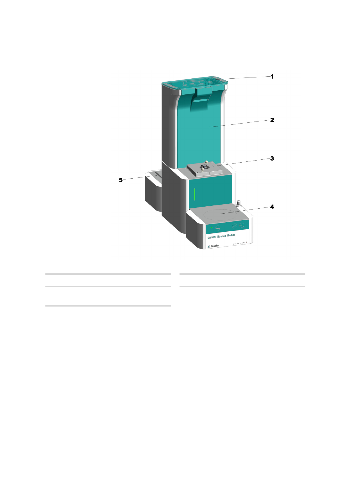
3.2 OMNIS Titration Module – Overview
Functional description
Lid
1
Dosing drive
3
Platform
5
For chemical bottle.
Figure 1 OMNIS Titration Module – Front
Space for measuring modules
2
Magnetic stirrer
4
Optional, can be retrofitted.
■■■■■■■■
13
Page 22

OMNIS Titration Module – Overview
■■■■■■■■■■■■■■■■■■■■■■
Figure 2 OMNIS Titration Module – Rear
Bottle holder
1
MSI connector
3
MSI = Metrohm Solution Identification. Connection socket for Liquid Adapter cable.
Cable guide
5
Bottom right.
Cable guide
7
On the side to the left. For rod stirrer cable
or electrode cable.
Cable guide
2
On the side to the right. For Liquid Adapter
cable.
MDL connector
4
MDL = Metrohm Device Link. Connection
socket for the connecting cable to the basic
unit.
Cable guide
6
Bottom left.
14
■■■■■■■■
Page 23
■■■■■■■■■■■■■■■■■■■■■■
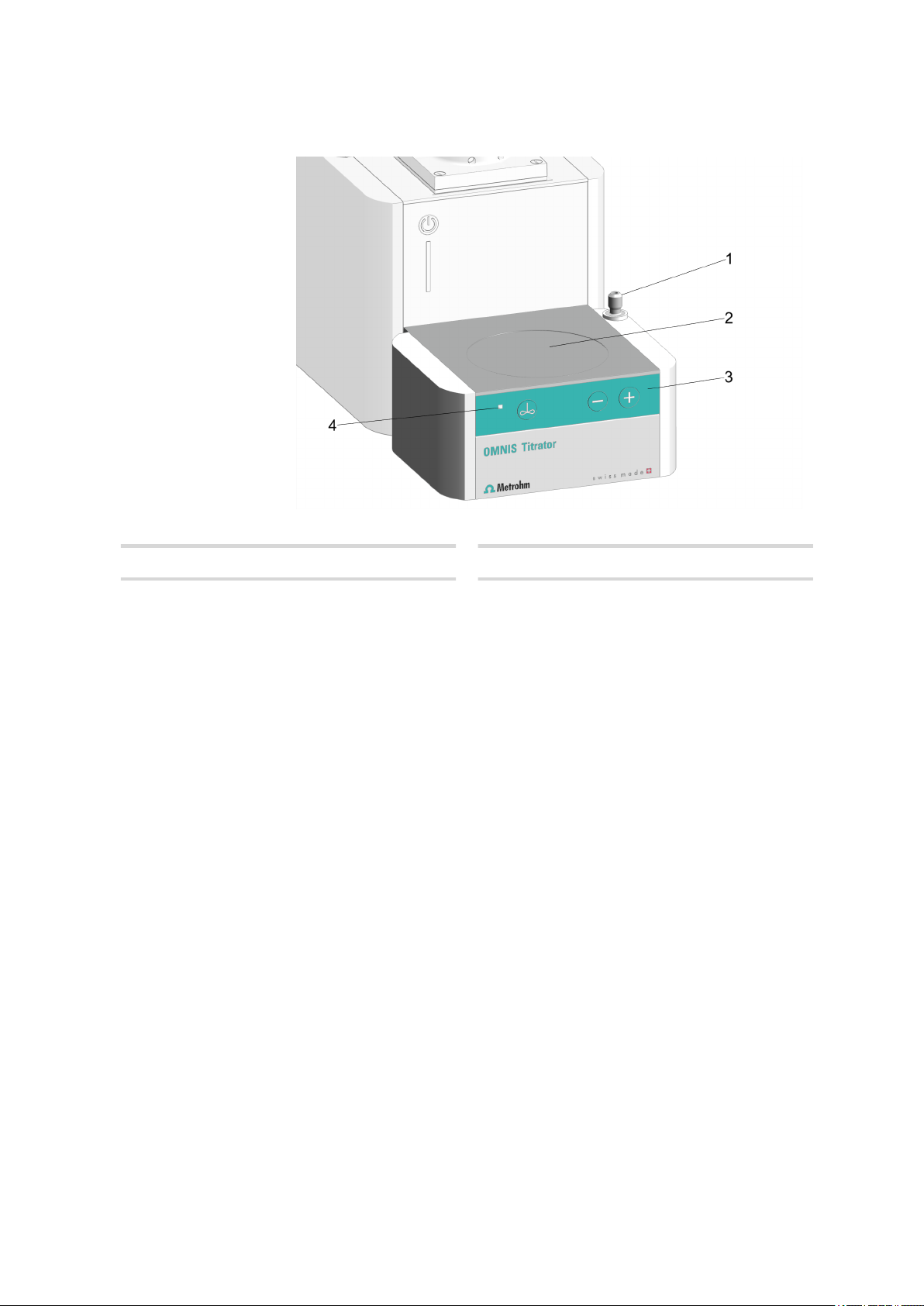
3.2.1 Magnetic stirrer – Overview
Functional description
Stand attachment
1
Control bar
3
Figure 3 Magnetic stirrer – Overview
Stirring area
2
Status display
4
LED. Multi-colored
■■■■■■■■
15
Page 24
OMNIS Titration Module – Overview
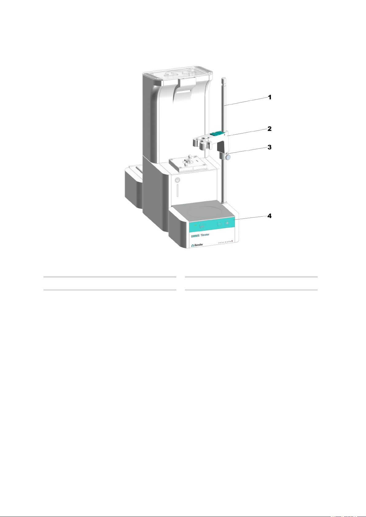
3.2.2 Magnetic stirrer with accessories – Overview
■■■■■■■■■■■■■■■■■■■■■■
Support rod
1
Clamping ring
3
Figure 4 Magnetic stirrer with accessories – Overview
Electrode holder
2
Control bar
4
16
■■■■■■■■
Page 25

■■■■■■■■■■■■■■■■■■■■■■
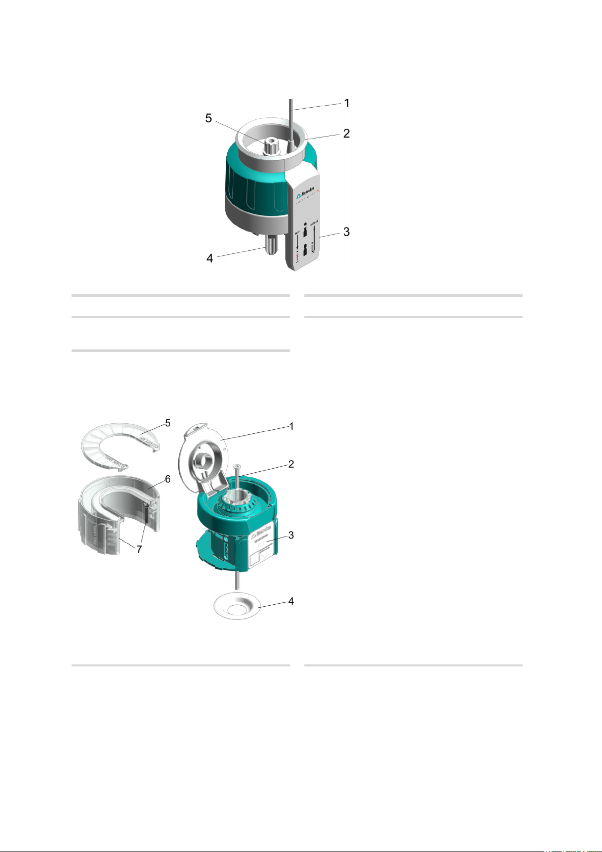
3.2.3 Dosing unit – Overview
Functional description
Distributor
1
With four ports
Dosing drive
3
Installed
Figure 5 Dosing unit – Overview
Cylinder unit
2
Available with various volumes
■■■■■■■■
17
Page 26

OMNIS Titration Module – Overview
Figure 6 Dosing drive - Overview
■■■■■■■■■■■■■■■■■■■■■■
Status display
1
LED. Multi-colored
Twistlocks
3
For locking the cylinder unit
Contact pins
2
For communicating with the cylinder unit
Piston rod
4
For moving the piston
18
■■■■■■■■
Page 27

■■■■■■■■■■■■■■■■■■■■■■
2
3
5
6
7
1
4
8
3.2.3.1 Cylinder unit – Overview
Functional description
Distributor
1
With four ports for solutions
Housing
3
Centering tube
5
Piston
7
Figure 7 Cylinder unit – Overview
Cylinder top piece
2
Unlocking button
4
Cylinder
6
8
Data chip
■■■■■■■■
19
Page 28

OMNIS Titration Module – Overview
Figure 8 Cylinder unit – Overview from above
The four ports of the cylinder unit are intended for the following uses:
■■■■■■■■■■■■■■■■■■■■■■
Table 2
Port Use Connecting or sealing with
1 Dosing Dosing tip
2 Filling the cylinder Chemical bottle
3 Not used Stopper
4 Not used Stopper
Use of the ports
The intended use of the ports can be changed in the OMNIS Software.
20
■■■■■■■■
Page 29
■■■■■■■■■■■■■■■■■■■■■■
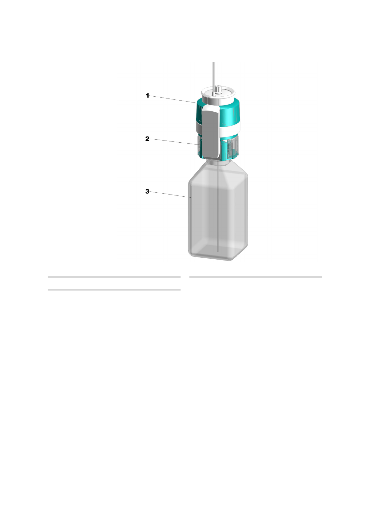
3.2.4 Bottle unit – Overview
Functional description
OMNIS Liquid Adapter
1
Chemical bottle
3
Figure 9 Bottle unit
Bottle cap multi-use
2
■■■■■■■■
21
Page 30
OMNIS Titration Module – Overview
3.2.4.1 OMNIS Liquid Adapter – Overview
Figure 10 OMNIS Liquid Adapter – Parts
■■■■■■■■■■■■■■■■■■■■■■
Cable
1
RFID reader
3
Tubing adapter
5
Part of 6.01600.xxx
3.2.4.2 Bottle cap multi-use – Overview
Status display
2
Aspiration tube
4
Part of 6.01600.xxx
Figure 11 Bottle cap multi-use, complete (6.01601.000)
Flip-top lid
1
■■■■■■■■
22
Aspiration tubing
2
Aspiration tubing (6.1819.020)
Page 31

■■■■■■■■■■■■■■■■■■■■■■
Functional description
RFID tag
3
RFID label for contact-free data transmission.
5 - 7 Absorption cartridge, complete
Absorption cartridge, complete
(6.02701.000)
Absorption cartridge housing
6
PTFE sealing ring
4
PTFE sealing ring (6.02701.010)
Absorption cartridge lid
5
Absorption cartridge insert
7
(2 pieces)
3.2.5 Measuring Module Analog – Overview
Figure 12
INPUT 1
1
Connection socket for potentiometric sensors (green coding), temperature sensors
(red coding) and polarizable sensors (blue
coding)
REF
3
Connection socket for reference electrodes
Measuring Module Analog – Overview
INPUT 2
2
Connection socket for potentiometric sensors (green coding) and temperature sensors
(red coding)
Fastening screws
4
Fastening screws, left and right. These fasten
the measuring module in the housing and
ground the electronics.
■■■■■■■■
23
Page 32

OMNIS Titration Module – Overview
3.2.6 Measuring Module Digital – Overview
■■■■■■■■■■■■■■■■■■■■■■
Figure 13 Measuring Module Digital – Overview
Fastening screws
1
Fastening screws, left and right. These fasten
the measuring module in the housing and
ground the electronics.
Connection socket
2
For dTrodes
24
■■■■■■■■
Page 33

■■■■■■■■■■■■■■■■■■■■■■
Functional description
3.2.7 OMNIS product with a volumetric KF titration cell – Overview
Support rod
1
KF titration vessel lid
3
Titration vessel
5
Figure 14 OMNIS product with an installed volumetric KF titration cell
Locking lever
2
Clamping ring
4
Control bar for stirrer
6
■■■■■■■■
25
Page 34

OMNIS Titration Module - Function
3.3 OMNIS Titration Module - Function
The OMNIS Titration Module is a module for carrying out titrations. It only
works together with an instrument that has an electrical and a network
connection.
The OMNIS Titration Module is equipped with the following functional
units:
■ Slots for a maximum of two measuring modules.
The Measuring Module Digital is used for connecting digital electrodes,
the so-called dTrodes.
The Measuring Module Analog is used for connecting analog electrodes.
■ Dosing unit with an interchangeable cylinder unit.
■ One magnetic stirrer, depending on the product version.
■ Bottle unit with reagent detection.
■ Cable guides
Cable guides are located at the rear and on the base of the OMNIS
Titration Module. The OMNIS Liquid Adapter cable can be guided to
the connection socket in the cable guide on the right-hand side. The
cable of a rod stirrer can be guided in the lateral and bottom cable
guides on the left-hand side to the connection socket at the rear of the
instrument.
■■■■■■■■■■■■■■■■■■■■■■
3.3.1 Magnetic stirrer – Function
The magnetic stirrer ensures that the sample is very well mixed. An electrode holder with clamping ring can be fastened to its support rod. The
electrode, the buret tip and a rod stirrer can be inserted into the electrode
holder. Depending on the application, the support rod can also be used
for mounting the KF titration cell.
3.3.2 Dosing unit – Function
Software controls can be used for accurate dosing of liquid volumes with
the dosing unit.
The dosing unit is comprised of the following units:
■ The dosing drive
■ The cylinder unit
The dosing drive is permanently installed in the housing of the instrument.
It is controlled via the OMNIS Software and is responsible for the accurate
dosing of the solution.
If the cylinder unit is placed on top of the dosing drive, the dosing drive
assumes responsibility for the following functions:
26
■■■■■■■■
Page 35

■■■■■■■■■■■■■■■■■■■■■■
Functional description
■ Raising and lowering the piston:
Solution is aspirated if the piston is lowered. The cylinder fills up.
Solution is dosed if the piston is raised. The cylinder empties.
■ Rotating the cylinder:
The rotation of the cylinder controls which of the four ports the solution flows through.
The valve disk with an opening is located in the middle of the cylinder
base.
The distributor disk with four openings corresponding to the four ports
of the distributor is located at the bottom in the cylinder attachment.
The dosing drive rotates the cylinder by 90° stages so that the opening
of the valve disk fits with an opening on the distributor disk. This
results in a passage for the solution to the corresponding port of the
distributor.
3.3.2.1
Cylinder unit – Function
The cylinder unit is an accessory set for the dosing unit in OMNIS instruments with dosing function.
The movements of the piston and the cylinder are controlled via the
OMNIS Software.
An antidiffusion tip (6.1543.200) is part of the accessories of every cylinder unit. The antidiffusion tip is used whenever the titration tip is
immersed into the sample. The antidiffusion valve prevents the sample
from diffusing into the tip.
If accurate dosing is important, then you can order a dosing tip
(6.1543.100) as an alternative to the antidiffusion tip. The dosing tip must
not immerse into the sample.
See also
Cylinder unit – Overview (Chapter 3.2.3.1, page 19)
3.3.3 Bottle unit – Function
The bottle unit contains the chemicals that are required for the analysis.
The bottle unit in an OMNIS system is comprised of the following elements:
■ Chemical bottle
■■■■■■■■
27
Page 36

OMNIS Titration Module - Function
■■■■■■■■■■■■■■■■■■■■■■
■ OMNIS bottle cap
The OMNIS bottle cap fits on a chemical bottle with GL 45 thread. Suitable adapters are available for chemical bottles with other threads.
The green bottle cap multi-use is equipped with a writeable RFID tag.
The RFID tag can be inscribed with information regarding the solution.
The red bottle cap single-use is equipped with an RFID tag. The RFID
tag contains manufacturer's information regarding the composition
and concentration of the solution.
■ OMNIS Liquid Adapter
The OMNIS Liquid Adapter has an RFID tag reader that transfers the
data between the RFID tag of the bottle cap and the OMNIS Software.
See also
OMNIS Liquid Adapter – Functions (Chapter 3.3.3.1, page 28)
3.3.3.1
OMNIS Liquid Adapter – Functions
The basic principle
There is no fixed connection between the OMNIS Liquid Adapter and the
chemical bottle that must be loosened when changing bottles. This means
that you can transfer the OMNIS Liquid Adapter without difficulty from
one bottle to another.
Liquid transfer
The liquid transfer is the responsibility of an aspiration tube installed in the
OMNIS Liquid Adapter. When you place the OMNIS Liquid Adapter on the
bottle, the aspiration tube presses on the aspiration tubing in the chemical
bottle. A tightly sealed connection is made.
Contact-free data transmission
Information regarding the content of the chemical bottle is stored on an
RFID tag on the bottle cap. The OMNIS Liquid Adapter has an RFID tag
reader that reads this data.
The data cable fastened to the OMNIS Liquid Adapter transfers the information to the analyzer and to the software.
3.3.4 Measuring Module Analog – Functional description
The Measuring Module Analog is used as an interface for analog electrodes on an OMNIS Titrator or an OMNIS Titration Module.
The Measuring Module Analog contains the electronics necessary for the
use of analog sensors. Analog electrodes and analog reference electrodes
can be plugged into its connection sockets.
■■■■■■■■
28
Page 37

■■■■■■■■■■■■■■■■■■■■■■
3.3.5 Measuring Module Digital – Functional description
The Measuring Module Digital is used as an interface for digital electrodes
on an OMNIS Titrator or an OMNIS Titration Module.
The digital electrodes, the dTrodes, can be plugged into its connection
socket.
3.3.6 Karl Fischer titration cell – Function
The Karl Fischer titration cell is a closed vessel for water content determination according to Karl Fischer which is fastened to the support rod of
the magnetic stirrer.
The Karl Fischer titration cell consists of a titration vessel (different variants
exist) and a titration vessel lid (different variants with or without homogenizer (Polytron PT 1300 D) exist).
Seepage of moisture into the titration cell is prevented with seals and with
the adsorber tube, which is filled with molecular sieve.
Functional description
3.4 OMNIS Titration Module – Indicators
Status display
1
Multi-colored
Figure 15
OMNIS Titration Module – Indicators
The status of the instrument is displayed with the status display (15-1)
using different colors (see Chapter 3.1.1, page 11).
See also
■■■■■■■■
29
Page 38

Magnetic stirrer – Indicators and controls
■■■■■■■■■■■■■■■■■■■■■■
System – Signals (Chapter 3.1.1, page 11)
3.5 Magnetic stirrer – Indicators and controls
Figure 16 Magnetic stirrer – Control bar
Status display
1
Multi-colored
Key for reducing the stirring rate
3
Reduce the stirring rate by one step.
Indicators
The status of the instrument is displayed with the status display Required
link is broken! Target id: NOTFOUND_ID_7d935f2a63deaf5e0a9dd569502aec03-61e151306000d4a00
a9dd569530521bd-en-US(see Chapter 3.1.1, page 11).
Controls
The keys (16-2), (16-3) and (16-4) are used for the hardware-side operation of the magnetic stirrer.
The most recently used stirring rate will be used again when the
instrument is switched on.
NOTE
Stirrer on/off key
2
Switch the stirrer on and off.
Key for increasing the stirring rate
4
Increase the stirring rate by one step.
30
The current stirring rate is displayed in the software under Manual control.
■■■■■■■■
Page 39

■■■■■■■■■■■■■■■■■■■■■■
NOTE
The stirrer can also be controlled via the software.
Other functions in the software
The following functions can be executed only with the OMNIS Software:
■ Setting the stirring direction.
■ Deactivating keys.
The magnetic stirrer can be operated only via the software.
■ Switching over the keys for the rod stirrer.
The keys on the magnetic stirrer operate the rod stirrer.
3.6 OMNIS Titration Module - Interfaces
Functional description
Figure 17
MSI connector
1
MSI = Metrohm Solution Identification. Connection socket for Liquid Adapter cable.
OMNIS Titration Module - Interfaces
MDL connectors
2
MDL = Metrohm Device Link. Connection
socket for connecting cable between OMNIS
instruments.
■■■■■■■■
31
Page 40

Measuring Module Analog – Interfaces
■■■■■■■■■■■■■■■■■■■■■■
3.7 Measuring Module Analog – Interfaces
The Measuring Module Analog has 3 connection sockets for analog electrodes.
Connection socket INPUT 1
1
Connection socket REF
3
Figure 18 Measuring Module Analog – Interfaces and connectors
Connection socket INPUT 2
2
Connection socket INPUT 1 and INPUT 2
The connection sockets INPUT 1 and INPUT 2 are marked with colored
circle segments.
The markings are indicating that only a certain type of electrode cable may
be plugged into this connection socket:
Meaning of the colors:
red
The connector supports temperature sensors
blue The connector supports polarized sensors
green The connector supports potentiometric sensors
Connection socket REF
Reference electrodes can be plugged into the REF connection socket.
32
■■■■■■■■
Page 41

■■■■■■■■■■■■■■■■■■■■■■
3.8 Measuring Module Digital – Interfaces
The Measuring Module Digital has 1 connection socket for a digital electrode.
Functional description
Figure 19 Measuring Module Digital – Interfaces and connectors
Connection socket for digital electro-
1
des
Connection socket
The black marking around the connection socket indicates that only a
cable of a digital electrode may be plugged in here.
■■■■■■■■
33
Page 42

Checking the delivery
4 Transport and storage
4.1 Checking the delivery
Immediately upon arrival of the merchandise, check the shipment against
the delivery note to ensure completeness and absence of damage.
4.2 Storing the packaging
The product is supplied in extremely protective packaging together with
the separately packed accessories. Keep this packaging, as only this
ensures safe transportation of the product.
■■■■■■■■■■■■■■■■■■■■■■
34
■■■■■■■■
Page 43

■■■■■■■■■■■■■■■■■■■■■■
5 Installation
5.1 Installation by Metrohm
NOTE
Installation of the products
As a basic rule, the installation of the system and of the new products
and modules is handled by trained and instructed specialists from the
Metrohm Company and/or its representative.
5.2 Setting up the product
Installation
The product has been developed for operation indoors and may not be
used in explosive environments.
Place the product in a location of the laboratory which is suitable for operation and free of vibrations and which provides protection against corrosive atmosphere and contamination by chemicals.
Observe the dimensions and weights of the individual products and modules that are part of the complete system. You will find this information in
the "Technical specifications" section.
Protect the product against excessive temperature fluctuations and direct
sunlight.
The power cord and other connecting cables must not be replaced with
impermissible cables.
The power cord, where available, or other cables connecting to control
instruments must be accessible during operation.
■■■■■■■■
35
Page 44

Mounting the cylinder unit
5.3 Mounting the cylinder unit
NOTE
Default settings in the OMNIS Software
Port 1 is defined as dosing port and Port 2 as fill port in the OMNIS
Software default settings. The following instructions describe the
default setting.
If required, the ports can also be used differently. If the ports are used
differently from the default settings, the changes have to be entered
into the OMNIS Software in Properties ▶ Specific data of the dosing unit.
NOTE
■■■■■■■■■■■■■■■■■■■■■■
Before you mount the cylinder unit, the dosing unit has to be moved
into the exchange position.
The function for moving the dosing unit into the exchange position
can be found in the OMNIS Software in Manual control.
Preparing the mounting
1
2
Mounting the cylinder unit
These instructions describe the default installation as defined in the
OMNIS Software.
Start the Manual control of the dosing unit in the OMNIS Software.
Start the Exchange position function.
Observe the splash warning and carry out the function.
NOTE
36
Prerequisite
The dosing unit is in the exchange position.
■■■■■■■■
Page 45

■■■■■■■■■■■■■■■■■■■■■■
Installation
Accessories
■ Wrench (6.2739.000)
Attaching the cylinder unit
■ Rotate the cylinder unit until the marking
with the label UNLOCK is in line with the
marking on the dosing drive.
■ Set the cylinder unit down onto the two
twistlocks straight from above.
Locking the cylinder unit
■ Rotate the cylinder unit to the left until it
stops.
The marking with the label LOCK is an indicator.
■■■■■■■■
37
Page 46

Mounting the cylinder unit
■■■■■■■■■■■■■■■■■■■■■■
Mounting the stoppers
■ Screw a stopper (6.1446.010) in each of the
two ports 3 and 4.
■ Firmly tighten the stoppers with the wrench
(6.2739.000).
Mounting the tubings
■ Tighten an FEP tubing (6.1805.100) into
port 1.
This tubing works as a dosing tubing.
Tighten the other end to the dosing tip.
■ Tighten the second FEP tubing (6.1805.100)
into port 2.
This tubing works as a filling tubing. Tighten
the other end to the OMNIS Liquid Adapter.
■ Firmly tighten the screws with the wrench
(6.2739.000).
38
■■■■■■■■
Page 47

■■■■■■■■■■■■■■■■■■■■■■
5.4 Magnetic stirrer – Installing the accessories
Mounting the electrode holder
Accessories
■ Support rod, 30 cm (6.2016.050)
■ Clamping ring, 10 mm (6.2013.010)
■ Electrode holder (6.02005.000)
Mounting the support rod
Screw the support rod onto the stand attachment .
Installation
Mounting the clamping ring
Push the clamping ring over the support rod
with the indent facing upward.
■■■■■■■■
39
Page 48

Magnetic stirrer – Installing the accessories
■■■■■■■■■■■■■■■■■■■■■■
Mounting the electrode holder
1. Press the green locking lever on the electrode holder.
2. Push the electrode holder over the support
rod.
3. To fix in place, release the green locking
lever at the desired height.
The electrode holder is fixed in place.
NOTE
The clamping ring is used as the lower stop
for the electrode holder. The clamping ring
prevents the electrode holder with the
mounted electrode from being lowered too
far.
1. Push the clamping ring under the electrode holder.
2. Rotate the clamping ring in such a way
that the wedge on the electrode holder
fits in the indent in the clamping ring.
3. Fix the clamping ring with the knurled
screw in place at the desired height.
40
■■■■■■■■
Page 49

■■■■■■■■■■■■■■■■■■■■■■
Preparing the magnetic stirrer for operation
Placing beaker and stirring bar
Installation
1. Place a 16 mm (6.1903.020) or 25 mm
(6.1903.030) PTFE stirring bar in the sample beaker.
2. Place the sample beaker on the contact
surface of the magnetic stirrer.
5.5 OMNIS system – Mounting the measuring module
Two measuring modules each can be installed in every OMNIS Titrator and
in every OMNIS Titration Module.
Each measuring module must be screwed tightly into the instrument to
ensure trouble-free operation. Proceed as follows:
Opening the lid
Open the lid of the titrator.
■■■■■■■■
41
Page 50

OMNIS system – Mounting the measuring module
■■■■■■■■■■■■■■■■■■■■■■
Removing the side parts
Carry out the following steps on both sides of
the instrument.
1. Remove the two screws from above using
the hex key.
2. Push the side covering upwards until it can
be removed from the side.
3. Remove the side covering to the side.
Removing the fastening screws
The measuring module is supplied with
screwed in fastening screws.
■ Remove the two fastening screws from the
measuring module using the hex key.
Inserting the measuring module
Insert the measuring module into an empty
slot. The slots are designated with 1 (rear) and
2 (front).
42
■■■■■■■■
Page 51

■■■■■■■■■■■■■■■■■■■■■■
Installation
Attaching the measuring module
Insert the fastening screws. Tighten the measuring module to the housing from both sides
using the hex key.
Mounting the side parts
Carry out the following steps on both sides of
the instrument.
1. Position the side covering from the side in
an elevated position.
2. Insert the side covering into the guide rail
and push it downwards.
3. Insert the two screws and tighten them
from above using the hex key.
5.6 Measuring module – Plugging in the electrode cable
Plugging the electrode cable into the
measuring module
1. Align the red dot on the plug with the
groove on the connection socket of the
measuring input.
2. Plug in the cable until you can feel it snap
in.
■■■■■■■■
43
Page 52

OMNIS system – Mounting the electrode
■■■■■■■■■■■■■■■■■■■■■■
NOTE
It should be easy to plug in the cable.
■ Do not apply force if the plug cannot be
inserted easily!
■ Rotate the plug to the right or left using
light pressure until it latches in the
socket.
Guiding out the cable
1. Guide the cable out going under the bar.
2. Close the lid.
5.7 OMNIS system – Mounting the electrode
CAUTION
Risk of cuts from sharp edges
Cut injuries from pieces of broken glass and/or sharp edges.
■ Handle glass parts (e.g. electrode, sample beaker) with care.
■ Only use undamaged glass parts.
■ Dispose of damaged glass parts immediately.
44
■■■■■■■■
Page 53

■■■■■■■■■■■■■■■■■■■■■■
Inserting the electrode in the electrode holder
Insert the electrode from above into the front
opening of the electrode holder.
Installation
Push the green upper part of the electrode
downwards until it stops. The green part of the
electrode is flush with the lower edge of the
electrode holder.
■■■■■■■■
45
Page 54

OMNIS system – Mounting the electrode
■■■■■■■■■■■■■■■■■■■■■■
Unscrew and remove the protective cap from
the electrode.
Plug in the plug of the electrode cable.
Observe the orientation (A).
46
■■■■■■■■
Page 55

■■■■■■■■■■■■■■■■■■■■■■
Screw the electrode cable tight.
Installation
5.8 OMNIS Titration Module – Mounting the volumetric Karl Fischer titration cell
■■■■■■■■
47
Page 56

OMNIS Titration Module – Mounting the volumetric Karl Fischer titration cell
Setting up the volumetric KF titration cell
Figure 20 Preparing the volumetric KF titration cell
■■■■■■■■■■■■■■■■■■■■■■
KF titration vessel lid
1
(6.01405.010) or
for usage with homogenizer (6.01405.040)
Stirring bar (without homogenizer!)
3
16 mm (6.1903.020) or
25 mm (6.1903.030)
Assembling the volumetric KF titration cell
Select the KF titration vessel (20-2) of the required size and place a
1
suitable stirring bar (20-3) inside.
Tighten the corresponding KF titration vessel lid (20-1) to the KF titra-
2
tion vessel.
KF titration vessel
2
20 – 90 mL (6.01406.220) or
50 – 150 mL (6.01406.250)
NOTE
When doing so, ensure that the color marking on the KF titration vessel aligns with the raised marking on the KF titration vessel lid.
48
The scale of the volumetric KF titration cell will thus face
towards you.
■■■■■■■■
Page 57

■■■■■■■■■■■■■■■■■■■■■■
Installation
Figure 21 Volumetric KF titration cell (6.01405.010) – Volumetric KF
titration cell for use with homogenizer (6.01405.040)
M10 screw nipple
1
(6.02709.010)
Septum stopper (or spoon for paste)
3
Guide sleeve for homogenizer
5
Guide sleeve for Polytron PT 1300 D
(6.02709.050), further information see section (see "Optional: Mounting the volumet-
ric KF titration cell for use with homogenizer
on the OMNIS product (e.g. OMNIS Titrator)", page 57)
Preparing the volumetric KF titration cell
Insert the 3 screw nipples (21-1) in the M10 openings of the KF titra-
1
tion vessel lid.
Insert the 2 screw nipples (21-2) in the M12 openings of the KF titra-
2
tion vessel lid.
M12 screw nipple
2
(6.02709.030)
Stirring bar (without homogenizer!)
4
16 mm (6.1903.020) or
25 mm (6.1903.030)
■■■■■■■■
49
Page 58

OMNIS Titration Module – Mounting the volumetric Karl Fischer titration cell
Equipping the volumetric KF titration cell
Figure 22 Volumetric KF titration cell – Equipping
■■■■■■■■■■■■■■■■■■■■■■
Dosing tip
1
(6.1543.110) with M8 tubing (6.1805.200)
Aspiration tip
3
(6.01543.000) with M8 tubing (6.1805.200)
Septum stopper
5
with inserted septum (6.02709.020),
stopper (6.02709.010) or
OMNIS spoon for paste (6.02711.000)
Prerequisites:
■ The volumetric KF titration cell is set up (see "Setting up the volumetric
KF titration cell", page 48).
■ The adsorber tube with lid (22-4) is filled with fresh molecular sieve,
see .
Insert the dosing tip (22-1) in the M10 screw nipple on the left
1
(21-1) and screw it tight.
The dosing tip should be located just above the stirring bar, but
should not impede it.
Insert an M8 tubing in the M8 connector of the dosing tip (22-1) and
2
screw it tight.
Buret tip
2
(6.01543.120) with M6 tubing (6.1805.100)
Adsorber tube
4
(6.01406.010)
Double Pt electrode
6
(6.0338.100) with cable (6.02104.040)
50
■■■■■■■■
Page 59

■■■■■■■■■■■■■■■■■■■■■■
Insert the buret tip (22-2) of the cylinder unit in the M10 screw nip-
3
ple in the middle (21-1) and screw it tight.
The antidiffusion valve of the buret tip should be located just above
the stirring bar, but should not impede it.
Insert the M6 tubing in the M6 connector of the buret tip (22-2) and
4
screw it tight.
Insert the aspiration tip (22-3) in the M10 screw nipple on the right
5
(21-1) and screw it tight.
When solvent is aspirated, the end of the aspiration tip must touch
the vessel base, but it must not inhibit the action of the stirring bar.
The aspiration tip can, if needed, be pulled out of the solvent.
Insert an M8 tubing in the M8 connector of the aspiration tip (22-3)
6
and screw it tight.
Insert the double Pt electrode (22-6) in the M12 screw nipple on the
7
left (21-2) and then tighten the screw nipple until it seals.
Screw an electrode cable with blue coding tightly onto the electrode
8
(22-6).
Insert the adsorber tube (22-4) in the M12 screw nipple on the right
9
(21-2) and then tighten the screw nipple until it seals.
Introduce the septum stopper (with septum inserted) into the front
10
opening (21-3) of the titration vessel lid.
Installation
Select a different insert if required:
■ Stopper
■ Spoon for paste
■■■■■■■■
51
Page 60

OMNIS Titration Module – Mounting the volumetric Karl Fischer titration cell
Mounting the volumetric KF titration cell on the OMNIS
product (e.g. OMNIS Titrator)
■■■■■■■■■■■■■■■■■■■■■■
Figure 23 Mounting the volumetric KF titration cell on the OMNIS product – Overview
Support rod
1
KF titration vessel lid
3
(6.01405.010)
KF titration vessel
5
20 – 90 mL (6.01406.220) or
50 – 150 mL (6.01406.250)
Locking lever on the KF titration vessel
2
lid
Clamping ring
4
Magnetic stirrer
6
NOTE
If you want to mount the volumetric KF titration cell on the OMNIS
product for use with a homogenizer, you can find additional information under (see "Optional: Mounting the volumetric KF titration cell
for use with homogenizer on the OMNIS product (e.g. OMNIS Titrator)", page 57).
52
■■■■■■■■
Page 61

■■■■■■■■■■■■■■■■■■■■■■
Installation
Prerequisites:
■ The support rod is mounted on the OMNIS product with the clamping
ring, see (see Chapter 5.4, page 39).
The clamping ring is used as the lower stop for the KF titration vessel
lid. Thus, the clamping ring ensures that the KF titration cell is always
positioned at the same height and exactly in the center on the magnetic stirrer.
■ The OMNIS titration system is connected to the cylinder unit and all
parts are fully operational, see (see Chapter 5.9, page 59) and (see
Chapter 5.3, page 36).
■ The bottle caps are fully equipped and connected to the OMNIS Sol-
vent Module, see .
■ The volumetric KF titration cell is fully equipped, see steps (see Chapter
5.8, page 47).
Press the green locking lever (23-2) on the KF titration vessel lid
1
(23-3).
Push the KF titration cell, comprising of (23-3) and (23-5), over the
2
support rod (23-1).
Push the KF titration cell down so that it is positioned approx. 1 mm
3
above the magnetic stirrer (23-6) and position it in the center of the
magnetic stirrer.
To fix in place, release the green locking lever.
Push the clamping ring (23-4) under the KF titration vessel lid.
4
Rotate the clamping ring in such a way that the wedge on the KF
titration vessel lid fits in the indent in the clamping ring.
Fix the clamping ring in place at the desired position with the knurled
5
screw.
The position of the KF titration cell is now fixed by the clamping ring.
■■■■■■■■
53
Page 62

OMNIS Titration Module – Mounting the volumetric Karl Fischer titration cell
Mounting the joining elements for the volumetric KF titration cell on the OMNIS product (e.g. OMNIS Titrator) and
OMNIS Solvent Module
■■■■■■■■■■■■■■■■■■■■■■
Figure 24 Connecting the KF titration cell with the OMNIS product and OMNIS Solvent Module
M6 PTFE tubing from the fill port of
1
the cylinder unit to the titrant bottle
(6.1805.100)
M8 PTFE tubing between dosing tip
3
and reagent bottle (Solvent)
Dosing tip (6.1543.110) with M8 PTFE tubing (6.1805.200) leading to the reagent bottle (Solvent)
Electrode cable leading to measuring
5
module
Double Pt electrode (6.0338.100) with electrode cable (6.02104.040) leading to Measuring Module Analog
M8 PTFE tubing between aspiration tip
2
and waste bottle (Waste)
Aspiration tip (6.01543.000) with M8 PTFE
tubing (6.1805.200) leading to waste bottle
(Waste)
M6 PTFE tubing between buret tip and
4
dosing port 1 of cylinder unit
For adding the titrant via the buret tip
(6.1543.200) with M6 PTFE tubing
(6.1805.100) into the KF titration cell
PVC tubings from the bottles to the
6
OMNIS Solvent Module
(6.01804.210)
Prerequisites:
54
■■■■■■■■
Page 63

■■■■■■■■■■■■■■■■■■■■■■
Installation
■ The adsorption cartridge is filled with molecular sieve, sealed tightly
and mounted to the OMNIS Solvent Module, see .
■ The Siphon Breaker and the bottle cap are fully equipped and connec-
ted to the OMNIS Solvent Module, see and (see Chapter 5.9, page
59).
■ The volumetric KF titration cell is fully equipped, see steps (see "Equip-
ping the volumetric KF titration cell", page 50).
1
Connecting the volumetric KF titration cell with the titrant
Insert the M6 PTFE tubing from the buret tip (24-4) into the corresponding connector of the cylinder unit and screw it tight, see (see
Chapter 5.3, page 36).
2
Connecting the volumetric KF titration cell with the bottles
Plug the M8 PTFE tubing from the dosing tip (24-3) onto the M8
connector of the Siphon Breaker of the reagent bottle (Solvent) and
screw it tight.
Plug the M8 PTFE tubing from the aspiration tip (24-2) onto the olive
3
of the ground-joint stopper SGJ 14/M8 on the GL 45 bottle cap of
the waste bottle (Waste) and screw it tight.
4
Connecting the double Pt electrode with the electrode cable
Screw an electrode cable (24-5) with blue coding tightly onto the
double Pt electrode.
■■■■■■■■
55
Page 64

OMNIS Titration Module – Mounting the volumetric Karl Fischer titration cell
Connecting a double Pt electrode to the analog measuring
module
■■■■■■■■■■■■■■■■■■■■■■
Figure 25 Measuring Module Analog – Interfaces
Connection socket INPUT 1
1
Connection socket REF
3
Prerequisites:
An electrode cable with blue coding is screwed tightly onto the double Pt
electrode.
If applicable, mount an analog measuring module in the OMNIS
1
product, see (see Chapter 5.5, page 41).
Connect the electrode cable with blue coding (24-1) to the socket
2
INPUT 1(see "Connection socket INPUT 1 and INPUT 2", page 32),
see (see Chapter 5.6, page 43).
NOTE
Note that only the socket INPUT 1 can be used for KF titration,
see blue marking!
Connection socket INPUT 2
2
56
■■■■■■■■
Page 65

■■■■■■■■■■■■■■■■■■■■■■
Installation
Optional: Mounting the volumetric KF titration cell for use
with homogenizer on the OMNIS product (e.g. OMNIS Titrator)
Figure 26 Mounting the volumetric KF titration cell for use with homogenizer on the OMNIS
product – Overview
Holder for homogenizer
1
Holder for Polytron PT 1300 D
(6.02008.010)
Polytron PT 1300 D
3
(2.1360.100) with dispersing aggregate
Locking lever on the KF titration vessel
5
lid
Spacer 35 mm
2
Spacer 65 mm
4
KF titration vessel lid for use with
6
homogenizer
(6.01405.040)
■■■■■■■■
57
Page 66

OMNIS Titration Module – Mounting the volumetric Karl Fischer titration cell
■■■■■■■■■■■■■■■■■■■■■■
Support rod with mounted clamping
7
ring
Dispersing aggregate
9
125 mm (6.1912.000) or
157 mm (6.1912.010)
Make sure that no stirring bar is being used!
Prerequisites:
■ The volumetric KF titration cell with KF titration vessel lid for use with
homogenizer is prepared, see steps (see "Preparing the volumetric KF
titration cell", page 49) and fully equipped including guide sleeve (not
tightened) for homogenizer, see steps (see "Equipping the volumetric
KF titration cell", page 50).
■ The KF titration cell with KF titration vessel lid for use with homoge-
nizer is mounted on the OMNIS product, see steps (see "Mounting the
volumetric KF titration cell on the OMNIS product (e.g. OMNIS Titrator)", page 52).
NOTE
KF titration vessel
8
20 – 90 mL (6.01406.220) or
50 – 150 mL (6.01406.250)
Magnetic stirrer
10
Push the spacer 65 cm (26-4) over the support rod with the indent
1
facing downward.
While doing so, make sure that the wedge on the KF titration vessel
lid fits in the indent on the spacer.
If you want to use the dispersing aggregate 157 mm (26-9), also
2
push the spacer 35 cm (26-2) over the support rod.
Push the holder for homogenizer (26-1) over the support rod.
3
Insert the homogenizer (Polytron PT 1300 D) (26-3) with mounted
4
dispersing aggregate (26-9) in the holder and at the same time insert
it in the guide sleeve (21-5) for homogenizer in the KF titration vessel
lid (26-6).
If the dispersing aggregate cannot be inserted into the guide sleeve
easily, loosen the guide sleeve again.
Tighten the guide sleeve for homogenizer (21-5) until it seals.
5
58
■■■■■■■■
Page 67

■■■■■■■■■■■■■■■■■■■■■■
Connect the homogenizer handset (26-3) to the control instrument
6
of the homogenizer (Polytron PT 1300 D).
Connect the homogenizer (Polytron PT 1300 D) (26-3) with the
7
RS-232 cable to the PC.
Hint:
We recommend using the dispersing aggregates as follows:
■ Dispersing aggregate 125 mm
– Applications with viscous samples
– Samples with a diameter that is smaller than the diameter of the
aggregate
– Powders and salts that are difficult to dissolve
■ Dispersing aggregate 157 mm
– Applications with solid samples
– Samples with a diameter that is bigger than the diameter of the
aggregate
Installation
5.9 OMNIS titration system – Mounting the bottle unit
The bottle unit in an OMNIS system is comprised of the following elements:
■ Chemical bottle
■ OMNIS bottle cap
■ OMNIS Liquid Adapter
Several chemical manufacturers offer chemical bottles with an OMNIS bottle cap single-use. An OMNIS bottle cap multi-use is available for other
commercially available chemical bottles. If the chemical bottle does not
feature a red OMNIS bottle cap, replace the original lid of the chemical
bottle with a bottle cap multi-use.
Mounting the bottle unit
Assemble the OMNIS Liquid Adapter.
1
Mount and connect the OMNIS Liquid Adapter.
2
If the chemical bottle is not sealed with a red OMNIS bottle cap sin-
3
gle-use,
■ prepare an OMNIS bottle cap multi-use.
■ Remove the original lid from the chemical bottle.
■ Screw the OMNIS bottle cap multi-use onto the bottle.
■■■■■■■■
59
Page 68

OMNIS titration system – Mounting the bottle unit
■ Lock the OMNIS Liquid Adapter with the chemical bottle.
4
■ Place the chemical bottle on the platform.
■■■■■■■■■■■■■■■■■■■■■■
60
■■■■■■■■
Page 69

■■■■■■■■■■■■■■■■■■■■■■
6 Initial start-up
6.1 Initial start-up by Metrohm
NOTE
Initial start-up of the product
As a basic rule, the initial start-up of the system and of the new products and modules is handled by trained and instructed specialists from
the Metrohm Company and/or its representative.
Initial start-up
■■■■■■■■
61
Page 70

Operation
7 Operation and control
7.1 Operation
NOTE
Operating via the control software
The product can be operated using the commands of the control
software.
Additional information can be found in the software help .
7.2 Refitting the cylinder unit
■■■■■■■■■■■■■■■■■■■■■■
The dosing unit can be equipped with cylinder units with different volumes.
If you want to fit your instrument with a different cylinder unit:
■ Order the cylinder unit with the desired volume.
■ Remove the mounted cylinder unit.
■ Mount the new cylinder unit.
Please read the corresponding instructions before starting with the
replacement.
See also
Dismantling the cylinder unit (Chapter 7.2.1, page 62)
Mounting the cylinder unit (Chapter 5.3, page 36)
7.2.1 Dismantling the cylinder unit
NOTE
Before you remove the cylinder unit, the cylinder must be emptied
and the piston has to be moved into the exchange position.
62
The function to empty the cylinder and to move the piston into the
exchange position can be found in the OMNIS Software in Manual
control.
■■■■■■■■
Page 71

■■■■■■■■■■■■■■■■■■■■■■
Preparing the dismantlement
1
2
3
Removing the cylinder unit
Prerequisites
■ The cylinder unit has been emptied.
■ The piston is in the exchange position.
Operation and control
Start the Manual control of the dosing unit in the OMNIS Software.
Start the Empty function.
Observe the splash warning and carry out the function.
Start the Exchange position function.
Observe the splash warning and carry out the function.
Removing the tubing
■ Unscrew the dosing tubing.
■ Unscrew the filling tubing.
■■■■■■■■
63
Page 72

Refitting the cylinder unit
■■■■■■■■■■■■■■■■■■■■■■
Removing the stoppers
Unscrew the two stoppers.
Unlocking the cylinder unit
1. Rotate the cylinder unit to the right as far
as the UNLOCK position.
64
■■■■■■■■
Page 73

■■■■■■■■■■■■■■■■■■■■■■
Operation and control
Removing the cylinder unit
1. Raise the cylinder unit straight upwards.
See also
Cylinder unit – Overview (Chapter 3.2.3.1, page 19)
7.2.2 Mounting the cylinder unit
NOTE
Default settings in the OMNIS Software
Port 1 is defined as dosing port and Port 2 as fill port in the OMNIS
Software default settings. The following instructions describe the
default setting.
If required, the ports can also be used differently. If the ports are used
differently from the default settings, the changes have to be entered
into the OMNIS Software in Properties ▶ Specific data of the dosing unit.
NOTE
Before you mount the cylinder unit, the dosing unit has to be moved
into the exchange position.
The function for moving the dosing unit into the exchange position
can be found in the OMNIS Software in Manual control.
■■■■■■■■
65
Page 74

Refitting the cylinder unit
Preparing the mounting
1
2
Mounting the cylinder unit
These instructions describe the default installation as defined in the
OMNIS Software.
Prerequisite
■■■■■■■■■■■■■■■■■■■■■■
Start the Manual control of the dosing unit in the OMNIS Software.
Start the Exchange position function.
Observe the splash warning and carry out the function.
NOTE
The dosing unit is in the exchange position.
Accessories
■ Wrench (6.2739.000)
Attaching the cylinder unit
■ Rotate the cylinder unit until the marking
with the label UNLOCK is in line with the
marking on the dosing drive.
■ Set the cylinder unit down onto the two
twistlocks straight from above.
66
■■■■■■■■
Page 75

■■■■■■■■■■■■■■■■■■■■■■
Operation and control
Locking the cylinder unit
■ Rotate the cylinder unit to the left until it
stops.
The marking with the label LOCK is an indicator.
Mounting the stoppers
■ Screw a stopper (6.1446.010) in each of the
two ports 3 and 4.
■ Firmly tighten the stoppers with the wrench
(6.2739.000).
■■■■■■■■
67
Page 76

Magnetic stirrer – Operation
Mounting the tubings
■ Tighten an FEP tubing (6.1805.100) into
port 1.
This tubing works as a dosing tubing.
Tighten the other end to the dosing tip.
■ Tighten the second FEP tubing (6.1805.100)
into port 2.
This tubing works as a filling tubing. Tighten
the other end to the OMNIS Liquid Adapter.
■ Firmly tighten the screws with the wrench
(6.2739.000).
7.3 Magnetic stirrer – Operation
■■■■■■■■■■■■■■■■■■■■■■
The magnetic stirrer can be operated in two different ways:
■ manually at press of the buttons on the instrument
– (see Chapter 7.3.1, page 68)
– (see Chapter 7.3.2, page 69)
■ via the software
7.3.1 Switching the stirrer on and off
Switching the stirrer on and off
1
Switching on the stirrer
Press the key:
The stirrer begins stirring with the most recently used stirring rate.
2
Switching off the stirrer
NOTE
68
If the stirrer is running at a high stirring rate, we recommend to
reduce the stirring rate before switch-off.
■■■■■■■■
Page 77

■■■■■■■■■■■■■■■■■■■■■■
Press the key once again:
The stirrer stops.
Alternatively, the stirrer can also be switched on and off in the software
under Manual control.
7.3.2 Setting the stirring rate
The stirring rate can be adjusted in 15 steps.
Setting the stirring rate
Prerequisites
■ The stirrer is switched on.
Proceed as follows:
1
Increasing the stirring rate in stages
Operation and control
Press the key repeatedly.
Each time the key is pressed, the stirring rate is increased by one
step. The current stirring rate is displayed in the software under
Manual control.
2
Reducing the stirring rate
Press the key repeatedly until the desired stirring rate has been
reached.
Each time the key is pressed, the stirring rate is reduced by one step.
The current stirring rate is displayed in the software under Manual
control.
Alternatively, the stirring rate can also be set in the software under Man-
ual control.
NOTE
The stirring direction can be set only in the software under Manual
control.
■■■■■■■■
69
Page 78

General maintenance
8 Maintenance
8.1 General maintenance
The products require appropriate care. Excess contamination of the products may result in functional disruptions and a reduction in the service life
of the mechanics and electronics.
Only perform maintenance work that is described in this instruction. Contact the Metrohm service for further maintenance and repairing works.
Disconnect the product from the power grid prior to any maintenance and
cleaning.
Remove spilled chemicals and solvents immediately. Protect the plug connections in particular against contamination.
NOTE
■■■■■■■■■■■■■■■■■■■■■■
The product is protected by design measures from being penetrated
by liquids.
CAUTION
Instrument damage due to removed covers
Damage of the instrument or malfunction by removing the housing
covers.
■ Never open the housing of the instrument when the power cord is
connected.
■ There are no parts inside the housing which may be serviced or
replaced by the user, unless this is explicitly described.
■ Only personnel who have been issued Metrohm qualification may
perform service and repair work on electric and electronic parts.
70
■■■■■■■■
Page 79

■■■■■■■■■■■■■■■■■■■■■■
Maintenance
WARNING
Electric shock from electrical potential
Risk of injury by touching live components or through moisture on
live parts.
■ Never open the housing of the product.
■ Protect live parts (e.g. power supply unit, power cord, connection
sockets) against moisture.
■ If you suspect that moisture has gotten into the product, discon-
nect the product from the energy supply. Then notify Metrohm
Service.
■ Only personnel who have been issued Metrohm qualification may
perform service and repair work on electrical and electronic components.
WARNING
Risk of injury due to lack of safety shield
Risk of injury when working without mounted safety shields.
■ Never operate instruments without safety shields.
■ Before beginning work, make sure that all the safety shields are
mounted correctly and are operational.
8.2 Maintenance agreement
Maintenance of the product is best carried out as part of an annual service
performed by specialist personnel from Metrohm. Shorter maintenance
intervals may be necessary if you frequently work with caustic and corrosive chemicals.
Metrohm Service offers every form of technical advice for maintenance
and service of all Metrohm products.
■■■■■■■■
71
Page 80

Cleaning the product
8.3 Cleaning the product
WARNING
Danger of poisoning and chemical burns from chemical hazardous substances
Poisoning and/or chemical burns by contact with aggressive chemical
substances.
■ Use only detergents that do not cause any unwanted side reac-
tions with the materials to be cleaned.
■ Clean contaminated surfaces.
■ Wear protective equipment.
■ Use exhaust equipment when working with vaporizing hazardous
substances.
■ Dispose of chemically contaminated materials (e.g. cleaning mate-
rial) properly.
■■■■■■■■■■■■■■■■■■■■■■
WARNING
Electric shock from electrical potential
Risk of injury by touching live components or through moisture on
live parts.
■ Never open the housing of the product.
■ Protect live parts (e.g. power supply unit, power cord, connection
sockets) against moisture.
■ If you suspect that moisture has gotten into the product, discon-
nect the product from the energy supply. Then notify Metrohm
Service.
■ Only personnel who have been issued Metrohm qualification may
perform service and repair work on electrical and electronic components.
Cleaning the surfaces of the product
Prerequisites
■ The product is disconnected from the power grid.
Clean the surfaces with a damp cloth.
1
72
■■■■■■■■
Page 81

■■■■■■■■■■■■■■■■■■■■■■
Maintenance
NOTE
If the suspicion arises that liquids have found their way into the
product, disconnect the product from the power grid and contact your Metrohm Service.
NOTE
Water or ethanol can be used as a cleaning medium.
NOTE
The connectors at the rear of the product must only be cleaned
with a dry cloth.
8.3.1 Cleaning the OMNIS Liquid Adapter
Cleaning the aspiration tube
1. Rinse the aspiration tube thoroughly under
running water.
Rub dry with a lint-free, damp cloth.
2. Check whether the sealing lip (1) and the
sealing surface (2) are clean and intact.
If the sealing lip or the sealing surface of the
aspiration tube can no longer be cleaned,
mount a new aspiration tube.
■■■■■■■■
73
Page 82

Cleaning the product
Cleaning the OMNIS Liquid Adapter
CAUTION
Instrument damage through inward seepage of liquid
Property damage to the instrument or malfunction through the
inward seepage of liquids (e.g. when cleaning).
The instrument is not resistant to splash water. Water can seep into
the interior during cleaning and cause damage (e.g. to the electronics).
■ Do not clean the instrument under running water.
■ Do not use a wash bottle to clean the instrument.
■ Only wipe the instrument thoroughly with a damp cloth.
■■■■■■■■■■■■■■■■■■■■■■
Wipe the OMNIS Liquid Adapter thoroughly
from the outside with a damp cloth.
74
■■■■■■■■
Page 83

■■■■■■■■■■■■■■■■■■■■■■
Maintenance
1. In order to access the lowered part better,
set the OMNIS Liquid Adapter on a table
edge. Push the OMNIS Liquid Adapter
down and keep it pushed down.
The lowered part rises.
2. Thoroughly wipe the surface and the slot
for the aspiration tube with a damp cloth.
3. If the interior of the slot is contaminated,
wipe it with a moistened cotton bud.
4. Release the housing of the OMNIS Liquid
Adapter.
Contamination with organic substances
If the OMNIS Liquid Adapter is contaminated with organic substances,
clean it with ethanol, methanol and/or isopropanol.
NOTE
Do not use solvents that contain acetone to clean the OMNIS Liquid
Adapter. Acetone will corrode the labels on the OMNIS Liquid
Adapter.
8.3.2 Dosing unit – Maintaining
The replacement of the cylinder unit has to be carried out with the OMNIS
Software. To safely replace the cylinder unit, the software must move the
piston thrust rod into the exchange position.
The OMNIS Software provides the Empty, Exchange position and Pre-
paring functions for replacing the cylinder unit. These functions can be
found in the OMNIS Software in Manual control.
8.3.3 Disassembling the cylinder unit
Disassemble the cylinder unit as follows:
Disassembling the cylinder unit
Prerequisite
The cylinder unit has been removed from the dosing drive.
■■■■■■■■
75
Page 84

Cleaning the product
■■■■■■■■■■■■■■■■■■■■■■
CAUTION
Property damage caused by jammed cylinder unit
Damage caused by disassembling of a jammed cylinder unit. The
damaged cylinder unit must be replaced.
■ Do not use force to rotate the cylinder top piece.
■ Follow the instructions for disassembling the cylinder unit.
Accessories
■ Piston tongs (6.1546.030)
1. Press the unlocking button and hold it
down.
2. Rotate the cylinder top piece to the right
until it stops.
76
Remove the cylinder top piece. Set it aside.
■■■■■■■■
Page 85

■■■■■■■■■■■■■■■■■■■■■■
Maintenance
Remove the cylinder element.
Hold the black cylinder base. Pull the cylinder
together with the piston out of the centering
tube.
■■■■■■■■
77
Page 86

Cleaning the product
■■■■■■■■■■■■■■■■■■■■■■
Position the piston tongs at the piston stopper
of the piston.
Let the sleeve of the piston tongs sink to the
piston surface. Pull the piston out of the cylinder with the plunger (yellow) of the piston
tongs.
NOTE
Do not disconnect the cylinder from the
cylinder base.
Fixing the jamming
The cylinder unit can jam if the valve disk and the distributor disk stick
together.
How to detect jamming:
■ The software displays the corresponding error message.
■ It is difficult to rotate the cylinder top piece.
What causes jamming:
78
■ Problematic reagents are used in the cylinder unit.
■ The cylinder unit has not been used for a prolonged period.
■■■■■■■■
Page 87

■■■■■■■■■■■■■■■■■■■■■■
Maintenance
Fixing the jamming of the not attached cylinder unit
1
Soaking the cylinder unit
Place the jammed cylinder unit with the cylinder top piece facing
down in warm water (possibly with a little dishwashing detergent)
for a few minutes.
2
Removing the cylinder top piece
■ Remove the cylinder unit from the water.
■ Press the unlocking button and hold it down.
■ Carefully rotate the cylinder top piece to the right.
If the cylinder top piece still cannot be removed easily, do not use
force but continue to soak it in water.
If the error persists, call Metrohm Service or replace the entire cylinder
unit.
Fixing the jamming of the attached cylinder unit
Remove the tubings and the stoppers.
1
In the OMNIS Software under Manual control, execute the Func-
2
tion Exchange position.
■ As soon as the Function Exchange position has been executed
3
successfully, remove the cylinder unit and soak it in warm water
(see "Fixing the jamming of the not attached cylinder unit", page
79).
■ If the Function Exchange position is not executed successfully,
proceed as follows.
Fill every port with deionized water or another corresponding solvent
4
with a pipette.
Allow the cylinder unit to stand for several hours or overnight.
5
Initialize the dosing unit in the OMNIS Software, if possible, or force
6
the valve to switch using the Function Filling or the Function Empty.
If the error persists, call Metrohm Service or replace the entire cylinder
unit.
■■■■■■■■
79
Page 88

Cleaning the product
8.3.4 Cleaning the cylinder unit
CAUTION
Instrument damage from aggressive chemical hazardous substances
Damage of the instrument or malfunction through contact with
aggressive chemical substances.
■ Clean up spilled liquids and solids immediately.
■ Use protective grounding when working with highly flammable
chemical substances and gases.
■ If you suspect that chemical substances have gotten into the
instrument, disconnect the instrument from the energy supply.
Then, notify Metrohm Service.
Cleaning the housing and the centering tube
■■■■■■■■■■■■■■■■■■■■■■
Prerequisites:
The cylinder unit is disassembled .
Clean the cylinder unit housing with water.
1
Clean the centering tube with water.
2
Cleaning the cylinder and piston
Prerequisites:
The cylinder unit is disassembled .
1
Checking the cylinder and piston
Check the cylinder and the piston for the following defects:
■ Are rough areas or scratches visible on the cylinder?
■ Are scratches visible on the piston surface?
■ Are unevennesses visible on the sealing lips of the piston?
If one of these defects is visible, replace the entire cylinder unit.
80
If the cylinder and the piston are OK, clean the cylinder and the piston as follows.
■■■■■■■■
Page 89

■■■■■■■■■■■■■■■■■■■■■■
2
Cleaning the piston
■ Use a cloth to gently degrease the piston.
■ Clean the piston with liquid cleaning agent.
■ Rinse the piston thoroughly with deionized water.
3
Cleaning the cylinder
■ Clean the cylinder with liquid cleaning agent.
■ Rinse the cylinder thoroughly with deionized water.
Cleaning the valve disk and distributor disk
The valve disk is located in the bottom of the cylinder top piece.
The distributor disk is positioned in the cylinder base.
NOTE
Maintenance
Do not remove the valve disk and the distributor disk!
1. Clean the cylinder top piece with water.
2. Clean the contact surface of the distributor disk with ethanol.
■■■■■■■■
81
Page 90

Cleaning the product
1. Clean the contact surface of the distributor disk with ethanol.
8.3.5 Cylinder unit – Cleaning the electrical contacts
■■■■■■■■■■■■■■■■■■■■■■
Cleaning contaminated contacts
The cylinder unit has to be removed from the dosing drive to clean the
contacts (see Chapter 7.2.1, page 62).
Cleaning the electrical contacts of the cylinder unit
■ If the electrical contacts are only lightly con-
taminated, clean the electrical contacts with
a cloth moistened with water.
■ If the electrical contacts are heavily contami-
nated, add dishwashing detergent or ethanol to the moist cloth and clean the electrical contacts.
82
■■■■■■■■
Page 91

■■■■■■■■■■■■■■■■■■■■■■
6.2803.010
8.3.6 Assembling the cylinder unit
Maintenance
Cleaning the electrical contacts of the
dosing drive
Clean the electrical contacts on the dosing
drive. Proceed in accordance with the procedure for the electrical contacts on the cylinder
unit.
Checking the cylinder and piston
Check the cylinder and the piston for the following defects:
1
■ Are rough areas or scratches visible on the cylinder?
■ Are scratches visible on the piston surface?
■ Are unevennesses visible on the sealing lips of the piston?
If one of these defects is visible, replace the entire cylinder unit.
Greasing and inserting the piston
Prerequisites:
■ The cylinder and the piston are clean and in impeccable status.
Greasing the piston
NOTE
Grease only the edge of the piston.
The tip of the piston must not be greased.
Using your finger, carefully apply a trace of paraffin grease (6.02803.010) to the exterior of
the sealing lips of the piston.
■■■■■■■■
83
Page 92

Cleaning the product
■■■■■■■■■■■■■■■■■■■■■■
Wipe off excess grease with a soft, lint-free
cloth.
Inserting the piston
1. Place the cylinder base on the countertop.
2. Set the piston down loosely on the cylinder.
Assembling the cylinder element
Attach the centering tube on the cylinder base.
Observe the following while doing so:
■ The piston stopper must fit through the
small opening.
■ The protrusions of the centering tube must
fit into the recesses of the cylinder base.
84
■■■■■■■■
Page 93

■■■■■■■■■■■■■■■■■■■■■■
Mounting the housing
Maintenance
1. Set the green housing onto the centering
tube.
2. Press the green housing onto the cylinder
base.
The piston is pressed into the cylinder in a centered position.
1. Remove the green housing again.
2. Place the cylinder top piece on the countertop with the ports facing downwards.
3. Place the cylinder element on the cylinder
top piece.
■■■■■■■■
85
Page 94

Cleaning the product
■■■■■■■■■■■■■■■■■■■■■■
Rotate cylinder element in such a way that the
markings on the centering tube and on the cylinder top piece are positioned above one
another.
Attach the green housing, observe the following while doing so:
■ The markings on the housing, on the cen-
tering tube and on the cylinder top piece
must be positioned above one another.
■ The housing must rest flush on the cylinder
top piece.
86
■■■■■■■■
Page 95

■■■■■■■■■■■■■■■■■■■■■■
Maintenance
Press the housing down and rotate it to the left
until the unlocking lever snaps into place.
Turn the cylinder unit over and press it firmly
against the countertop.
The piston is pressed into the correct position.
■■■■■■■■
87
Page 96

Troubleshooting
9 Malfunctions and troubleshooting
9.1 Troubleshooting
Messages or malfunctions in the system are displayed in the control software and on the status display of the respective product component, if
applicable.
■ Messages will be displayed by the control software and describe mal-
functions on the instrument (e.g. jammed drive) or problems with the
control (e.g. missing or invalid parameter). A message informs about
the cause and the solution of a problem.
■ Malfunctions have to be solved directly on the product. If applicable,
this can be done with the help of the control software (e.g. initialization, move to defined position, etc.).
NOTE
■■■■■■■■■■■■■■■■■■■■■■
Additional information can be found in the context-sensitive software
help or on https://guide.metrohm.com.
88
■■■■■■■■
Page 97

■■■■■■■■■■■■■■■■■■■■■■
10 Disposal
Disposal
This product is covered by European Directive, WEEE – Waste Electrical
and Electronic Equipment.
The correct disposal of your old product will help to prevent negative
effects on the environment and public health.
More details about the disposal of your old product can be obtained from
your local authorities, from waste disposal companies or from your local
dealer.
■■■■■■■■
89
Page 98

Ambient conditions
■■■■■■■■■■■■■■■■■■■■■■
11 Technical specifications
11.1 Ambient conditions
Nominal function range +5 °C - +45 °C at a maximum of 85%
humidity
Storage and transport –20 °C - +70 °C
11.2 OMNIS Titration Module – Energy supply
Nominal voltage
24 VDC
11.3 OMNIS Magnetic Stirrer – Energy supply
Nominal voltage
24 VDC internal
11.4 OMNIS Measuring Module – Energy supply
Power consumption
Energy transmission inductive coupling
max. 0.6 W
11.5 OMNIS Titration Module – Dimensions
Measurements
Width 142 mm
Height 358 mm
Depth
Without magnetic stirrer 284 mm
With magnetic stirrer 400 mm
Weight
Type
■■■■■■■■
90
Page 99

■■■■■■■■■■■■■■■■■■■■■■
Without magnetic stirrer 4.0 kg
With magnetic stirrer 4.7 kg
11.6 OMNIS Magnetic Stirrer – Dimensions
Measurements
Width 142 mm
Height 70 mm
Depth 116 mm
Weight 700 g
11.7 OMNIS Measuring Module – Dimensions
Technical specifications
Measurements
Width 105 mm
Height 31 mm
Depth 72 mm
Weight
Type
Analog 420 g
Digital 410 g
11.8 OMNIS Titration Module – Housing
Materials
Lid PET poly(ethylene tereph-
Back panel AW-5754 H12/H22 aluminum, coated
thalate)
Base 1.4301 high-grade steel
Enclosure PBT poly(butylene tereph-
thalate)
■■■■■■■■
91
Page 100

OMNIS Magnetic Stirrer – Housing
Front foils PET poly(ethylene tereph-
IP degree of protection IP 40
■■■■■■■■■■■■■■■■■■■■■■
thalate), mat
11.9 OMNIS Magnetic Stirrer – Housing
Materials
Lid PBT poly(butylene tereph-
thalate)
Base chromium steel
Enclosure PBT poly(butylene tereph-
thalate)
Front foils PET poly(butylene tereph-
thalate), mat
IP degree of protection IP 40
11.10 OMNIS Measuring Module – Housing
Materials
Lid AW-5754 H12 / H22 aluminum, coated
Back panel PBT poly(butylene tereph-
Enclosure GD-ZnAl4Cu1 zinc die cast, nickel-
IP degree of protection IP 40
thalate)
plated
92
■■■■■■■■
 Loading...