

Page 1

CH-9101 Herisau/Switzerland
Phone +41 71 353 85 85
Fax +41 71 353 89 01
EMail sales@metrohm.ch
http://www.metrohm.ch
726 Titroprocessor
Program version 5.726.0012
Instructions for use
8.726.1103 05/98 dm
Page 2

Table of contentTable of content
1 Introduction 1
1.1 Range of applications _____________________________ 1
1.2 Application possibilities ___________________________ 1
1.3 Instrument description ____________________________ 3
1.3.1 Model versions............................................................................ 3
1.3.2 Front view.................................................................................... 3
1.3.3 Rear view.....................................................................................4
1.3.4 Peripheral device connections.................................................... 4
1.3.5 Measuring interfaces / Measuring inputs.................................... 5
1.3.6 Data cards...................................................................................5
1.3.7 The built-in thermal printer........................................................... 6
1.4 The keyboard _____________________________________ 7
1.4.1 Function keys (softkeys)..............................................................7
1.4.2 Hotkeys........................................................................................ 7
1.4.3 Action keys.................................................................................. 8
1.4.4 Manual printing............................................................................8
1.4.5 Navigation and editing keys........................................................ 8
1.4.6 HELP key..................................................................................... 9
1.4.7 The GLP key................................................................................ 9
1.4.8 Special key abbreviations............................................................ 9
1.5 Dialog ___________________________________________ 11
1.5.1 Dialog overview......................................................................... 11
1.5.2 The main page.......................................................................... 11
1.5.3 The trace window...................................................................... 12
1.5.4 How to navigate......................................................................... 12
1.5.5 Field cursor................................................................................ 13
1.6 How to edit ______________________________________ 13
1.6.1 Navigation in edit mode ............................................................ 14
2 Installation 15
2.1 Instrument setup_________________________________ 15
2.2 Mains supply _____________________________________15
2.3 Mains connection ________________________________ 16
2.3.1 Fuses......................................................................................... 16
2.3.2 Mains cable and mains connection.......................................... 17
2.3.3 Setting up the thermal printer.................................................... 17
2.4 Data card handling (PC cards) ____________________ 18
2.5 Safety information _______________________________ 20
2.6 Connections _____________________________________21
2.6.1 System components and peripheral devices............................ 21
2.6.2 Dosing devices ......................................................................... 22
2.6.3 External bus...............................................................................23
2.6.4 Sample changers...................................................................... 24
2.6.5 Sensors / Electrodes................................................................. 25
2.6.6 Connecting a balance............................................................... 26
2.6.7 Connecting an external printer.................................................. 28
2.6.8 Connecting a bar-code reader.................................................. 29
2.6.9 Devices on the remote interface............................................... 29
2.6.10 LIMS connection ..................................................................... 32
726 Titroprocessor, Instructions for use
Page 3

Table of contentTable of content
3 Configuration 33
3.1 Basic settings____________________________________33
3.2 Configuration of sample changers ________________37
3.2.1 Sample racks.............................................................................38
3.2.2 Special beakers.........................................................................41
3.2.3 Basic configuration of 717 Sample changer .............................42
3.3 Interface configuration ___________________________43
3.3.1 Setting the RS232 interfaces......................................................44
3.3.2 Balances and printers................................................................44
3.3.3 Data communication settings....................................................44
3.3.4 Internal thermal printer ...............................................................45
3.3.5 Initializing the RS232 interfaces .................................................45
3.4 Buret units _______________________________________46
3.4.13.4.1 Tubing definitions ......................................................................47
3.4.2 700 Dosino, Dosing units...........................................................48
3.4.33.4.3 685Dosimat, Exchange units.....................................................50
4 Manual operation 52
4.1 Overview _________________________________________52
4.2 Dosing devices ___________________________________53
4.2.1 Automatic reagent check...........................................................53
4.2.24.2.2 Dosing device functions............................................................54
4.2.3 Manual dosing ...........................................................................55
4.3 Sensors __________________________________________56
4.3.1 Automatic sensor check............................................................56
4.3.2 Manual measurement ................................................................56
4.3.3 Calibration..................................................................................57
4.4 Sample changer__________________________________62
4.4.1 Sample rack and lift functions....................................................64
4.5 Stirrer at measuring interface ____________________65
4.6 Remote lines (Input / Output) _____________________65
4.7 Print _____________________________________________65
4.7.1 The printer menu........................................................................66
4.7.2 General reports..........................................................................67
4.7.3 Determination reports ................................................................68
5 Methods and determinations 70
726 Titroprocessor, Instructions for use
5.1 General __________________________________________70
5.2 Method editor ____________________________________70
5.2.1 Load method..............................................................................71
5.2.2 Create new method ...................................................................71
5.2.3 Softkeys and their functions.......................................................73
5.2.4 Determination report..................................................................74
5.3 Determinations___________________________________79
5.3.1 Carrying out a determination......................................................79
5.3.2 Individual determinations...........................................................80
5.3.3 System variables........................................................................84
5.3.4 Determination files .....................................................................84
5.3.5 Sample series............................................................................86
5.3.6 Course of a sample series.........................................................89
Page 4

Table of contentTable of content
6 Sample data and sample silo 91
6.1 Sample data entry________________________________ 91
6.1.1 Direct data transfer from balances............................................ 91
6.1.2 Bar-code reader........................................................................ 92
6.2 Sample silo ______________________________________ 92
6.2.1 Sample silo configuration.......................................................... 95
6.2.2 Automatic data input and output............................................... 96
7 Titration and measuring modes 98
7.1 General __________________________________________98
7.2 DET Dynamic equivalence point titration________100
7.2.1 Measuring mode..................................................................... 100
7.2.2 Reagent addition and measurement acceptance .................. 100
7.2.3 Automatic equivalence point recognition................................ 101
7.2.4 Fixed endpoints....................................................................... 101
7.2.5 Evaluation of pK and HNP values............................................ 101
7.3 MET Monotonic equivalence point titration______103
7.3.1 Measuring mode..................................................................... 103
7.3.2 Reagent addition and measurement acceptance .................. 103
7.3.3 Automatic equivalence point recognition................................ 104
7.3.4 Fixed endpoints....................................................................... 104
7.3.5 Evaluation of pK and HNP values............................................ 105
7.4 SET Titration to a preset endpoint______________106
7.4.1 Measuring mode..................................................................... 106
7.4.2 Reagent addition..................................................................... 106
7.4.37.4.3 Measuring point list................................................................. 107
7.4.4 Switch-off criteria at the endpoint............................................ 107
7.5 SEC Endpoint conditioning_____________________108
7.5.17.5.1 Control of the conditioning mode........................................... 108
7.6 KFT Karl Fischer titrations ____________________110
7.6.1 Measuring mode..................................................................... 110
7.6.2 Reagent addition..................................................................... 111
7.6.37.6.3 Measuring point list................................................................. 111
7.6.4 Switch-off criteria at the endpoint............................................ 111
7.7 KFC Karl Fischer conditioning _________________113
7.7.17.7.1 Control of the conditioning mode........................................... 113
7.8 MEAS Extended measuring functions ____________114
7.8.1 Measuring modes................................................................... 114
7.8.2 Standard measurement........................................................... 114
7.8.3 Multiple measurement............................................................. 115
7.9 CAL Calibration of pH sensors _________________116
7.107.10 Calculations / Formulas ________________________118
7.10.1 System variables ................................................................... 120
7.10.2 Mathematical functions ......................................................... 121
7.11 Reports ________________________________________123
726 Titroprocessor, Instructions for use
Page 5

Table of contentTable of content
8 Command Reference 127
8.1 Titration modes _________________________________127
8.2 DET _____________________________________________128
8.2.1 Specific parameters for DET modes [ * Param ] ....................130
8.2.2 User adjustments.....................................................................136
8.2.3 EP recognition..........................................................................138
8.2.4 Curve display ...........................................................................141
8.3 MET_____________________________________________143
8.3.1 Specific parameters for MET modes [ * Param ] ....................143
8.3.2 User adjustments.....................................................................144
8.3.3 EP Recognition.........................................................................145
8.3.4 Curve display ...........................................................................147
8.4 SET _____________________________________________148
8.4.1 Specific parameters for SET modes [* Param ].......................148
8.4.2 Custom Adjustments................................................................151
8.4.3 Curve display with SET.............................................................153
8.5 SEC _____________________________________________154
8.5.1 Specific parameters for SEC modes [ * Param ].....................155
8.6 KFT _____________________________________________158
8.6.1 Specific parameters for KFT modes [ * Param ]......................158
8.6.2 Custom adjustments................................................................164
8.6.3 Curve display with KFT.............................................................166
8.7 KFC _____________________________________________167
8.7.1 Specific parameters for KFC modes [ * Param ].....................168
8.8 MEAS ___________________________________________171
8.8.1 Standard measurement ...........................................................174
8.8.2 Multiple measurement..............................................................175
8.8.3 Curve display in MEAS modes.................................................177
8.9 CAL _____________________________________________178
8.9.1 Simple calibration ....................................................................178
8.9.2 Specific CAL* mode parameters [ * Param ]..........................180
8.9.3 Automatic calibration................................................................181
8.10 Sample changer commands ____________________183
8.10.1 Sample changer commands.................................................183
8.11 Dosing commands _____________________________191
8.12 CASE sequences _______________________________194
8.13 Communication functions ______________________199
8.13.1 Application mode of operation of CTRL and SCAN...............199
8.13.2 Remote connections..............................................................199
8.13.3 RS 232 interfaces...................................................................202
8.13.4 Other communication commands.........................................205
8.14 Auxiliary commands____________________________206
9 Results and statistics 212
726 Titroprocessor, Instructions for use
9.1 Results page ____________________________________212
9.1.1 Statistics...................................................................................215
9.2 The <RESULT> key ______________________________217
Page 6

Table of contentTable of content
10 Curves and re-evaluation 218
10.1 Single curves __________________________________218
10.2 Overlapping curves ____________________________221
10.3 Curve presentation_____________________________222
10.4 Re-evaluation __________________________________224
11 File manager 225
11.1 File list ________________________________________225
11.2 File operations _________________________________226
11.3 Format data card ______________________________227
11.4 File backup ____________________________________228
12 Troubleshooting 230
12.1 Error messages ________________________________230
12.2 Remedying storage errors ______________________257
12.2.1 Titroprocessor new start........................................................ 257
12.2.2 RAM initialization (original initialization) ................................. 257
12.2.3 Clearing up memory errors in the data memory.................... 257
13 Appendix 260
13.1 Diagnosis ______________________________________260
13.1.113.1.1 General ................................................................................. 260
13.1.2 Prepare instruments for diagnostic test................................. 261
13.1.3 To check display................................................................... 262
13.1.4 To check keyboard ............................................................... 262
13.1.5 To check Bar-code reader.................................................... 263
13.1.6 To check the internal thermoprinter ...................................... 263
13.1.7 To check Remote interface................................................... 265
13.1.8 To check RS232 interface..................................................... 265
13.1.9 To check Analog Interface A................................................. 266
13.1.10 To check Analog Interface B............................................... 268
13.1.11 To check Dosimat Interface................................................ 268
13.2 Common variables _____________________________269
13.3 Access controls and user dialog ________________271
13.4 Remote operation / Key simulation _____________273
13.5 Validation / GLP________________________________275
13.5.1 Maintenance intervals............................................................ 275
13.5.2 Sensor test ............................................................................ 275
13.5.3 System validation................................................................... 278
13.5.4 Preparing for a validation....................................................... 279
13.6 Technical specifications _______________________283
13.7 Warranty and certificates ______________________287
13.7.1 Warranty................................................................................. 287
13.7.2 EC Declaration of conformity................................................. 288
13.7.3 Certificate of conformity and system validation..................... 289
13.8 Scope of delivery and accessories Scope of delivery and accessories _____________290
13.8.1 Titroprocessors ..................................................................... 290
13.8.2 Options.................................................................................. 291
14 Index 294
726 Titroprocessor, Instructions for use
Page 7
1 Introduction
1.1 Range of applications
The Metrohm 726 Titroprocessor is a very versatile analytical instrument. It
has been designed exclusively for use in production plant and laboratories
where it covers a wide range of applications. Together with the Metrohm 717
Sample changer it is very useful when processing large series of samples
covering the whole field of titrations or for different measurement tasks.
11. Introduction. Introduction
Designed as a stand-alone precision titrator and the central unit of a comprehensive high-performance analytical system, it is predestined for mastering even the most complex applications with its various measuring inputs
and dosing device interfaces. As a result of its extensive communications
possibilities it does not just work with the wide range of Metrohm titrators,
measuring instruments and dosing units, but can also control or be controlled by any other instruments equipped with a suitable communications
interface. These capabilities mean that it is the right instrument for all automation tasks imaginable in a modern laboratory and it also offers the possibility of transferring the measuring data and results it produces to an existing laboratory information management system (LIMS).
Thanks to its extremely adaptable dialog structure and its versatile range of
functions it is not only used by experts for working out complex methods,
but also by routine analysts who wish to make their work easier with predefined methods and as simple a user interface as possible.
1.2 Application possibilities
The 726 Titroprocessor is completely designed for communication:
• Two RS 232C interfaces provide rapid communication with a balance,
PC or LIMS. A parallel interface is available for use with an external
printer.
• GLP-conform printout on the built-in thermal printer or, for versions with-
out printer, on almost any commercially available printer.
726 Titroprocessor, Instructions for use
11
Page 8

1.2 Application possibilities
• Up to twelve Dosinos or Dosimats can be addressed for titrating or dos-
• The 726 Titroprocessor has a connection for a bar-code reader for en-
• External instruments such as conductivity meters, dosing units, ion me-
• A measuring group on the 726 Titroprocessor comprises two high-
The run sequences for processing the individual samples can be freely defined within wide limits and can be stored as methods both in the internal
memory of the Titroprocessor or separately on a separate data card and be
transferred to other instruments of the same type.
Methods can include up to 99 command steps, of which up to five can be
titration or measuring modes whose measuring data and results can be
printed out directly, transferred to a LIMS system or stored. The measuring
data produced can be reloaded at a later date and re-evaluated and recalculated.
ing tasks.
tering sample-specific data available in bar-code format.
ters or any other peripheral devices can be operated both via the two
serial RS 232C interfaces as well as via the "Remote" socket of the Titroprocessor and the "remote" socket(s) of the 717 Sample changer(s) (two
717 Sample changers can be connected at the same time). In the full
version there are 36 output lines and 24 input lines available which can
be individually set or monitored.
impedance measuring inputs for pH, redox or ISE sensors as well as an
input for a separate reference electrode. These inputs can also serve as
differential amplifier connections. A measuring input for polarized electrodes with a polarizer also forms a part of a measuring group, as does a
measuring input for Pt 1000 or Pt 100 temperature sensors.
The instrument versions with two measuring groups have twice the number of measuring connections mentioned above.
For complex automation tasks numerous functions for operating the 717
Sample changer are available. Two sample changers can be connected at
the same time; however, in an automatic method run only one of them can
be operated at once.
If series of samples are to be processed then special start and finish sequences (OMOVE and CMOVE sequences) can be defined, each of which
is processed once only at the start and finish of a series of samples. This
means that for a series of titrations the electrodes can be conditioned or
calibrated with a specific series of buffers.
The 717 Sample changer itself offers all the functions necessary for a powerful automated system. Operation of the turntable, titrating heads, pumps
and stirrers, even the 'Remote' interface of the sample changer can be carried out directly from the Titroprocessor.
Interchangeable standard sample racks are available for many sizes of
sample vessels. Freely definable "special beaker" positions can be defined
for each rack. These are used to locate the position of rinsing or conditioning beakers in the rack; these can be selected in any part-sequence.
22
726 Titroprocessor, Instructions for use
Page 9
11. Introduction. Introduction
1.3 Instrument description
1.3.1 Model versions
The 726 Titroprocessor is available in four versions.
Versions with 1 measuring group:
2.726.0010 with complete accessories, without built-in printer, but with parallel
interface for an external printer
2.726.0020 as 2.726.0010, but with built-in space-saving thermal printer
(DIN A4), without additional parallel interface for a printer
Versions with 2 measuring groups:
2.726.0110 with complete accessories, without built-in printer, but with parallel
interface for an external printer
2.726.0120 as 2.726.0110, but with built-in space-saving thermal printer
(DIN A4), without additional parallel interface for a printer
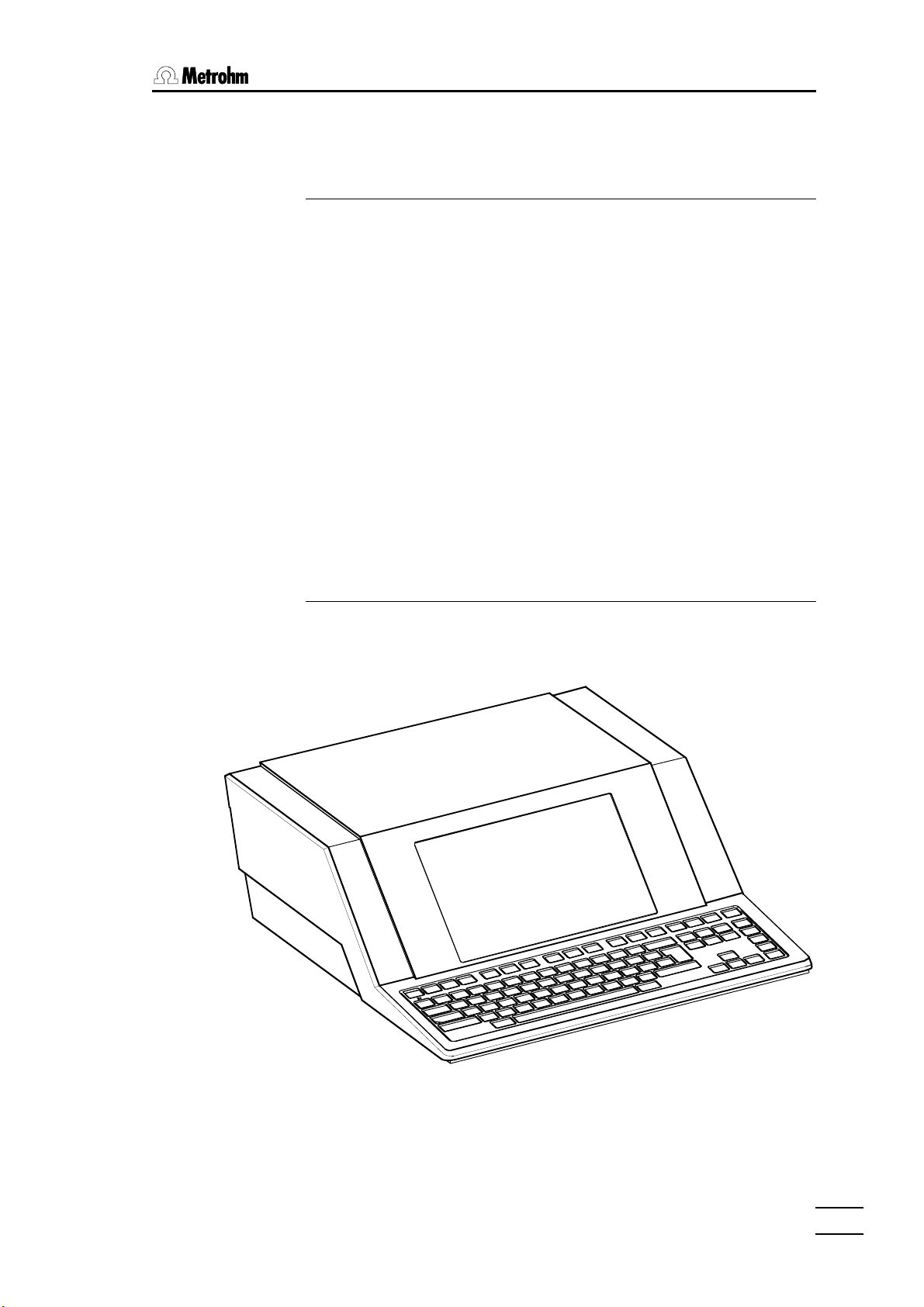
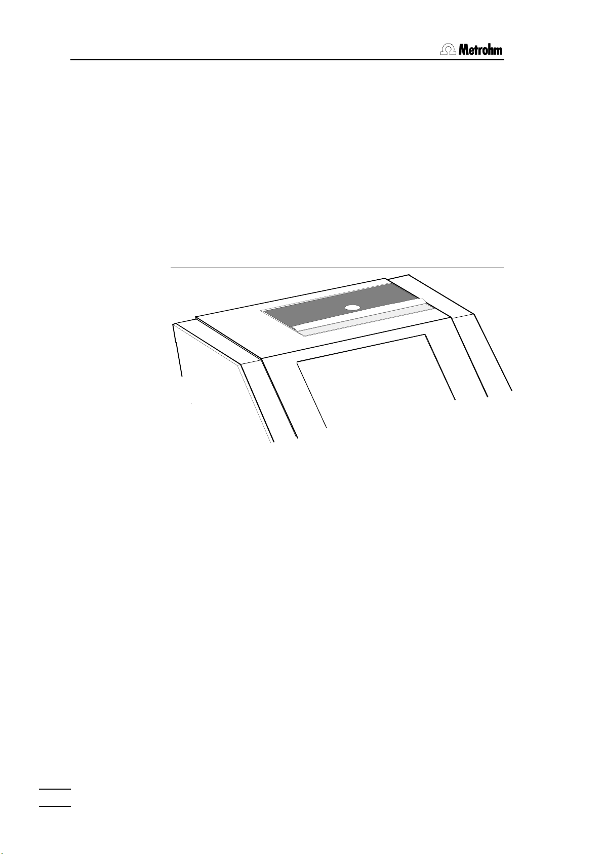
1.3.2 Front view
Model 2.726.0010 of the 726 Titroprocessor without built-in printer.
726 Titroprocessor, Instructions for use
33
Page 10
1.3 Instrument description
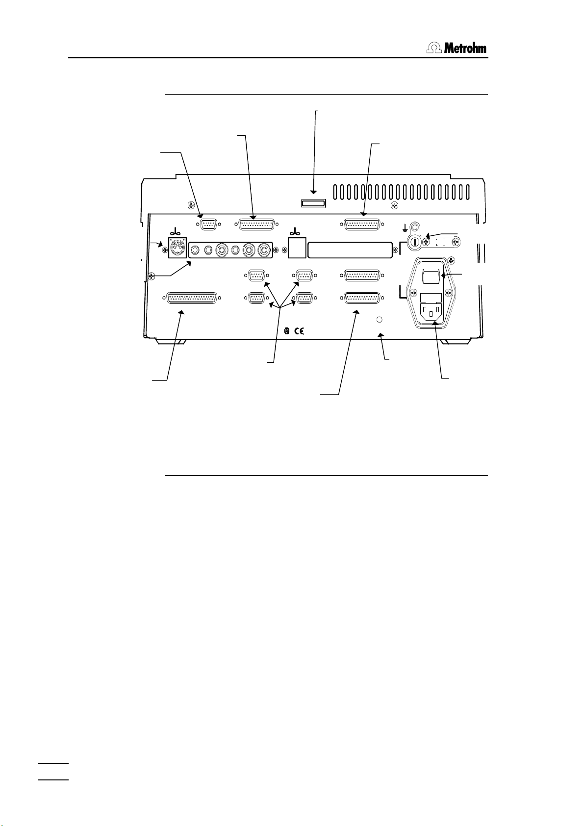
1.3.3 Rear view
Serial number
Bar-code
connector
Stirrer Int A
connector
Measuring
interface A
External bus
connector
Remote socket
Bar Remote Printer
Code
D E F
Ind A2 Ind A1 Ref Pol Pt100/1000 Ind B2 Ind B1 Ref Pol Pt100/1000
Sensors A Sensors B
Dos. A1
Dosing Units
External Bus
B
Made by Metrohm Herisau Switzerland 50-60Hz 160VA
Dos. A2
21
CC
Dos. A3
Dos. A4
A
Dosing unit
connectors
RS 232 communi-
cation interface
G
RS 232 Interface 1
RS 232 Interface 2
Printer connector
(parallel interface)
2A(TH)
115V230V
Reset
1
0
Reset
button
Type 1.726.0010
Fuse holder
Mains switch
Mains connector
1.3.4 Peripheral device connections
Instrument Interface designation Label
Balance RS 232 interface 1 or 2 G
Indicator electrodes Sensors A or B (Ind A1, Ind A2, ..) C
Indicator electrodes Sensors A or B (Ref) C
Temperature sensors Sensors A or B (Pt100/1000) C
Stirrer Sensors A or B C
Dosing devices Dosing units A
Sample changer External bus B
Dosing interface 729 External bus B
Printer (Centronics) Printer F
Printer (serial) RS 232 interface 1 or 2 G
Bar-code reader Bar-code D
Personal computer/LIMS RS 232 interface 1 or 2 G
Auxiliary instruments Remote E
44
726 Titroprocessor, Instructions for use
Page 11
11. Introduction. Introduction
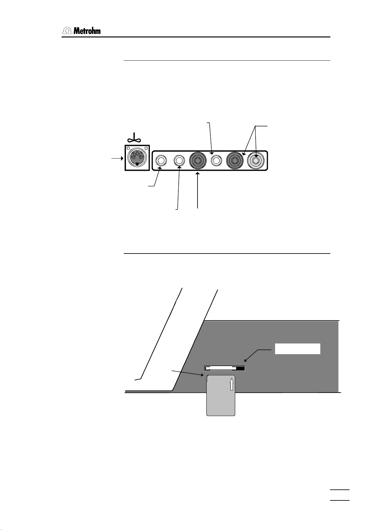
Notch
1.3.5 Measuring interfaces / Measuring inputs
The 726 Titroprocessor models 2.726.0110 and 2.726.0120 are equipped
with 2 measuring interfaces (Sensors A and Sensors B).
The diagram below shows where the sensors are to be connected to measuring interface A, which is found on all 726 Titroprocessor models.
Stirrer Int A con-
nector
Indicator electrode
Polarized
electrode
Pt100 / Pt1000
Temperature sensor
1
Ind A2 Ind A1 Ref Pol Pt100/1000
Sensors A
A2
Indicator electrode
A1
1.3.6 Data cards
Data cards can be used to store methods or measuring data and to transfer
them from one instrument to another. They are an excellent mobile storage
medium.
Reference
electrode
Right-hand side of housing
Eject button
Data
card
Attention must be paid to several points when handling data cards.
So-called PC cards which meet the Standard PCMCIA 2.x (68 Pins) / JEIDA
4.x can be used.
Flash cards can be read but not written on, e.g. the application card
(Order. no. 6.6024.000) supplied with the Titroprocessor
726 Titroprocessor, Instructions for use
55
Page 12
1.3 Instrument description
SRAM cards can be read and written on.
Card battery
Data cards are battery-buffered storage media. The battery must be
changed periodically in order to avoid data loss. Make a note of the expiry
date of the battery which is given on the leaflet accompanying the card.
Important:
The expiry date of the battery refers to a storage temperature of 25°C. At
higher storage temperatures the working life of the battery is shorter. Do not
carry the card next to your body; do not store it near a heater or expose it to
direct sunlight.
1.3.7 The built-in thermal printer
Capacity: 128 KB (Order no. 6.2245.010) to 2 MB.
Titroprocessor models with built-in printer (2.726.0020 and 2.726.0120) can
additionally have a second printer (or two) connected to an RS 232 interface. However, an additionally connected printer must have a serial interface
as Titroprocessor models with built-in thermal printers do not have a parallel
printer interface.
66
726 Titroprocessor, Instructions for use
Page 13
1.4 The keyboard
11. Introduction. Introduction
QUIT PRINT
ON
GLP
CAPS LOCK
OFF
STOP FORM
STOP
PG UP
NEXTDELAYSKIP
START
MAN
CONTROL
STATUS
METHOD
SAMPLE
RESULT
LINE
PRINT
FEED
SCREEN
F1 F2 F3 F4 F5 F6 F7 F8 F9
#@!
&
^$
)
(*
+
=-0987654321
µ
°
ENTER
REWQ
T
LKJHGFDSA
;
><
ALTALT
][POIUY
|":
,
\
?
/.,MNBVCXZ
HOLD
HELP
CONT
HOME
INS
DEL END PG DN
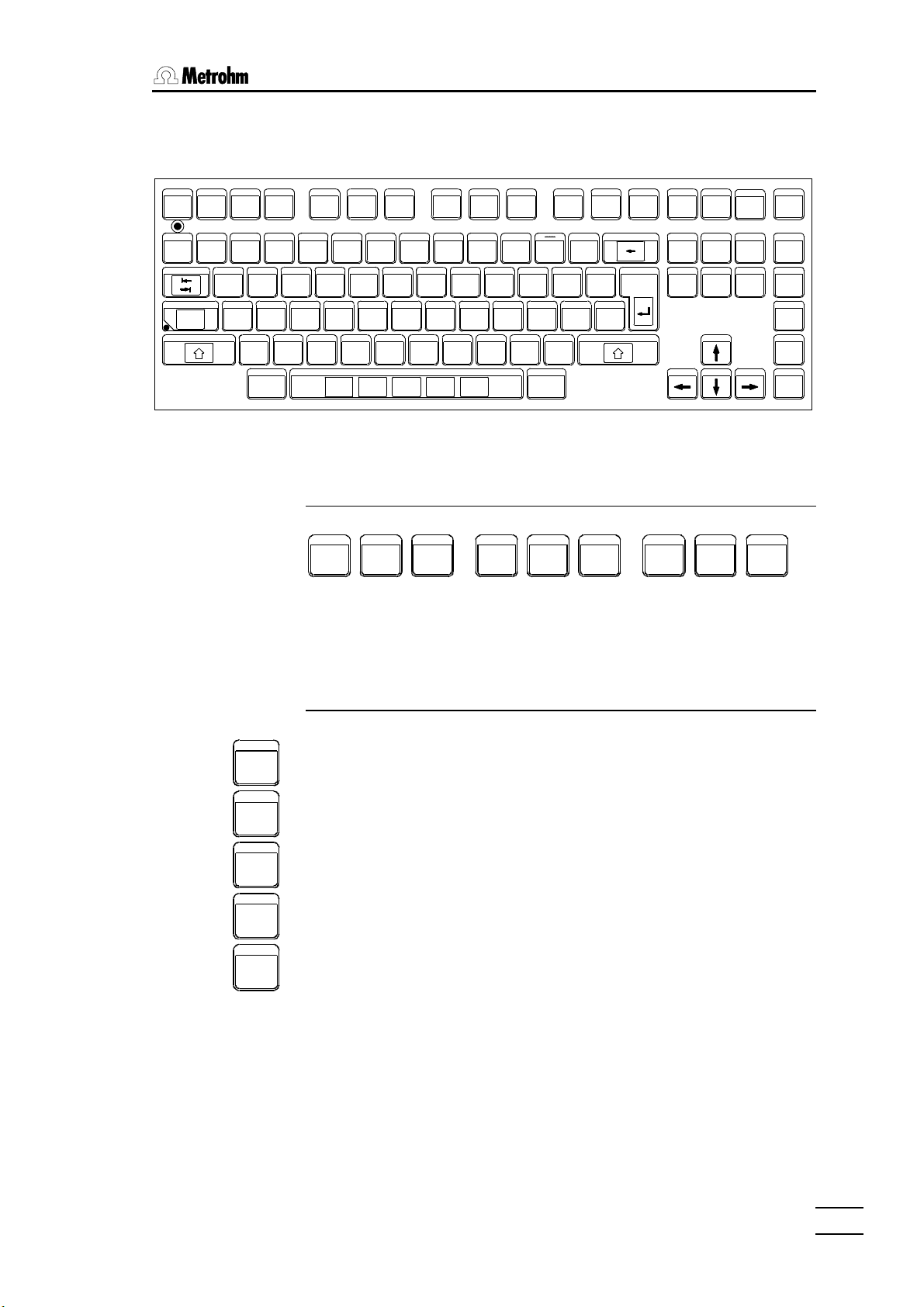
The PC-like keyboard allows comfortable editing and data input in method
development and routine use.
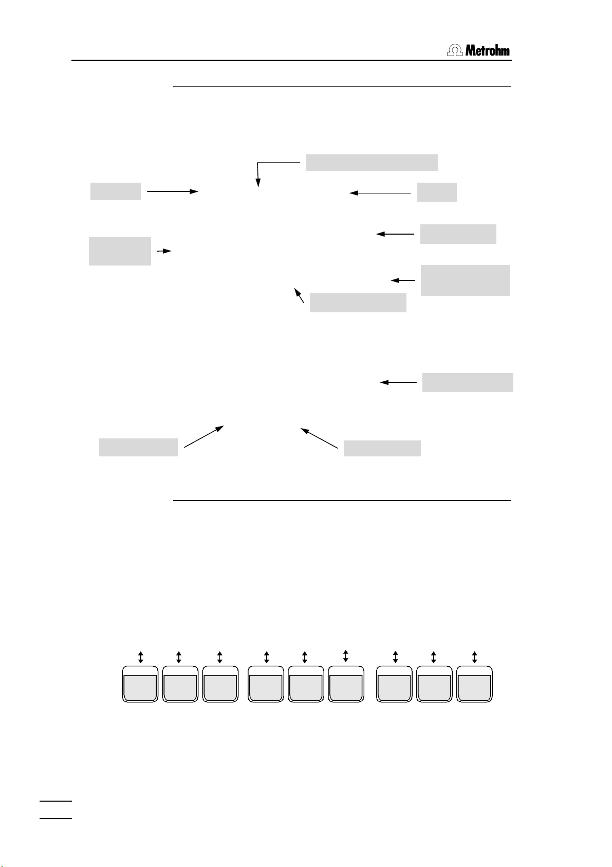
1.4.1 Function keys (softkeys)
F1 F2 F3 F4 F5 F6 F7 F8 F9
The blue function keys are used for navigation within the window-oriented
operator dialog system. The function of these keys depends on the dialog
page and the particular window. The softkey bar at the lower edge of the
screen always shows the possible functions.
MAN
CONTROL
STATUS
METHOD
SAMPLE
RESULT
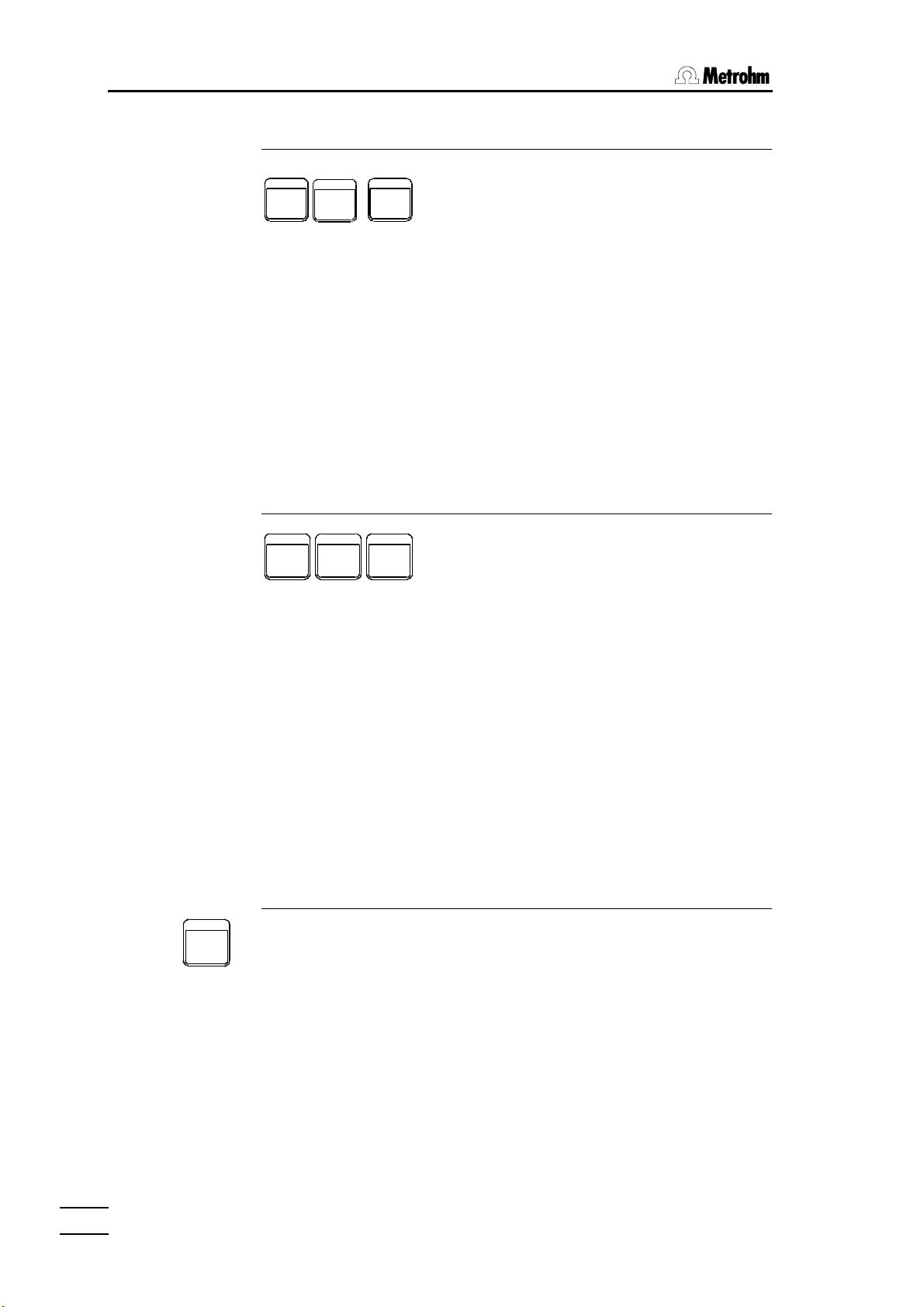
1.4.2 Hotkeys
The yellow hotkeys allow direct access to the most important functions or
dialog pages of the 726. Hotkeys can be used anywhere in dialog except
during the 'live' display of a curve while a determination is being carried out.
MAN CONTROL - opens the dialog page for manual operation
STATUS - displays the status information as shown on the main page
METHOD - opens the method selection window
SAMPLE - opens the sample input window
RESULT - opens a window which shows short result reports and statistics
726 Titroprocessor, Instructions for use
77
Page 14
1.4 The keyboard
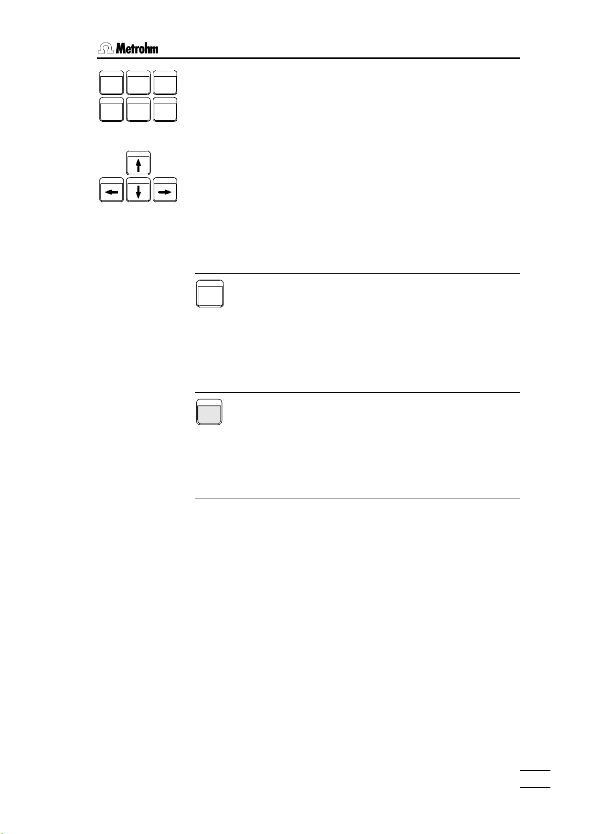
1.4.3 Action keys
NEXTDELAYSKIP
HOLD
CONT
STOP
START
The action key have an immediate effect on the course of a method. The
<START> key starts a method; the <STOP> key ends it. The <HOLD /
CONT> key can be used to interrupt a method or to resume it.
If the <Shift> key is pressed at the same time as an action key the processing of a series of samples can be controlled directly (with Autostart 'on').
<Shift><START> (=NEXT) ends the processing of the current sample and
starts processing the next sample in the series.
<Shift><STOP> (=DELAY) stops the sample series after the current sample has been processed.
<Shift><HOLD> (=SKIP) ends the execution of the current command and
jumps to the next command line of the loaded method.
1.4.4 Manual printing
QUIT
STOP FORM
PRINT
FEED
LINE
PRINT
SCREEN
The built-in A4 thermal printer or any other connected printer can be operated manually with the yellow printer keys.
The <PRINT><PRINT> key opens the printer menu where the type of report can be
selected. Global reports and determination reports (if a determination report
is present in the working menu) can be selected.
<Shift><PRINT> (= STOP PRINT) interrupts a printout immediately.
<LINE FEED> executes a line feed on the connected printer.
<Shift><LINE FEED> (= FORM FEED) executes a form feed on the con-
nected printer.
<PRINT SCREEN> prints the current screen contents.
1.4.5 Navigation and editing keys
The <QUIT> <QUIT> key closes an editing field, a window or a dialog page and
accepts previous parameter modifications. The dialog switches to the next
higher level.
<INS> (= Insert) switches the insert mode on/off for editing an entry
<<DEL> (= Delete) deletes the character to the right of the cursor position
<Shift><DEL> deletes a complete editing field.
<HOME> places the cursor on the first editing field of a dialog window (in
navigation mode).
<END> places the cursor on the last sample silo line or command line (in
method editor).
88
726 Titroprocessor, Instructions for use
Page 15
11. Introduction. Introduction
HOME
INS
DEL END PG DN
PG UP
<PG UP> moves the field cursor in the sample silo or method editor up by
one page.
<PG DN> moves the field cursor in the sample silo or method editor down
by one page.
<<Cursor up> moves the cursor up by one line.
<Cursor down> moves the cursor down by one line.
<Cursor left> moves the cursor one field (in navigation mode) or one char-
acter (in editing mode) to the left.
<Cursor right> moves the cursor one field (in navigation mode) or one
character (in editing mode) to the right.
1.4.6 HELP key
HELP
The <HELP><HELP> key opens a page with help texts which refer to the opened
dialog page or window. In the editing mode it opens a help window for parameter input.
1.4.7 The GLP key
GLP
The GLP key opens the dialog pages in which the basics functions for validating the Titroprocessor as an analytical system and for checking sensors
(sensor test) can be carried out.
1.4.8 Special key abbreviations
For certain functions special key combinations have been provided; these
are listed below.
ALT+↑↑ increase display contrast
ALT+↓↓ reduce display contrast
ALT+A opens a dialog window to enter the access control page
ALT+T transfer screen contents via the communications interface
(printscreen to RS 232 interface)
ALT+X transfer screen contents via the communications interface
(with screen attributes line by line)
ALT+U transfer screen contents via the communications interface
(with screen attributes character by character)
726 Titroprocessor, Instructions for use
ALT+V transfer field contents of a selected editing field via the
communications interface
SHIFT+ALT
+DEL Titrator restart (mains on)
99
Page 16
1.4 The keyboard
Entry of special charactersEntry of special characters
In the editing mode any character contained in the ASCII character set can
be entered. This is carried out by first entering the character ^^ and then the
3-place3-place number of the required character. This is then displayed immediately.
Examples:
αα →→ ^224^224
ββ →→ ^225^225
≈≈ →→ ^247^247
≥≥ →→ ^242^242
≤ ≤ →→ ^243^243
±± →→ ^241^241
The complete table of the characters which are possible and their character numbers:
032 048 0 064 @ 080 P 096 ``112 p 128 Ç 144 É 160 á 176 °° 192 ÀÀ 208 ÐÐ 224 αα 240 ≡≡
033 ! 049 1 065 A 081 Q 097 a 113 q 129 ü 145 æ 161 í 177 ±± 193 ÁÁ 209 ÑÑ 225 ββ 241 ±±
034 "" 050 2 066 B 082 R 098 b 114 r 130 é 146 Æ 162 ó 178 ²² 194 ÂÂ 210 ÒÒ 226 ΓΓ 242 ≥≥
035 # 051 3 067 C 083 S 099 c 115 s 131 â 147 ô 163 ú 179 ³³ 195 ÃÃ 211 ÓÓ 227 ππ 243 ≤≤
036 $ 052 4 068 D 084 T 100 d 116 t 132 ä 148 ö 164 ñ 180 ´´ 196 ÄÄ 212 ÔÔ 228 ΣΣ 244 ⌠⌠
037 % 053 5 069 E 085 U 101 e 117 u 133 à 149 ò 165 Ñ 181 µµ 197 ÅÅ 213 ÕÕ 229 σσ 245 ⌡⌡
038 & 054 6 070 F 086 V 102 f 118 v 134 å 150 û 166 ª 182 ¶¶ 198 ÆÆ 214 ÖÖ 230 µµ 246 ÷
039 '' 055 7 071 G 087 W 103 g 119 w 135 ç 151 ù 167 º 183 ·· 199 ÇÇ 215 ×× 231 ττ 247 ≈≈
040 ( 056 8 072 H 088 X 104 h 120 x 136 ê 152 ÿ 168 ¿ 184 ¸¸ 200 ÈÈ 216 ØØ 232 ΦΦ 248 °°
041 ) 057 9 073 I 089 Y 105 i 121 y 137 ë 153 Ö 169 ©© 185 ¹¹ 201 ÉÉ 217 ÙÙ 233 ΘΘ 249 ••
042 * 058 : 074 J 090 Z 106 j 122 z 138 è 154 Ü 170 ªª 186 ºº 202 ÊÊ 218 ÚÚ 234 ΩΩ 250 ⋅⋅
043 + 059 ; 075 K 091 [ 107 k 123 { 139 ï 155 ¢ 171 ½ 187 »» 203 ËË 219 ÛÛ 235 δδ 251 √√
044 ,, 060 < 076 L 092 \ 108 l 124 ¦ 140 î 156 £ 172 ¼ 188 ¼¼ 204 ÌÌ 220 ÜÜ 236 ìì 252 üü
045 -- 061 = 077 M 093 ] 109 m 125 } 141 ì 157 ¥ 173 ¡ 189 ½½ 205 ÍÍ 221 ÝÝ 237 ø 253 ²
046 .. 062 > 078 N 094 ^ 110 n 126 ~~ 142 Ä 158 žž 174 « 190 ¾¾ 206 ÎÎ 222 ÞÞ 238 εε 254 þþ
047 // 063 ? 079 O 095 _ 111 o 127 -- 143 Å 159 ƒ 175 » 191 ¿¿ 207 ÏÏ 223 ßß 239 ∩∩ 255
1010
726 Titroprocessor, Instructions for use
Page 17
1.5 Dialog
11. Introduction. Introduction
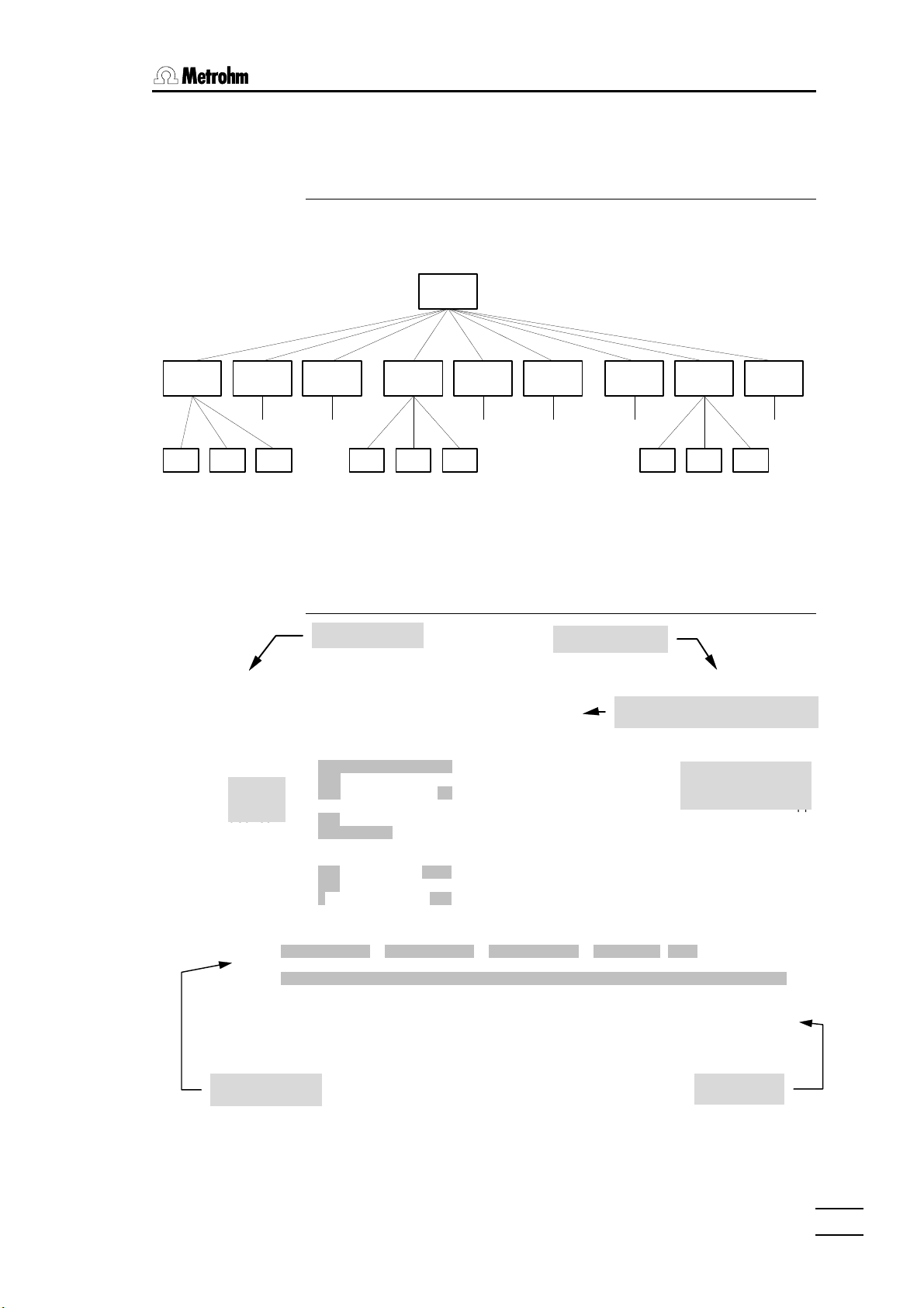
1.5.1 Dialog overview
The user dialog of the 726 Titroprocessor consists of 10 main pages, which
contain hierarchically structured subwindows.
Main
page
Sub-
window
Load
method
window
Sub-
Files
page
Sub-
window
Method
page
Sub-
window
sub-
window
Curves
page
Results
page
Samples
page
Sub-
window
Devices
page
Sub-
window
Sub-
window
Variables
page
Configuration
page
Sub-
window
The main page of the 726 Titroprocessor is the entry to the user dialog. All
other pages can be accessed by using the corresponding softkeys (<F1>
to <F9>).
1.5.2 The main page
Date and time
ЪДДДДДДДДДДДДДДДДДДДДДДДДДДДДДДДДДДДДДДДДДДДДДДДДДДДДДДДДДДДДДДДДДДДДДДДДДДДДДДД¿
³ 97-12-02 09:24:13 MAIN PAGE Titroprocessor 726 * ready * ³
³ ³
³ Method 3455.mth Chloride in Tap Water ³
³ ДДДДДДДДДДДДДДДДДДДДДДДДДДДДДДДДДДДДДДДДДДДДДДДДДДДДДДДДДДДДДДДДДДДДДДДДДДДДДД³
³ ³
³ Auto save on 1.7 % free ³ Pipet accurately 100.00 mL of sample in a ³³
³ Destination Data card ³ 150 mL beaker. ³³
³ Determ.name ³ ³³
³ ³ Reagent: c(HNO3)=2 mol/L Dos A2 ³³
³ Auto start on 1 of 10 ³ Titrant: c(AgNO3)=0,01 mol/L Dos A1 ³³
³ Silo on in# 12 out# 1 ³ Sensor : Ag-Titrode 6.0430.100 Ind A1 ³³
³ Changer 1 Sample pos. 1 ³ ³³
³ АДДДДДДДДДДДДДДДДДДДДДДДДДДДДДДДДДДДДДДДДДДДЩ³
³ ³
³ Ident1 Ident2 Ident3 Size Unit ³
³ Sample 971120/1 12 3455 100 mL ³
³ ³
³ Remark ³
³ ³
³ ЪДДДДДДДВДДДДДДДВДДДДДДД¿ ЪДДДДДДДВДДДДДДДВДДДДДДД¿ ЪДДДДДДДВДДДДДДДВДДДДДДД¿ ³
³ ³Config.³Load ³File ³ ³Edit ³Show ³Results³ ³Sample ³Devices³Common ³ ³
³ ³ ³method ³manager³ ³method ³curves ³ ³ ³silo ³ManCtrl³vars. ³ ³
³ АДДДДДДДБДДДДДДДБДДДДДДДЩ АДДДДДДДБДДДДДДДБДДДДДДДЩ АДДДДДДДБДДДДДДДБДДДДДДДЩ ³
АДДДДДДДДДДДДДДДДДДДДДДДДДДДДДДДДДДДДДДДДДДДДДДДДДДДДДДДДДДДДДДДДДДДДДДДДДДДДДДДЩ
³ ЪДДДДДДДДДД Application note ДДДДДДДДДДДДДДД¿³
³ User B. Miller ³ Chloride in Tap Water ³³
³ Run number 000 ³ ------------------------------------------³³
Status
³ Statistics on 0 of 10 ³ Sample preparation: ³³
³ ³ ³³
Area
Instrument state
Method name and comment
Application note
and trace window
Sample data
726 Titroprocessor, Instructions for use
Softkey bar
1111
Page 18
1.5 Dialog
command with line number
quantity
Measured value
F7
F4F3F2
1.5.3 The trace window
During the course of a method the display windows of the application note
changes to a trace window, showing the state of the currently executed
commands. The display format depends on the current command or mode.
Line time
Measuring
Control indicator
ЪДДДДДДДДДДДДДДДДД Trace ДДДДДДДДДДДДДДДДДДД¿
³ 0s 1. DET_PH* Titr. ³
³ ³
³ ЬЫЫЫЬ ЬЫ ЬЫ ³
³ Ы Ы Ы Ы ЫЯЫ ЫЯЫ ³
³ Ы Ы ЯЫЫЫЫ Ы ЫЯ Ы ³
³ ЫЫЫЬ ЫЫЫЫЫ Ы Ы Ы Ы ³
³ Ы Ы Ы Ы Ь Ы Ы ЫЫЫЫЫ ³
³ ЫЫЫЯ Ы Ы ЯЫЫЫЯ Ы ЫЫЫЫ Ы ³
³ Ы ³
³ Ы ³
³ 2.991mL 1 EP's ³
АДДДДДДДДДДДДДДДДДДДДДДДДДДДДДДДДДДДДДДДДДДДЩ
or
ЪДДДДДДДДДДДДДДДДД Trace ДДДДДДДДДДДДДДДДДДД¿
³ 0s 1. SET_PH* Titr. ³
³ ³
³ ЬЫ ЬЫЫЫЬ ЬЫЫЫЬ ЬЫЫЫЬ ³
³ ЫЯЫ Я Ы Ы Ы Ы Ы Ы ³
³ Ы ЫЫЯ ЯЫЫЫЫ ЯЫЫЫЫ Ы ³
³ Ы ЯЫ Ы Ы ЫЫЬЫЬ Ы ³
³ Ы Ь Ы Ь Ы Ь Ы Ы Ы Ы Ы ³
³ ЫЫЫЫ Ы ЯЫЫЫЯ ЯЫЫЫЯ ЯЫЫЫЯ Ы Ы Ы ЫЫЫЫ ³
³ ³
³ ЫЭЭЭЭЭЭ.............. ³
³ pH 9.81 ³
АДДДДДДДДДДДДДДДДДДДДДДДДДДДДДДДДДДДДДДДДДДДЩ
Dispensed volume
Status
Measured value
Equivalence points
found
Dispensed volume
1.5.4 How to navigate
To navigate from page to page or from subwindow to subwindow you can
use the blue function keys <F1> to <F9> . These function keys alter their
meaning or functionality, depending on the dialog page or window that is
shown on the screen. The function of the corresponding function key is always shown at the bottom of the screen. It is called the softkey bar. The
function keys (<F1> to <F9>) are called softkeys.
ЪДДДДДДДВДДДДДДДВДДДДДДД¿ ЪДДДДДДДВДДДДДДДВДДДДДДД¿ ЪДДДДДДДВДДДДДДДВДДДДДДД¿
³Config.³Load ³File ³ ³Edit ³Show ³Results³ ³Sample ³Devices³Common ³
³ ³method ³manager³ ³method ³curves ³ ³ ³silo ³ManCtrl³vars ³
АДДДДДДДБДДДДДДДБДДДДДДДЩ АДДДДДДДБДДДДДДДБДДДДДДДЩ АДДДДДДДБДДДДДДДБДДДДДДДЩ
F1
F6F5
F9F8
Allfällige Modifikationen der Parameter werden übernommen. A dialog page
or window can be left or closed by pressing the <QUIT> key. Any prior modifications of parameters will be accepted.
1212
726 Titroprocessor, Instructions for use
Page 19

The shortcut keys of the rightmost key column on the keyboard allow direct
access to some important dialog windows or features.
1.5.5 Field cursor
To navigate on a page or in a dialog window you can use the cursor keys
<ç>, <è>, <é> or <ê>. The position of the so called field cursor is
indicated by the black field background of the edit field the cursor is pointing to. To navigate right or left within a line you can use the <TAB> key or
the <Shift><TAB> key combination, respectively. The <HOME> key sets
the field cursor to the first edit field of a page or dialog window.
1.6 How to edit
To edit an entry of an edit field just type in the new value or press the
<SPACE> key. In most cases a picklist is shown, from which you can select
a given value by using the cursor keys <êê> and <éé>. The selection must
be confirmed with <ENTER> or the picklist may be closed by pressing the
<QUIT> key. The field cursor will turn into a block cursor which indicates the
edit mode.
The PC-like keyboard allows comfortable editing of text or numeric entries.
To erase any character use the <DEL> (forward deletion) or the
<BACKSPACE> key (<[ çç ]> backward deletion). The <INS> key switches
the insert mode to the overwrite mode and vice versa.
11. Introduction. Introduction
In this mode a special softkey bar is shown.
ЪДДДДДДДВДДДДДДДВД … ДВДДДДДДД¿
³Help on³Select ³ … ³Cancel ³
³entry ³ ³ … ³ ³
АДДДДДДДБДДДДДДДБД … ДБДДДДДДДЩ
• The [Help on entry] softkey may be used to open a window with a short
explanation of the meaning or the content of the entry field to be edited.
The entry range and one or more examples for entry values will be
shown.
• The [Select] softkey opens the picklist of the selected entry field. If no
picklist is available, the [Select] softkey is displayed in gray letters to indicate that its function is not available.
• The [Cancel] softkey rejects any modifications and resets the former
field content. The edit mode will be canceled as well.
Modifications of field contents are to be confirmed with the <ENTER> or the
<QUIT> key. The latter will terminate the edit mode.
726 Titroprocessor, Instructions for use
Tip:
If the edit mode (entry on the configuration page, or press the <INS>key) is
set to 'overwrite', you can simply type in the first letter or the first two letters
of an entry item and press <ENTER> to change the content of an entry field
with a selector list. If this entry can be uniquely assigned to an item of the
selector list, it will be automatically completed.
1313
Page 20

1.6 How to edit
Example:
To change the destination memory of data files for use with the auto save
function, set the field cursor to the destination field on the Titroprocessor's
main page. Type 'd' then and press the <ENTER>key. The entry of the de-
stination field will be set automatically to 'Data card'.
This is the quickest way to modify entry fields .
1.6.1 Navigation in edit mode
In edit mode the cursor keys <çç> and <èè> allow the navigation within an
entry field. To access other fields in the same line use the <TAB> key or the
<Shift><TAB> key combination, respectively. The cursor keys <êê> and
<éé> allow vertical navigation.
1414
726 Titroprocessor, Instructions for use
Page 21
2 Installation
2.1 Instrument setup
Packaging
The 726 Titroprocessor is supplied together with the specially packed accessories in packaging containing shock-absorbing foam which provides
excellent protection. Please store this special packaging as it guarantees
damage-free transport of the instrument.
Checks
Please check immediately on receipt whether the shipment is complete and
undamaged (compare with delivery note and list of accessories on page
290). If transport damage is established see section 13.7 Warranty
(p. 287).
22. . InstallationInstallation
Location
Place the 726 Titroprocessor in a convenient working position in the laboratory; this should be vibration-free and not exposed to corrosive atmospheres or contamination by chemicals.
2.2 Mains supply
Follow the instructions given below for connection to the mains
supply. If the instrument is operated with the mains voltage incorrectly set and/or the wrong mains fuse there could be a danger of
fire!
Setting the mains voltage
Before switching on the 726 Titroprocessor for the first time check that the
mains voltage set on the instrument (can be seen in the mains voltage selector) corresponds to the local mains voltage. The mains voltage selector is
located on the rear panel of the instrument: please refer to following page.
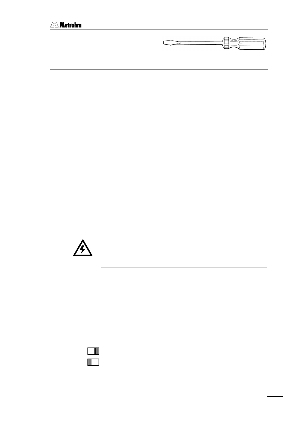
If the mains voltage is incorrectly set then it must be set correctly by sliding
the mains voltage selector with the help of a screwdriver:
230V
115V
726 Titroprocessor, Instructions for use
230V: 220V ... 240 V ± 10%
115V: 100V ... 120 V ± 10%
1515
Page 22
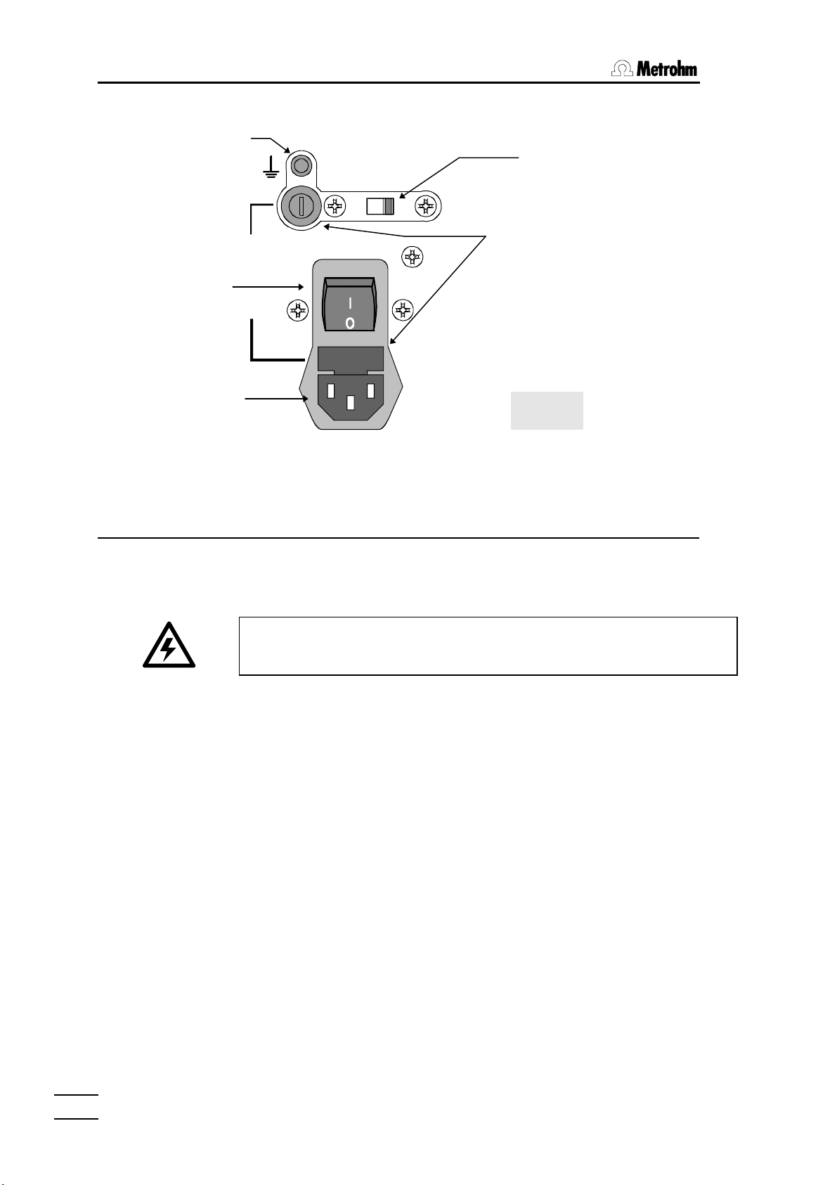
2.3 Mains connection
Earth socket
115V: 100V...120V 10%
230V: 220V...240V 10%
230V
Mains voltage selector
S1
2A(TH)
Mains switch
115V
230V
Mains connection
50-60Hz 160VA
2.3 Mains connection
2.3.1 Fuses
Two fuses S1S1 and S2S2 are built into the 726 Titroprocessor as standard;
both are type 2 ATH (2 A, slow-blow, with high switching capacity, Metrohm
order no. U.600.0107).
Make sure that the instrument is never operated with any different type
of fuse as otherwise there is a fire hazard!
S2
Fuse holder
Rear view
For continued protection replace only
WARNING - Fire Hazard -
with the same type and rating of fuse
1616
To change blown fuses proceed as follows:
Exchange fuse S1 (zero conductor, 2 ATH)
• Remove mains cable from mains connector.
• Use a screwdriver to turn fuse holder S1S1 to the left until it can be pulled
out.
• Pull out the fuse holder, remove the blown fuse and replace it with a
spare fuse (2 ATH).
• Insert the fuse holder in the instrument, press it down with a screwdriver
and then turn it to the right to fix it in position.
Exchange fuse S2 (phase, 2 ATH)
• Remove mains cable from mains connector.
• Use a screwdriver to push fuse holder S2S2 upwards until it can be pulled
out.
• Pull out the fuse holder, remove the blown fuse and replace it with a
spare fuse (2 ATH).
• Insert the fuse holder in the instrument and push until it clicks into place.
726 Titroprocessor, Instructions for use
Page 23
2.3.2 Mains cable and mains connection
The instrument is supplied with one of three types of cable:
• 6.2122.020 with plug SEV 12 (Switzerland, …)
• 6.2122.040 with plug CEE(7), VII (Germany, …)
• 6.2133.070 with plug NEMA 5-15 (USA, …)
which has three leads and is fitted with a plug with an earthing pin. If a different plug has to be fitted then the yellow/green lead (IEC standard) must
be connected to the earth (protection class 1). If no earthed socket is available then a proper earth connection must be made via the earthing socket
of the instrument.
Any break in the earthing lead, whether inside or outside the instrument, can cause the instrument to become a hazard!
Insert the mains cable into the mains connector of the 726 Titroprocessor.
2.3.3 Setting up the thermal printer
22. . InstallationInstallation
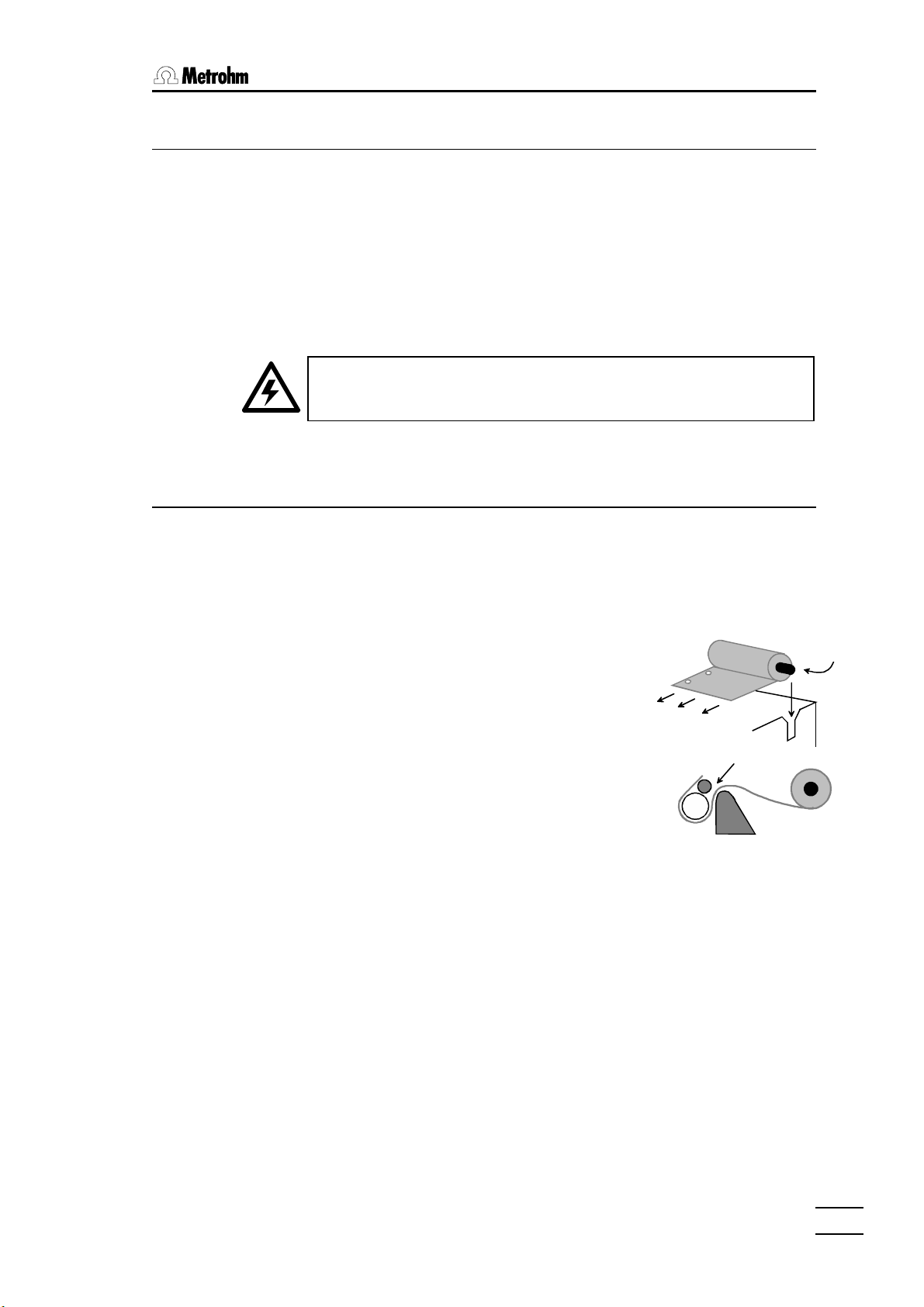
Insert paper (only for the built-in printer)
The thermal printer of the Titroprocessors (models 2.726.0010 and
2.726.0110) is supplied without inserted paper. The thermal paper
6.2237.040 included with the accessories (roll approx. 40 m ≅ 130 A4
pages) is inserted into the printer as follows:
Preparations
• Switch on 726 Titroprocessor.
• Lift up the printer cover.
• Make sure that the roll of thermal paper
6.2237.040 has a straight edge; if necessary,
carefully tear off the paper at the first perforation.
Insertion
• Insert paper spool 6.2241.020 in thermal paper roll 6.2237.040.
• Place the roll of paper with the paper spool in the two recesses at the
sides of the printer so that the paper leaves the roll from the rear and the
file hole margin is on the left-hand side when seen from the front.
• Carefully insert the straight-edged paper manually into the paper guide
slot to the limit stop and hold it there.
726 Titroprocessor, Instructions for use
Paper transport
• Press the two keys <Shift> and <FORM/LINE FEED>. The paper will
be fed in automatically and transported to the correct position.
• Close the cover of the paper storage compartment.
1717
Page 24
2.4 Data card handling (PC cards)
2.4 Data card handling (PC cards)
The 726 Titroprocessor can write data onto SRAM storage cards and read
this data in at a later date. The following data cards (memory cards) can be
used as storage cards:
• 6.2245.010 Metrohm Data card (capacity 128 kB)
• Commercial SRAM cards of any capacity with the hardware format
JEIDA 4.0 (68 pin) as well as PCMCIA cards based on them
Because of different file systems PCMCIA cards cannot be used at
the same time for the 726 Titroprocessor and PCs.
When handling data cards with the 726 Titroprocessor the following points
are important:
Data card preparation
The following preparations are necessary before data cards are used for the
first time:
• New data cards are supplied with a separately included battery. This
should be inserted in the data card according to the accompanying description.
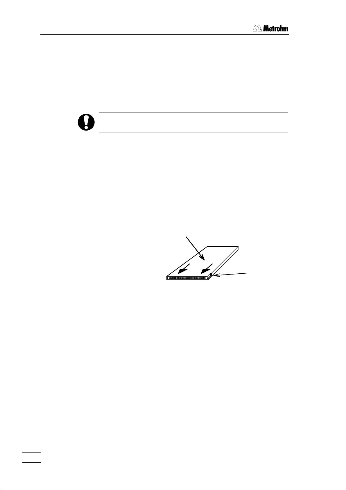
• Data cards can only be inserted in the instrument in the position shown
below. The included label should be attached to the top of the data card.
Label
Notch
• The data card battery has a limited life; this is given in the accompanying
leaflet. In order to avoid accidental loss of data, the date when the battery is due to be exchanged should be written on the data card label.
• Before data can be stored on the data card it must be formatted. Pro-
ceed as follows:
• Insert data card in the 726 Titroprocessor (see above drawing).
• Select file manager with the softkey [File manager] on the main
page. Change the memory area with the softkey [Change storage],
select 'data card' with the cursor keys and press <ENTER>.
• If an unformatted card has been inserted a system window appears
on the display. Enter <f> to format the card.
1818
• A query about the card name is then made. A name with max. 20
characters can be entered; this will now be displayed in the file manager whenever the card is inserted. When the entry has been completed the data card is formatted with <Enter>.
726 Titroprocessor, Instructions for use
Page 25
22. . InstallationInstallation
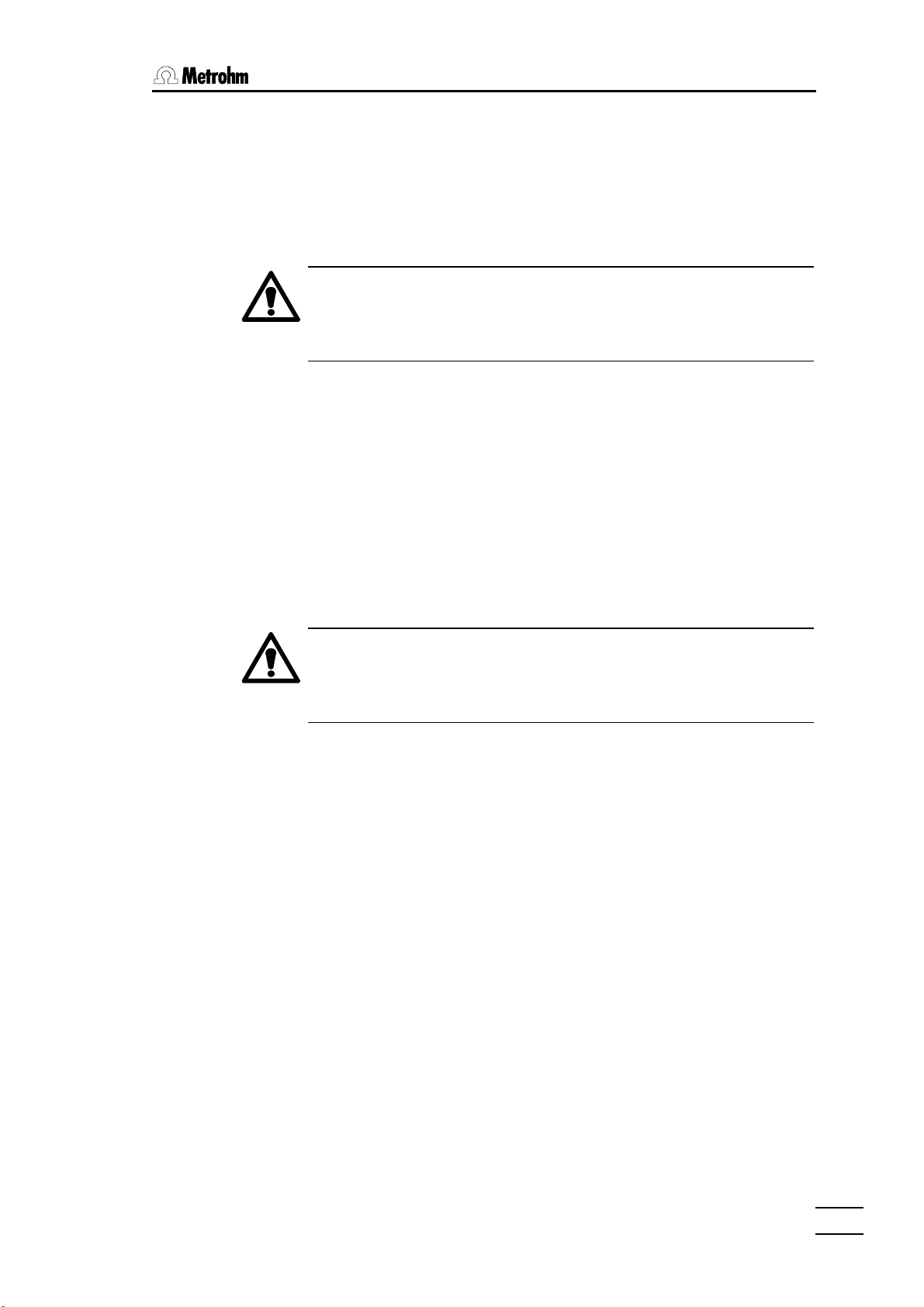
Data card insertion and removal
• The data card can only be inserted in den 726 Titroprocessor in one
particular position (see above illustration). It must be pressed firmly
into the slot provided until the eject button fully protrudes.
• A data card inserted into the Titroprocessor slot can be ejected by
pressing the eject button and then removed manually.
Data cards are sensitive to electrostatic charges. Make sure that
you are earthed each time you insert or remove a data card (e.g.
by previously touching the earthed green 726 Titroprocessor
housing).
Changing the battery
• The battery of the data card has a limited working life which is given
in the leaflet accompanying the card. Please note that the working life
of batteries depends on the storage temperature. Data cards or
spare batteries should therefore be stored as cool as possible (in any
case below 25°C).
• The date for the next battery change should be marked on the data
card label (see above). In order to avoid accidental data loss the
battery should be replaced by this date at the latest.
• Insert the data card in the 726 Titroprocessor.
The battery must only be exchanged with the card inserted in the
instrument, as otherwise the data stored on the card will be lost.
The card is powered by the Titroprocessor while the battery is being changed.
• Change the battery according to the accompanying description.
• Mark the data card label with the new date for the next battery
change (see under ”data card preparation” above).
726 Titroprocessor, Instructions for use
1919
Page 26
2.5 Safety information
2.5 Safety information
If failure or malfunctioning occurs during operation of the 726 Titroprocessor
we recommend that the diagnostic functions are first used to try and determine the cause (see page 260). If this does not help to rectify the failure or if
the cause of the malfunction cannot be remedied then please consult the
service department of your local Metrohm agency.
If opening the instrument cannot be avoided then the following safety
measures must be strictly observed:
The instrument must be disconnected from all electricity supplies before opening. Make sure the mains plug has been pulled
out.
Only in exceptional cases should the instrument be opened while it is
switched on. As this exposes current-conducting components it should only
be undertaken by an expert who is familiar with the associated dangers.
Electronic components are sensitive to static electricity and can be destroyed by discharges. Before touching any components inside the instrument both the person and his tools should be earthed by grasping an
earthed object (e.g. the instrument housing or a radiator) in order to eliminate any static electricity.
If it becomes apparent that the instrument can no longer be operated safely
then it should not be used at all.
2020
726 Titroprocessor, Instructions for use
Page 27
2.6 Connections
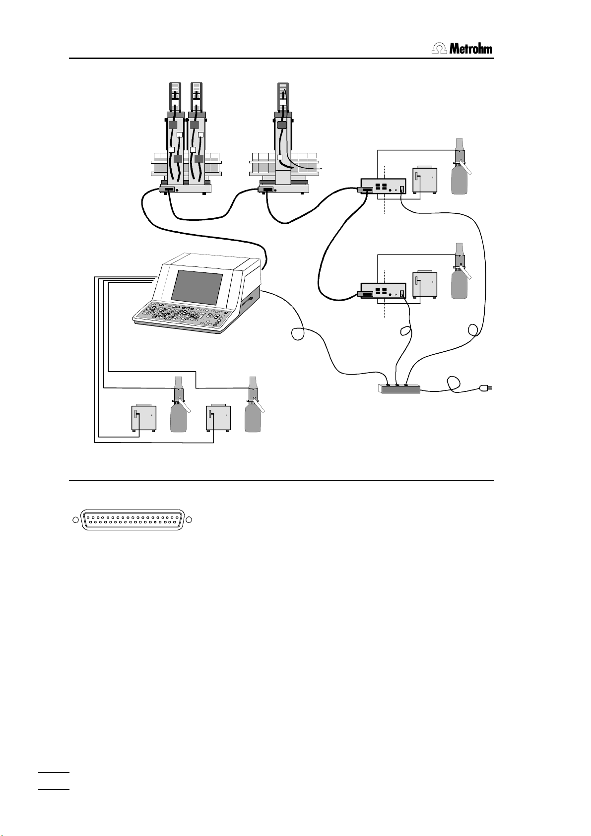
2.6.1 System components and peripheral devices
717 Sample changer
22. . InstallationInstallation
external
devices
external
devices
external
devices
717 717
External bus
726
Dosinos /
Dosimats
700685 700685
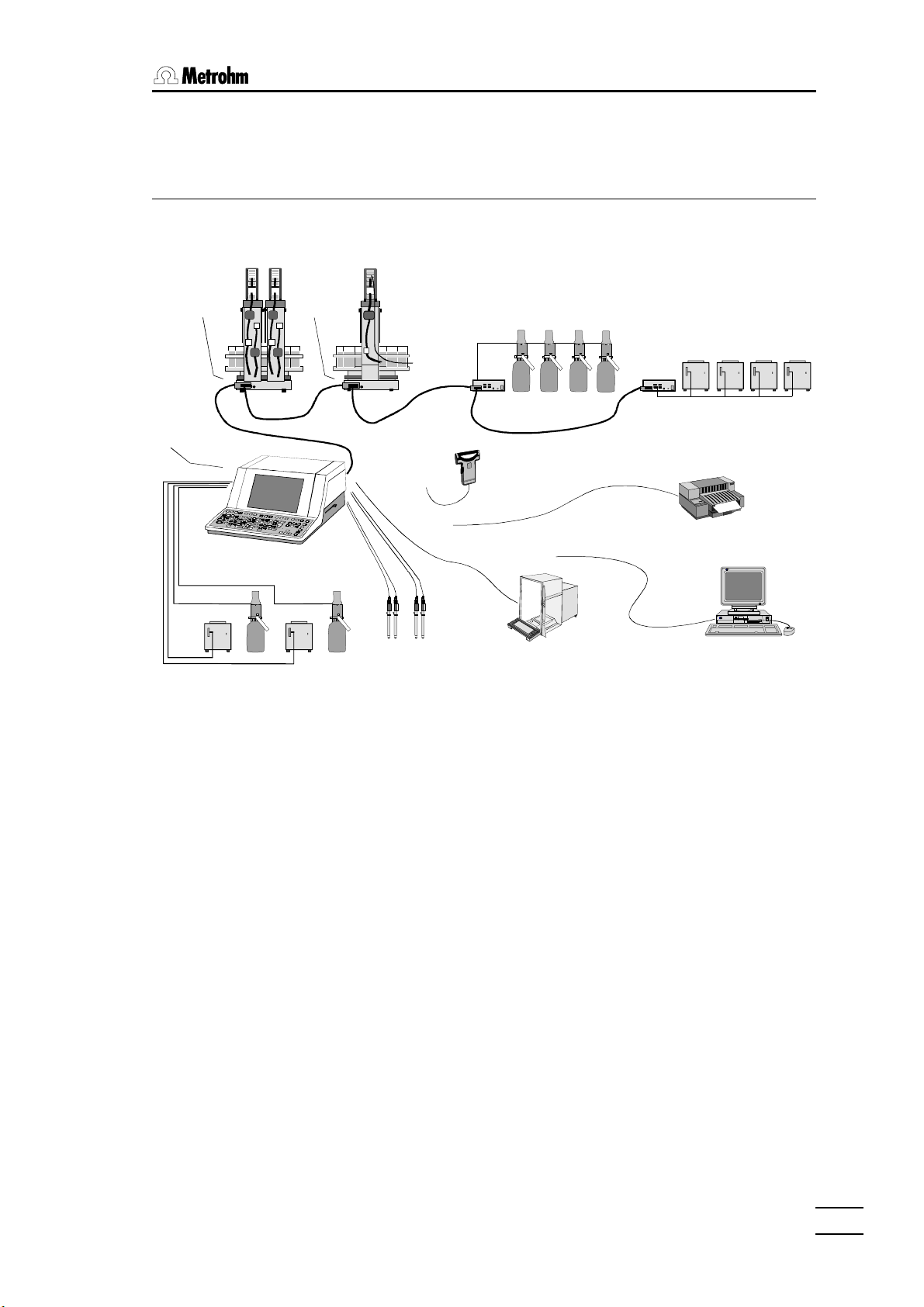
The 726 Titroprocessor can be extended to provide an automated and
comprehensive analytical system.
sensors
700 Dosinos
700
729
729 Dosimat
interfac
bar-code reader
700
balance
700
700
729
729 Dosimat
interfac
685 Dosimats
685
685
printer
PC / LIMS
685 685
726 Titroprocessor, Instructions for use
Metrohm cables should always be used to connect Metrohm instruments
and accessories, as only these guarantee interference-free data transmission. For instruments from other manufacturers please observe the manufacturer's recommendations.
The Titroprocessor offers the following connections:
• 4 dosing devices, further (up to 8) dosing devices can be connected via
the 'External bus' (see below).
• 2 measuring groups (models 2.726.0010 and 2.726.0020 have only 1
measuring group) each with measuring inputs for 2 indicator electrodes
(or combined measuring electrodes), 1 reference electrode, 1 polarizable electrode (voltammetry/amperometry, KF titrations), 1 Pt100/Pt1000
temperature sensor connection, 1 stirrer connection
• 1 'External bus' connection for up to two 717 Sample changers and/or
up to 8 dosing devices, to be connected via Dosimat interfaces 729 (4
dosing devices per interface)
• 2 serial RS 232 connections (25-pole) for balance, printer or personal
computer (LIMS, automatic data storage or remote control of the 726 Titroprocessor)
2121
Page 28
2.6 Connections
• 1 parallel printer connection for any external printer (only for models
• 1 bar-code reader connection (9-pole) for entering sample data
• 1 remote connector (25-pole) with 8 input and 8 output leads for control-
2.6.2 Dosing devices
2.726.0010 and 2.726.110)
ling external peripheral devices (e.g. Relay Box, KF Oven, etc.). Each
717 Sample changer has a further remote connector (25-pole) with 8 input and 14 output leads which can be directly addressed from the 726
Titroprocessor.
Dos. A1
Dos. A3
Up to 4 dosing devices can be
directly connected to the rear panel
of the Titroprocessor. For connecting a 685 Dosimat you need a
6.2134.000 cable.
Dos. A2
Dosing Units
A
Dos. A4
Dosing devices are recognized by
the addresses A1 to A4.
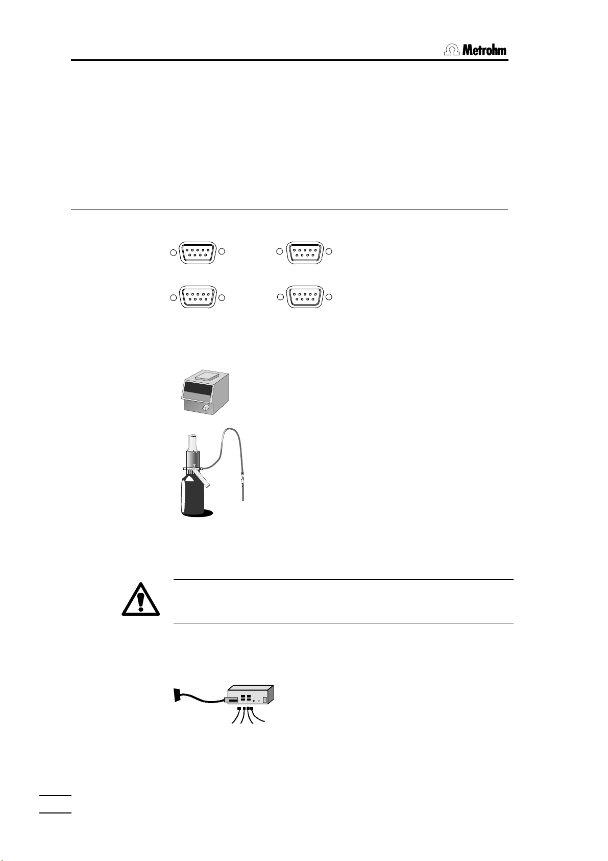
Two different types of Metrohm dosing device are available for selection:
• 685 Dosimat, with the normal exchange units.
• 700 Dosino, with 710 dosing unit
700 Dosino
10 ml
Dosinos are operated by the 726 Titroprocessor
in the standard configuration, i.e. the reagent is
drawn in from the bottle via Dosino port 2 (filling
port) and added via port 1 (dosing port). The port
occupancy cannot be changed when a Dosino is
used with the 726 Titroprocessor.
2222
685 Dosimats and 700 Dosinos can be combined
as required.
Switch off the 726 Titroprocessor before connecting an instrument
to it. When it is switched on again the Titroprocessor automatically
recognizes the new instrument.
If more than four dosing devices are to be connected then the additional
dosing devices should be connected via 729 Dosimat interface to the
'External bus' (for connections see sample changer below).
729
Plug the 729 Dosimat interface directly into the 'External bus' socket of the
Titroprocessor or, if installed, into the corresponding socket of the
717 Sample changer.
726 Titroprocessor, Instructions for use
Page 29
2.6.3 External bus
22. . InstallationInstallation
The external bus allows external instruments to be controlled by the 726 Titroprocessor. Sample changers and dosing devices such as the 685 Dosimat or the 700 Dosino can communicate bi-directionally with the Titroprocessor (=bus master).
External devices must be connected with EBus cables according to the following scheme:
Bus master
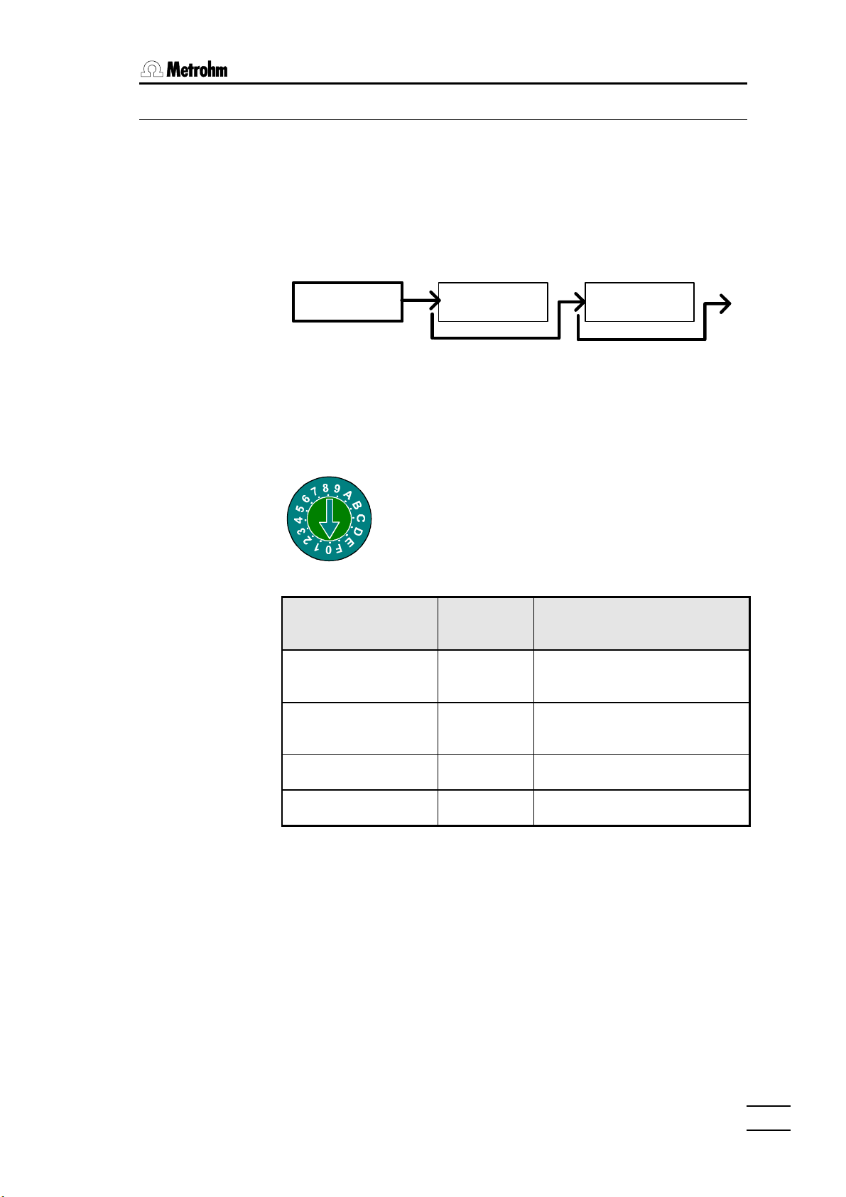
Each external instrument is identified by an EBus address. When the Titroprocessor is switched on they are automatically identified. An EBus address
must be set for each external device (1…9, A…F; 0 stands for the bus
master).
External device EBus
Sample changer 1
External device External device
External bus
Address selector
The corresponding EBus address can be set with
a screwdriver. The EBus address selector is usually located on the rear panel of the external device.
Corresponding
address
1
1…2 lifts, 0…4 pumps,
1…4 stirrers
peripherals
726 Titroprocessor, Instructions for use
Sample changer 2
Dosimat interface 1
Dosimat interface 2
Devices such as sample changers which consume a lot of current should
be connected in the first position of the EBus chain. This is particularly important if the relevant sample changer is equipped with more than one
pump. The 729 Dosimat interfaces should be connected to the 717 Sample
changer.
The 726 Titroprocessor and the Dosimat interfaces must be connected to
the same earth. A line distributor should be used to supply all devices on
the external bus.
The 726 Titroprocessor must be switched off before a peripheral device is connected.
2
1
2
1…2 lifts, 0…4 pumps,
1…4 stirrers
1…4 Dosimats (B1…B4)
1…4 Dosimats (C1…C4)
2323
Page 30
2.6 Connections
Dosing
devices
Dosimat A2
Dosimat A1
717 717
EBus
Address 1
External Bus
726
Dosimat A3
700685
Dosimat A4
700685
EBus
Address 2
Dosimat B3
EBus
Address 1
729
Dosimat B4
Dosimat C3
EBus
Address 2
729
Dosimat C4
Power cables
Line distributor
Dosimat B1
700685
Dosimat B2
Dosimat C1
700685
Dosimat C2
2.6.4 Sample changers
B
External Bus
One or two 717 Sample changers can be connected to the 'external
bus' sockets of the 726 Titroprocessor. Take care that the address
selector disk is set correctly (see above). Please connect up larger
systems according to the above diagram.
Two 717 Sample changers can be connected at the same time;
however, they cannot be used simultaneously in one automatic
method. It is possible to change the active sample changer within a
method (see command 'CHANGER').
Manual operation of a sample changer while the other sample
changer is busy carrying out a method is possible and does not
present any problems.
2424
726 Titroprocessor, Instructions for use
Page 31

2.6.5 Sensors / Electrodes
1
Titroprocessor models 2.726.0110 and 2.726.0120 are supplied with two
built-in measuring interfaces (Sensors A and Sensors B). The models
2.726.0010 and 2.726.0020 only have one measuring interface (Sensors A)
but can be extended to two measuring interfaces at a later date with
upgrade set 6.5855.000.
The different measuring inputs of a measuring interface:
• Ind A1, A2
Input for indicator or measuring electrodes (single and combined electrodes) for potentiometric determinations.
It is possible to carry out a manual measurement at one measuring input
while the second input is carrying out a titration.
22. . InstallationInstallation
Ind A2 Ind A1 Ref Pol Pt100/1000
Sensors A
• Ref
Separate reference electrode input. If combined electrodes are used this
electrode input is not required.
• Pol
Connection for polarized electrodes for amperometric and voltametric
determinations (measuring modes Upol or Ipol).
• Pt100/1000
Inputs for Pt100 or Pt1000 temperature sensors (also used for electrodes
with built-in Pt100 or Pt1000 sensors).
• Stirrer connection
Stirrer power supply (12 V, 250 mA) for operation without sample
changer. Can be used with 728 Magnetic stirrer, 722 Rod stirrer and 727
and 703 Titration stands.
The measuring inputs Ref, Ind A1 and Ind A2 (or B1, B2) can be used together as a differential amplification switch for differential potentiometry. This
is recommended for measurements or titrations in low-conductivity media
(e.g. organic solvents).
726 Titroprocessor, Instructions for use
2525
Page 32

2.6 Connections
2.6.6 Connecting a balance
G
RS 232 Interface 1
The following balances can be connected to an RS 232
interface of the 726 Titroprocessor:
RS 232 Interface 2
Balance Cable
Sartorius MP8, MC1 6.2125.070
Mettler AB, AG, PR LC-RS25, supplied with balance
Mettler AM, PM from Mettler: ME 33995: green wire to pin 2, brown to pin
3, white to pin 7, yellow to pin 20 of the 25-pole plug
Mettler interface 016 cable supplied with interface 016: red wire to pin 3, white
wire to pin 7 of the 25-pole plug
Mettler interface 011 or 012 6.2125.020
Mettler AT from Mettler: ME 33995: green wire to pin 2, brown to pin
3, white to pin 7, yellow to pin 20 of the 25-pole plug
AND types ER-60, 120, 180, 182
6.2125.020
types FR-200, 300
types FX-200, 300, 320
with RS 232 interface (OP-03)
Precisa, balances with RS 232C in-
terface
The type of balance must be entered in the Titroprocessor on the configuration page under [Interfaces].
6.2125.080
2626
726 Titroprocessor, Instructions for use
Page 33

22. . InstallationInstallation
The data transmitted from the balance are directly interpreted by the 726 Titroprocessor within the permitted input range for the sample weight including sign and decimal point. The units given in the following table are also
accepted:
Gram
Milligram
Kilogram
Pieces
Pieces
Carat
Pound
Ounce
Troy ounce
Grain
Pennyweight
g
mg
kg
pcs
PC
ct
lb
oz
ozt
GN
dwt
Units which are not listed and
which are transmitted directly
after the weight cannot be interpreted and will therefore be
rejected.
Any control characters which the balance may transmit will cause the Titroprocessor to produce an error message. Switch off all your balance's automatic status messages when it is connected to the 726 Titroprocessor.
With the aid of a special input unit supplied by the balance manufacturer it is
possible to enter the sample identification and method from the balance as
well as the sample weight. This is done by preselecting the addresses of the
identification and method on the input unit.
BalanceBalance MethodMethod Ident1Ident1 Ident2Ident2 Ident3Ident3
Sartorius METH or 27 ID.1 or 26 ID.2 or 24 C-20 or 23
Mettler (AT) D (Mthd)
C (ID#1) B (ID#2)
A (c20)
726 Titroprocessor, Instructions for use
2727
Page 34

2.6 Connections
2.6.7 Connecting an external printer
There are various ways of connecting an external printer to the 726 Titroprocessor.
Parallel printer interface (only for models 2.726.0010 and 2.726.0110)
Commercial printers for PCs (e.g. inkjet printers from Hewlett-Packard, Epson, Canon) can be connected without any problems to the 'Printer' connection on the rear panel of the Titroprocessor with the cable supplied by
the manufacturer.
So-called GDI printers (e.g. HP Deskjet 620 or 820) are specially
designed for use under MS-Windows© and can only be used under
MS-Windows© . They cannot be used with the 726 Titroprocessor.
Printer
F
Printer on the serial RS 232 interface
G
RS 232 Interface 1
RS 232 Interface 2
It is also possible to connect an external printer to models 2.726.0020 and
2.626.120. Printers which have their own serial RS 232 interface can be
connected directly to 'RS 232 Interface 1' or 'RS 232 Interface 2' with the
aid of cable 6.2125.050 (e.g. Epson LX-300).
If necessary commercial printers with a parallel Centronics interface can be
connected to one of the RS 232 interfaces of the Titroprocessor by means
of serial/parallel converter SP 1000 (2.145.0300). In addition a serial
6.2125.020 connection cable is required. Depending on the type of printer a
9V mains adapter for the SP 1000 converter and possibly an extension
cable between the converter and printer may be required. Please consult
your local Metrohm agency.
2828
726 Titroprocessor, Instructions for use
Page 35

22. . InstallationInstallation
The following table shows the settings and cables needed to connect printers to one of the serial interfaces.
Printer Cable RS232 settings Printer settings
IBM Proprinter
6.2125.050
or
compatibles
Epson
6.2125.040
with 6-pole
round plug
Epson LX-300 6.2125.050
HP Deskjet
with serial interface
HP Laserjet
with serial interface
(and compati-
6.2125.050
or adapter cable 25-pol.neg.
/ 9-pol.pos.
(e.g. HP
C2933A)
6.2125.050 or
adapter cable
25-pol. neg. /
9-pol. pos. (e.g.
HP C2933A)
Baud rate: 9600
Data bit: 8
Stop bit: 1
Parity: none
Handshake: HWshort
Printer: IBM Propr.
Baud rate: 9600
Data bit: 8
Stop bit: 1
Parity: none
Handshake: HWshort
Printer: Epson 80x60
Baud rate: 9600
Data bit: 8
Stop bit: 1
Parity: none
Handshake: HWshort
Printer: Epson 80x60
Baud rate: 9600
Data bit: 8
Stop bit: 1
Parity: none
Handshake: HWshort
Printer: HP Deskjet
Baud rate: 9600
Data bit: 8
Stop bit: 1
Parity: none
Handshake: HWshort
Printer: HP Deskjet
see printer manual
DIP switch settings:
SW1 SW2
on
off
1 2 3 4 5 6 7 8 1 2 3 4 5 6 7 8
see printer manual
DIP switch settings:
A B
on
off
1 2 3 4 5 6 7 8 1 2 3 4 5 6 7 8
see printer manual
bles)
HP Deskjet/
Laserjet
with parallel
interface
6.2125.020 +
serial/ parallel
converter
2.145.0300
Baud rate: 9600
Data bit: 8
Stop bit: 1
Parity: none
Handshake: HWshort
Printer: HP Deskjet
see printer manual
2.6.8 Connecting a bar-code reader
Barcode
D
A bar-code reader can be connected to the bar-code reader socket on the
rear panel of the Titroprocessor. It can be used as a data input and transmits the coded data directly to the keyboard buffer of the Titroprocessor.
The plug occupancy and the transmission parameters of the reader must
correspond with the Metrohm specifications, see page 284. Please consult
your local Metrohm agency to obtain a list of recommended bar-code readers.
2.6.9 Devices on the remote interface
External peripheral devices such as pH meters, pumps, etc. can be controlled via the remote interface (25-pole socket) of the Titroprocessor. Each
717 Sample changer also has a remote socket which can be controlled via
the 'External bus'.
726 Titroprocessor, Instructions for use
2929
Page 36

2.6 Connections
Remote
E
8 lines are available for signal output (Output 0-7). The remote socket of the
717 Sample changer has 14 output lines available (Output 0-13).
For receiving signals (e.g. the "ready" signal from a Metrohm instrument)
there are 8 lines available (Input 0-7).
The pin occupancy of the remote socket:
InputsInputs
active= low
inactive = high
OutputsOutputs
active = low
inactive = high
0 Volt
+5 Volt
Output 5
Output 3
Output 1
Output 12
Output 13
Input 0
Input 2
Input 4
Input 6
0 Volt
Output 6
Output 7
Output 4
Output 2
Output 0
Output 8
Output 9
Output 10
Input 1
Input 3
Input 5
Input 7
Output 11
+5V
The control lines of the 726 Titroprocessor are purely signal leads (TTL-level)
and should not be misused for supplying devices.
Remote connections can be used with specially assembled cables to solve
complex connection problems in automated systems.
Connection of Metrohm instruments is solved in the following manner with
6.2141.020 Standard remote cable6.2141.020 Standard remote cable
726726 Metrohm instrumentMetrohm instrument ³ 726726 Metrohm instrumentMetrohm instrument
³
Output 0 ––––––– Input 0 ³ Input 0 ––––––– Output 0
Output 1 ––––––– Input 1 ³ Input 1 ––––––– Output 1
Output 2 ––––––– Input 2 ³ Input 2 ––––––– Output 2
Output 3 ––––––– Input 3 ³ Input 3 ––––––– Output 3
Output 4 ––––––– Input 4 ³ Input 4 ––––––– Output 4
Output 5 ––––––– Input 5 ³ Input 5 ––––––– Output 5
Output 6 ––––––– Input 6 ³ Input 6 ––––––– Output 6
Output 7 ––––––– Input 7 ³ Input 7 ––––––– Output 7
Output 8 ––––––– Pin 6
Output 9 ––––––– Pin 7
Output 10 ––––––– Pin 8
Output 11 ––––––– Pin 13
Output 12 ––––––– Pin 19
Output 13 ––––––– Pin 20
Output lines 8…13 can only be used
with the 717 Sample changer, but are
not used as input lines for Metrohm instruments. They are laid 1:1 on Pin
6…8,13,19…20.
3030
For the individual model series of Metrohm instruments different connection
cables are available with which the specific functions of the particular instrument can be addressed. On request Metrohm can supply special cables in accordance with the customer's wishes with which complex connections can be made (even to instruments from other manufacturers).
726 Titroprocessor, Instructions for use
Page 37

22. . InstallationInstallation
The 8 or 14 output lines of the remote socket can be set at will both in manual operation and during a method run with the "CONTROL" command
(CTRL_RM) by setting an 8 or 14-place bit pattern in which each bit is allocated to an output line. The output lines can also be set manually.
Output 13 12 11 10 9 8 7 6 5 4 3 2 1 0
Bit 13 12 11 10 9 8 7 6 5 4 3 2 1 0
(Bits are always numbered from right to left)
Example: CTRL_Rm Remote A Signal *******1
sets output line 0 to active (=set) which, for example, if a
Metrohm Ion meter is connected would have the effect of a
start command.
0 = inactive (high)
1 = active (low)
* = no change
It is recommended that non-relevant output lines are masked with an asterisk (*) so that the status of the line is not changed.
The 8 input lines of the remote socket can be scanned during a method with
the "Scan" command (SCAN_RM). Execution of the method is stopped
until the pre-determined bit pattern coincides with the effective condition of
the input lines (e.g. the status of the ready line, for querying the end of a
determination from a Metrohm instrument). This is done by setting an 8place bit pattern in which each bit is allocated to an input line. When they
coincide the method will be continued with the next command. In manual
operation the status display of all input lines can be scanned.
Input 7 6 5 4 3 2 1 0
Bit 7 6 5 4 3 2 1 0
(Bits are always numbered from right to left)
Example: SCAN_RM Remote A Signal *******1
waits for an active input line 0 (1=set). This line will be set by
e.g. a Metrohm instrument when a determination has been
finished and a start signal can again be accepted.
0 = inactive (high)
1 = active (low)
* = arbitrary
Input lines which are not of interest or for which no defined status can be
predicted should also be masked with an asterisk (*) here.
726 Titroprocessor, Instructions for use
3131
Page 38

2.6 Connections
With a suitable multiple cable (with special wiring) even several instruments
can be controlled simultaneously via the remote lines. The bit patterns for
the CTRL_RM and SCAN_RM commands can be combined for this pur-
pose.
2.6.10 LIMS connection
An RS 232 interface can be used for connecting the 726 Titroprocessor to a
LIMS system (Laboratory Information Management System). 6.2125.060
Connection cable (25-pole to 25-pole) or 6.2125.010 is connected to RS
232 interface socket 1 or 2. The serial connection COM1 or COM2 on the
Personal Computer must be used.
During the configuration of the interfaces (softkeys [Config.]
[Interfaces]) take care that no other instrument (balance or printer) has
been defined for the same connection. Under 'Communication Int.'
enter the corresponding RS 232 interface (1 or 2). Under 'Commun.
mode' enter 'LIMS'. The remaining data transmission parameters must
be set the same for both the PC and the Titroprocessor.
Reports cannot just be printed out but can also be sent directly to the LIMS
system.
3232
726 Titroprocessor, Instructions for use
Page 39

3 Configuration
In order to guarantee problem-free work with the 726 Titroprocessor it is
essential that the basic settings of all instrument components are
configured according to your requirements.
3.1 Basic settings
By pressing the softkey [Config.] the basic configuration can be
accessed from the main page.
ЪДДДConfiguration ДДДДДДДДДДДДДДДДДДДДДДДДД(Program version 5.726.0012)ДДДДДДДД¿
³ ³
³ Dialog in english Date 1997-12-04 ³
³ Time 16:05:52 ³
³ LCD contrast 100 ³
³ Screen save 30 min Standard data file name DATA ³
³ File name type <Ident1>.### ³
³ Error beep on File comment type Ident1,2+Meth+Remark ³
³ Edit beep on ³
³ Edit mode insert Power on PREP warning on ³
³ ³
³ Remote terminal mode off ³
³ File transfer protocol Metrohm(Bkup) ³
³ ³
³ ³
³ ³
³ ³
³ ³
³ ³
³ ³
³ ³
³ ³
³ ³
АДДДДДДДДДДДДДДДДДДДДДДДДДДДДДДДДДДДДДДДДДДДДДДДДДДДДДДДДДДДДДДДДДДДДДДД QUIT ДЩ
ЪДДДДДДДВДДДДДДДВДДДДДДД¿ ЪДДДДДДДВДДДДДДДВДДДДДДД¿ ЪДДДДДДДВДДДДДДДВДДДДДДД¿
³Device ³File ³Access ³ ³Sample ³Inter- ³Config.³ ³Tubings³ ³ >> ³
³header ³ ³control³ ³changer³faces ³idents.³ ³ ³ ³ >> ³
АДДДДДДДБДДДДДДДБДДДДДДДЩ АДДДДДДДБДДДДДДДБДДДДДДДЩ АДДДДДДДБДДДДДДДБДДДДДДДЩ
3. Configuration
The basic settings for the Titroprocessor 726 can be configured on this
dialog page. The softkeys allow access to the configuration of further
components.
Dialog in Dialog language. English, German, French and
Spanish are available. After changing the dialog
language the instrument should be switched off and
then back on again.
LCD contrast Contrastcan be selected in 250 steps.
The contrast can also be set with the key
combinations <ALT><éé> and <ALT><êê>.
Screen save Delay period for switching the screen off. If no key
on the Titroprocessor is pressed within the set period
then the background illumination of the LCD screen
will be automatically switched off (for its own care).
Pressing a key switches it on again.
Error beep Acoustic error message signal on/off
Edit beep Acoustic editing error message signal on/off
Edit mode Switches between overwrite/insert mode during data
input
726 Titroprocessor, Instructions for use
3333
Page 40

3.1 BasicBasic settings
Date System date in format YYYY-MM-DD
Time System time in format hh:mm:ss
Settings for determination files:
Each determination is automatically allocated a file name . There are various
ways of creating this file name. Combinations of determination time/date,
run number, sample identification and/or a particular standard text can be
defined.
Standard
data file name Standard text, which can be used for automatically
naming determination files. The file names are
produced automatically under file name type during
the determination according to the given mask.
file name type Mask for the automatic creation of file names for
determination files. The selection list:
<stand.>###.dtm standard+run number
<standard>.dtm only standard file name
<standard>.### standard+run number
<YYMMDDhh>.### date+ run number
<ident1>.### sample identification+
run number
<ident1>.dtm only sample identification
YYMMDDhh.mms date+time
Example:
Standard file name = 'DATA'
Run number = 005
<stand.>###.dtm
à à produces the file name: DATA005.dtm
The subsequent determinations in the same series
of samples are given the file names DATA006.dtm,
DATA007.dtm etc.
Please note that only the combination Date+Time
guarantees that a particular file name can never be
used twice.
File
comment type Mask for automatic creation of file comments for
determination files.
The selection list:
off no file comment
Remark only sample remark
Ident1+Meth sample identification+
method name
Ident1,2+Meth sample identification+
method name
3434
726 Titroprocessor, Instructions for use
Page 41

3. Configuration
Ident1,2,3+Meth sample identification+
method name
Ident1+Remark sample ident.+ remark
Ident1,2+Remark etc.
Ident1,2,3+Remark …
Ident1+Meth+Remark …
Ident1,2+Meth+Remark …
The scheme for the automatic creation of file
comments corresponds to that for automatic file
name creation, see above.
Power on
PREP warning If this warning is switched on this means that
immediately after the Titroprocessor is switched on a
display window appears with a reminder that a
dosing device must be prepared before the start of a
sample series , i.e. the buret must be rinsed with
reagent.
Remote
terminal mode This mode can be switched on by the remote control
of the Titroprocessor 726 via the RS232 interface. It has the effect of
sending the screen contents with all character attributes as ANSI control
sequences via the RS232 interface as soon as an alteration to the screen
contents occurs.
File transfer
protocol For data storage of determination or other files on a
personal computer two different data transfer
protocols are available. If Metrodata 726 backup
software is used then 'Metrohm (Bkup)' should
be selected, otherwise select 'Kermit'. This latter
requires that a PC terminal program is used which
supports this data transfer protocol.
726 Titroprocessor, Instructions for use
Softkeys
[Device
header] opens the dialog window for the entry of an
instrument-specific, four-line header, which will be
printed out before the report of a determination.
[File] opens the file dialog window for storing and loading
configuration files. It is recommended that all the
instrument configuration settings are stored on a
data card in this way. In a configuration file all the
subordinate areas on the configuration page are
stored in addition to the common variables. The rack
tables of special racks are not stored and, if
necessary, must be separately loaded with the help
of rack files, see page 40.
3535
Page 42

3.1 BasicBasic settings
In this way it is possible to reconstruct the whole
configuration of the Titroprocessor at a later date, or
to install the same settings on different instruments.
When loading a configuration file the individual
configuration areas can be selected for individual
take-over.
[Access
control] opens, after the corresponding password has been
entered, the configuration page for definition of the
access control. Individual keys on the keyboard as
well as most of the softkeys on the dialog pages can
be blocked or blinded out. Details can be found on
page 271.
[Interfaces] opens the configuration window of the interfaces.
The transfer parameters of the RS232 interfaces can
be entered here and the definition of balances and
printer set. Details can be found on page 44.
[Config
idents.] opens the configuration window of the sample
identification fields. The titles of the fields (Ident1…3)
can be freely selected. The field types determine
whether the contents of the sample identification
fields are to be interpreted as text or as numerical
values. In the latter case the sample identifiers
(system variables ID1…3) can be used in calculation
formula, see page 118ff.
If the sample silo is switched on then the definitions
of the sample identification fields in the sample silo
are valid. See also page 96.
3636
[Buret
unit] opens the configuration window of the buret units. In
order to use the dosing functions preparation
(PREP) and empty (EMPTY) in an optimal way it is
necessary to define buret units in which the tubing
dimensions and other settings for this function are
fixed. Details can be found on page 46ff.
[>> >>] switches to the second softkey bar.
[Service
diagn.] opens the dialog window for instrument diagnosis . It
is possible to test the various instrument
components and functions in order to check the
functional capabilities of the Titroprocessor 726.
Instrument diagnosis should be carried out with
great care as improper handling could result in
important data being deleted. Certain of the
diagnostic functions are reserved for our service
technicians.
Instrument diagnosis is described on page 260ff.
726 Titroprocessor, Instructions for use
Page 43

It is recommended that all the files in the internal
memory as well as the configuration settings (see
softkey [File]) are stored on data cards or on a
PC before the diagnosis function is carried out.
[>> >>] switches to the second softkey bar.
3.2 Configuration of sample changers
In order to guarantee reliable sample changer operation it is important that
the settings of the connected sample changer 717 and the sample racks
used are configured correctly.
By pressing the softkey [Config.] and then the softkey [Sample
changer] the configuration of the sample changer can be accessed from
the main page.
ЪДДДConfiguration ДДДДДДДДДДДДДДДДДДДДДДДДД(Program version 5.726.0012)ДДДДДДДД¿
³ ЪДДД Configuration: Sample changer ДДДДДДДДДДДДДДДДДДДДДДДДДДДДДДДДД¿ ³
³ Dial³ ³ ³
³ ³ Rack definitions ³ ³
³ LCD ³ # Name Beakers Special positions Type Code ³ ³
³ LCD ³ Work Shift Rinse Spec. ³ ³
³ ³ ДДДДДДДДДДДДДДДДДДДДДДДДДДДДДДДДДДДДДДДДДДДДДДДДДДДДДДДДДДДДДДДДД ³ ³
³ Fehl³ 1 12*250mL 12 0 mm 0 mm 0 mm 0 mm M12-0 000001 ³ ³
³ Edit³ 2 16*150mL 16 0 mm 0 mm 0 mm 0 mm M16-0 000010 ³ ³
³ Edit³ 3 24*75mL 24 0 mm 0 mm 0 mm 0 mm M24-0 001000 ³ ³
³ ³ 6 12*150mL 12 0 mm 0 mm 0 mm 0 mm M12-0 100000 ³ ³
³ ³ 5 14*8oz 14 0 mm 0 mm 0 mm 0 mm M14-0 000101 ³ ³
³ ³ 4 14*200mL 14 0 mm 0 mm 0 mm 0 mm M14-0 000011 ³ ³
³ ³ 7 19*100mL 19 0 mm 0 mm 0 mm 0 mm M19-0 001001 ³ ³
³ ³ 8 0 mm 0 mm 0 mm 0 mm ³ ³
³ ³ 9 0 mm 0 mm 0 mm 0 mm ³ ³
³ ³ 10 0 mm 0 mm 0 mm 0 mm ³ ³
³ ³ 11 0 mm 0 mm 0 mm 0 mm ³ ³
³ ³ 12 0 mm 0 mm 0 mm 0 mm ³ ³
³ ³ 13 0 mm 0 mm 0 mm 0 mm ³ ³
³ ³ 14 0 mm 0 mm 0 mm 0 mm ³ ³
³ ³ 15 0 mm 0 mm 0 mm 0 mm ³ ³
³ ³ 16 0 mm 0 mm 0 mm 0 mm ³ ³
АДДДДДАДДДДДДДДДДДДДДДДДДДДДДДДДДДДДДДДДДДДДДДДДДДДДДДДДДДДДДДДДДДД QUIT ДЩIT ДЩ
ЪДДДДДДДВДДДДДДДВДДДДДДД¿ ЪДДДДДДДВДДДДДДДВДДДДДДД¿ ЪДДДДДДДВДДДДДДДВДДДДДДД¿
³Delete ³ Rack ³ ³ ³Special³Changer³Changer³ ³Delete ³Delete ³ Check ³
³type ³ File ³ ³ ³beakers³ 1 ³ 2 ³ ³line ³ all ³ code ³
АДДДДДДДБДДДДДДДБДДДДДДДЩ АДДДДДДДБДДДДДДДБДДДДДДДЩ АДДДДДДДБДДДДДДДБДДДДДДДЩ
3. Configuration
726 Titroprocessor, Instructions for use
3737
Page 44
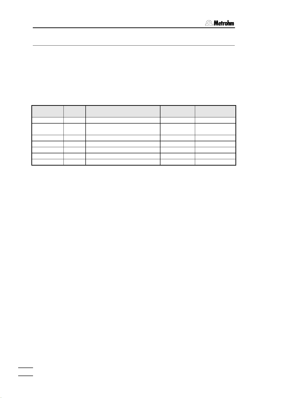
3.2 ConfigurationConfiguration of sample changers
3.2.1 Sample racks
A sample rack is a turntable which accepts sample beakers and which is
placed on the sample changer. As different sizes of sample beaker may be
required for different applications it is possible to use various types of
sample rack which can be easily exchanged for one another. Depending on
the diameter of the sample vessel, different racks provide space for different
numbers of samples. Multi-row sample racks can accept a larger number of
samples if a 759 Swing head is used. Metrohm supplies the following
predefined standard types of sample rack, among others:
Type No. of
samples
M12-0 12
M12-0 12
*)
*)
Type of sample vessel Magnet code
Order number
predefined
250 ml Metrohm sample beaker 000001 6.2041.310
150 ml beaker or
100000 6.2041.360
200 ml disposable beaker (Euro)
M14-0 14 200 ml disposable beaker (Euro) 000011 6.2041.370
M14-0 14 8 oz disposable beaker (US) 000101 6.2041.380
M16-0 16 150 ml beaker 000010 6.2041.320
M24-0 24
M48-1 48
*)
**)
75 ml Metrohm sample beaker 001000 6.2041.340
75 ml Metrohm sample beaker 010000 6.2041.350
*)
simultaneous sample processing at two sample changer towers possible.
**)
two-row rack for use with a 759 swing head .
On request further racks defined by the operator can be supplied and their
rack tables loaded into the Titroprocessor. Irregular arrangements of the
beaker positions are also possible.
Each individual sample rack can be unambiguously identified by means of
the magnet code. Magnetic rods, located on the base of the rack, can be
combined to form a binary 6-place code. This means that the sample
changer can identify the rack automatically. This is possible when the
sample rack is positioned with the first beaker position under Lift 1. When a
rack is changed the <MAN CONTROL> key should first be activated and
then the sample changer brought to the initial position with the softkeys
[Sample changer][Reset]. In this way the definite recognition of the
rack and thus the correct positioning of the beakers is possible.
When a series of samples is started the sample changer automatically
brings the rack to the initial position first so that a clear recognition of the
particular rack is always guaranteed.
3838
The standard racks supplied by Metrohm are already provided with a
predefined magnet code for each type of rack. If several racks of the same
type are to be used then the magnetic rods can be arranged differently to
enable the unambiguous identification of a particular sample rack, should
this be required.
The format of the magnet code (example):
000001 i.e. only one magnet is inserted in the outer right-hand position
or bit 0
000101 i.e. two magnets are inserted, bits 0 and 2
726 Titroprocessor, Instructions for use
Page 45

3. Configuration
63 different combinations are possible. Code 000000 stands for 'no code
defined'.
Magnets inserted
In this
example the code is:
000110
In order to allocate a certain sample rack to a particular application it is
possible to define particular properties or characteristics for up to 16 racks.
This makes sense when an application requires a particular size of vessel,
size of sample series or a particular procedure in order for the method to be
carried out.
The following characteristics can be defined for each rack:
Rack name The rack namerack name is used for the unambiguous identification
of a rack. The command 'Changer' in the method run
can be used to stipulate the use of a particular rack. The
automatic rack recognition ensures that the use of an
incorrect sample rack is recognized and that the operator
is informed of this.
Beakers The number of beaker positions is obtained from the rack
table. It does not need to be entered.
Special positions
For the lift stations of a changer tower particular „stopping points“, i.e.
predefined lift positions can be laid down:
Work The work position is used for fixing the position of the
titrating head (lift), in which e.g. a titration can be carried
out. Depending on the height of the sample beaker the
ideal setting can always be selected for each sample
rack. In manual operation this work position can be
moved to directly by means of the <PG DN>key.
Shift The shift position is used to fix the position of the
titrating head (lift) in which the sample rack can be
rotated. If the lift is not at or is above the shift position
then the sample rack cannot be rotated. This is a safety
measure as damage to the sensors caused by rotary
movement of the rack is practically ruled out. A
precondition is the correct setting of the shift position. In
manual operation this shift position can be moved to
directly with the <PG UP>key.
726 Titroprocessor, Instructions for use
3939
Page 46

3.2 ConfigurationConfiguration of sample changers
Rinse The rinsing position is used to fix the position of the
Spec. The special position is a further special position which
Type The rack typerack type is used for the assignment of an internal
Code The rack code is used for automatic rack recognition. In
titrating head (lift) at which the sensors can be rinsed at
the titrating head.
can be defined for each lift. It can be used individually in
a method run.
rack table in the instrument in which the positions of the
sample beakers are defined on the rack in tenths of
degrees (0-3599) of the complete rotary angle. Operatordefined special racks can be ordered from Metrohm.
Their rack tables could for example be loaded from a data
card, see softkey [Rack File].
The input fields for this column have a selection list (press
space bar), in which the rack types stored in the
instrument are listed. Newly added special rack types are
included in it automatically.
the configuration of the rack it must be guaranteed that
this 6-place binary code is identical with the magnet code
set on the rack. Rack codes can be altered. They should
only be allocated to one particular rack. The use of the
predefined codes which are standard on the racks
supplied by Metrohm should be avoided.
Softkeys
[Delete
type] deletes the special rack type which has been selected
with the cursor from the list of stored rack tables. The rack
types preset as standards cannot be deleted.
[Rack File] opens the file dialog window for loading a rack file (*.rck)
which contains the position table of a special rack. The
storage area from which the file is loaded can be selected
in the entry field 'Storage'. After the loading process
the name of the new rack type appears in the selection
list of the entry field 'Type'.
[Special
beakers] opens the dialog window for entering one of the eight
possible special beakers of the selected rack. The
corresponding rack must first be selected with the cursor
before the softkey is activated.
[Changer 1] opens the dialog window for the definition of the basic
settings of the 1st sample changer.
[Changer 2] opens the dialog window for the definition of the 2nd
sample changer.
[Delete
line] deletes the selected line or rack definition.
4040
726 Titroprocessor, Instructions for use
Page 47

[Delete
all] deletes all rack definitions.
[Check
code] carries out a short test to check whether a rack code has
3.2.2 Special beakers
Special beakers are the reserved beaker positions of a sample rack. Up to 8
special beakers can be defined per rack. In a method run they can be
placed in front of a tower for particular operations without interrupting
hindering the sample series. Special beakers can be used for rinsing the
electrode in a sequence of samples or to calibrate a sensor in an (OMOVE
start sequence (buffer solutions).
Special beakers are moved in front of tower 1 with the following command.
MOVE_B Special beaker spec1 to tower 1
3. Configuration
been allocated more than once. If this is the case then a
corresponding error message will be displayed.
Reserved special beaker positions, which can be defined separately for
each rack, are recognized as such in a method run and skipped when the
individual sample beakers are being processed.
If a special beaker is required in a method run but no special beaker is
present in the reserved position at the sample changer then an error
message is always displayed.
The softkey [Special beakers] opens the dialog window in which the
special beaker positions in the selected sample rack can be edited.
ÚÄÄÄ Rack 1 ДДДДДДДДДДДДД¿
³ ³
³ # Spec.beaker Position ³
³ ДДДДДДДДДДДДДДДДДДДДДД ³
³ 1 Rinse 12 ³
³ 2 Cond. 11 ³
³ 3 spec.3 0 ³
³ 4 spec.4 0 ³
³ 5 spec.5 0 ³
³ 6 spec.6 0 ³
³ 7 spec.7 0 ³
³ 8 spec.8 0 ³
АДДДДДДДДДДДДДДДДД QUIT ДЩ
Spec.beaker Freely selectable name of the special beaker.
726 Titroprocessor, Instructions for use
Position Rack position of the special beaker (0=not defined)
It is recommended that special beakers are not placed
in the first rack positions but in higher rack positions.
4141
Page 48

3.2 ConfigurationConfiguration of sample changers
3.2.3 Basic configuration of 717 Sample changer
The softkeys [Changer 1] and [Changer 2] open the dialog window
for the definition of the basic configuration of the sample changer.
ÚÄÄÄ Changer 1 ДДДДДДДДДДДДДДДДДДДДДДДДДДДДДДДДДДДД¿
³ ³
³ Tower 1/2 max. height 235 mm ³
³ ³
³ Tower 1 : 1 Pump[s] ³
³ Swing head no ³
³ ³
³ Tower 2 : 1 Pump[s] ³
³ ³
³ Power-up sequence ³
³ MOVE Beaker 1 to Tower 1 ³
³ Shift direction + ³
³ LIFT on tower 1 to position 0 mm ³
³ LIFT on tower 2 to position 0 mm ³
³ ³
³ Remote Pattern ************** ³
³ ³
АДДДДДДДДДДДДДДДДДДДДДДДДДДДДДДДДДДДДДДДДДДД QUIT ДЩ
Lift stations
Tower 1/2
max. height The maximum height (in mm) of the tower determines the
path which the lift of a tower can move. As the rest
position (0 mm) of the lift is always at the upper stop of a
tower the deepest lift position possible should be entered
here; this ensures that sensors at the lift head are not
damaged by careless lowering of the lift.
Depending on the model version of the sample changer the following
information must be entered correctly:
Tower 1/2
Pump[s] Number of pumps at the corresponding tower.
Swing head Presence of a 759 Swing head if multi-row sample racks
are used. A swing head should always be mounted on
tower 1.
Power-up sequence
A sample changer is always initialized on switch-on i.e. the lift stations move
to the rest position (0 mm), the sample turntable rotates to the initial position
so that the rack code can be read.
Under some circumstances it may then be required that other positions are
moved to or that peripheral devices which are connected must be activated.
4242
For this purpose the 726 Titroprocessor offers the possibility of carrying out
a switching-on sequence at the connected sample changers 717 after the
sample changers have been initialized at power-up.
726 Titroprocessor, Instructions for use
Page 49

Power-up sequence
MOVE Beaker 1 to tower 1
Shift direction +
• The sample changer moves the beaker to the given rack position below
the lift of tower 1 or 2, keeping to the defined direction of rotation
(direction of rotation + = counterclockwise, ascending positions)
LIFT on tower 1 to position 0 mm
LIFT on tower 2 to position 0 mm
• The lifts of both towers can be set individually to any position required.
Remote Pattern **************
• The condition of the output lines at the remote socket of the sample
changer can be deliberately set so that connected peripheral devices
can be activated.
3.3 Interface configuration
3. Configuration
The interface configuration can be accessed via the softkeys [Config.]
and [Interfaces].
ЪДДДConfiguration ДДДДДДДДДДДДДДДДДДДДДДДДД(Program version 5.726.0012)ДДДДДДДД¿
³ ³
³ Dialog in english ЪДД Configuration: Interfaces ДДДДДД¿ ³
³ ³ ³ ³
³ LCD contrast 105 ³ RS232 Intface1 Intface2 ³ ³
³ Screen save 30 min ³ ДДДДДДДДДДДДДДДДДДДДДДДДДДДДДДДДД ³ DATA ³
³ ³ Baud rate 9600 9600 ³ent1>.### ³
³ Error beep on ³ Data bit 8 8 ³+Meth+Remark ³
³ Edit beep off ³ Stop bit 1 1 ³ ³
³ Edit modus insert ³ Parity none none ³f ³
³ ³ Handshake HWshort HWshort ³ ³
³ ³ Receive mode on on ³f ³
³ ³ ³trohm(Bkup) ³
³ ³ Balance ---- ---- ³ ³
³ ³ Printer ---- ---- ³ ³
³ ³ ³ ³
³ ³ Communication Int. 1 ³ ³
³ ³ Commun. mode LIMS ³ ³
³ ³ ³ ³
³ ³ Internal printer on ³ ³
³ ³ ДДДДДДДДДДДДДДДДДДДДДДДДДДДДДДДДД ³ ³
³ ³ Enable auto FF on ³ ³
³ ³ ³ ³
АДДДДДДДДДДДДДДДДДДДДДДДАДДДДДДДДДДДДДДДДДДДДДДДДДДДД QUIT ДЩДДДДДДДДДДД QUIT ДЩ
ЪДДДДДДДВДДДДДДДВДДДДДДД¿ ЪДДДДДДДВДДДДДДДВДДДДДДД¿ ЪДДДДДДДВДДДДДДДВДДДДДДД¿
³ ³ ³ ³ ³Reset ³Reset ³ ³ ³ ³ ³Cancel ³
³ ³ ³ ³ ³RS232 1³RS232 2³ ³ ³ ³ ³ ³
АДДДДДДДБДДДДДДДБДДДДДДДЩ АДДДДДДДБДДДДДДДБДДДДДДДЩ АДДДДДДДБДДДДДДДБДДДДДДДЩ
726 Titroprocessor, Instructions for use
For the connection of external printers, balances or computers/LIMS (or
other peripheral devices) two serial RS232 interfaces are available. For
interface 1 (lntface1) and interface 2 (Intface2) the interface parameters are
listed in two columns.
Always make sure that the interface settings coincide with those on the
connected instruments.
4343
Page 50

3.3 InterfaceInterface configuration
3.3.1 Setting the RS232 interfaces
Baud rate Transmission speed
Data bit Number of data bits
Stop bit Number of stop bits
Parity Type of parity check
Handshake Type of protocol
Receive mode Allows or blocks the reception of transmitted data
3.3.2 Balances and printers
Enter the type of balance or printer used in the column allocated to the
RS232 interface to which the corresponding instrument is connected, see
Titroprocessor rear panel.
Balance Manufacturer or type of connected balance
Printer Manufacturer or type of printer
– Select 'HP-Deskjet' for inkjet printers (with
RS232 interface) from Hewlett-Packard or HPcompatible laser printers
– Select 'Epson 80*60' or 'Epson 60*72' for
Epson printers or matrix printers from other
manufacturers. (80*60 means a graphics resolution
80 dpi by 60 dpi).
– Select 'IBM Proprinter' if your printer does
not produce a satisfactory printout with the above
settings.
If the Titroprocessor 726 does not have a built-in thermal printer then a
connection socket 'Printer' will be found on the rear panel of the instrument.
A normal commercial printer can be connected to this socket with a parallel
Centronics interface. This printer should be defined under 'Printer
port'.
³ communication Int. 1 ³
³ commun. mode LIMS ³
³ ³
³ Printer port ³
³ ДДДДДДДДДДДДДДДДДДДДДДДДДДДДДДДДД ³
³ Printer ---- ³
³ ³
АДДДДДДДДДДДДДДДДДДДДДДДДДДДД QUIT ДЩ
3.3.3 Data communication settings
The Titroprocessor 726 can communicate with a PC or a LIMS system via
the RS232 interfaces. This ensures that reports or determination files, etc.
can be stored on a computer. It is also possible to operate the
Titroprocessor in a key-simulation mode with the aid of a personal computer
and suitable software.
4444
726 Titroprocessor, Instructions for use
Page 51

The settings:
Communication
Int. RS232 interface for the connection to a PC
Commun. mode Data transmission mode:
3.3.4 Internal thermal printer
3. Configuration
keyCTRL Remote control of Titroprocessor by key-
code simulation, see page 273f.
keySEND Transmit key-codes . The Titroprocessor
sends the codes of the keys pressed via
the RS232 interface.
LIMS Data output to a PC or a LIMS system,
e.g. for raw data reports to the database
software Metrodata VESUV 3.
off No data transmission
These settings are only available on Titroprocessor models 2.726.0020 and
2.726.0120.
The built-in printer can be used as well as an external printer connected to
an RS232 interface.
Internal printer Switches the internal printer on/off. A printout of the
screen contents with the <PRINT SCREEN>key is
still possible with the 'off' setting.
Enable
auto FF 'off' allows the use of the automatic page feed in
report definitions. If Metrohm thermal paper (Order
no. 6.2237.040) is used the perforation is
automatically skipped during printout.
3.3.5 Initializing the RS232 interfaces
If problems occur during data transmission or data reception via the RS232
interfaces it may be necessary to initialize the affected interface again. This
can be carried out by pressing the softkeys [Reset RS232 1] or
[Reset RS232 2].
During initialization of an RS232 interface the reception buffer and the output
buffer of the RS232 interface are cleared and the transmission parameters
newly set.
726 Titroprocessor, Instructions for use
The Titroprocessor 726 interfaces are set to a time out period (time out) of
30 seconds, i.e. if data are to be transmitted to an external instrument then a
connection must be made to this instrument within 30 seconds, otherwise a
connection problem is assumed and a corresponding error message
displayed.
If this occurs with a printer then first check whether it has been correctly
connected and is switched 'online'.
4545
Page 52

3.4 BuretBuret units
3.4 Buret units
The definition of a buret unit is used to fix the parameters of different tubing
of exchange units and dosing devices. The tubing dimensions (length and
diameter)are used in order to calculate the optimal volumes for rinsing the
tubings and the buret cylinder. These definitions of the buret units are made
with the commands Prepare (PREP) and Empty (EMPTY only with
Dosinos), as well as the corresponding manual functions.
If the exchange and dosing units you use have different tubing dimensions
from the tubing supplied as standard then you must define your own type of
buret units.
Exchange units (for Dosimat 685) and dosing units (for Dosino 700) should
always be prepared before a sample series is carried out, i.e. completely
rinsed with reagent in order to ensure that all tubing is complete and
homogeneously filled without any air bubbles. In this way the greatest
possible accuracy which these extremely precise dosing systems allow is
achieved for every determination.
• If in a method the PREP or the EMPTY command (only for Dosinos) is
used then the name of the type of buret unit must be given.
PREP Tubing Default Dos. drive A1
• If the preparation of a buret unit (emptying only for Dosinos) is to be
carried out manually, (dialog page 'Devices & Manual Control',
see below) then the type of buret unit must also be given:
³ Dos. drive A1 700
³ Reagent HCl
³ Concentr. 0.1 mol/L
³ Tubing Default
³ Buret type 10.0mL
³ Piston position exchange
³ Dosing status ready
4646
726 Titroprocessor, Instructions for use
Page 53

3.4.1 Tubing definitions
ЪДДДConfiguration ДДДДДДДДДДДДДДДДДДДДДДДДД(Program version 5.726.0012)ДДДДДДДД¿
³ ³
³ DialЪДДД Tubings ДДДДДДДДДДДДДДДДДДДДДДДДДДДДДДДДДДДДДДДДДДДДДДДДДДДДДД¿ ³
³ ³ ³ ³
³ LCD ³ Dosino 700: Dosing units, tubing and preparation ³ ³
³ Scre³ ³ ³
³ ³ Dosier tube Aspiration tube ³ ³
³ Erro³ ДДДДДДДДДДДДДДДДД ДДДДДДДДДДДДДДДДД ³ ³
³ Edit³ # Type Length Diameter Length Diameter Outlet ³ ³
³ Edit³ ДД ДДДДДДДД ДДДДДДДД ДДДДДДДД ДДДДДДДД ДДДДДДДД ДДДДДД ³ ³
³ ³ 1 Default 40 cm 2 mm 25 cm 2 mm Tip ³ ³
³ ³ 2 Changer 100 cm 2 mm 25 cm 2 mm Tip ³ ³
³ ³ 3 cm mm cm mm ³ ³
³ ³ 4 cm mm cm mm ³ ³
³ ³ 5 cm mm cm mm ³ ³
³ ³ 6 cm mm cm mm ³ ³
³ ³ 7 cm mm cm mm ³ ³
³ ³ 8 cm mm cm mm ³ ³
³ ³ 9 cm mm cm mm ³ ³
³ ³ 10 cm mm cm mm ³ ³
³ ³ ³ ³
³ АДДДДДДДДДДДДДДДДДДДДДДДДДДДДДДДДДДДДДДДДДДДДДДДДДДДДДДДДДДД QUIT ДЩ ³
³ ³
АДДДДДДДДДДДДДДДДДДДДДДДДДДДДДДДДДДДДДДДДДДДДДДДДДДДДДДДДДДДДДДДДДДДДДДД QUIT ДЩ
ЪДДДДДДДВДДДДДДДВДДДДДДД¿ ЪДДДДДДДВДДДДДДДВДДДДДДД¿ ЪДДДДДДДВДДДДДДДВДДДДДДД¿
³ ³ ³ Rates ³ ³ ³ ³ 685 ³ ³Delete ³Delete ³ Check ³
³ ³ ³ ³ ³ ³ ³Dosimat³ ³line ³line ³ type ³
АДДДДДДДБДДДДДДДБДДДДДДДЩ АДДДДДДДБДДДДДДДБДДДДДДДЩ АДДДДДДДБДДДДДДДБДДДДДДДЩ
Softkeys
3. Configuration
ЪДДДДДДД¿
³ 700 ³
³Dosino ³
АДДДДДДДЩ
[Rates] opens the dialog window for the definition of the dosing
and filling speeds for the PREP and the EMPTY
functions for dosing units.
[685 Dosimat] opens the dialog window for the definition of the buret
unit type for the exchange units of 685 Dosimat.
[700 Dosino] opens the dialog window for the definition of the buret unit
type for the dosing units of the 700 Dosino.
[Delete
line] deletes the selected line.
[Delete
all] deletes all buret unit definitions.
[Check
type] carries out a short test to check whether a type name has
been used several times.
726 Titroprocessor, Instructions for use
4747
Page 54

3.4 BuretBuret units
Port 1
Port 3
3.4.2 700 Dosino, dosing units
The tubing dimensions for dosing units:
Type Name of the buret unit. Two types are already predefined.
Dosing tube
Length Length (in cm) of the dosing tubing connected to port 1 of
Diameter Inner diameter (in mm) of the dosing tubing connected to
Aspiration tube
Length Length (in cm) of the aspiration tube connected to port 2
Diameter Inner diameter (in mm) of the aspiration tube connected
(Default=standard tubing parameters, see above,
Changer=standard tubing parameters for sample
changer applications, see above.)
the dosing unit.
port 1.
of the dosing unit (=thicker connection on the bottom of
the dosing unit).
to port 2.
Port 2
Dosing unit viewed from below
Outlet Where the reagent is disposed of after rinsing the buret
unit (PREP and EMPTY) is defined here.
'Tip' = the total rinsing volume is ejected via the
'Flask' = the cylinder contents are returned to the
Port 4
Port 0
dosing tip .
reagent bottle via port 4, the contents of
the dosing tubing is ejected via the dosing
tip.
4848
The definition of a buret unit is only complete when all information has been
entered correctly.
726 Titroprocessor, Instructions for use
Page 55

3. Configuration
Dosing and filling speeds for PREP and EMPTY
ÚÄÄÄ Tubings ДДДДДДДДДДДДДДДДДДДДДДДДДДДДДДДДДДДДДДДДДДДДДДДДДДДДДД¿
³ ³
³ Dosino 700: Dosing units, rates ³
³ ³
³ ³
³ ³
³ # Tye Dosiing rate Filling rate ³
³ ДД ДДДДДДДД ДДДДДДДДДДДДД ДДДДДДДДДДДДД ³
³ 1 Default max mL/min max mL/min ³
³ 2 Changer max mL/min max mL/min ³
³ 3 mL/min mL/min ³
³ 4 mL/min mL/min ³
³ 5 mL/min mL/min ³
³ 6 mL/min mL/min ³
³ 7 mL/min mL/min ³
³ 8 mL/min mL/min ³
³ 9 mL/min mL/min ³
³ 10 mL/min mL/min ³
³ ³
АДДДДДДДДДДДДДДДДДДДДДДДДДДДДДДДДДДДДДДДДДДДДДДДДДДДДДДДДДДД QUIT ДЩ
The dosing and filling speeds for the PREP and EMPTY functions of the
dosing units (EMPTY only for 700 Dosino) are defined here. They only
apply to these functions.
Type Name of the buret unit, see above.
Dosing
rate The maximum value for the dosing speed depends on
the cylinder size of the buret used.
Buret cylinder Max. speed
1 mL 3 mL/min
2 mL 6 mL/min
5 mL 15 mL/min
10 mL 30 mL/min
20 mL 60 mL/min
50 mL 150 mL/min
For smaller buret cylinders a value of up to 150 mL/min
can also be entered, but when the function is carried out
the dosing speed will automatically be reduced to the
largest possible value. Whenever possible 'max' should
be selected, except for viscous reagent solutions.
Filling
rate The same applies for the filling speed. Please note that with
viscous solutions too rapid filling can cause a partial
vacuum in the cylinder (bubble formation!).
726 Titroprocessor, Instructions for use
4949
Page 56

3.4 BuretBuret units
3.4.3 685 Dosimat, exchange units
For the 685 Dosimat exchange units the types of buret units are not defined
as tubing dimensions. In this case the rinsing volume and the number of
rinsing cycles are entered .
The same names can be used as for the dosing units of the 700 Dosino.
The 726 Titroprocessor can determine the type of dosing unit itself.
ЪДДДConfiguration ДДДДДДДДДДДДДДДДДДДДДДДДД(Program version 5.726.0012)ДДДДДДДД¿
³ ³
³ DialЪДДД Tubings ДДДДДДДДДДДДДДДДДДДДДДДДДДДДДДДДДДДДДДДДДДДДДДДДДДДДДД¿ ³
³ ³ ³ ³
³ LCD ³ Dosimat 685: Exchange units, preparation ³ ³
³ LCD ³ ³ ³
³ ³ # Type Volume Cycles Dosing rate Filling rate ³ ³
³ Fehl³ ДД ДДДДДДДД ДДДДДДДДДД ДДДДДД ДДДДДДДДДДДДД ДДДДДДДДДДДДД ³ ³
³ Edit³ 1 Default 3.5 mL 2 max mL/min max mL/min ³ ³
³ Edit³ 2 Changer 10.0 mL 2 max mL/min max mL/min ³ ³
³ ³ 3 mL mL/min mL/min ³ ³
³ ³ 4 mL mL/min mL/min ³ ³
³ ³ 5 mL mL/min mL/min ³ ³
³ ³ 6 mL mL/min mL/min ³ ³
³ ³ 7 mL mL/min mL/min ³ ³
³ ³ 8 mL mL/min mL/min ³ ³
³ ³ 9 mL mL/min mL/min ³ ³
³ ³ 10 mL mL/min mL/min ³ ³
³ ³ ³ ³
³ ³ ³ ³
³ ³ ³ ³
³ АДДДДДДДДДДДДДДДДДДДДДДДДДДДДДДДДДДДДДДДДДДДДДДДДДДДДДДДДДДД QUIT ДЩ ³
³ ³
АДДДДДДДДДДДДДДДДДДДДДДДДДДДДДДДДДДДДДДДДДДДДДДДДДДДДДДДДДДДДДДДДДДДДДДД QUIT ДЩ
ЪДДДДДДДВДДДДДДДВДДДДДДД¿ ЪДДДДДДДВДДДДДДДВДДДДДДД¿ ЪДДДДДДДВДДДДДДДВДДДДДДД¿
³ ³ ³ ³ ³ ³ ³ 700 ³ ³Delete ³Delete ³ Check ³
³ ³ ³ ³ ³ ³ ³Dosino ³ ³line ³ all ³ type ³
АДДДДДДДБДДДДДДДБДДДДДДДЩ АДДДДДДДБДДДДДДДБДДДДДДДЩ АДДДДДДДБДДДДДДДБДДДДДДДЩ
Type Name of the buret unit. Two types are already predefined.
(Default=standard settings, see above,
Changer=standard setting for sample changer
applications, see above.)
Volume Reagent volume for one rinsing cycle.
Cycles Number of rinsing cycles to be carried out.
Dosing
rate The maximum value for the dosing speed depends on the
cylinder size of the buret used.
Buret cylinder Max. speed
1 mL 3 mL/min
2 mL 6 mL/min
5 mL 15 mL/min
10 mL 30 mL/min
20 mL 60 mL/min
50 mL 150 mL/min
For smaller buret cylinders a value of up to 150 mL/min
can also be entered, but when the function is carried out
the dosing speed will automatically be reduced to the
5050
726 Titroprocessor, Instructions for use
Page 57

3. Configuration
largest possible value. Whenever possible 'max' should
be selected, except for viscous reagent solutions.
Filling rate The same applies for the filling speed. Please note that
with viscous solutions too rapid filling can cause a partial
vacuum in the cylinder (bubble formation!).
726 Titroprocessor, Instructions for use
5151
Page 58

4.1 Overview
4 Manual operation
For manual operation or for monitoring peripheral devices (dosing devices,
sensors, sample changers, remote lines) the page ‘Devices & Manual
control’ should be called up. Press the softkey [Devices ManCtrl]
on the main page or the <MAN CONTROL>key on the keyboard.
4.1 Overview
ЪДДД Devices & Manual Control ДДДДДДДДДДДДДДДДДДДДДДДДДДДДДДДДДДДДДДДДДДДДДДДДД¿
³ ³
³ Dosing devices at interface A press <TAB> for more ³
³ ³
³ Dos. drive A1 700 A2 685 A3 --- A4 --- ³
³ Reagent AgNO3 HCl ³
³ Concentr. 0.01 mol/L 0.1 mol/L ³
³ Tubing Default Default Default Default ³
³ Buret type 10.0mL 20.0mL --- --- ³
³ Piston position exchange exchange ----- ----- ³
³ Dosing status ready ready ----- ----- ³
³ДДДДДДДДДДДДДДДДДДДДДДДДДДДДДДДДДДДДДДДДДДДДДДДДДДДДДДДДДДДДДДДДДДДДДДДДДДДДД ³
³ Sensors at interface A press <TAB> for more ³
³ ³
³ Meas. input A1 A2 Adiff AT ³
³ Sensor 6.0430.100 6.0232.100 ³
³ Cal. sensor 6.0232.100 ³
³ Cal.method manual Apol ³
³ Cal.date 97-12-10 14:37 ³
³ Next Calibr. 97-12-14 08:00 ³
³ pH(as) 7.000 6.987 7.000 Stirrer on ³
³ Slope 1.000 0.996 1.000 ³
³ ³
АДДДДДДДДДДДДДДДДДДДДДДДДДДДДДДДДДДДДДДДДДДДДДДДДДДДДДДДДДДДДДДДДДДДДДДД QUIT ДЩ
ЪДДДДДДДВДДДДДДДВДДДДДДД¿ ЪДДДДДДДВДДДДДДДВДДДДДДД¿ ЪДДДДДДДВДДДДДДДВДДДДДДД¿
³Sample ³ ³Calibr.³ ³ ³ Meas ³ ³ ³ ³Stirrer³Remote ³
³changer³ ³ ³ ³ ³ ³ ³ ³ ³on/off ³lines ³
АДДДДДДДБДДДДДДДБДДДДДДДЩ АДДДДДДДБДДДДДДДБДДДДДДДЩ АДДДДДДДБДДДДДДДБДДДДДДДЩ
The upper part of the screen shows the status of the dosing devices which
are connected to the Titroprocessor. The lower part of the screen shows the
status of the sensors.
Each dosing device and sensor is identified by an address (A1, A2, ... ).
This stands for the corresponding connection. The type of dosing device
(685 Dosimat or 700 Dosino) is automatically recognized when the
Titroprocessor is switched on.
Address allocation scheme:
Dosing devices A1 … A4 Dosing devices at 726 Titroprocessor
B1 … B4 Dosing devices at 729 Dosimat interface
/EBus
C1 … C4 Dosing devices at 729 Dosimat interface
/EBus
Sensors A1, A2 Measuring electrodes at measuring group
‘Sensors A’
Adiff Differential amplification arrangement at
measuring group ‘Sensors A’
AT Temperature sensor Pt100/1000 of
measuring group ‘Sensors A’
Apol Polarized electrode of measuring group
‘Sensors A’
5252
726 Titroprocessor, Instructions for use
Page 59

In order to operate an instrument or a sensor move the field cursor to the
corresponding editing block and press the corresponding softkey. Press the
<PG DN> or <PG UP>key to change between dosing devices and sensors.
In order to address additional instruments, e.g. dosing devices B1 … C4 or
a sensor in measuring group B, press the <TAB>key. <ññ><TAB> or
<TAB> can be used to switch between the screens of the various interfaces
or measuring groups.
4.2 Dosing devices
Twelve dosing devices can be connected simultaneously to the 726
Titroprocessor and comfortably operated by 'Manual control'. It is possible
to operate dosing devices manually while determinations are being carried
out. The dosing devices in use are blocked for manual operation by the
Titroprocessor; they are marked as 'locked'.
4. Manual operationManual operation
B1, B2 Measuring electrode of measuring group
‘Sensors B’
Bdiff Differential amplification arrangement at
measuring group ‘Sensors B’
BT Temperature sensor Pt100/1000 of
measuring group ‘Sensors B’
Bpol Polarized electrode of measuring group
‘Sensors B’
The name and concentration of a reagent can be entered for each dosing
device. The operator can use this to force the Titroprocessor to check the
reagent required for a method before it is used.
4.2.1 Automatic reagent check
In order to ensure that the dosing device settings in a method coincide with
the current settings of the manual control page (in which the actual
occupancy of the dosing devices should be entered) it is possible to force a
comparative check to be carried out.
If a reagent name and/or a concentration for a dosing device have been
entered in the method and in the 'Manual control page' then an automatic
reagent check is carried out. The two entries are compared with each other.
Variations in a reagent entry or its concentration produce an error message
at the start of the particular command or mode.
The automatic reagent check is suppressed if no entries have been made
for reagent and concentration in the method or if the corresponding entries
have been completely deleted in 'Manual control page'.
³ Dos. drive A1 700 ß Manual control page
³ Reagent AgNO3
³ Concentr. 0.01 mol/L
â Method
DET_PH* Determination of chloride
Reagent AgNO3 Sensor
Concentr. 0.01 mol/L Meas. input A1
Dos. drive A1
726 Titroprocessor, Instructions for use
In titration modes the 'Reagent' field is a selection list in which the
reagent names and concentrations available on the manual control page
are present.
5353
Page 60

4.2 Dosing devices
Buret units
In order that the Prepare (PREP) and Empty (EMPTY only for 700 Dosino)
functions can be optimally used the correct type of buret unit should be
selected for each dosing device.
³ Concentr. 0.01 mol/L
³ Tubing Default ß Buret unit type
³ Buret type 10.0mL (with selection list)
The definition of buret units with their corresponding tubing parameters can
be carried out during configuration, see page 46ff.
4.2.2 Dosing device functions
In order to operate a Dosimat or Dosino manually place the field cursor in
the column of the required dosing device and press the corresponding
softkey.
Softkeys
[Fill
all] causes all connected dosing devices to fill their burets.
[Fill] triggers buret filling for the selected dosing device.
[Prepare
buret] triggers a preparation cycle (PREP) for the selected
dosing device. The tubing and cylinder of the buret unit
are rinsed in accordance with the tubing parameters of
the type of buret unit (see page 46ff).
[Dosing
drive] opens the dialog window for manual dosing with the
selected dosing device, see below.
[Empty] triggers emptying (EMPTY) the buret of the selected
dosing device. The tubing and cylinder of the buret unit
are emptied in accordance with the tubing parameters of
the type of buret unit (see page 46ff). This is only possible
with 700 Dosinos.
[STOP] stops the current process for the selected dosing device.
[STOP
all] stops all connected dosing devices.
In order to achieve the highest possible accuracy and to ensure that there
are no air bubbles in the tubing the ‘Prepare’ function should be carried out
before the start of a series of determinations. This function should be used
as often as is necessary, but at least once per day.
5454
The ‘Empty’ function is useful if the reagent in a buret unit is to be
exchanged. The tubing and the buret cylinder are emptied so that the
reagent can be exchanged without great loss of reagent.
The ‘Prepare’ and ‘Empty’ functions are automated filling and dosing
processes which take the volumes of the buret unit cylinder tubing into
account. This is why it is necessary to enter the dimensions of the tubing as
726 Titroprocessor, Instructions for use
Page 61

well as the outlet port (for Dosinos) through which the reagent will be
expelled in this process, see page 46ff.
4.2.3 Manual dosing
In order to operate a Dosimat or a Dosino manually place the field cursor in
the column of the required dosing device and press the [Dosing drive]
softkey.
ÚÄÄÄ Dosing ДДДДДДДДДДДДДДДД¿
³ ³
³ Dos. drive : A1 ³
³ ³
³ Volume 50.00 mL ³
³ Dos. rate max mL/min ³
³ Fill. rate max mL/min ³
³ Pist. pos. 0.000 mL ³
³ ³
³ * 0.000 mL * ³
³ ³
³ ³
АДДДДДДДДДДДДДДДДДДДД QUIT ДЩ
ДДДДДДДДДДДДДДДДДДДДДДДДДДДДДДДДДДДДДД
ДДВДДДДДДД¿ ЪДДДДДДДВДДДДДДДВДДДДДДД¿
³ Fill ³ ³ HOLD ³Start ³ STOP ³
³ ³ ³ CONT ³dosing ³ ³
ДДБДДДДДДДЩ АДДДДДДДБДДДДДДДБДДДДДДДЩ
4. Manual operationManual operation
Enter the reagent volume to be dosed in. Alter the dosing and filling speeds
if necessary.
Softkeys
[Fill] fills the buret.
[HOLD
CONT] interrupts or restarts the dosing process.
[Start
dosing] doses in the preselected volume.
[STOP] breaks off the dosing process.
726 Titroprocessor, Instructions for use
5555
Page 62

4.3 Sensors
4.3 Sensors
Depending on the Titroprocessor model, two measuring groups could be
built in. The connected sensors can be operated from the 'Manual control
page'. A manual measurement is also possible while a determination is
being carried out. The sensors in use are blocked for manual operation by
the Titroprocessor. Manual measurements can only be carried out with one
sensor at a time.
A name can be entered for each sensor or measuring input.
Softkeys
[Calibr.] opens the dialog window for the calibration of pH
electrodes.
[Meas] opens the dialog window for manual measurements.
The required sensor (A1, A2, Adiff, AT or Apol) is first selected with the
cursor keys before a softkey is pressed. The tab key is used to access the
sensors of measuring group B.
4.3.1 Automatic sensor check
In order to ensure that sensor name in a method coincides with the current
settings of the manual control page (in which the actual occupancy of the
measuring inputs should be entered) it is possible to force a comparative
check to be carried out.
If a sensor name has been entered in the method and in the 'Manual control
page' then an automatic sensor check is carried out. The two entries are
compared with each other. If they do not agree an error message is
produced at the start of the particular mode.
The automatic sensor check is suppressed if no entries have been made in
the method or if the corresponding entries have been completely deleted in
the 'Manual control page'.
³ Meas. input A1
³ Sensor 6.0232.100 ß Manual control page
â Method
DET_PH* Determination of chloride
Reagent AgNO3 Sensor 6.0232.100
Concentr. 0.01 mol/L Meas. input A1
Dos. drive A1
4.3.2 Manual measurement
5656
Measurements can be carried out by selecting the measuring input to which
the corresponding sensor is connected. The [Meas] softkey opens a
dialog window in which the measurement parameters, e.g. measuring mode
or measuring temperature can be modified according to the type of sensor.
726 Titroprocessor, Instructions for use
Page 63
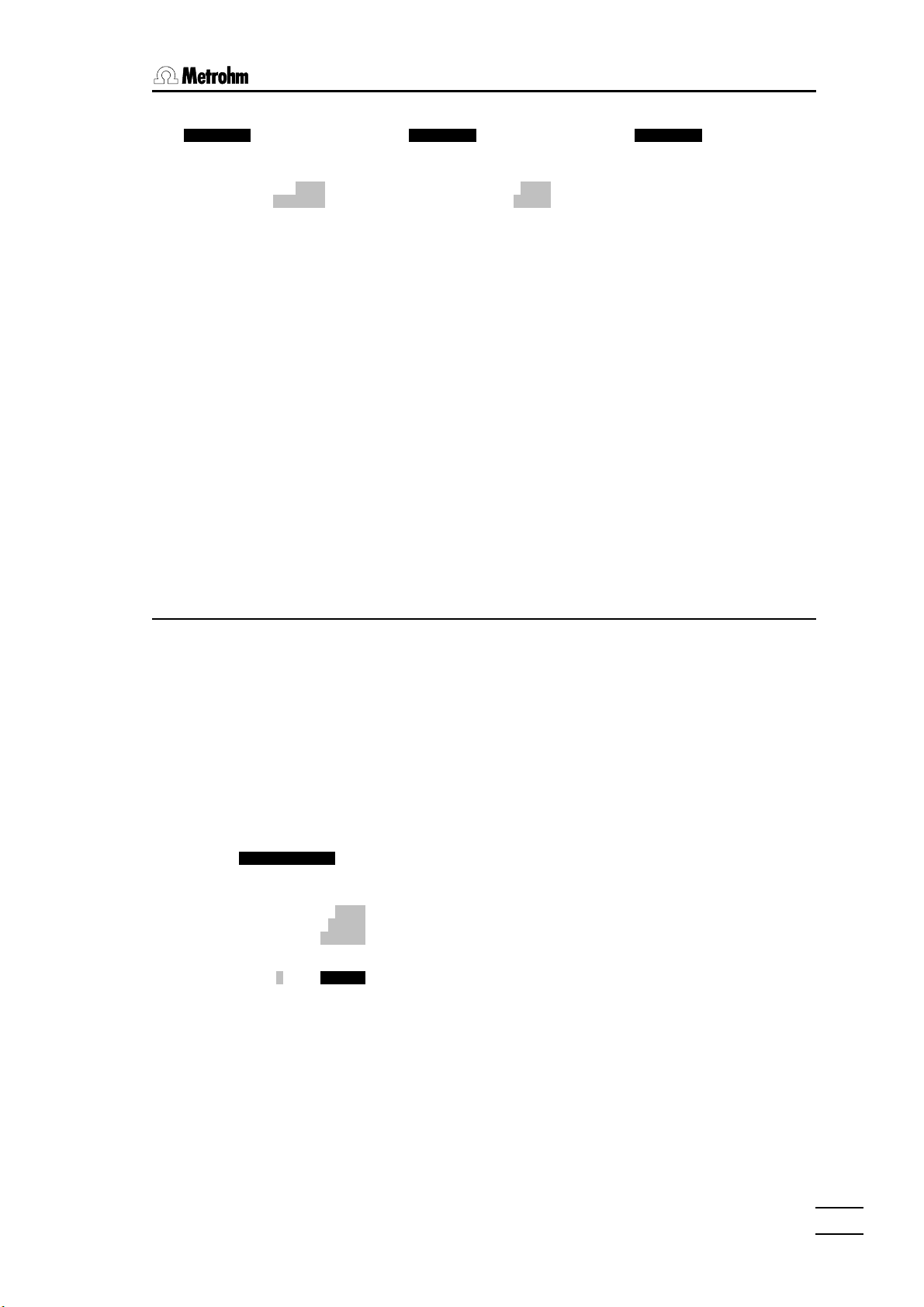
4. Manual operationManual operation
ÚÄÄÄ Messung ДДДДДДДДДДДДДД¿
³ ³
³ Meas. parameters A1 ³
³ ³
³ Meas. mode pH ³
³ Ref.temp. 25 §C ³
³ ³
³ ³
³ * pH 4.598 * ³
³ ³
³ ³
³ ³
³ ³
АДДДДДДДДДДДДДДДДДДД QUIT ДЩ
Depending on the selected measuring input the following measuring modes
can be used:
pH pH measurement, with temperature correction
U potential measurement in mV
Upol measurement of polarization current with preselected
Ipol measurement of polarization voltage with preselected
T temperature measurement with Pt100/1000
The [Start Stop] softkey starts the measurement or breaks it off again.
ÚÄÄÄ Messung ДДДДДДДДДДДДДД¿
³ ³
³ Meas. parameters Apol ³
³ ³
³ Meas. mode Upol ³
³ U(pol) 400 mV ³
³ ³
³ ³
³ * 5.34 жA * ³
³ ³
³ ³
³ ³
³ ³
АДДДДДДДДДДДДДДДДДДД QUIT ДЩ
polarization voltage
polarization current
ÚÄÄÄ Messung ДДДДДДДДДДДДДД¿
³ ³
³ Meas. parameters AT ³
³ ³
³ ³
³ ³
³ ³
³ ³
³ * 21.5 §C * ³
³ ³
³ ³
³ ³
³ ³
АДДДДДДДДДДДДДДДДДДД QUIT ДЩ
4.3.3 Calibration
ЪДДД Devices & Manual Control ДДДДДДДДДДДДДДДДДДДДДДДДДДДДДДДДДДДДДДДДДДДДДДДДД¿
³ ³
³ Dosing devices at interface A press <TAB> for more ³
³ ³
³ Dos. drive A1 700 A2 685 A3 --- A4 --- ³
³ Reagent AgNO3 HCl ³
³ Concentr. 0.01 mol/L 0.1 mol/L ³
³ Tubing Default Default Default Default ³
ГДДД Calibration ДДДДДДДДДДДДДДДДДДДДДДДДДДДДДДДДДДДДДДДДДДДДДДДДДДДДДДДДДДДДДД´
³ ³
³ Meas. parameters A1: # Buffer pH val. T[§C] pH cor. Val.[mV] ³
³ ДДДДДДДДДД ДДДДДДД ДДДДД ДДДДДДД ДДДДДДДД ³
³ Signal drift 2 mV/min 1 Metrohm 4.000 23.0 3.996 175.6 ³
³ Equilibr.time 110 s 2 Metrohm 7.000 23.0 7.008 0.9 ³
³ Temperature 23.0 §C ³
³ Buffer type Metrohm 4.00 ..9.00 ³
³ ³
³ Buffer 3 pH ³
³ ³
³ ³
³ ³
³ ³
АДДДДДДДДДДДДДДДДДДДДДДДДДДДДДДДДДДДДДДДДДДДДДДДДДДДДДДДДДДДДДДДДДДДДД QUIT ДДДЩ
АДДДДДДДДДДДДДДДДДДДДДДДДДДДДДДДДДДДДДДДДДДДДДДДДДДДДДДДДДДДДДДДДДДДДДДД QUIT ДЩ
ЪДДДДДДДВДДДДДДДВДДДДДДД¿ ЪДДДДДДДВДДДДДДДВДДДДДДД¿ ЪДДДДДДДВДДДДДДДВДДДДДДД¿
³Preset ³ Add ³ ³ ³ Start ³ ³ ³ ³Clear ³Cancel ³ Show ³
³series ³series ³ ³ ³ Stop ³ ³ ³ ³calibr.³calibr.³ curve ³
АДДДДДДДБДДДДДДДБДДДДДДДЩ АДДДДДДДБДДДДДДДБДДДДДДДЩ АДДДДДДДБДДДДДДДБДДДДДДДЩ
pH sensors at measuring inputs A1, A2, Adiff, B1, B2 and Bdiff can be
calibrated. The calibration data of the particular measuring input remain
unchanged until they are altered, even if the Titroprocessor is switched off.
The [Calibr.] softkey opens the calibration window.
726 Titroprocessor, Instructions for use
5757
Page 64

4.3 Sensors
The buffers required for the calibration of a pH sensor can be defined
individually or a predefined buffer series can be used. Many buffer solution
manufacturers offer complete buffer series. Calibration with two buffer
solutions (two-point calibration) is normally adequate.
Softkeys
[Preset
series] lists all the buffer solutions of the selected manufacturer
or type in the buffer table.
[Add
series] adds the whole list of buffer solutions of the selected
manufacturer or type to the existing buffer table.
[Start
Stop] starts or stops a measurement.
[Clear
calibr.] deletes the existing calibration or the calibration data. The
buffer table used for this can remain if the query shown
on deletion is answered with 'n'.
[Cancel
calibr.] breaks the started calibration off. The previous calibration
data are restored and the calibration window closed.
[Show
curve] shows the currently valid calibration curve, see example
below.
5858
As in titrations and measurements, the measuring parameters can be
individually selected for the sensor calibration.
726 Titroprocessor, Instructions for use
Page 65

4. Manual operationManual operation
Measuring parameters
Signal drift Limits for signal drift
0.5…2…999 mV/min | off
The measurement is only accepted if the measurement
change of the sensor falls below the preset value for the
signal drift. If this is delayed, the measurement will
nevertheless be accepted when the preset equilibration
time (see below) has elapsed.
This signal drift control can be switched off ('off').
However, this cannot be recommended for correct
calibration.
Equilibr.time Max. equilibration time before measurement
acceptance
0.1…9999 s | auto | off
The whole equilibration time for measurement
acceptance is only effective when, with drift control
switched on (see signal drift above), the preset value for
signal drift is not undercut. Otherwise the measurement
is accepted as soon as the preset signal drift is
achieved.
The whole equilibration time will also be allowed to
elapse if the drift control is switched off.
The equilibration time can be switched off. This means
that only the signal drift is decisive for measurement
acceptance.
In the setting ‘Equilibr.time auto' the
Titroprocessor will calculate an equilibration time suited
to the preset value for the signal drift according to the
following equation:
726 Titroprocessor, Instructions for use
Equilibr time in s
. ( )
drift mV
150
/ ( / min) ,=+
For the standard setting 2 mV this results in an
equilibration time of 110 s.
Temperature Temperature setting or measuring mode
-170…25.0…500°C | auto | off
The temperature can be determined during a
measurement with the help of a Pt100/Pt1000 sensor or
a combined electrode with built-in temperature sensor.
It is required for automatic pH correction.
numeric manual input
auto automatic measurement during the
calibration
off no temperature correction
0 01
+
5
5959
Page 66

4.3 Sensors
Buffer solutions
As buffer solutions can have very different compositions it is necessary to
give the correct buffer type so that the temperature correction is correctly
used for the calibration.
Select a buffer type or manufacturer. Insert a buffer series into the buffer
table by pressing the [Preset series] softkey or [Add series].
Calibration is also possible without a predefined buffer list. The buffer (type
and value) can be entered individually. Different types of buffer can also be
used. If your type of buffer is not contained in the selection list then select
'none'.
Enter the nominal value of your buffer solution in the line
Buffer 1 pH
and start a measurement with the [Start Stop] softkey.
During the calibration the values found are compared with the predefined
values of the buffer solutions (theoretical value, temperature with automatic
temperature measurement) and subjected to a plausibility test, see page
117. If this should cause annoying error messages with 'exotic’ buffers or
'unusual’ sensors then select buffer type 'custom' for user-defined buffer
types. No plausibility tests are carried out in this setting.
After each buffer solution measurement the calibration values are entered in
the buffer table.
# Buffer pH val. T[§C] pH cor. Val.[mV]
ДДДДДДДДДД ДДДДДДД ДДДДД ДДДДДДД ДДДДДДДД
1 Metrohm 4.000 23.0 3.996 175.6
2 Metrohm 7.000 23.0 7.008 0.9
The buffer table includes the following data:
• buffer type or manufacturer
• nominal pH
• buffer temperature
• (temperature)-corrected effective pH
• measured potential in mV
When a measurement has been completed the next buffer solution can be
entered and measured.
After at least two measurements have been made the calibration curve can
be displayed by pressing the [Show curve] softkey. The corresponding
values for the slope and the asymmetry pH (pHas ) are shown together with
the calibration curve.
6060
726 Titroprocessor, Instructions for use
Page 67

4. Manual operationManual operation
Calibration data are allocated to a measuring input (e.g. A1) and stored in
the Titroprocessor. The calibration data can be checked at any time. Before
a sensor is recalibrated the previous calibration must be deleted with the
[Clear calibr.] softkey.
Calibration data and calibration interval
³ Sensors at interface A
³
³ Meas. input A1 A2
³ Sensor 6.0203.100 6.0232.100
³ Cal. sensor comb. glass 6.0232.100
³ Cal. method * by edit * manual
³ Cal. date 97-12-15 15:46 97-12-10 14:37
³ Next Calibr. 97-12-14 08:00
³ pH(as) 7.000 6.987
³ Slope 1.000 0.996
The 'Manual control page' always shows the calibration data for each
measuring input with the name of the calibrated sensor, the calibration
method (calibrations can be carried out automatically by a determination or
as part of a series of samples) as well as the date and time of the
calibration. The time for the next calibration can be set additionally. An
appropriate warning is displayed when this time has been reached. The
calibration interval defined in this way is reset at each subsequent
calibration, i.e. the time for the next calibration is automatically calculated.
The calibration data pHas and slope can – if necessary – be manually
altered. Previous calibrations will be overwritten.
Further information about calibration can be found on page 116f.
726 Titroprocessor, Instructions for use
6161
Page 68

4.4 Sample changer
4.4 Sample changer
One or two sample changers (if connected) can be operated from the
sample changer window which is accessed with the [Sample changer]
softkey on the ‘Manual control page’.
ЪДДД Devices & Manual Control ДДДДДДДДДДДДДДДДДДДДДДДДДДДДДДДДДДДДДДДДДДДДДДДДД¿
³ ЪДДД Sample changer ДДДДДДДДДДДДДДДДДДДДДДДДДДДДДДДДДДДДДДДДДДДДДДДДДДДД¿ ³
³ Do³ ³ ³
³ ³ Changer 1: ready [000001] 2: not available ³ ³
³ Do³ ДДДДДДДДДДДДДДДДДДДДДДДД ДДДДДДДДДДДДДДДДДДДДДДДД ³ ³
³ Re³ Rack type/name M12-0 - 12*250mL ³ ³
³ Ko³ Max. beakers 12 ³ ³
³ Bь³ ЪДДДДДДДДДДД¿ ³ ³
³ Bü³ Tower ³ 1 ³ 2 ³ ³
³ Ko³ Lift pos.[mm] ³ 0 ³ 0 ³ ³
³ Do³ Beaker pos. ³ 1 ³ 12 ³ ³
³ÄÄij Beaker found ³ yes ³ no ³ ³
³ Se³ ³ ³ ³ ³
³ ³ Pumps ³rinse aspir³ rinse aspir ³ ³
³ Me³ ³ off off ³ off off ³ ³
³ Se³ АДДДДДДДДДДДЩ ³ ³
³ Ka³ Stirrer 1 2 3 4 ³ ³
³ Ka³ off off off off ³ ³
³ Ka³ Stirring rate 3 3 3 3 ³ ³
³ Nд³ ДДДДДДДДДДДДДДДДДДДДДДДДДДДДДДДДДДДДДДДДДДДДДДДДДДДДДДДДДДДДДДДДДДДД ³ ³
³ pH³ <PG UP> lift to shift position ³ ³
³ St³ <PG DN> lift to work position; <HOME> lift to rest position ³ ³
³ АДДДДДДДДДДДДДДДДДДДДДДДДДДДДДДДДДДДДДДДДДДДДДДДДДДДДДДДДДДДДДДДДД QUIT ДЩ ³
АДДДДДДДДДДДДДДДДДДДДДДДДДДДДДДДДДДДДДДДДДДДДДДДДДДДДДДДДДДДДДДДДДДДДДДД QUIT ДЩ
ЪДДДДДДДВДДДДДДДВДДДДДДД¿ ЪДДДДДДДВДДДДДДДВДДДДДДД¿ ЪДДДДДДДВДДДДДДДВДДДДДДД¿
³Reset ³Remote ³Stirrer³ ³Pump ³ Lift ³ Lift ³ ³Shift ³Shift ³Shift ³
³changer³lines ³on/off ³ ³on/off ³ up ³ down ³ ³left ³right ³to pos.³
АДДДДДДДБДДДДДДДБДДДДДДДЩ АДДДДДДДБДДДДДДДБДДДДДДДЩ АДДДДДДДБДДДДДДДБДДДДДДДЩ
read-in rack
code
selection frame (marks
the selected tower)
field cursor (marks the
selected stirrer or the
selected pump
2nd changer not
connected
rack data
The sample changer window shows the status of the connected sample
changers. The softkey bar allows the components of each sample changer
to be operated.
For each connected sample changer the data of the sample rack placed on
it are shown, i.e. sample rack type, rack code and number of beaker
positions.
The following status information is provided for each tower: lift position,
current beaker position and the result of the automatic beaker test (whether
a beaker is present or not).
The current status of each pump (rinsing or aspiration pump) and each
stirrer is shown together with the stirrer speed which can be set in 15 steps.
The stirrer speed can be entered directly in the particular entry field
selected.
The cursor keys <ç> and <è> (or <TAB>) can be used to select a
tower, pump or stirrer. A frame shows the selected changer and tower for
which a function can be triggered with a softkey. The field cursor (black
background) shows the particular stirrer selected or pump selected.
6262
726 Titroprocessor, Instructions for use
Page 69

4. Manual operationManual operation
Softkeys
[Reset
changer] initializes the sample changer. When a sample rack has
been exchanged it is necessary to initialize the sample
changer. In this process all lifts are moved to the rest
position, the sample turntable is rotated to the initial
position and the magnet code is read to identify the new
rack.
[Remote
lines] opens the dialog window of the remote-lines of the
selected sample changer. The conditions of the logical
input lines can be seen and the conditions of the output
lines can be set.
ÚÄÄÄ Remote lines: 1 ДДДДДД¿
³ ³
³ I/O lines 32109876543210 ³
³ ДДДДДДДДДДДДДДДДДДДДДДДД ³
³ Input 00000001 ³
³ Output **********0001 ³
³ ³
АДДДДДДДДДДДДДДДДДДД QUIT ДЩ
The output lines can be set individually (1) or reset (0).
Lines which are not to be altered can be given an '*'.
Further details can be found on pages 200f and 29f.
[Stirrer
on/off] switches the selected stirrer on or off.
[Pump
on/off] switches the selected pump on or off.
[Lift up] moves the lift of the selected tower upwards. This is only
possible if the sample rack is aligned to the tower. With
sample racks which are not expressly designed for twotower operation e.g. 14-place or 16-place racks, the rack
should first be rotated to the left or right by one position,
see softkeys below.
[Lift
down] moves the lift of the selected tower downwards. Please
note the remarks about the previous softkey.
[Shift
left] rotates the sample rack of the selected changer
counterclockwise by one position. The lifts of the changer
must be in the shift position or a higher position.
[Shift
right] rotates the sample rack of the selected changer
clockwise by one position. The lifts of the changer must
be in the shift position or a higher position.
[Shift
to pos.] opens the dialog window for targeted positioning of
sample racks, see below.
726 Titroprocessor, Instructions for use
6363
Page 70

4.4 Sample changer
4.4.1 Sample rack and lift functions
For safety reasons it is not possible to rotate a sample rack if a lift is in a
lower position than the specified shift position. This is why it is important to
determine the correct sample rack definitions with great care (see page 37).
Press the <PG UP> key or <HOME> before the sample rack is to be
rotated.
If a sample rack is used which has not been designed for parallel
processing with a two-tower changer model (M14-0, M16-0, M19-0 …) then
a rack position must be correctly aligned in front of the particular tower so
that the lift can be operated. This is done by marking the target tower and
then rotating the sample rack to the left or right with the corresponding
softkeys.
Move lift
The <PG UP> and <PG DN> keys bring the selected lift to the shift or
working positions which are defined in the rack definitions of the mounted
sample rack. The <HOME> key brings the lift to the rest position (0 mm
position) at the topmost position of the selected tower. In order to move a lift
millimeter by millimeter the [Lift up] and [Lift down] softkeys
should be used.
Move beaker to absolute position
As well as the possibility of rotating the rack by one position (softkeys
[Shift left] and [Shift right]) a particular beaker position which
is to be placed in front of a tower by a rack rotation can be entered. Press
the [Shift to pos.] softkey to carry this out
ÚÄÄÄ Move beaker absolute ДДДДД¿ ³ ³
³ ³ ³ ³
³ Changer 1 ³ ³ ³
³ ³ ³ ³
³ Move beaker 1 ³ ³ ³
³ to tower 1 ³ ³ ³
³ ³ ³ ³
АДДДДДДДДДДДДДДДДДДДДДДД QUIT ДЩ ³ ³
ДДДДДДДДДДДДДДДДДДДДДДДДДДДДДДДДДДДД QUIT ДЩ ³
ДДДДДДДДДДДДДДДДДДДДДДДДДДДДДДДДДДДДДД QUIT ДЩ
ДВДДДДДДДВДДДДДДД¿ ЪДДДДДДДВДДДДДДДВДДДДДДД¿
³ ³ ³ ³Shift ³Shift ³Shift ³
³ ³ ³ ³left ³right ³auto ³
ДБДДДДДДДБДДДДДДДЩ АДДДДДДДБДДДДДДДБДДДДДДДЩ
Which beaker is to be positioned in front of which tower can be entered
here. Press a softkey to rotate the rack in the corresponding direction.
[Shift
left] rotates the rack counterclockwise.
6464
[Shift
right] rotates the rack clockwise.
726 Titroprocessor, Instructions for use
Page 71

[Shift
auto] rotates the rack automatically. The shortest rotary path is
selected.
4.5 Stirrer at measuring interface
Each measuring group of the Titroprocessor 726 is equipped with a stirrer
connection (12 V) to which various stirrers can be connected. These
include:
• 728 Magnetic stirrer 2.728.0040
• 722 Rod stirrer 2.722.0010
• 727 Ti-Stand with rod stirrer 2.727.0010
• 727 Ti-Stand with magnetic stirrer 2.727.0100
• 703 Ti-Stand 2.703.0010
The stirrer connection of a measuring group (see rear view of instrument,
page 4) is switched on as standard. It can be switched on the 'Manual
control page' (<MAN CONTROL> key) with the [Stirrer on/off]
softkey. If necessary select the first measuring group ('Sensors at
interface A/B') with the <PG DN> and <TAB> keys.
4. Manual operationManual operation
The status of the stirrer connection is always shown at the bottom right-hand
side.
Apol ³
³
³
7.000 Stirrer on ³
1.000 ³
³
ДДДДДДДДДДДДДДДДДДДДДДДД QUIT ДЩ
ДДД¿ ЪДДДДДДДВДДДДДДДВДДДДДДД¿
³ ³ ³Stirrer³Remote ³
³ ³ ³on/off ³lines ³
ДДДЩ АДДДДДДДБДДДДДДДБДДДДДДДЩ
4.6 Remote lines (Input / Output)
The [Remote lines] softkey on the 'Manual control page'
(<MAN CONTROL> key) opens the dialog window of the remote
connection of the Titroprocessor 726.
ÚÄÄÄ Leitungen: A ДДДДДДДДД¿
³ ³
³ I/O Status 76543210 ³
³ ДДДДДДДДДДДДДДДДДДДДДДДД ³
³ Input 00000001 ³
³ Output ****0001 ³
³ ³
АДДДДДДДДДДДДДДДДДДД QUIT ДЩ
4.7 Print
726 Titroprocessor, Instructions for use
Here the conditions of the logical input lines can be seen and the
conditions of the output lines can be set.
The output lines can be set individually (1) or reset (0). Lines which are not
to be altered can be given an '*'. Further details can be found on pages 200f
and 29f.
The built-in A4 thermal printer or any other printer which has been
connected and configured can be operated with the yellow printing keys.
6565
Page 72

4.7 Print
STOP FORM
PRINT
The <PRINT> key opens the printer menu from which any type of report can
be selected. Global reports and determination reports (if a determination is
present in the working memory) can be selected.
<ññ><PRINT> (= STOP PRINT) interrupts a printout immediately.
<LINE FEED> causes a line feed if a printer is connected.
<ññ><LINE FEED> (= FORM FEED) causes a page feed if a printer is
connected. With page-oriented printers like laser printers and inkjet printers
this key is used to eject the page .
<PRINT SCREEN> prints the current screen contents. This is always
printed out on the built-in thermal printer or another printer connected to the
parallel 'Printer' port.
4.7.1 The printer menu
FEED
LINE
PRINT
SCREEN
The <PRINT>key calls up the printer menu.
ÚÄÄÄ Print Determ.report ДДДДДДДДДДДДДДДДДДДДДДДДДДДДДДДДДДДД¿
³ ³
³ Determination : 97121610.004 ³
³ ³
³ ShrtRes ³
³ FullRes ³
³ Sample data ³
³ Common Variables (local) ³
³ # 1 DET_PH* Titration of free acid ³
³ all determination reports ³
³ ³
³ ³
³ ³
³ ³
³ ³
АДДДДДДДДДДДДДДДДДДДДДДДДДДДДДДДДДДДДДДДДДДДДДДДДДДДДД QUIT ДЩ
ЪДДДДДДДВДДДДДДДВДДДДДДД¿ ЪДДДДДДДВДДДДДДДВДДДДДДД¿ ЪДДДДДДДВДДДДДДДВДДДДДДД¿
³Select ³Select ³ ³ ³Global ³ ³ ³ ³ Print ³ Send ³ Print ³
³determ.³report ³ ³ ³Reports³ ³ ³ ³ Send ³ ³ ³
АДДДДДДДБДДДДДДДБДДДДДДДЩ АДДДДДДДБДДДДДДДБДДДДДДДЩ АДДДДДДДБДДДДДДДБДДДДДДДЩ
The printer menu shows the possible reports for the current determination. A
report can be selected with the cursor keys <êê> and <éé> and the
corresponding softkey can be used to print it out.
6666
726 Titroprocessor, Instructions for use
Page 73

4. Manual operationManual operation
Softkeys
[Select
determ.] opens a selection list of the determinations in the working
memory. A different determinationfor printing out reports
can be selected.
[Select
report] if a titration or measurement within a determination has
been selected then this softkey opens the selection list
containing possible report modes , see below.
[Global
Reports] opens the dialog window for selection of the global
reports, see below.
ÚÄÄÄ Print Determ.report ДДДДДДДДДДДДДДДДДДДДДДДДДДДДДДДДДДДД¿
³ ЪДДД Print Global reports ДДДДДДДДД¿ ³
³ ³ ³ ³
³ ³ Configuration ³ ³
³ ³ Data card ³ ³
³ ³ Internal Storage ³ ³
³ ³ Commands ³ ³
³ ³ Method ³ ³
³ ³ Sample Silo ³ ³
³ ³ Devices & Manual Control ³ ³
³ ³ Common Variables ³ ³
³ ³ Full statistics ³ ³
³ ³ Short statistics ³ ³
³ ³ GLP ³ ³
³ АДДДДДДДДДДДДДДДДДДДДДДДДДДД QUIT ДЩ ³
АДДДДДДДДДДДДДДДДДДДДДДДДДДДДДДДДДДДДДДДДДДДДДДДДДДДДД QUIT ДЩ
[Send] starts the output of the selected report to the
[Print] starts the output of the selected report at the configured
4.7.2 General reports
General reports are not dependent on a determination. They present the
momentary settings effective on the instrument.
Configuration Report of the settings in the configuration window and its
Data card List of stored files on the data card
Internal
storage List of stored files in the internal memory
Commands List of command sequences of the current method,
Method Comprehensive listing of the current method , including
communication interface. The report is transferred to the
instrument (e.g. a personal computer) which is connected
to the defined RS232 interface.
printer.
sub-windows
without parameters
application remarks, command sequences and all their
parameters.
726 Titroprocessor, Instructions for use
Sample Silo List of all sample data in the sample silo
6767
Page 74

4.7 Print
Devices & Manual
Control Report of the current settings on the 'Manual control
Common
Variables List of the global common variables
Full statistics Comprehensive statistical report
Short statistics Report of the statistical results
GLP Report of the GLP results
4.7.3 Determination reports
Use the [Select determ.] softkey to select a determination from the
selection list in the working memory. Any alterations which may have been
carried out to the settings or re-evaluations of the determination data are
taken into account in reports printed out manually.
ShrtRes Short result report of all results of the determination
FullRes Comprehensive result report of the results of the
page'
determination
Sample data Report of the sample data used in the determination
Common
Variables (local) List of the common variables stored with the
determination
all
determination reports
All the reports defined in the determination are
printed out
All titrations and measurements in a determination are also listed in the
printer menu, e.g.
# 1 MEAS_PH* pH measurement
# 2 DET_pH* Titration of free acid
If one of these lines is selected then after the [Select report] softkey is
pressed then a report can be printed out of one of the mode reports of this
titration or measurement. All reports of the corresponding mode are
possible.
6868
726 Titroprocessor, Instructions for use
Page 75

4. Manual operationManual operation
ÚÄÄÄ Print Determ.report ДДДДДДДДДДДДДДДДДДДДДДДДДДДДДДДДДДДД¿
³ ³
³ Determination : 97121011.011 ³
³ ³
³ ЪДДДДДДДДДД¿ ³
³ ³C_Curve >³ ³
³ ³V_Curve >³ ³
³ ³T_Curve ЪДДДДДДДДДДД¿ ³
³ ³*Stand ³M. value >³ ³
³ ³*FullRes ³Volume ЪДДДДД¿ ³
³ ³*ShrtRes ³Temp. ³print³ ³
³ ³SmplData ³dMV/dV ³send ³ ³
³ ³CalData ³dMV/dt АДДДДДЩ ³
³ ³*Param ³dV/dt >³ ³
³ ³MP_List ³MV,Temp. >³ ³
АД³Calc ³MV,dMV/dV >³ДДДДДДДДДДДДДДДДДДДДДДДДДДДДД QUIT ДЩ
³RawData ³all >³
³FormFeed АДДДДДДДДДДДЩ
³FullStat >³
³ShrtStat >³
АДДДДДДДДДДЩ
Details of the individual reports can be found on page 123ff.
726 Titroprocessor, Instructions for use
6969
Page 76

5.1 General
5 Methods and determinations
5.1 General
A method must be loaded in the working memory in order to carry out a
determination on a sample. The creation of a method for each application is
recommended; this should be stored in the internal memory or on a data
card so that it can be loaded and used whenever required.
A method consists of a sequence of different commands which are carried
out when a sample is processed. The commands may be titration mode
commands, measuring mode commands, sample changer commands or
other commands. Up to five titration or measuring modes can be contained
in one method. A total of 99 commands can be carried out in sequence.
The easiest way of loading methods is with the <METHOD> key. This is
also possible in the method editor via the [File] softkey or in the file
manager with the key sequence [Copy to] 'Working memory'. If the
Auto start function is used methods can also be loaded automatically from
the sample silo.
If a sample changer is used (Auto start ‘on’) then a start sequence
and/or a closing sequence can be defined. A start sequence(OMOVE ...
)OMOVE is carried out with the first sample of a series. A closing
sequence(CMOVE ... )CMOVE is carried out with the last sample of a
series.
Line time
Command
lines
Conditional command sequences (CASE structures) can be defined; these
are only carried out when a particular condition has been fulfilled.
5.2 Method editor
The method editor is called up from the main page by pressing the [Edit
method] softkey.
ЪДДДД Method : HCl.mth ДДДДДДДДДДДДДДДДДДДДДДДДДДДДДДДДДДДДДДДДДДДДДДДДДДДДДДДД¿
³ ³
³ t/s Command Parameters Parameters ³
³ ДДДДД ДДДДДДДДДДДДД ДДДДДДДДДДДДДДДДДДДДДДДД ДДДДДДДДДДДДДДДДДДДДДДДД ³
³ 1! ASK Ident. item none Size yes ³
³ 2 30 STIR_I Meas.interface A State on ³
³ 3 DET_PH* Titer determination ³
³ Reagent HCl Sensor 6.0232.100 ³
³ Concentr. 0.1 mol/L Meas. input A1 ³
³ Dos. drive A1 ³
³ 4 STIR_I Meas.interface A State off ³
³ 5 END ³
³ ³
³ ³
³ ³
³ ³
³ ³
³ ³
Load and store
³ ³
methods
³ ³
Application
³ ³
³ ³
notes
³ ³
АДДДДДДДДДДДДДДДДДДДДДДДДДДДДДДДДДДДДДДДДДДДДДДДДДДДДДДДДДДДДДДДДДДДДДДД Quit ДЩ
ЪДДДДДДДДДДДДДДДДДДДДДДД¿ ЪДДДДДДДДДДДДДДДДДДДДДДД¿ ЪДДДДДДДДДДДДДДДДДДДДДДД¿
³ Note ³ File ³Determ.³ ³ * ³ * ³ * ³ ³Insert ³Delete ³ >> ³
³ ³ ³report ³ ³ Param ³Formula³ Report³ ³line ³line ³ >> ³
АДДДДДДДДДДДДДДДДДДДДДДДЩ АДДДДДДДДДДДДДДДДДДДДДДДЩ АДДДДДДДДДДДДДДДДДДДДДДДЩ
Method name
Parameters
Report definitions for
whole determinations
Editing functions
7070
726 Titroprocessor, Instructions for use
Page 77

5. Methods and determinations
5.2.1 Load method
The [File] softkey is pressed in order to load an existing method; this
opens the file dialog window.
File dialog window
Check whether the memory area from which the method is to be loaded has
been correctly set. If this is the case then press the space bar to display the
list of existing methods. The field cursor must be in the 'Name' field. Use the
cursor to select a method and confirm with <ENTER>.
ЪДДДДДДДДДДДДДДДДДДДДДДДДДДДДДДДДДДДДДДДДДДДДДДДДДДДДДДДДДДДД¿
³NaOH :Titer of NaOH ³
³HCl :Titer of HCl ³
³GLP :Titer of HCl (validation method) ³
³CaMgTap :Calcium / Magnesium in Tap Water ³
³Chloride :Chloride in Tap Water ³
³Metals :Complexometric Titration of Metals with Cu++ ISE ³
³Fe3_back :Complexom. back titration of Fe(III) with Cu++ ISE³
³Anionic :Anionic Surfactants in Shampoo ³
³Cationic :Cationic Surfactants in Fabric Softener ³
³Formol :Formaldehyde Number in Fruit Juices ³
³Peroxide :Peroxide Number ³
³TAN :Total Acid Number (TAN) ³
³TBN :Total Base Number (TBN) ³
ÚÄÄÄ Files ДД³Diazo :Diazotisation titration of 2ДAminophenol ³
³ АДДДДДДДДДДДДДДДДДДДДДДДДДДДДДДДДДДДДДДДДДДДДДДДДДДДДДДДДДДДДЩ
³ Name HCl .mth ³
³ Comment Titer of HCl ³
³ Storage Data card ³
³ ³
АДДДДДДДДДДДДДДДДДДДДДДДДДДДДДДДДДДДДДДДДДДДДДДДДДДДДДДДДДДДД QUIT ДЩ
A selection of the methods which can be found on the application card
supplied with the Titroprocessor 726 is shown above.
If the required method is to be found in a different memory area from that
set then select this memory area in the way described above, but this time
in the 'Storage' field. The internal memory, a data card or the two RS232
interfaces can be selected. The way in which methods can be read in
directly from a PC via the RS232 interfaces is described in section 11 File
manager (page 225ff).
5.2.2 Create new method
In the method editor a new method is created by pressing the [File] key
in order to open the file dialog window. Now press the [New] softkey.
An 'empty' method appears with an empty line and a line with the 'END'
command. A method must always be concluded with the ‘END’ command,
so do not delete this line.
726 Titroprocessor, Instructions for use
7171
Page 78

5.2 Method editor
In order to define the command sequence enter the required command in
the command column manually (the first letters are sufficient) or select a
command from the nested selection list.
³ t/s Command Parameters
³ ДДДДД ДДДДДДДДДДДДД ДДДДДДДДДДДДДДДДДДДДДДДД
³ 1
³ 2 END ЪДДДДДДДДДДД¿
³ ³Titration >Titration >³
³ ³Changer ЪДДДДДДД¿
³ ³CAL ³DET_* >DET_* >³
³ ³MEAS_* ³MET_* ЪДДДДДДДДД¿
³ ³DOS ³SET_* ³DET_PH* DET_PH*
³ ³STIR_I ³SEC_* ³DET_U* ³
³ ³CASE ³KFT_* ³DET_UPOL*³
³ ³COMM ³KFC_* ³DET_IPOL*³
³ ³AUX АДДДДДДБДДДДДДДДДЩ
³ АДДДДДДДДДДДЩ
When the command has been accepted with <ENTER> the parameters of
the selected command are shown and can now be edited. The titration and
measuring modes (all *commands) have extended sets of parameters.
These can be accessed via the [* ...] softkeys. If a command marked
with an asterisk is marked with the cursor in the command column then the
[* Param] [*Formula] [*Report] softkeys are activated. In this way
the further settings which only apply to this particular command or mode
can be edited.
ЪДДД Method : HCl.mth ДДДДДДДДДДДДДДДДДДДДДДДДДДДДДДДДДДДДДДДДДДДДДДДДДДДДДДДДД¿
³ ³
³ t/s Command Parameters Parameters ³
³ ДДДДД ДДДДДДДДДДДДД ДДДДДДДДДДДДДДДДДДДДДДДД ДДДДДДДДДДДДДДДДДДДДДДДД ³
³ 1! MEAS_PH* pH measurement ³
³ Sensor 6.0232.100 Signal drift 50 mV/min ³
Measuring
³ Meas. input A1 Equilibr.time auto s ³
³ Temperature 25.0 øC ³
mode
³ 2 180 DET_PH* Dynamic equivalence point titration ³
³ Reagent HCl Sensor 6.0232.100 ³
³ Concentr. 0.1 mol/L Meas. input A1 ³
Titration
³ Dos. drive A1 ³
mode
³ 3 END ³
³ ³
³ ³
³ ³
³ ³
³ ³
³ ³
³ ³
³ ³
³ ³
³ ³
АДДДДДДДДДДДДДДДДДДДДДДДДДДДДДДДДДДДДДДДДДДДДДДДДДДДДДДДДДДДДДДДДДДДДДДД Quit ДЩ
ЪДДДДДДДВДДДДДДДВДДДДДДД¿ ЪДДДДДДДВДДДДДДДВДДДДДДД¿ ЪДДДДДДДВДДДДДДДВДДДДДДД¿
³ Note ³ File ³Determ.³ ³ * ³ * ³ * ³ ³Insert ³Delete ³ >> ³
³ ³ ³report ³ ³ Param ³Formula³ Report³ ³line ³line ³ >> ³
АДДДДДДДБДДДДДДДБДДДДДДДЩ АДДДДДДДБДДДДДДДБДДДДДДДЩ АДДДДДДДБДДДДДДДБДДДДДДДЩ
Mode-specific settings
Allocation parameters
A command line consists of a line number with the line attribute, the line
time, a command name and the parameters.
With a ’!’ sign as line attribute the execution of a line can be suppressed (if
required); see line 1 above. A block of lines to be suppressed can be
marked with an ‘@’ sign in the first and last lines. This possibility can be very
useful when a newly created method is being tested.
A line time (see line 2 above) can be entered as an option; this sets a
minimum time in which a command must be carried out. The next
7272
726 Titroprocessor, Instructions for use
Page 79

command will not be carried out until this time has elapsed and the
command involved has been carried out completely.
The functions and parameters of the individual commands are described in
detail in section 8. Command references (page 127ff).
A method is stored in the file dialog window (see page 71) with the [Save]
softkey. The method name, storage area and an optional method
commentary can be freely selected.
5.2.3 Softkeys and their functions
[Note] edits the application note which appears on the main
page. A short description of the current method or of the
sample preparation method can be entered. In the
application note edit window. The [Delete line],
[Blank line] [Copy line] [Paste line]
softkeys are available for comfortable text editing.
[File] The basic file operations are available in the file dialog
window (see page 71).
The name of a file can be freely selected or chosen from
the selection list of the selected storage area by pressing
the space bar. If files are to be saved on a computer
system then file names should be selected which the file
system of the computer can read. Avoid special
characters. Mixed capitals and lower case letters are
accepted by the Titroprocessor 726; however, this may
cause problems with other file systems.
Each file can be provided with a comment of max. 50
characters which appears in the selection list of the file
dialog window and in the file manager.
The selection of the memory area can also be made via a
selection list. A file can be transmitted or received via an
RS232 interface. These special functions are described in
the file manager section.
5. Methods and determinations
726 Titroprocessor, Instructions for use
[Determ. In addition to or instead of the mode report of titrations
report] or measurements a report of a complete determination
can be defined. This is particularly recommended when
several titration or measuring modes have been
programmed in a single method. Determination reports
form introductory and concluding report blocks as part of
the complete report. Between these the individual mode
reports (see [*Report] softkey below) are listed.
Detailed descriptions of the definition of determination
reports are given below.
7373
Page 80

5.2 Method editor
[* Param] Titration and measuring modes have extended sets of
parameters for setting control parameters, etc. These are
accessed via this softkey. Descriptions of each setting
can be found under command references, page 127ff.
[*Formula] Titration and measuring modes allow different calculation
formulas valid for the particular mode to be used. The
formula editor is described in section 7.10 (Titration and
measuring modes), page 118ff.
[* Report] Titration and measuring modes can contain various report
blocks which only apply to that particular mode. These
mode reports form individual parts of the full report and
appear between the introductory (start) determination
report and the concluding (end) determination report. A
description of the report editor is given in section 7.11
(Titration and measuring modes), page 123ff.
[Insert
line] inserts an empty command line in front of the current line.
[Delete deletes the current command line. The field cursor must
line] be in the command column.
[ >> >>] shows the second softkey bar.
[Copy copies the current command line in into a local
line] buffer.
[Cut copies the marked command into a local buffer
line] and deletes the current command line.
[Paste takes the copied command from the local buffer
line] and inserts it in front of the current command line.
[ >> >>] shows the first softkey bar.
5.2.4 Determination report
Determination report blocks can be defined as parts of the full report; they
can either be produced at the start of a determination or at the end of a
determination. In addition, reports can be defined which are produced at the
end of a determination when the capacity of the statistics counter is
reached.
Determination reports cannot only be printed out but can also be transferred
directly to a PC database such as the Metrohm software VESUV 3.
7474
726 Titroprocessor, Instructions for use
Page 81

5. Methods and determinations
The definition of the determination report is made in the report window of the
method editor after pressing the [Determ. report]softkey.
ÚÄÄÄ Determ.report ДДДДДДДДДДДДДДДДДДДДДДДДДДДДДДДДДДДДДДДДДДДДДДДДДДДДД¿
³ ³
³ initial print send FF final print send FF ³
³ ДДДДДДДД ДДДДД ДДДД ДДДД ДДДДДДДДД ДДДДД ДДДД ДДДД ³
³ Determination Commands yes no no FullRes yes no no ³
³ reports no no no SmplData yes no no ³
³ no no no no no no ³
³ no no no no no no ³
³ ³
³ Reports to be FullStat yes no no ³
³ printed on no no no ³
³ full statistics no no no ³
³ counter no no no ³
³ ³
³ Print signature line yes ³
³ Final form feed yes ³
³ ³
АДДДДДДДДДДДДДДДДДДДДДДДДДДДДДДДДДДДДДДДДДДДДДДДДДДДДДДДДДДДДДДДД QUIT ДЩ
The reports are printed out in the defined sequence. The report blocks
defined in the 'initial' column are printed out at the start of the determination,
those in the 'final' column when the determination is finished. In the lower
half of the edit window the reports which depend on the status of statistics
function are defined. These are only produced when the statistics counter is
full.
Type Type of report
at start: Commands | ComnVars | FormFeed
At the start of a determination reports can be produced
which contain the data or settings which are used in the
determination.
Commands commands in the method (without *Param)
ComnVars current common variables at start
FormFeed page feed at printer
Type Type of report
at end: Standard | FullRes | ShrtRes
SmplData | ComnVars | Commands
FormFeed | FullStat | ShrtStat
At the end of the determination reports are produced
which contain the data obtained during the determination.
If several modes have been carried out then the reports
include the data of all modes.
Standard standard report
FullRes full results report, detailed
ShrtRes short results report, minimal
SmplData sample data with sample weight
ComnVars common variables at start
Commands commands in the method (without *Param)
FormFeed page feed at printer
FullStat full statistical data report
ShrtStat short statistical data report
726 Titroprocessor, Instructions for use
7575
Page 82

5.2 Method editor
print Report printout
yes | no
With 'yes' a report will be printed out on all printers defined
in the configuration. This could be both the internal printer
as well as an external printer connected to the 'Printer'
connection or an RS232 interface.
send Report output via an RS232 interface
yes | no
A report can be transferred directly to a personal
computer via an RS232 interface. The particular RS232
interface to which the receiving instrument is connected
must have been defined as being the communication
interface in the interface configuration and the data
transfer mode 'LIMS' must be switched on. Take care that
the transmission parameters (baud rate, etc.) of the
receiving instrument are set to the same values as on the
Titroprocessor 726.
FF Page feed (form feed) at printer
yes | no
For formatting the printout of several report blocks it is
possible to provide each individual report with a following
page feed. A 'Form Feed' only affects the printer. Please
note that the internal thermal printer will only carry out a
form feed if 'Enable auto FF' is switched on in the
configuration of the interfaces.
Print signature line Operator name and signature line
yes | no
A signature line with the operator’s name can be printed
out at the end of the complete report.
Final form feed Page feed after last report line
yes | no
If reports are to be printed out on a page-oriented external
printer (inkjet printer, laser printer) then a form feed must
be carried out after the last report in order for the final
page to be ejected.
7676
726 Titroprocessor, Instructions for use
Page 83

5. Methods and determinations
Note:
A method is always edited directly in the working memory.
• It is possible to alter command parameters (including titration and
measuring modes) while a determination is being carried out. The
Titroprocessor 726 will try to use the altered settings as soon as
possible. Alterations to the parameters of a command which is not
currently being carried out will be taken into account during the same
method run. If titration or measuring modes are being carried out this
depends on the parameters which are altered.
Live-Parameter
In principle virtually all settings can be altered 'live'. Exceptions to this
include the allocation parameters (measuring inputs, dosing devices),
parameters which directly influence the volume increments or the
inclusion of additional measured quantities in the measuring point list (or
their elimination).
• The command sequence itself cannot be altered 'live', i.e. no new
commands can be inserted while a determination is being carried out,
nor can existing commands be deleted or altered.
• During a series of samples a new method can be loaded into the
working memory automatically by means of an appropriate entry in the
sample silo. However, this is not possible if alterations are being carried
out in the method editor at the same time, as the same memory areas
are used as are being overwritten by the new method. Avoid editing
methods when a series of samples is being processed.
• During the production of a determination report the method name is
mentioned in the header together with an attribute which informs about
whether the data have been created by newly created, unstored method
[n], a loaded modified method [m] or a loaded unaltered original method
[o].
• In the footer information is given about whether the determination data
are unaltered (original data) or have been re-evaluated or recalculated
(modified data).
726 Titroprocessor, Instructions for use
7777
Page 84

5.2 Method editor
attribute [modified]
comments
File comments
Example of a determination report:
Instrument name
METROHM Titroprocessor 726 0108 5.726.0012
ДДДДДДДДДДДДДДДДДДДДДДДДДДДДДДДДДДДДДДДДДДДДДДДДДДДДДДДДДДДДДДДДДДДДДДДДДДДДДД
Method 3455.mth [m] Assay
ДДДДДДДДДДДДДДДДДДДДДДДДДДДДДДДДДДДДДДДДДДДДДДДДДДДДДДДДДДДДДД Initial reports
ДДДДДДДДДДДДДДДДДДДДДДДДДДДДДДДДДДДДДДДДДДДДДДДДДДДДДДДДДДДДДДДДДДДДД Commands
t/s Commands Parameters Parameters
ДДДДД ДДДДДДДДДДДДД ДДДДДДДДДДДДДДДДДДДДДДДД ДДДДДДДДДДДДДДДДДДДДДДДД
1 MEAS_PH* pH measurement
Sensor 6.0232.100 Signal drift 50 mV/min
Meas. input A1 Equilibr.time auto s
Temperature 25.0 §C
2 SHOW Page Curve
3 DET_PH* Assay
Reagent HCl Sensor 6.0232.100
Concentr. 0.1 mol/L Meas. input A1
Dos. drive A1
4 SHOW Page Result
5 END
Method name with
Program version
Method
Initial report
...
any mode reports
...
Final report
ДДДДДДДДДДДДДДДДДДДДДДДДДДДДДДДДДДДДДДДДДДДДДДДДДДДДДДДДДДДДДДДД Final reports
ДДДДДДДДДДДДДДДДДДДДДДДДДДДДДДДДДДДДДДДДДДДДДДДДДДДДДДДДДДДДДД Standard report
Run number : 001
Method Sample no. Lot Product no. Size Unit
HCl 971120/1 12 3455 15.15 g
Remark
Sampling 12.11.97
ДДДДДДДДДДДДДДДДДДДДДДДДДДДДДДДДДДДДДДДДДДДДДДДДДДДДДДДДДДДДДДДДДДДДДДДД
# 1 MEAS_PH* pH measurement
IM pH 10.435 pH value 10.44
CM pH 10.440
# 4 DET_PH* Assay
EP1 pH 7.198 4.697 mL Assay 98.95 %
ДДДДДДДДДДДДДДДДДДДДДДДДДДДДДДДДДДДДДДДДДДДДДДДДДДДДДДДДДДДДД Short statistics
Comment Formula Mean S.dev +/Д Unit s in % n
ДДДДДДДДДДД ДДДДДДД ДДДДДДДДДДД ДДДДДДДДДДД ДДДДДД ДДДДДДДДД ДД
pH value R1 9.81 0.112 1.58 2
Assay R2 98.85 0.250 % 0.22 2
Original data Determ. time: 1997-11-25 13:07:58
File name DATA.002 971120/1 12 HCl Sampling 12.11.1997
==============================================================================
printed: 1997-11-25 13:09:51
User: B. Meyer Signature: ......................
Signature line
7878
726 Titroprocessor, Instructions for use
Page 85

5.3 Determinations
A method can be used to carry out a determination on a sample which can
include up to five titration or measurement modes. Each of these modes
can contain separate calculation formulas and report definitions. Each
mode produces its own data records (measuring point lists). These form the
basis of all reports and graphs. The complete report of a determination
comprises determination reports together with reports of the individual
titrations or measurements.
The data produced during a determination are stored in a file which can be
stored automatically in the internal memory or on a data card. It is also
possible to transfer the determination data directly via an RS232 interface as
a raw data report to a suitable PC database such as Metrodata VESUV 3 or
to store the whole file on a PC. Determination files can be comfortably
copied, renamed or deleted with the file manager.
Existing determination data can be subsequently re-evaluated and
recalculated without any problems and without having to load the original
method.
5.3.1 Carrying out a determination
5. Methods and determinations
START
HOLD
CONT
STOP
SKIP
HOLD
CONT
A determination is started with the <START>key. The defined start report is
printed out first.
The method is then processed line by line. As soon as an END command
is reached the determination will be terminated properly. The determination
data are stored in a file and the final report is printed. If the autostart
function has been switched on the next determination will be started;
otherwise the Titroprocessor 726 will return to the normal state.
A determination run can be interrupted with the <HOLD / CONT>key. The
determination can be continued by pressing the <HOLD / CONT> key
again. In the 'Hold' condition the Titroprocessor can be operated normally.
The ('Live') parameters of the method can be edited. The various peripheral
devices can be operated manually provided that they not blocked by the
determination. This is a particular advantage when a sample changer is
being used. The determination can also be completely terminated in the
'Hold' condition with the <STOP> key.
A running determination can be terminated at any point with the
<STOP>key. The necessary termination operations are carried out just as
in a regular determination. The type of determination termination is
mentioned in the results report (e.g. termination condition 'manual' or
'regular').
If the autostart function is switched on pressing the <STOP> key will
terminate the complete series of samples.
If in a determination run containing several commands the execution of the
currently active command is to be interrupted and a jump made to the
following command in the method then this can be carried out with the
<SKIP>key by pressing the key combination <ññ><HOLD / CONT>.
726 Titroprocessor, Instructions for use
Warning: during the start phase of a titration only the addition of the initial
volume is terminated with the <SKIP> key. The titration will nevertheless be
carried out normally.
7979
Page 86

5.3 Determinations
METHOD
DELAY
STOP
When a sample series is being processed with the autostart function
switched on the series can be interrupted without terminating the
determination currently being carried out. With the help of the <DELAY
>key (key combination <ññ><STOP>) the sample series will be interrupted
when the current determination has been finished. The Titroprocessor
returns to the normal state and the autostart counter is stopped.
NEXT
START
In a sample series the current determination can be stopped with the
<NEXT>key (key combination <ññ><START>) and the sample series
continued with the next determination .
Various entries can be made and settings altered while a determination is
being carried out. In particular, sample data can be entered via the
keyboard, from a balance or via a barcode reader. This is possible both for
individual determinations on the main page as well as for series of samples
in the sample silo.
5.3.2 Individual determinations
In order to carry out a simple individual determination the following settings
must be made:
[Load method]
[è][ç]
[ê][é]
[ENTER]
• Load a method into the working memory by pressing either the
<METHOD> key on the keyboard or the [Load method]softkey.
The method selection window could be similar to that shown below.
• Use the cursor keys to select a method from the method list (internal
memory / data card) and press the <ENTER> key.
ÚÄÄÄ Method ДДДДДДДДДДДДДДДДДДДДДДДДДДДДДДДДДДДДДДДДДДДДДДДД¿
³ ³
³ Internal saved methods Methods on data card ³
³ ³
³ 1156.mth 1158.mth NaOH.mth HCl.mth ³
³ 1345.mth 1387.mth GLP.mth CaMgTap.mth ³
³ 1388.mth 1388a.mth Chloride.mth Metals.mth ³
³ 1546.mth 1459.mth Fe3_back.mth Anionic.mth ³
³ 3455.mth 3456.mth Cationic.mth Formol.mth ³
³ 3476.mth 3476a.mth Peroxide.mth TAN.mth ³
³ TBN.mth Diazo.mth ³
³ KF_Titer.mth KFsample.mth ³
³ SCsimple.mth SCrinse.mth ³
³ SC_CAL.mth ³
³ ³
³ Comment: ³
³ Chloride in Tap Water ³
³ ДДДДДДДДДДДДДДДДДДДДДДДДДДДДДДДДДДДДДДДДДДДДДДДДДДДДДД ³
³ Press <Enter> to load method ³
АДДДДДДДДДДДДДДДДДДДДДДДДДДДДДДДДДДДДДДДДДДДДДДДДДДДДД QUIT ДЩ
8080
Method comments for
selected method
726 Titroprocessor, Instructions for use
Page 87

5. Methods and determinations
STATUS
The method is loaded and the application note displayed on the main
page. This can contain information for the operator, e.g. instructions for
sample preparation .
1997-11-27 10:17:52 MAIN PAGE 726 Titroprocessor * ready *
Method 3455.mth Chloride in Tap Water
ДДДДДДДДДДДДДДДДДДДДДДДДДДДДДДДДДДДДДДДДДДДДДДДДДДДДДДДДДДДДДДДДДДДДДДДДДДДДДД
ЪДДДДДДДДДД Application Note ДДДДДДДДДДДДДДД¿
User ³ Chloride in Tap Water ³
Run number 000 ³ ДДДДДДДДДДДДДДДДДДДДДДДДДДДДДДДДДДДДДДДДДД³
Statistics off 0 of 10 ³ ³
³ ³
Auto save off 78.7 % free ³ Pipet 100.00 mL tap water exactly in a ³
Destination Internal ³ 150 mL beaker. ³
Determ.name ³ ³
³ ³
Auto start off 0 of 2 ³ ³
Silo off in# 1 out# 1 ³ ³
Changer ³ ³
АДДДДДДДДДДДДДДДДДДДДДДДДДДДДДДДДДДДДДДДДДДДЩ
Ident1 Ident2 Ident3 Size Unit
Sample
Remark
ЪДДДДДДДВДДДДДДДВДДДДДДД¿ ЪДДДДДДДВДДДДДДДВДДДДДДД¿ ЪДДДДДДДВДДДДДДДВДДДДДДД¿
³Config.³Load ³File ³ ³Edit ³Show ³Results³ ³Sample ³Devices³Common ³
³ ³method ³manager³ ³method ³curves ³ ³ ³silo ³ManCtrl³vars ³
АДДДДДДДБДДДДДДДБДДДДДДДЩ АДДДДДДДБДДДДДДДБДДДДДДДЩ АДДДДДДДБДДДДДДДБДДДДДДДЩ
• Now enter the status-settings. This can be done directly on the
Titroprocessor main page or the status window can be called up from a
different dialog page with the <STATUS>key.
ÚÄÄÄ Status ДДДДДДДДДДДДДДДДДДДДДД¿
³ * ready * ³
³ ³
³ User ³
³ Run number 000 ³
³ Statistics off 0 of 10 ³
³ ³
³ Auto save off 78.7 % free ³
³ Destination Internal ³
³ Determ.name ³
³ ³
³ Auto start off 0 of 10 ³
³ Silo off in# 1 out# 1 ³
³ Changer ³
³ ³
АДДДДДДДДДДДДДДДДДДДДДДДДДД QUIT ДЩ
Enter your name in the 'User' field. Take the standard settings for the
simplest form of an individual determination from the above diagram. If
your instrument has different settings then correct them or adapt them
to your requirements.
User name of the operator
Run number sequential sample number; set the required initial
value – 1.
Statistics with 'on' the required number of determinations
will be kept in the working memory.
726 Titroprocessor, Instructions for use
Auto save with 'on' each determination will be copied
automatically from the working memory to the
required memory area.
8181
Page 88

5.3 Determinations
SAMPLE
ÚÄÄÄ Current Sample ДДДДДДДДДДДДДДДДДДДДДДДДДДДДДДДДДДДДДДДДДДДДДДДДДДДДДДДДДД¿
³ ³
³ Ident1 Ident2 Ident3 Size Unit ³
³ Sample ³
³ ³
³ Remark ³
³ ³
АДДДДДДДДДДДДДДДДДДДДДДДДДДДДДДДДДДДДДДДДДДДДДДДДДДДДДДДДДДДДДДДДДДДДДД QUIT ДЩ
Destination memory area for automatic storage of
determinations, see above.
Determ.name the file name of the current determination appears
here.
Auto start single determinations or automatic sample series;
set 'off' for single determinations.
Silo on/off switch for sample silo; set 'off' for single
determinations.
Changer address of sample changer used; no entry is
required for single determinations.
• Now prepare the sample.
• Enter the sample data. This can be done directly in the main page of the
Titroprocessor or by calling up the sample window with the <SAMPLE>
key.
The sample data can be entered manually. It is also possible to accept
the sample weight and units directly from a balance .
Sample data can also be entered while a determination is being carried
out ; however, this must be done before the calculations have been
completed, i.e. before the titration or measurement has been completed
in which the sample weight is to be used for calculation.
For automatic data transfer from a balance it is not absolutely necessary
that the main page or the sample window is visible. The incoming
sample data are received by the RS232 interface, interpreted and filed
on the main page or – if switched on – in the sample silo. Even after the
determination has been carried out it is still possible to enter new sample
data for the recalculation of the results.
If sensors and dosing devices have been correctly connected (see
installation pages 22 and 25) the dosing devices can now be prepared for
the determination.
To profit from the full accuracy of your dosing devices, cylinders and
tubings must be rinsed before each use or at least once per day. This
eliminates gas bubbles that may form in the dosing cylinder if the Dosino is
not used for a longer time interval.
8282
Use the PREP function regularly.
726 Titroprocessor, Instructions for use
Page 89
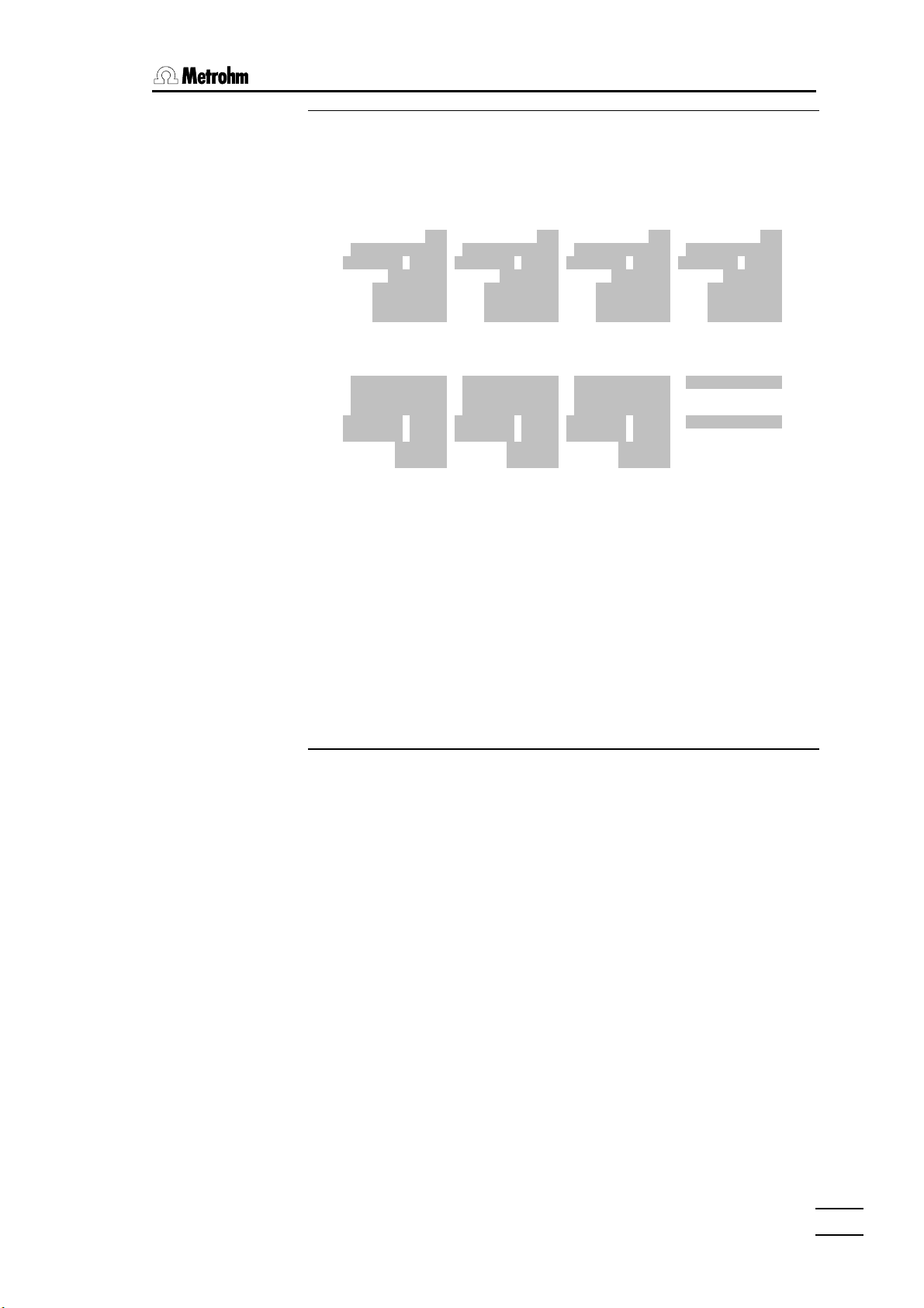
5. Methods and determinations
• Press the <MAN CONTROL> key in order to be able to operate the
dosing device manually.
ЪДДД Devices & Manual Control ДДДДДДДДДДДДДДДДДДДДДДДДДДДДДДДДДДДДДДДДДДДДДДДДД¿
³ ³
³ Dosing devices at interface A press <TAB> for more ³
³ ³
³ Dos. drive A1 700 A2 685 A3 --- A4 --- ³
³ Reagent ³
³ Concentr. ³
³ Tubing Default Default Default Default ³
³ Buret type 10.0mL 10.0mL --- --- ³
³ Piston position exchange exchange ----- ----- ³
³ Dosing status ready ready ----- ----- ³
³ДДДДДДДДДДДДДДДДДДДДДДДДДДДДДДДДДДДДДДДДДДДДДДДДДДДДДДДДДДДДДДДДДДДДДДДДДДДДД ³
³ Sensors at interface A press <TAB> for more ³
³ ³
³ Meas. input A1 A2 Adiff AT ³
³ Sensor ³
³ Cal. sensor ³
³ Cal. method Apol ³
³ Cal. date ³
³ Next calibr. ³
³ pH(as) 7.000 7.000 7.000 Stirrer on ³
³ Slope 1.000 1.000 1.000 ³
³ ³
АДДДДДДДДДДДДДДДДДДДДДДДДДДДДДДДДДДДДДДДДДДДДДДДДДДДДДДДДДДДДДДДДДДДДДДД QUIT ДЩ
ЪДДДДДДДВДДДДДДДВДДДДДДД¿ ЪДДДДДДДВДДДДДДДВДДДДДДД¿ ЪДДДДДДДВДДДДДДДВДДДДДДД¿
³Sample ³ Fill ³ Fill ³ ³Prepare³Dosing ³ Empty ³ ³ STOP ³ STOP ³Remote ³
³changer³ all ³ ³ ³buret ³drive ³ ³ ³ ³ all ³lines ³
АДДДДДДДБДДДДДДДБДДДДДДДЩ АДДДДДДДБДДДДДДДБДДДДДДДЩ АДДДДДДДБДДДДДДДБДДДДДДДЩ
[è][ç]
[Prepare]
Check the settings of the connected dosing device on the 'MANUAL
CONTROL' page. If no entries have been made under 'Reagent' and
'Concentr.' then no reagent check will be carried out. If different reagents are
often used this is probably the correct setting, otherwise please see page
53.
If the buret of the connected dosing device is equipped with the standard
tubing (dosing tubing 400 x 2 mm, …), then 'Default' must be entered
under Tubing. If the buret unit is not equipped with standard tubing then it
must be configured accordingly, see page 46ff.
• Use the cursor keys to select the required dosing device, make sure
that the buret tip of the attached buret unit is located in a rinsing beaker
and press the [Prepare] softkey.
All the tubing and the cylinder of the buret unit are now rinsed with a
sufficiently large amount of reagent to ensure that the buret unit is properly
filled without any air bubbles.
• After the sensor and the buret tip have been rinsed with a suitable
solvent the Titroprocessor is set up and the sample can be positioned.
Press <QUIT> to return to the main page of the Titroprocessor.
726 Titroprocessor, Instructions for use
• The <START> key can now be used to start the determination.
8383
Page 90

5.3 Determinations
5.3.3 System variables
A determination produces the following system variables which are available
for calculations :
MNR$$ mean value of the results R$$ in statistics memory
MNX$$ mean value of the intermediate results X$$ in statistics
MNC## mean value of the common variables C##
ID1 sample identification 1 (only numerical entries)
ID2 sample identification 2 (only numerical entries)
ID3 sample identification 3 (only numerical entries)
SS sample size (without units)
DD determination duration in s
$RN sample number
$AS autostart counter
$BC buffer counter
5.3.4 Determination files
Data produced during a determination are stored in a file in the working
memory while the determination is proceeding. The name of the
determination file and (optionally) file comments belonging to it are created
automatically according to the settings on the configuration page. Various
masks with combinations of determination time, sample number or sample
identifier, etc. are available, see page 34f.
memory
If the statistics function is switched off (see below) the file of the current
determination will always be kept in the working memory until a new
determination has been started.
After the start of a determination the determination data (results, curves,
etc.) of the previous determination are no longer contained in the working
memory. The current determination file in the working memory cannot be
deleted and remains in existence – just like the current method – even when
the instrument is switched off. An exception to this is the initialization of the
statistics function, see below.
Statisticsfunction
If the statistics function is switched on then the statistics counter limit
determines the number of the determination files which can be present in
the working memory (Statistics 'on' 1 of '10' => max. 10 files
in the working memory). Up to 20 determination files can be contained in
the working memory.
If during a sample series the statistics counter becomes filled up with the
number of determinations carried out then at the start of the next (surplus)
determination the statistics will automatically be initialized again. This means
that the working memory will be completely emptied and can start to be
filled up again with the following determinations.
The statistics can be initialized manually and in this way the working
memory (together with the current determination) can be totally cleared. This
process is recommended before a sample series is carried out. Select
Statistics 'rst' on the main page (this is not possible in the status
window).
8484
726 Titroprocessor, Instructions for use
Page 91

5. Methods and determinations
Auto save function
With the aid of the auto save function (Auto save 'on') determination
files can be automatically stored in the internal memory, on a data card or
(via an RS232 interface, see page 228) on a personal computer. Always
make sure that sufficient memory space is available for this.
If the auto save function is used then care must be taken that only unambiguous
and different file names are created. If an attempt is made to overwrite an existing
determination file with one with the same name the safety query which this
produces will interrupt the processing of the sample series. Use the possibility of
combining date, time and/or sample number for the automatic creation of file
names, see page 34f.
A typical determination which includes a titration requires approx. 5 - 10 KB
memory. The file manager can be used to determine the amount of free
memory in the internal memory or on a data card.
The file manager can be used to copy determination files at a later date or to
copy them onto a data carrier from the results window.
Determination data
The contents of a determination file also includes, apart from the measuring
data produced (measuring point lists of the titrations and measurements,)
the settings and parameters which are required for a re-evaluation together
with additional information which is used for a GLP-conform presentation of
the determination. Details can be found in the table below.
File name + File comments + File attribute
Method name with attribute
(local) Common variables + System variables
Sample data + Operator name
#1 Mode #2 Mode Up to 5 Modes
System variables System variables …
Measuring point list Measuring point list …
Evaluation and
presentation
parameters
Evaluation and
presentation
parameters
…
Formulas Formulas …
Report definitions Report definitions …
Calibration data Calibration data …
726 Titroprocessor, Instructions for use
Results Results …
Error list Error list …
Report header + Determination report definitions
Instrument identification
Date of determination
8585
Page 92

5.3 Determinations
5.3.5 Sample series
If a sample series is to be carried out automatically then the
corresponding method should be loaded in the way described for
single determinations on page 80.
In addition the following status settings should be made:
Statistics on for statistics calculations and/or re-
evaluations; increases the working memory
for the given number of determinations.
Auto save on the original determination data are stored in a
permanent memory.
Destination … depending on the memory requirements a
corresponding memory area can be selected.
Warning! The internal memory is limited to
1.5 Mbytes and if used to the full can impose
limits on the working memory.
Auto start on switch the autostart function on and enter the
number of samples. Not just a numerical
value can be entered.
* = indefinite number, infinite series
Silo = the complete sample silo will be
processed from the indicator marker onwards.
Rack = The whole of the sample rack on the
sample changer will be processed. *
Silo on unconditionally recommended for sample
series. Enter the sample data in the sample
silo first, set the start marker there and switch
the silo on.
Changer 1 the address of the sample changer used.
Sample pos. 1 rack position of the first sample
With 'Auto start Rack' the method used should be optimized in order
to ensure that the last determination in the sample series is carried out
correctly.
Insert the following two lines at the end of the method, but before the
definition of the closing sequence (CMOVE:
SAMPLE Function + Value 1
MOVE_S Sample to tower 1
8686
726 Titroprocessor, Instructions for use
Page 93
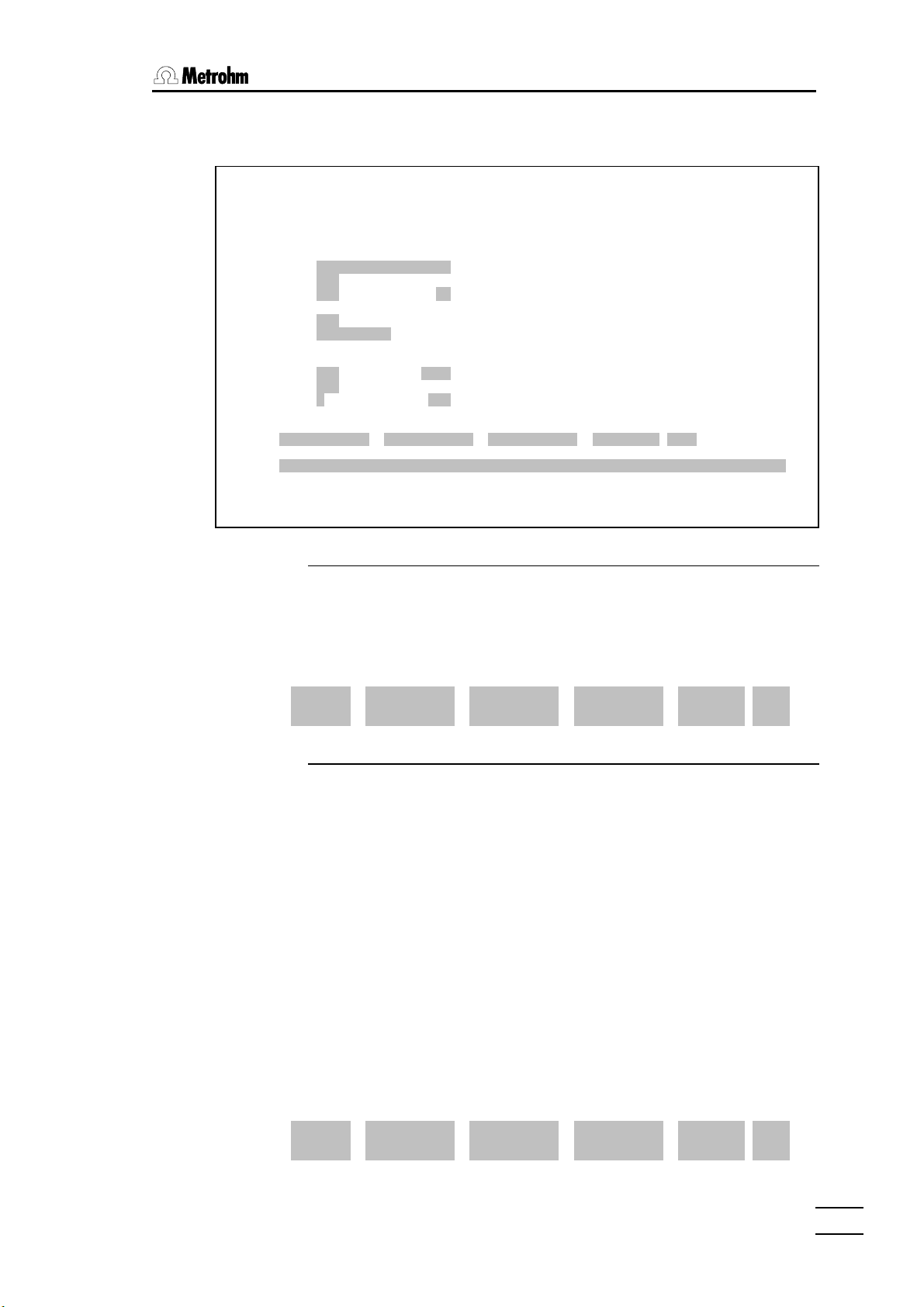
5. Methods and determinations
The main page of the Titroprocessor 726 should be similar to that shown
below:
1997-11-27 10:17:52 MAIN PAGE 726 Titroprocessor * ready *
Method 3455.mth Chloride in Tap Water
ДДДДДДДДДДДДДДДДДДДДДДДДДДДДДДДДДДДДДДДДДДДДДДДДДДДДДДДДДДДДДДДДДДДДДДДДДДДДДД
ЪДДДДДДДДДД Application Note ДДДДДДДДДДДДДДД¿
User B. Miller ³ Chloride in Tap Water ³
Run number 000 ³ ДДДДДДДДДДДДДДДДДДДДДДДДДДДДДДДДДДДДДДДДДД³
Statistics on 0 of 10 ³ ³
³ ³
Auto save on 78.7 % free ³ Pipet 100.00 mL tap water exactly in a ³
Destination Data card ³ 150 mL beaker. ³
Determ.name ³ ³
³ ³
Auto start on 0 of 10 ³ ³
Silo on in# 11 out# 1 ³ ³
Changer 1 Sample pos. 1 ³ ³
АДДДДДДДДДДДДДДДДДДДДДДДДДДДДДДДДДДДДДДДДДДДЩ
Ident1 Ident2 Ident3 Size Unit
Sample
Remark
ЪДДДДДДДДДДДДДДДДДДДДДДД¿ ЪДДДДДДДДДДДДДДДДДДДДДДД¿ ЪДДДДДДДДДДДДДДДДДДДДДДД¿
³Config.³Load ³File ³ ³Edit ³Show ³Results³ ³Sample ³Devices³Common ³
³ ³method ³manager³ ³method ³curves ³ ³ ³silo ³ManCtrl³vars ³
АДДДДДДДДДДДДДДДДДДДДДДДЩ АДДДДДДДДДДДДДДДДДДДДДДДЩ АДДДДДДДДДДДДДДДДДДДДДДДЩ
[Sample silo]
• To enter the sample data open the sample silo with the [Sample
silo]softkey.
ЪДДД Sample silo : NEW.slo ДДДДДДДДДДДДДДДДДДДДДДДДДДДДДДДДДДДДДДДДДДДДДДДДДДДД¿
³ ³
³ # Method Ident1 Ident2 Ident3 Size Unit ³
³ ДДД ДДДДДДДД ДДДДДДДДДДДД ДДДДДДДДДДДД ДДДДДДДДДДДД ДДДДДДДДД ДДДДД ³
³ <> 1 ³
³ 2 ³
³ 3 ³
• Now enter the sample data line by line. This can be done manually or
the sample weight can be transferred directly from a balance. In the
latter case the sample identifiers can be entered later by hand.
• If the necessary method has already been loaded then leave the
'Method' column empty. An entry would have the effect that before the
silo line involved is processed the given method is loaded into the
working memory.
• Further details about editing the sample silo can be found on page 92ff.
• In order to indicate which sample should be processed place the field
cursor on the line containing the sample data of the first sample. Press
the [ >> >> ] softkey to display the second softkey bar. Use the
[<-- Out pointer] softkey to set the silo output marker. This
always marks the next silo line to be processed with the '<' character. It
is carried out again for each determination.
³ # Method Ident1 Ident2 Ident3 Size Unit ³
³ ДДД ДДДДДДДД ДДДДДДДДДДДД ДДДДДДДДДДДД ДДДДДДДДДДДД ДДДДДДДДД ДДДДД ³
³ < 1 971120/1 12 3455 100 mL ³
³ 2 971120/1 12 3455 100 mL ³
³ 3 971120/2 15 3455 100 mL ³
726 Titroprocessor, Instructions for use
8787
Page 94

5.3 Determinations
³ 9 971120/5 25 3455 100 mL ³
³ 10 971120/5 25 3455 100 mL ³
³ > 11 ³
³ 12 ³
• If subsequently – possibly even as the sample series is being
processed – further sample data are to be transferred from the balance
to the Titroprocessor then set the silo input pointer to the next free silo
line. This is carried out in a similar way to setting the silo insert pointer
(softkey [--> In pointer]). The insertion mark '>' is moved on by
one line each time sample data are inserted.
• Now prepare the sample changer with the sample beakers. Place the
sample beakers on a sample rack and place this on the sample
changer. The sample changer will automatically recognize which rack is
in position when it is initialized. This is done by pressing the
<MAN CONTROL> key on the Titroprocessor and then the [Sample
changer] softkey.
• Initialize the sample changer by pressing the [Reset] softkey. This
should be carried out each time a sample rack is exchanged.
After the sample changer has moved to its starting position the correct
rack name should be shown in the sample changer dialog window. If
this is not the case then the sample changer and the rack definitions
must first be configured, see page 38ff.
ЪДДД Devices & Manual Control ДДДДДДДДДДДДДДДДД
³ ЪДДД Sample changer ДДДДДДДДДДДДДДДДДДДДДД
³ Do³
³ ³ Changer 1: ready [000001]
³ Do³ ДДДДДДДДДДДДДДДДДДДДДДДД
³ Re³ Rack type/name M12-0 - 12*250mL
³ Ko³ Max. beaker 12
• Now use the softkeys [Shift left], [Shift right], [Lift
up] [Lift down] to rotate the sample rack so that a rinsing beaker
is positioned under the titrating head which has been fitted up. Please
note that the rack can only be rotated when the lift (or both lifts for
models with two lifts) is located in the upper rotate position defined in
the configuration.
• Move the lift to the working position and prepare the buret units as
described under 'Single determinations ' (page 83).
• The entry 'Sample pos.' can be found on the main page. This
determines the first rack position in the sample series. The beaker
position which contains the first sample should be entered here. This
must not necessarily be position 1.
• Initialize the statistics (Statistics 'rst') in order to clear the
working memory and create enough space for the determination data of
the sample series.
8888
• All necessary settings have now been made. Press the <START> key
to start the sample series.
726 Titroprocessor, Instructions for use
Page 95
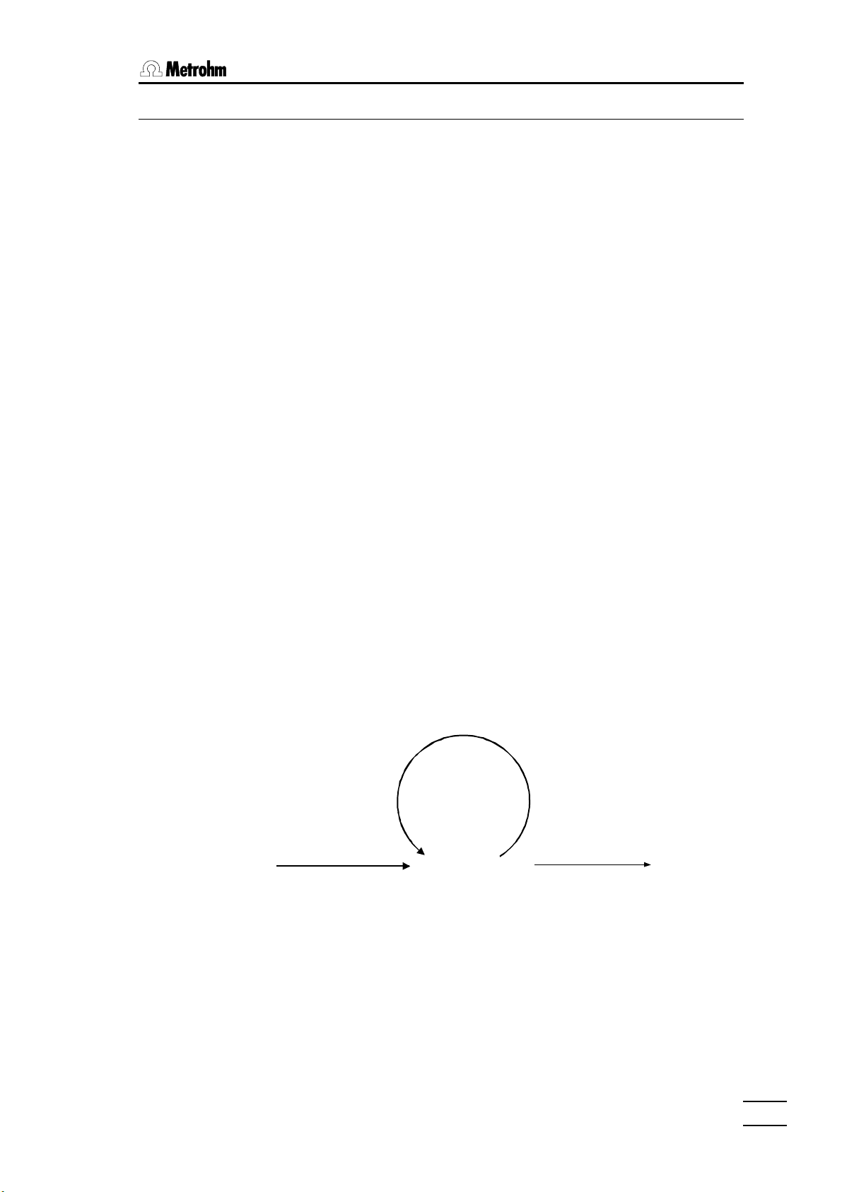
5.3.6 Course of a sample series
The following points should be taken into account:
• Check whether all sample beakers have been placed on the rack
correctly. It is absolutely necessary that the beaker containing the first
sample of the series is present. Other sample beakers can be added as
the series is being processed.
• After the start of the sample series the necessary storage space is
reserved in the working memory according to the settings under
'Statistics'. If not sufficient storage space is available the process
will be interrupted.
• During the first determination of the series command sequence defined
in the methods of the OMOVE(…)OMOVE loop will be carried out a single
time.
• In the following determinations in the series the neither the
OMOVE(…)OMOVE nor the CMOVE(…)CMOVE loops will be carried out
(see below).
5. Methods and determinations
• In the last determination in the sample series the CMOVE(…)CMOVE
loop defined in the method will be carried out.
These start and closing sequences are provided specially for sample
changer operation and can be used e.g. for conditioning or regenerating
sensors. For these applications the use of special beakers on the sample
rack is a good idea (see configuration, page 41).
Course of a sample seriesCourse of a sample series
number of
samples
Start sequence OMOVE
<START>
It is not absolutely necessary these start and closing sequences
(OMOVE/CMOVE) are defined at the start or end of a method. However,
please note that the method is processed strictly according to the sequence
of defined command lines.
Sample sequence
Final sequence CMOVE
normal state
726 Titroprocessor, Instructions for use
8989
Page 96

5.3 Determinations
Statistics and sample series
In certain cases it may be a good idea to set the statistics limit to a lower
value than the total number of samples. If double or triple determinations
are to be carried out on the same sample within a sample series and
statistical data are to be calculated for each of them then the statistics limit
should be set to 2 or 3 respectively.
The statistical calculations are carried out for each sample but with these
settings the statistics are reset after each 2 or 3 determinations and the
working memory cleared. In this way statistical calculations are obtained for
double or triple determinations.
Warning! Statistical results are only calculated according to formulas which
have been defined as a 'Statistics formula' (formula type 'stat.') in the
formula editor. The statistics should be initialized before the start of a
sample series.
9090
726 Titroprocessor, Instructions for use
Page 97

6. Sample data and sample silo
6 Sample data and sample silo
A data record can be entered for each sample. This data record contains:
• Sample identifiers (Ident1, Ident2, Ident3)
• Sample weight and units
• Comment line
For identification simple descriptive texts or numerical values can be used;
the numerical values can be used in calculations (system variables ID1,
ID2, ID3). The names and the type of field (text, numerical, auto) can be
altered to suit your requirements, see page 96.
The comments line can be used for clearly specifying a sample and can be
used for the creation of automatic file comments (see page 34f).
The sample weight is normally used for calculations (system variable SS). It
can be entered manually or from a balance via the RS232 interface(s) even
while a determination is taking place. It is additionally possible to enter all
sample data with a barcode reader.
6.1 Sample data entry
There are several different ways of entering sample data:
For single determinations (Silo ‘off’)
• Manual input in sample data section of the main page of the
Titroprocessor.
• Manual input in the dialog window ‘Current sample’, with the
<SAMPLE> key on the keyboard.
• Manual input with the command ‘ASK‘ during a determination run, see
page 206f.
• Automatic data input with data transfer from a balance.
With sample series (Silo ‘on’)
• Manual input in sample silo.
• Automatic data input in sample silo by data transfer from a balance.
6.1.1 Direct data transfer from balances
Most balances used in laboratories allow the sample weight (and units and
sample identification, depending on the model) to be transmitted directly to
the Titroprocessor via an RS232 interface. This receives the data in a special
data buffer and interprets the transmitted data according to the balance
type set.
In this way it is possible to enter the sample data at any time (even while a
determination run is being carried out) correctly in the current sample data
record or in the sample silo.
726 Titroprocessor, Instructions for use
9191
Page 98

6.2 Sample siloSample silo
A precondition for this is the correct definition of the type of balance and the
correct setting of the data transmission parameters in the Titroprocessor
configuration (page 44).
Consult the manual of your balance and make sure that the sample data
from the balance are transmitted with the line limit characters CR and LF
and that the data transmission parameters (baud rate, etc.) agree with those
of the Titroprocessor.
For further details please see page 26f.
6.1.2 Bar-code reader
A bar-code reader can be used wherever the manual input of data is
possible. This is connected to the 'Barcode' socket on the rear panel of the
Titroprocessor. Intelligent bar-code readers recognize the type of bar-code
automatically and convert it into an ASCII character sequence which the
Titroprocessor accepts as if it had been entered via the keyboard. Please
consult your local Metrohm agency.
See also pages 29 and 284.
6.2 Sample silo
The sample silo is a table consisting of 160 lines for accepting the data of a
sample series. It is selected by pressing the [Sample silo] softkey on
the main page.
• The whole sample silo can be deleted with [File] and [New].
• An empty sample silo consists of a single line. New lines are created by
• In principle the contents of the sample silo remains in existence when
• The contents of the sample silo can be stored and (with the [File]
pressing the key combination <ññ><êê> (shift – cursor).
the individual silo lines have been processed. Individual lines can be
marked ([UN/Mark]) softkey and deleted with the [Delete
line(s)] softkey.
softkey) can be read in again from the internal memory, from a data card
or even from a PC via an RS232 interface (see page 228). Productspecific sample silos can also be created and copied to several
Titroprocessors.
9292
726 Titroprocessor, Instructions for use
Page 99

6. Sample data and sample silo
ЪДДД Sample Silo : NEW.slo ДДДДДДДДДДДДДДДДДДДДДДДДДДДДДДДДДДДДДДДДДДДДДДДДДДДД¿
³ ³
³ # Method Ident1 Ident2 Ident3 Size Unit ³
³ ДДД ДДДДДДДД ДДДДДДДДДДДД ДДДДДДДДДДДД ДДДДДДДДДДДД ДДДДДДДДД ДДДДД ³
³ <> 1 19980120/2 B5 3455 100 mL ³
³ 2 ³
³ 3 ³
³ 4 ³
³ 5 ³
³ 6 ³
³ 7 ³
³ 8 ³
³ 9 ³
³ 10 ³
³ 11 ³
³ 12 ³
³ 13 ³
³ 14 ³
³ 15 ³
³ 16 ³
³ 17 ³
³ 18 ³
³ 19 ³
АДДДДДДДДДДДДДДДДДДДДДДДДДДДДДДДДДДДДДДДДДДДДДДДДДДДДДДДДДДДДДДДДДДДДДДД QUIT ДЩ
ЪДДДДДДДВДДДДДДДВДДДДДДД¿ ЪДДДДДДДВДДДДДДДВДДДДДДД¿ ЪДДДДДДДВДДДДДДДВДДДДДДД¿
³Remark ³File ³Un/Mark³ ³Insert ³Copy ³Delete ³ ³Un/Mark³Edit ³ >> ³
³ ³ ³ ³ ³line ³line(s)³line(s)³ ³all ³mode ³ >> ³
АДДДДДДДБДДДДДДДБДДДДДДДЩ АДДДДДДДБДДДДДДДБДДДДДДДЩ АДДДДДДДБДДДДДДДБДДДДДДДЩ
The normal view shows the sample data line by line. By pressing the
[Remark] softkey a descriptive note can be entered for each silo line (or
sample), which will be printed out in a report as a part of the sample data.
The [Sample silo] softkey returns the display to the standard view.
ЪДДД Sample Silo : NEW.slo ДДДДДДДДДДДДДДДДДДДДДДДДДДДДДДДДДДДДДДДДДДДДДДДДДДДД¿
³ ³
³ # Remark ³
³ ДДД ДДДДДДДДДДДДДДДДДДДДДДДДДДДДДДДДДДДДДДДДДДДДДДДДДДДДДДДДДДДДДДДДДДДД³
³ <> 1 Sample of 01/20/1998 ³
³ 2 ³
³ 3 ³
³ 4 ³
³ 5 ³
³ 6 ³
³ 7 ³
³ 8 ³
³ 9 ³
³ 10 ³
³ 11 ³
³ 12 ³
³ 13 ³
³ 14 ³
³ 15 ³
³ 16 ³
³ 17 ³
³ 18 ³
³ 19 ³
АДДДДДДДДДДДДДДДДДДДДДДДДДДДДДДДДДДДДДДДДДДДДДДДДДДДДДДДДДДДДДДДДДДДДДДД QUIT ДЩ
ЪДДДДДДДВДДДДДДДВДДДДДДД¿ ЪДДДДДДДВДДДДДДДВДДДДДДД¿ ЪДДДДДДДВДДДДДДДВДДДДДДД¿
³Sample ³File ³Un/Mark³ ³Insert ³Copy ³ ³ ³Un/Mark³Edit ³ >> ³
³silo ³ ³ ³ ³line ³line(s)³ ³ ³all ³mode ³ >> ³
АДДДДДДДБДДДДДДДБДДДДДДДЩ АДДДДДДДБДДДДДДДБДДДДДДДЩ АДДДДДДДБДДДДДДДБДДДДДДДЩ
726 Titroprocessor, Instructions for use
9393
Page 100

6.2 Sample siloSample silo
The individual silo columns:
Pointer column The output pointer '<' marks the next line to be
processed.
The input pointer '>' marks the next line in which
sample data from a balance can be entered.
# Line number
Method Method which can be loaded from the internal memory
or from a data card to process the sample. No entry
means that the method which is currently loaded in the
working memory will be used. A selection list of the
available methods is available for this input field (in the
internal memory). The names of the methods on a data
card must be entered manually.
Ident1…3 Sample identifiers. The type of input field can be
configured for each column (softkey
[Probenident.])
Size Sample size
Unit Sample weight unit. The fields in this column have a
selection list available.
Softkeys
[Remark] switches the dialog window to the view of the sample
notes in the silo lines.
[File] opens the file dialog window for loading and storing silo
files.
[Un/Mark] marks or removes the markers from individual silo
lines for copying or deleting.
[Insert
line] inserts an empty silo line in front of the current line.
[Copy copies the marked silo lines and inserts them in front
line(s)] of the current line.
[Delete deletes the marked silo lines. If no line has been
line(s)] marked then the current line will be deleted.
[Un/Mark marks or removes the markers from all silo lines.
all]
9494
[Edit opens the dialog window for setting the edit mode.
mode]
[ >> switches to second softkey bar.
>> ]
726 Titroprocessor, Instructions for use
 Loading...