

Page 1

CH-9101 Herisau/Switzerland
Tel. +41 71 353 85 85
Fax +41 71 353 89 01
E-Mail sales@metrohm.ch
Internet http://www.metrohm.ch
717 Sample Changer
Instructions for use
8.717.1003
98.03 sn
Page 2

Table of Contents
Page
1 OVERVIEW ___________________________________________ 1
1.1 Side View _______________________________________ 1
1.2 Rear View _______________________________________ 2
1.3 Sensors _________________________________________ 3
1.4 The Sample Changer Models _______________________ 4
2 INSTALLATION ________________________________________ 5
2.1 Setting up the Instrument __________________________ 5
2.2 Safety Considerations _____________________________ 6
2.3 Arranging the Accessories _________________________ 7
2.3.1 Setting up the Rinsing Equipment .................................7
2.3.2 Tubing Fixation ..............................................................8
2.3.3 Magnetic Stirrers ...........................................................8
2.3.4 Sample Racks ...............................................................9
2.3.5 Mounting and Setting up the Titration Heads ..............10
2.4 Remote Connections _____________________________ 11
2.5 External Bus Connections ________________________ 13
3 SAMPLE RACKS ______________________________________14
4 SWING HEAD ________________________________________ 16
4.1 Prerequisites ___________________________________ 16
4.2 Installing the Swing Head _________________________ 16
4.3 Accessories for the Titration Head _________________ 18
5 APPENDIX __________________________________________ 20
5.1 Technical Specifications __________________________ 20
5.1.1 717 Sample Changer ..................................................20
5.1.2 759 Swing Head ..........................................................22
5.2 Servicing and Maintenance _______________________ 23
5.3.1 Servicing ......................................................................23
5.3.2 Maintenance / Attendance ...........................................23
5.3 Warranty and Conformity _________________________ 24
5.3.1 Warranty ......................................................................24
5.3.2 Certificate of Conformity and System Validation
for the 717 Sample Changer ...............................25
5.3.3 Certificate of Conformity and System Validation
for the 759 Swing Head .......................................27
5.4 Accessories ____________________________________ 29
5.5 Index __________________________________________ 34
Page 3
1 Overview
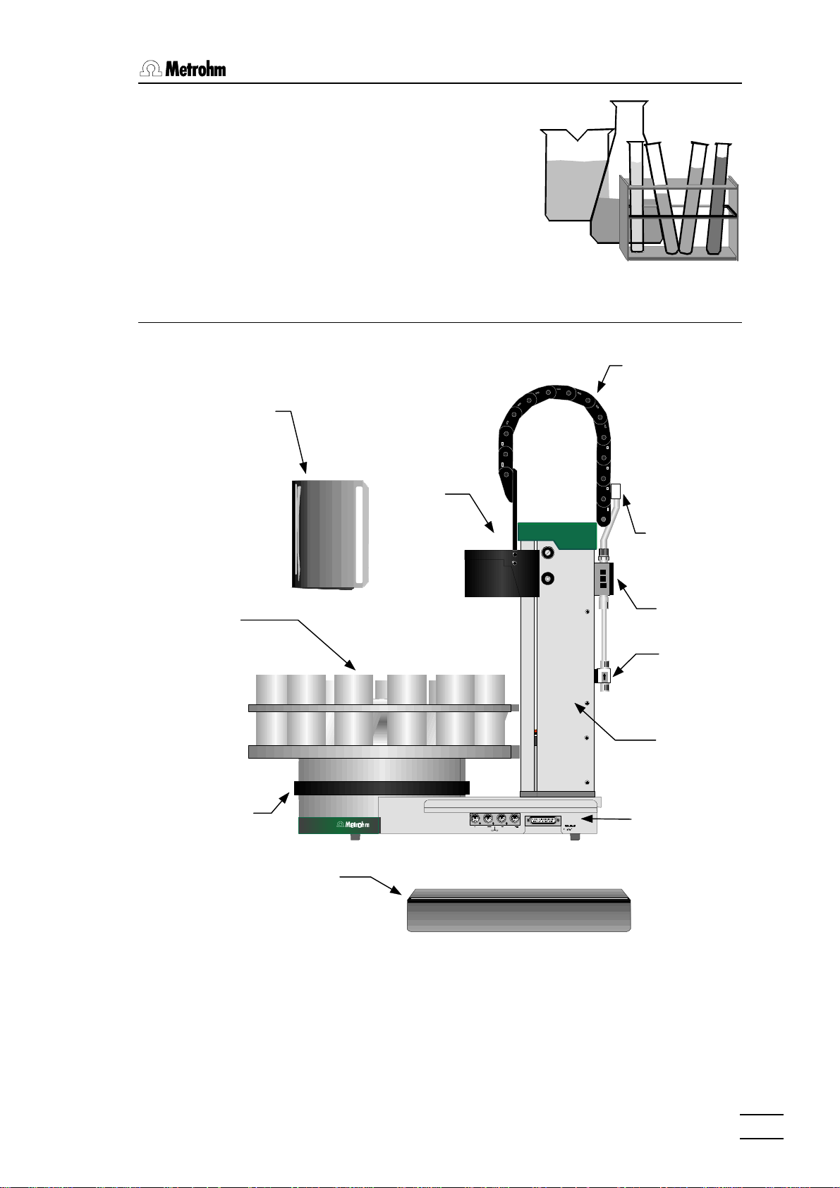
1.1 Side View
1.1 Side View
Splash protection
Rack
Guide chain
Lift
Distribution
head
Pump
Valve
Tower
Stirrer rail
717 Sample Changer, Overview
Connectors
Plug cover
Safety note:
Do not operate the 717 Sample Changer without splash protection
and plug cover being mounted. The plug cover prevents any contamination of the connectors, caused by spilled solvents or chemicals.
1
Page 4
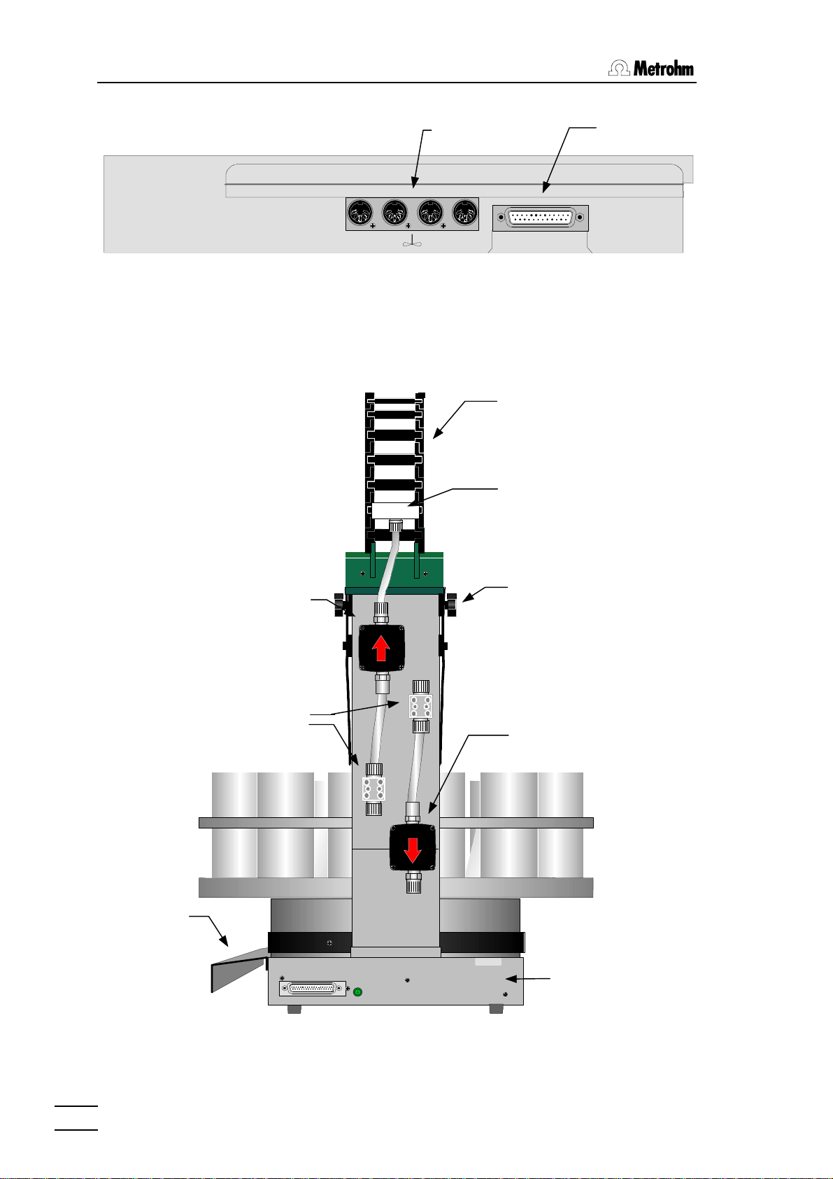
1.2 Rear View
The Connectors (side view):
The remote socket serves the connection of Metrohm- or other
measuring instruments that communicate via a serial cable.
1.2 Rear View
Stirrer
sockets
1 2 3 4
Remote
socket
Remote
Control
Guide chain
Distribution head
Plug cover
Pump 1
Valves
External Bus
Address
0020/02 187
Type 1.717._
Made by Metrohm Herisau Switzerland
Mounting screw
for splash protection
Pump 2
Connectors
2
717 Sample Changer, Overview
Page 5
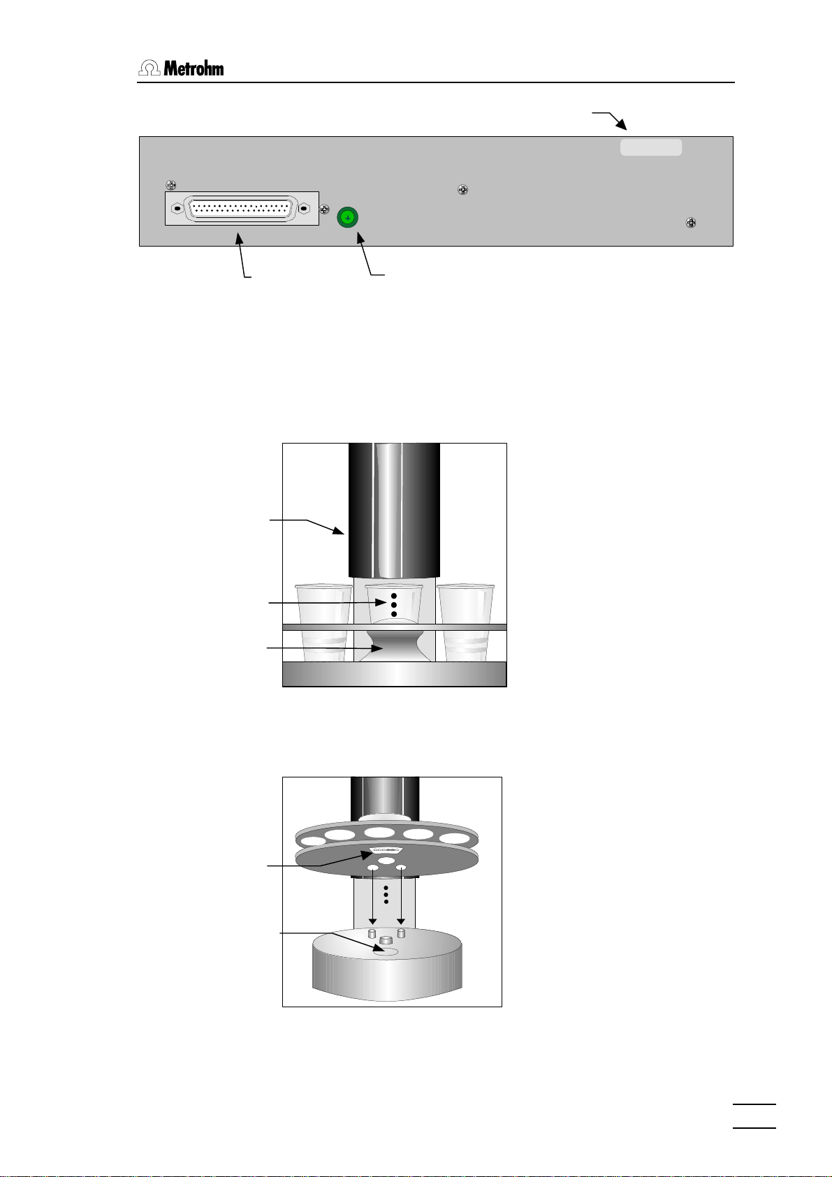
1.3 Sensors
The Connectors (rear):
External Bus
External Bus
socket
1.3 Sensors
Beaker test
Splash protection
Beaker indicator
Address
Manufacturing number
External Bus
address selector
Type 1.717._
Made by Metrohm Herisau
0120/02 187
Each tower of the 717 Sample
Changer is equipped with a
beaker indicator to detect the
presence of a beaker in front
of the particular tower. This
infrared sensor detects many
different materials, if any object is placed in correct position.
Rack
Magnet holder
Magnetic indicator
Front view
Magnetic rack code indicator
The magnetic sensor to detect
the individual rack codes is
mounted below the sample
changer's turntable.
The 717 Sample Changer
should be initialized right after
every rack change, because the
magnetic binary code of the
racks can only be read, if the
rack is in initial position and
therefore the magnet holder is
in accurate position right above
the rack code indicator.
717 Sample Changer, Overview
3
Page 6
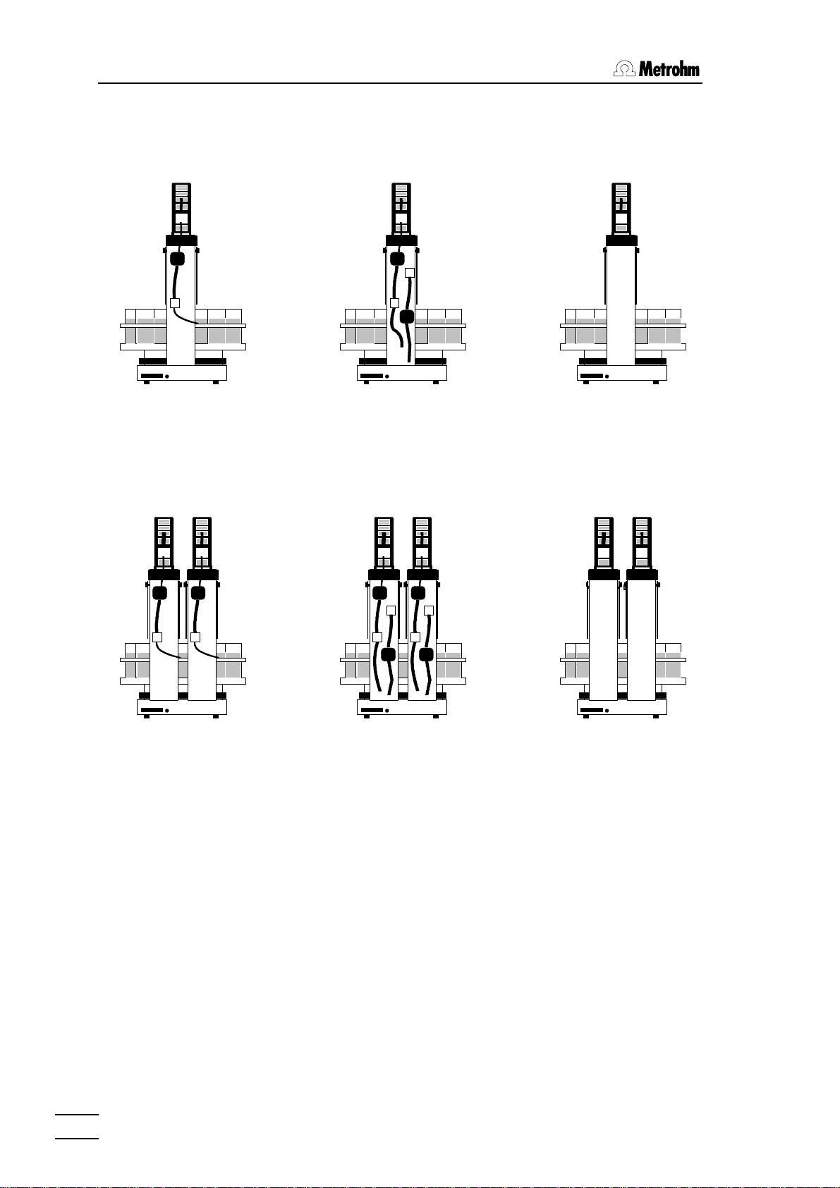
1.4 The Sample Changer Models
11.4 .4 The Sample Changer Models
Model 2.717.0010 Model 2.717.0020 Model 2.717.0030
1 tower, 1 pump 1 tower, 2 pumps 1 tower, no pumps
2 stirrer connections 2 stirrer connections 2 stirrer connections
Tower 1
Tower 2
Tower 1
Tower 2
Tower 1
Model 2.717.0110 Model 2.717.0120 Model 2.717.0130
2 towers, 2 pumps 2 towers, 4 pumps 2 towers, no pumps
4 stirrer connections 4 stirrer connections 4 stirrer connections
Tower 2
4
717 Sample Changer, Overview
Page 7

2 Installation
2.1 Setting up the Instrument
Packaging
The 717 Sample Changer is supplied with the accessories in
separate special packages designed to ensure maximum protection. These contain shock-absorbing foam linings. As only these
special packages guarantee damage-free transport of the instrument, it is essential you store them in a safe place.
Control
Immediately following delivery, check that the consignment is
complete and undamaged (compare with delivery note and accessories list, page 29ff). In case of damage, see "Warranty",
page 24.
2.1 Setting up the Instrument
Setting up
The 717 Sample Changer is a rugged instrument and may be
used in rough environments such as laboratories and manufacturing plants. It must not be exposed to a corrosive atmosphere.
If the sample changer is operated in a rough environment, regular
maintenance is strongly recommended.
717 Sample Changer, Installation
5
Page 8

2.2 Safety Considerations
2.2 Safety Considerations
If failure or malfunctioning occurs during operation of the
717 Sample Changer, the Metrohm Service Department should be
consulted.
If opening the instrument is unavoidable, the following safety precautions are to be strictly adhered to:
Before opening the instrument disconnect it from all electrical sources. Make sure that all main cables have been disconnected.
Only in exceptional cases should the instrument be opened while it
is switched on. Because parts that conduct current are exposed in
this case, this should only be undertaken by an expert who is acquainted with the associated dangers.
Electronic components are sensitive to static electricity and can be
destroyed by discharge. Before touching any components inside
the instrument, both the person and his tools should be grounded
by grasping a grounded object (for example: a metallic part of the
casing of the instrument or a radiator) in order to eliminate any
static electricity.
When peripheral instruments are connected to the 717 Sample
Changer, the sample changer and the instruments to be connected have to be switched off, otherwise all instruments could
suffer damage.
If it becomes apparent that the instrument can no longer be operated safely, it must be put out of operation.
6
717 Sample Changer, Installation
Page 9

2.3 Arranging the Accessories
2.3.1 Setting up the Rinsing Equipment
To mount the PTFE tubings to the pump inlets or outlets enlarge it
carefully using a screwdriver, a pen or another appropriate tool. A
piece of sand paper facilitates grasping of the tubing.
The arrangement of the tubing depends on the rinsing equipment.
Rotating nozzle
Using a changer model with one pump per tower only, the rotating
nozzle (6.2740.000) is recommended for rinsing. The Teflon tubing
is then directly connected to the rinsing pump (pump 1). The distribution head may be dismounted in this case.
2.3 Arranging the Accessories
Place the rotating nozzle vertically in the titration head with the aid
of a SGJ14/12 mm sleeve.
Spray nozzles
When using a changer model with two pumps per tower, spray
nozzles (6.2740.020) may be used in combination with an aspiration tip M8 (6.1543.170). Insert the spray nozzles into the sloped
borings of the titration head. Use Teflon tubings to connect them
to the distribution head. Each of the four outlets of the distribution
head must be plugged. Plug unused outlets with an M6 thread
stopper (6.1446.040) to avoid splashing of liquid during rinsing.
Fix the tubings in the guide chain. Chain links may be removed if
necessary (see below).
Insert the aspiration tip vertically into a boring (SGJ9) of the Macro
Titration head. The Micro Titration head offers also a vertical boring for the placement of the aspiration tip. Connect the tip with the
Teflon 4/6 tubing (6.1805.510) and a screw connector 4/6 mm
(6.1820.030) to pump 2 (valve marked with 'ê'). During the rinsing
procedure, first the sample is sucked off then the electrode is
rinsed in the empty vessel.
717 Sample Changer, Installation
7
Page 10
2.3 Arranging the Accessories
The pump heads of the diaphragm pump, the fittings and the coupling rings are made of PVDF. PVDF is resistant to many chemicals. Acetone, acetanhydride or dimethylformamide (DMF) should
not be used. The diaphragm, and the inner parts of the valves
consist of PTFE and are resistant to most chemicals.
If your samples contain solids (e.g. silver chloride) or sticking substances, you should use the 772 Peristaltic Pump Unit in combination with the 731 Relay Box instead of the diaphragm pump integrated into the changer.
The PE canisters (6.1621.000) are suitable for aqueous solutions.
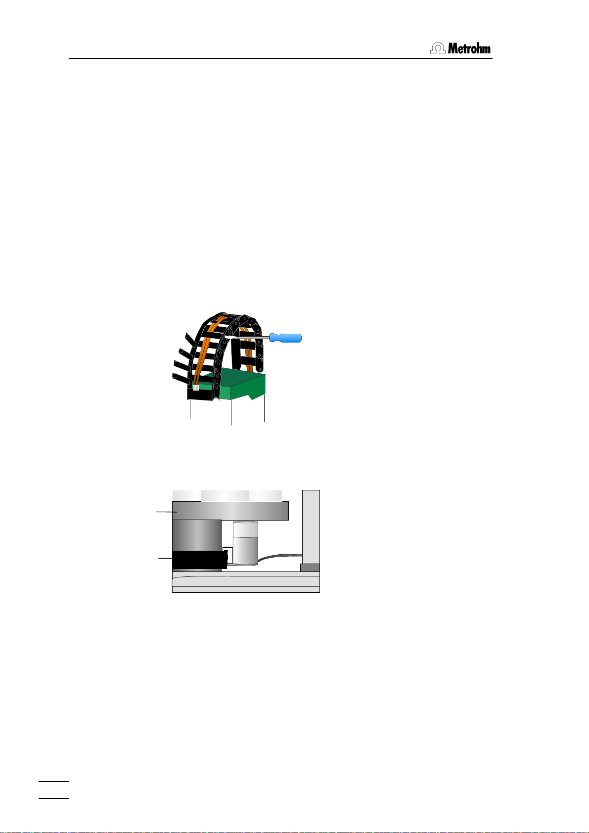
2.3.2 Tubing Fixation
In order to fix the tubing in
the guide chain any chain link
may be opened with a screw
driver or another appropriate
tool.
2.3.3 Magnetic Stirrers
Rack
Stirrer rail
Magnetic stirrers 2.741.0010
may be placed in any
position on the stirrer rail
beneath the rack.
8
717 Sample Changer, Installation
Page 11
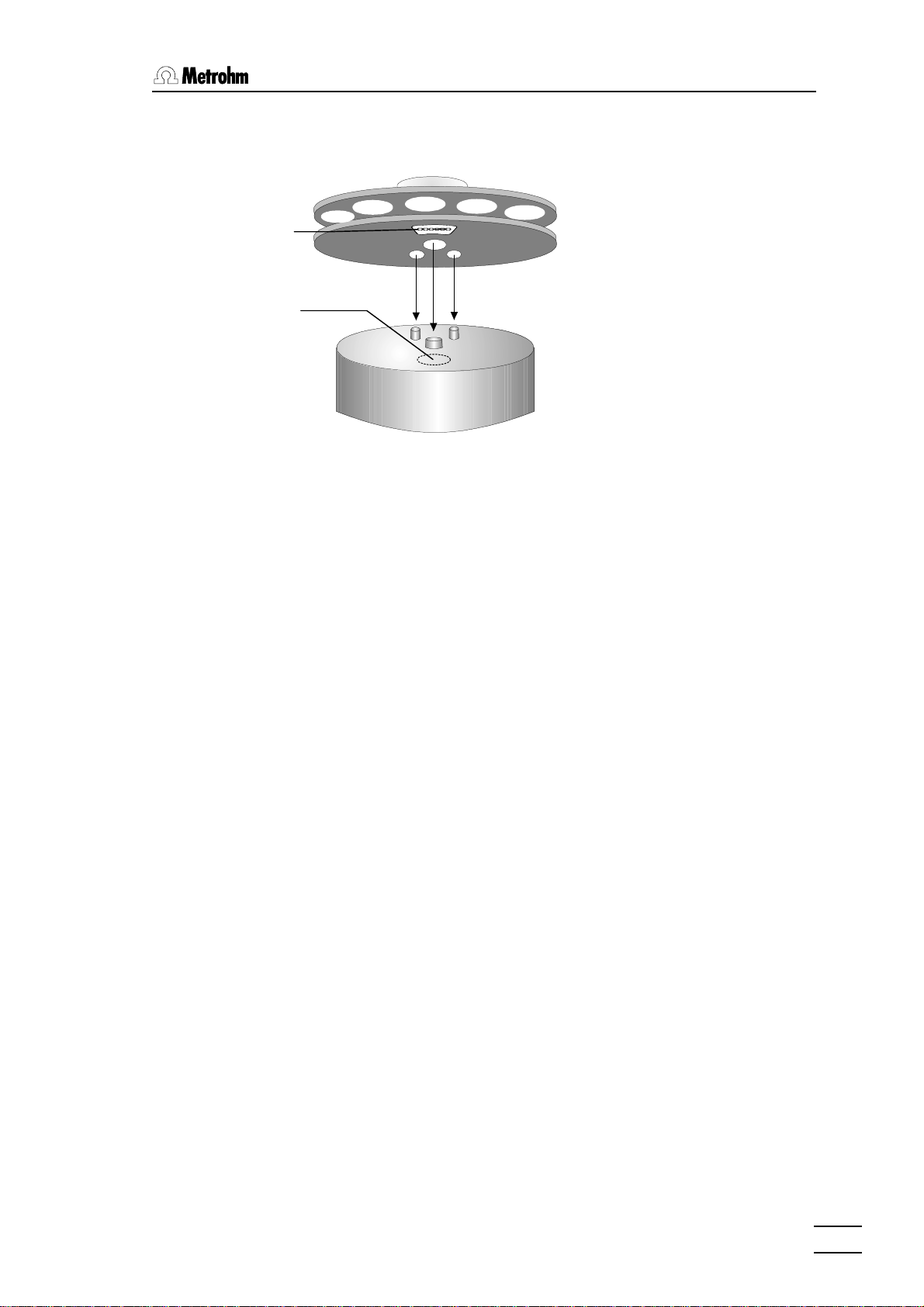
2.3.4 Sample Racks
Magnet holder
Magnetic sensor
2.3 Arranging the Accessories
After placing the rack on the
turntable, the sample
changer must be initialized to
enable the safe reading of
the magnetic rack code.
This can only be done if rack
position 1 is directed to
tower 1.
717 Sample Changer, Installation
9
Page 12

2.3 Arranging the Accessories
2.3.5 Mounting and Setting up the Titration Heads
Macro Titration head
6.1458.010
Micro Titration head
6.1458.020
Mounting screws
Aspiration tip M8
(also for Macro Titration head )
6.1543.170
Electrode
Rotating nozzle
6.2740.000
Burette tip
Rod stirrer
2.722.0020
M6 Spray nozzles
(also for Macro Titration head)
6.2740.020
SGJ14 sleeve
6.1236.020
M8 Thread stopper
4.658.0180
SGJ9 Guide sleeve
6.2709.070
Stirrer propeller
6.1909.020
Use only the designated
Micro electrodes with the
Micro Titration head, see
accessory list, page 33.
Note on Macro Titration head
The arrow sign marks the slightly sloped SGJ boring, which enables to center a rod
stirrer or an electrode in a narrow titration vessel.
10
717 Sample Changer, Installation
Page 13

2.4 Remote Connections
2.4 Remote Connections
665
725
Dosimat
759 Swing Head
711 Liquino
Remote
Valves
Pumps,
e.g. 772
717 Sample Changer
731 Relay Box
Connecting peripheral instruments to the 717 Sample Changer requires Metrohm cables. Otherwise a safe data transmission may
not be guaranteed.
All instruments have to be switched off, before they are connected. Otherwise the instruments could suffer from damage.
14 lines (Output 0–13) are available for the emission of signals.
For receiving signals 8 lines are provided (Input 0–7).
Pin assignment of the Remote socket:
0 Volt
+5 Volt
Output 5
Output 3
Output 1
Output 12
Output 13
Input 0
Input 2
Input 4
Input 6
0 Volt
Output 6
Output 7
Output 4
Output 2
Output 0
Output 8
Output 9
Output 10
Input 1
Input 3
Input 5
Input 7
Output 11
+5V
Inputs
active = low
inactive = high
Outputs
active = low
inactive = high
717 Sample Changer, Installation
The +5 V supply line may by charged with 20 mA maximally.
11
Page 14

2.4 Remote Connections
The required cables are listed in the following table. Details about
the control commands are given in the Instructions for use of the
corresponding instrument.
717 Sample Changer with 759 Swing Head
In order to increase the number of samples, the 759 Swing Head
with a titration head (2.759.0020) or a transfer head (2.759.0010)
can be installed in place of a normal titration head. In this way the
titration head can be moved very accurately to the individual vessels located in several rows on the sample rack. You will find a
more detailed description in the chapter "Swing Head", page 16.
Instrument Cable
665/725 Dosimat 6.2139.000
711 Liquino 6.2141.020
731 Relay Box 6.2125.100
12
730
Connection of further
instruments via the
remote interface
The 759 Swing Head is connected via the remote interface with a
special cable. Using the remote cables for the sample changer,
additional instruments can be connected to the remote socket,
while four lines (Input 7 and Output 11–13) are occupied by the
swing head. These four lines are ignored when the swing head is
switched on in the configuration, they are not continued in the
plug.
717 Sample Changer, Installation
Page 15

2.4.1 External Bus Connections
Via the "External Bus" the 717 Sample Changer is operated by a
control instrument, e.g. the 726 Titroprocessor.
Four dosing instruments (Dosimat 685 or Dosino 700) may be
connected to the "External Bus" interface using a 729 Dosimat
Interface. Up to two Dosimat Interfaces may be connected in line
(daisy chaining) and be assembled with dosing instruments. Each
interface must be addressed correctly.
Before the instruments are connected, all devices have to be
switched off.
2.4 Remote Connections
EBus
Adress 0
Control instrument
Dos. 2
Dos. 1
Dos. 1...4
700685
685
700
717
EBus
Adress 1
Cable 6.2135.000
729
Dos. 3
EBus
Adress 1
Cable 6.2134.000
Dos. 4
729
EBus
Adress 2
Devices such as sample changers which consume a lot of current
should be connected in the first position of the EBus chain behind
the control instrument.
Addresses:
"External Bus"-
Dosing Unit
Address
Control instrument 0 Dos. 1 … Dos. 4
1. 717 Sample Changer 1
2. 717 Sample Changer 2
1. Interface 1 Dos. 1 … Dos. 4
2. Interface 2 Dos. 1 … Dos. 4
717 Sample Changer, Installation
The corresponding EBus address can be set with a screwdriver on
the EBus address selector that is located on the rear panel of the
device (see p. 3).
13
Page 16

3 Sample Racks
3 Sample Racks
A sample rack is a sort of turntable for the positioning of beakers
which are to be placed on the 717 Sample Changer. Because for
titration, various sizes of beakers are common or required, many
kinds of racks can be used and are easily interchangeable. The
rack offers space for various numbers of samples depending on
the diameter of the beakers. Metrohm delivers the following predefined types of standard racks:
Type Number of
beakers
M12-0 12 *) 250 mL Metrohm glass beaker 000001 6.2041.310
M12-0 12 *) 150 mL glass beaker or
M14-0 14 200 mL disposable beaker (Euro) 000011 6.2041.370
M14-0 14 8 oz disposable beaker PP (US) 000101 6.2041.380
M16-0 16 150 mL glass beaker 000010 6.2041.320
M16-0 16 120 mL disposable beaker (US) 100001 6.2041.390
M24-0 24 *) 75 mL Metrohm glass beaker 001000 6.2041.340
M48-1 48 75 mL Metrohm glass beaker 010000 6.2041.350
M128-2 126
2
Type of beaker Predef.
Code
100000 6.2041.360
200 mL disposable beaker (Euro)
15 mL test tubes
250 mL Metrohm glass beaker
*) Parallel titration at two towers possible.
If desired, other user-defined racks can be delivered. Irregular arrangements of beaker positions are also possible.
Every single rack can be identified by a unique magnetic code.
Rod magnets which are attached to the bottom of the rack can be
combined to form a 6-place binary code. The sample changer can
then automatically recognize the mounted rack. This is possible
when the rack is positioned with the first rack position in front of
tower 1. When changing a rack, the sample changer should first
be reset to the normal position. This way the save recognition of a
rack and therefore the correct beaker positioning is made possible. An internal position table containing the unambiguous definition of the turning angles and beaker positions is assigned to each
rack type.
This position table is stored in the control device.
001010 6.2041.400
Order
Number
14
717 Sample Changer, Sample Racks
Page 17

3 Sample Racks
The standard racks provided by Metrohm are already equipped
with a predefined magnetic code for every rack type. If several
racks of the same type are used, the magnet rods can be arranged differently so that a unique identification of a sample rack
is possible, if this is desired.
Format of a magnetic code (example):
000001 i.e. only one magnet is inserted, bit 0
000101 i.e. two magnets are inserted, bit 0 and 2
63 different combinations are possible. The code 000000 stands
for "no code defined".
Magnets inserted
In this example the
code is: 000110
bottom view
717 Sample Changer, Sample Racks
15
Page 18

4.1 Prerequisites
4 Swing Head
To ensure that the individual vessels are approached with precision even when using multiple-row sample racks, a 759 Swing
Head can be installed instead of the normal titration head. The
swing head is fitted with either a titration head (2.759.0020) or a
transfer head (2.759.0010) for pipetting the sample from the sample vessel into a bigger titrating vessel.
4.1 Prerequisites
The 759 Swing Head can be used in combination with the following racks:
Sample rack 759 model Number of
towers
Titration 48 x 75 mL for direct titration
Article No. 6.2041.350
Pipetting 126 x 15 mL and
2 x 150 mL for pipetting
Article No. 6.2041.400
If the two-row sample rack with 48 beakers is used on the 2-tower
model for direct titration, sample beakers cannot be approached
with tower 2. If the rack is used for transferring samples from 126
test tubes into two central measuring/rinsing vessels (special
beakers), all the positions can be approached with tower 1,
whereas tower 2 can only approach the two special beakers.
The swing head cannot be used in combination with other standard rack types.
4.2 Installing the Swing Head
The best procedure for installing the swing head is described below. The swing head will normally be installed by our service personnel.
If a 2-tower sample changer is used, the swing head must always be connected to tower 1 (see page 4)!
Article No.
2.759.0020
Article No.
2.759.0010
1, 2
2
16
With 2-tower sample changers, tower 1 is first moved into a central lift position and tower 2 is moved into the rest position.
Turn off all mains power switches.
Install the new titration head (6.1462.020) or transfer head
(6.1462.010) on the underside of the swing head.
717 Sample Changer, Swing Head
Page 19
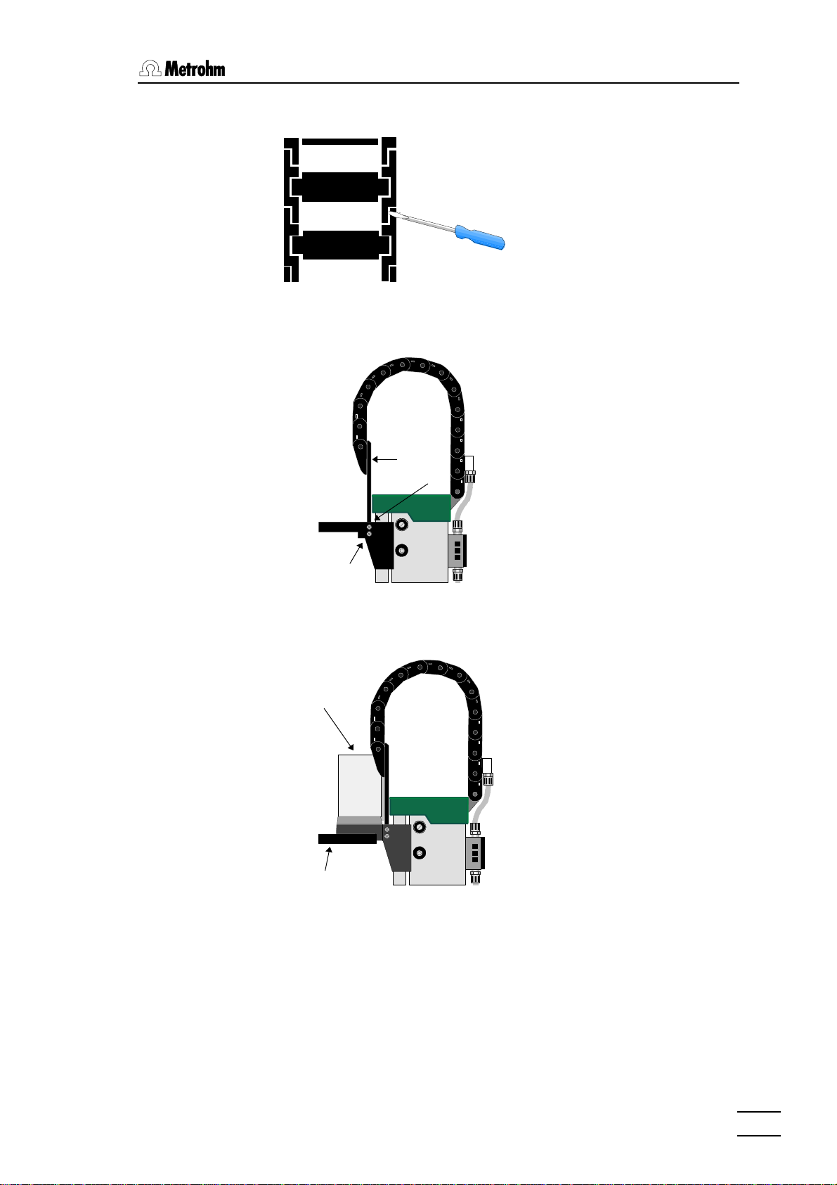
4.2 Installing the Swing Head
Disengage the guide chain
Use a screwdriver to open
the guide chain in-between
two links to facilitate the
process of disassembling the
titration head and installing
the swing head.
Connect the swing head to Tower 1
Loosen screws A on both
sides and remove the titration
head together with the
mounting plate and the
lowest link. Use an angled
C
B
screwdriver for recessedhead screws for 2-tower
sample changers. Then
loosen screws B and C and
connect the new mounting
plate for the swing head
A
(6.2058.000) to the bottom
link (screws C).
Before fixing the swing head to tower 1, rotate screws A a few
times in the appropriate holes to cut a thread into the plastic.
The swing head can now be
759 Swing
head
installed on the mounting
plate (screws B). Ensure that
the lead runs in the guide
chain. After screwing the
swing head and mounting
plate into place on the tower,
the bottom link is re-engaged
Titration or
transfer head
The splash protection supplied with the pipetting swing head
(2.759.0010) is connected to tower 2. The splash shield supplied
with the titration swing head (2.759.0020) is connected to tower 1
when used with the 2-tower model.
717 Sample Changer, Swing Head
17
Page 20

4.3 Accessories for the Titration Head
The 759 swing head can now be connected to the remote socket
of the sample changer (see page 12).
The configuration of the sample changer is carried out in the control instrument.
4.3 Accessories for the Titration Head
The titration head can be
fitted with a 722 Propeller Rod Stirrer, up to two
Micro electrodes, three
burette tips and three
spray nozzles.
722 Rod stirrer
2.722.0020
M6 spray nozzles
6.2740.020
M8 Thread stopper
4.658.0180
for Micro electrode or
burette tip
Micro electrode
Burette tips
M6 spray nozzle
6.2740.020
Stirring propeller
6.1909.030
M8 Aspiration tip
18
717 Sample Changer, Swing Head
Page 21

4.3 Accessories for the Titration Head
Aligning the titration/transfer head
The swing head executes a shift movement as it approaches the
sample vessels. It can adopt any of four fixed positions, depending
on which row is targeted, or whether the lift is in the shift position.
The titration or transfer head should be aligned in order to guarantee that the individual positions are approached with precision.
Place the sample rack that you wish to use on the sample changer
and insert a few sample vessels. Approach one sample position.
Slightly loosen the three screws securing the titration head to the
underside of the swing head and align the titration head so that
electrodes, stirrer, burette tip and tubes are centered in the sample vessel. Retighten the screws. Proceed in exactly the same way
for the transfer head.
717 Sample Changer, Swing Head
19
Page 22

5.1 Technical Specifications
5 AppendixAppendix
5.1 Technical Specifications
5.1.1 717 Sample Changer
Dimensions Height: 0.72 m, Width: 0.28 m, Depth: 0.48 m
Weight 15.5 kg (without accessories, 2-tower model)
10.0 kg (without accessories, 1-tower model)
Material Sample Changer case: metal case, multiple enameling
Lift path 235 mm
Lift Load: approx. 10 N
Stroke speed: adjustable, 3 – 25 mm/s
Turntable Turning speed:
adjustable, 3 – 20 angular degrees/s
Stirrer Stirring speed: adjustable to 15 levels
- Magnet stirrer 180/s – 2600/s
- Rod stirrer 180/s – 3000/s
Pump with Conveying capacity (manometric lift 2m):
Valve 0.33 L/min
20
717 Sample Changer, Appendix
Page 23
5.1 Technical Specifications
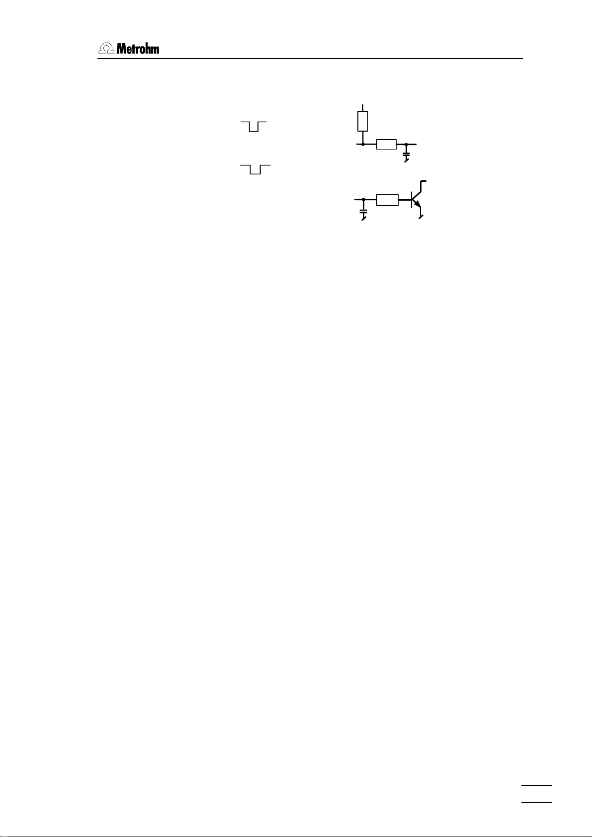
Remote Interface Programmable parallel interface for controlling external
instruments
+5V
t
p
Input:
Output:
t
>20 ms
p
t
p
t
>200 ms
p
V
= 40 V
CEO
active = low
inactive = high
active = low
inactive = high
IC = 20 mA
+5 V: Maximum charge = 20 mA
Temperatures Nominal functional range 5 – 40 °C
Transport and storage: –40 – +70°C
Distribution Connection to the External Bus of a Metrohm control device,
voltage e.g. 726 Titroprocessor, ...
All data are typical values with the exception of those specially marked.
Safety Specifications
Constructed and tested according to IEC 1010 / EN 61010 /
UL 3101-1, Safety Class III
Degree of protection IP 22
The instruction manual contains information and warnings which
the user should follow to guarantee the safe operation of the instrument.
Electromagnetic Compatibility (EMC)
Emitted Interference: The instrument complies with the basic specifications
EN 50081-1/2 1992, EN 55011 (class B), EN 55022
(class B), and NAMUR.
Interference immunity: The basic specifications EN 50082-1 1997, and IEC 801-2 to
IEC 801-4 are adhered to.
717 Sample Changer, Appendix
21
Page 24

5.1 Technical Specifications
5.1.2 759 Swing Head
Dimensions Height: 0.14 m, Width: 0.10 m, Depth: 0.09 m
Weight 0.63 kg
Material Swing Head case: Polybuteneterephthalate (PBTP)
with metallic fiber
Titration Head: Polypropylene
Rotation 4 fix positions
Temperatures Nominal functional range 5 – 40 °C
Transport and storage –40 – +70 °C
Distribution 5 V DC, drawing of current 500 mA
voltage connection to the remote socket of the Metrohm Sample
Changers, e.g. model 717, 730, 760, ...
All data are typical values.
Safety Specifications
Constructed and tested according to IEC 1010 / EN 61010 /
UL 3101-1, Safety Class III
Degree of protection IP 43
Electromagnetic Compatibility (EMC)
Emitted Interference: The instrument complies with the basic specifications
EN 50081-1/2 1992, EN 55011 (class B), EN 55022
(class B), and NAMUR.
Interference immunity: The basic specifications EN 50082-1 1997, and IEC 801-2 to
IEC 801-6 are adhered to.
22
717 Sample Changer, Appendix
Page 25

5.2 Servicing and Maintenance
5.2.1 Servicing
The maintenance of the 717 Sample Changer should include a
yearly service check carried out by a specialist from Metrohm. If
caustic or corrosive chemicals are frequently used, shorter time
intervals between service checks can be necessary.
The Metrohm Service Department can offer technical advice regarding servicing and maintenance of all Metrohm instruments at
any time.
5.2.2 Maintenance / Attendance
Not only do highly sensitive measuring instruments require proper
care, a sample changer also requires this. Serious contaminations
can lead to functional disorders and a shortened life-span of the
rugged mechanics and electronics of the sample changer.
5.2 Servicing and Maintenance
Heavy soiling of the titration heads can influence the results of
measurements. Regular cleaning of exposed parts can prevent
this for the most part.
Chemical or solvent spills should be cleaned up immediately. The
connectors (in particular the power supply) should be protected
from contamination. The sample changer should never be operated without the covering foreseen for this purpose.
If corrosive media has entered the inside of the instrument, the
power plug has to be disconnected immediately to avoid massive
damage to the instruments electronic components. In case of such
damage, the Metrohm service personnel should be notified.
The instrument should not be opened by untrained personnel.
717 Sample Changer, Appendix
23
Page 26

5.3 Warranty and Conformity
5.3 Warranty and ConformityWarranty and Conformity
5.3.1 Warranty
The warranty on our products is limited to defects that are traceable to material, construction or manufacturing error which occur
within 12 months from the day of delivery. In this case, the defects
will be rectified in our workshops free of charge. Transport costs
are to be paid by the customer.
For day and night operation, the warranty is limited to 6 months.
Glass breakage in the case of electrodes or other parts is not cov-
ered by the warranty. Checks which are not a result of material or
manufacturing faults are also charged during the warranty period.
For parts of outside manufacture insofar as these constitute an
appreciable part of our instrument, the warranty stipulations of the
manufacturer in question apply.
With the regard to the guarantee of accuracy, the technical specifications in the instruction manual are authoritative.
Concerning defects in material, construction or design as well as
the absence of guaranteed features, the orderer has no rights or
claims except those mentioned above.
If damage of the packaging is evident on receipt of a consignment
or if the goods show signs of transport damage after unpacking,
the carrier must be informed immediately and a written damage
report demanded. lack of an official damage report releases
Metrohm from any liability to pay compensation.
If any instruments and parts have to be returned, the original
packaging should be used if at all possible. This applies above all
to instruments, electrodes, burette cylinders and PTFE pistons.
Before embedment in wood shavings or similar material, the parts
must be packed in a dustproof package (for instruments, use of a
plastic bag is imperative). If open assemblies are enclosed in the
scope of delivery that are sensitive to electromagnetic voltages
(e.g. data interfaces etc.) these must be returned in the associated
original protective packaging (e.g. conductive protective bag).
(Exception: assemblies with built-in voltage source belong in a
non-conductive protective packaging). For damage which arises
as a result of non-compliance with these instructions, no warranty
responsibility whatsoever will be accepted by Metrohm.
24
717 Sample Changer, Appendix
Page 27

5.3 Warranty and Conformity
5.3.2 Certificate of Conformity and System Validation for the
717 Sample Changer
This is to certify the conformity to the standard specifications for electrical appliances and accessories, as well as to the standard specifications for
security and to system validation issued by the manufacturing company.
Name of commodity: 717 Sample Changer
Name of manufacturer: Metrohm Ltd., Herisau,
Switzerland
Principal technical information: Connection to the External Bus of a
Metrohm control device
This Metrohm instrument has been built and has undergone final type testing
according to the standards:
Electromagnetic compatibility
IEC 801-2 / level 3, IEC 801-3 / level 2, IEC 801-4 / level 3,
EN 55011 / class B, EN 55022 / class B, EN 50081-1/2 1992,
EN 50082-1 1997
Security specifications
IEC 1010, EN 61010, UL 3101-1
It has also been certified by the Swiss Electronical Association (SEV), which is
member of the International Certification Body (CB / IEC).
The technical specifications are documented in the instruction manual.
The system software, stored in Read Only Memories (ROMs) has been validated in connection with standard operating procedures in respect to functionality and performance. The features of the system software are documented in the instruction manual.
Metrohm Ltd. is holder of the SQS certificate of the quality system ISO 9001
for quality assurance in design/development, production, installation and
servicing.
Herisau, March 5, 1998
717 Sample Changer, Appendix
Dr. J. Frank Ch. Buchmann
Development Manager Production and
Quality Assurance Manager
25
Page 28

5.3 Warranty and Conformity
Ionenanalytik • Analyse des ions • Ion analysis • Análisis iónico
717 Sample Changer
EU Declaration of Conformity
The Metrohm AG company, Herisau, Switzerland hereby certifies that the instrument:
717 Sample Changer
meets the requirements of EU Directives 89/336/EWG and 73/23/EWG.
Source of specifications:
EN 50081 Electromagnetic compatibility, basic specification Emitted Interference
EN 50082-1 Electromagnetic compatibility, basic specification Interference Immunity
EN 61010 Safety requirements for electrical laboratory measurement and control
equipment
Description of the instrument:
Sample changer for the automation of batch processing of larger sample series, applying titration, dosing and measuring methods in laboratory and industry.
Herisau, March 5, 1998
26
Dr. J. Frank Ch. Buchmann
Development Manager Production and
Quality Assurance Manager
717 Sample Changer, Appendix
Page 29

5.3 Warranty and Conformity
5.3.3 Certificate of Conformity and System Validation for the
759 Swing Head
This is to certify the conformity to the standard specifications for electrical appliances and accessories, as well as to the standard specifications for
security and to system validation issued by the manufacturing company.
Name of commodity: 759 Swing Head
Name of manufacturer: Metrohm Ltd., Herisau,
Switzerland
Principal technical information: Distribution voltage: 5 V DC
Drawing of Currency: 500 mA
This Metrohm instrument has been built and has undergone final type testing
according to the standards:
Electromagnetic compatibility
IEC 801-2 / level 4, IEC 801-3 / level 2, IEC 801-4 / level 3,
IEC 801-5 / level 3, IEC 801-6 / level 2, EN 55011 / class B,
EN 55022 / class B, EN 50081-1/2 1992, EN 50082-1 1997
Security specifications
IEC 1010, EN61010, UL 3101-1
The technical specifications are documented in the instruction manual.
Metrohm Ltd. is holder of the SQS certificate of the quality system ISO 9001
for quality assurance in design/development, production, installation and
servicing.
Herisau, Oct. 23, 1997
Dr. J. Frank Ch. Buchmann
Development Manager Production and
Quality Assurance Manager
717 Sample Changer, Appendix
27
Page 30

5.3 Warranty and Conformity
Ionenanalytik • Analyse des ions • Ion analysis • Análisis iónico
759 Swing Head
EU Declaration of Conformity
The Metrohm AG company, Herisau, Switzerland hereby certifies that the instrument:
759 Swing Head
meets the requirements of EU Directives 89/336/EWG and 73/23/EWG.
Source of specifications:
EN 50081 Electromagnetic compatibility, basic specification Emitted Interference
EN 50082-1 Electromagnetic compatibility, basic specification Interference Immunity
EN 61010 Safety requirements for electrical laboratory measurement and control
equipment
Description of the instrument:
The Swing head is an accessory to the Metrohm sample changers 717, 730 and 760
for the automation of batch processing of larger sample series in chemical analytics.
Herisau, Oct. 23, 1997
28
Dr. J. Frank Ch. Buchmann
Development Manager Production and
Quality Assurance Manager
717 Sample Changer, Appendix
Page 31

5.4 AccessoriesAccessories
Sample Changer with 1 Tower and 1 Pump 2.717.0010
includes the following accessories:
SGJ14 sleeve 2 6.1236.020
SGJ14 plastic stopper 5 6.1446.000
SGJ9 stopper 3 6.1446.010
M6 thread stopper 6.1446.040
PE canister 10 liter 6.1621.000
FEP tubing connector M6 80 6.1805.110
PTFE tubing 4 meter 4/6 6.1812.000
Guiding shaft 6.1823.000
Connector for canister 6.1828.000
Fixing clip 10x 6.2053.000
Bushing 3 6.2709.070
Rotating nozzle 6.2740.000
Splash protection 6.2751.010
Plug cover 6.2752.010
External Bus cable DB 37-pol 6.2135.000
Instructions for Use for 717 Sample Changer 8.717.1003
5.4 Accessories
Pieces
Sample Changer with 1 Tower and 2 Pumps 2.717.0020
includes the following accessories:
Pieces
SGJ14 sleeve 2 6.1236.020
SGJ14 plastic stopper 5 6.1446.000
SGJ9 stopper 3 6.1446.010
M6 thread stopper 6.1446.040
SGJ14 stopper 6,4 mm 6.1446.160
M8 aspiration tip 6.1543.170
PE canister 10 liter 2 6.1621.000
FEP tubing connector M6 80 6.1805.110
FEP tubing connector M6 48 6.1805.420
PTFE tubing connector M8 60 6.1805.510
PTFE tubing 4 meter 4/6 2 6.1812.000
M8 screw connector 4/6 mm / M8 6.1820.030
Connector for canister 2 6.1828.000
Clip for burette tip 6.2042.020
Fixing clip 10x 6.2053.000
Bushing 3 6.2709.070
M6 spray nozzle 3 6.2740.020
Splash protection 6.2751.010
Plug cover 6.2752.010
External Bus cable DB 37-pol 6.2135.000
Instructions for Use for 717 Sample Changer 8.717.1003
717 Sample Changer, Appendix
29
Page 32

5.4 Accessories
Sample Changer with 1 Tower without Pumps 2.717.0030
includes the following accessories:
Pieces
SGJ14 sleeve 2 6.1236.020
FEP tubing connector M6 80 6.1805.110
Bushing 3 6.2709.070
Splash protection 6.2751.010
Plug cover 6.2752.010
External Bus cable DB 37-pol 6.2135.000
Instructions for Use for 717 Sample Changer 8.717.1003
Sample Changer with 2 Towers and 2 Pumps 2.717.0110
includes following accessories
Pieces
SGJ14 sleeve 4 6.1236.020
SGJ14 plastic stopper 10 6.1446.000
SGJ9 stopper 6 6.1446.010
M6 thread stopper 2 6.1446.040
PE canister 10 liter 2 6.1621.000
FEP tubing connector M6 80 2 6.1805.110
PTFE tubing 4 meter 4/6 2 6.1812.000
Guiding shaft 2 6.1823.000
Connector for canister 2 6.1828.000
Fixing clip 10x 2 6.2053.000
Bushing 6 6.2709.070
Rotating nozzle 2 6.2740.000
Splash protection 6.2751.020
Plug cover 6.2752.010
External Bus cable DB 37-pol 6.2135.000
Instructions for Use for 717 Sample Changer 8.717.1003
30
Sample Changer with 2 Towers and 4 Pumps 2.717.0120
includes the following accessories:
Pieces
SGJ14 sleeve 4 6.1236.020
SGJ14 plastic stopper 10 6.1446.000
SGJ9 stopper 6 6.1446.010
M6 thread stopper 2 6.1446.040
SGJ14 stopper 6,4 mm 2 6.1446.160
M8 aspiration tip 2 6.1543.170
PE canister 10 liter 4 6.1621.000
FEP tubing connector M6 80 2 6.1805.110
FEP tubing connector M6 48 6 6.1805.420
PTFE tubing connector M8 60 2 6.1805.510
PTFE tubing 4 meter 4/6 4 6.1812.000
M8 screw connector 4/6 mm / M8 2 6.1820.030
Connector for canister 4 6.1828.000
717 Sample Changer, Appendix
Page 33

5.4 Accessories
Clip for burette tip 2 6.2042.020
Fixing clip 10x 2 6.2053.000
Bushing 6 6.2709.070
M6 Spray nozzle 6 6.2740.020
Splash protection 6.2751.020
Plug cover 6.2752.010
External Bus cable DB 37-pol 6.2135.000
Instructions for Use for 717 Sample Changer 8.717.1003
Sample Changer with 2 Towers without Pumps 2.717.0130
includes the following accessories:
Pieces
SGJ14 sleeve 4 6.1236.020
FEP tubing connector M6 80 2 6.1805.110
Bushing 6 6.2709.070
Splash protection 6.2751.010
Plug cover 6.2752.010
External Bus cable DB 37-pol 6.2135.000
Instructions for Use for 717 Sample Changer 8.717.1003
Options
Accessories to separate order at additional charge:
722 Rod stirrer for the sample changer
Rod stirrer 2.722.0020
Stirrer propeller PP (104 mm) 6.1909.020
741 Magnetic stirrer
Magnetic stirrer 2.741.0010
Macro Titration head (6x NS14, 3x NS9) 6.1458.010
Micro Titration head (4x M10) 6.1458.020
759 Swing Head with Transfer Head 2.759.0010
includes the following accessories:
Transfer head 6.1462.010
Pipetting tube 10 mL (length 3.8 m, 6.1562.100
inner diameter 2.0 mm)
Guiding shaft for pipetting tube 6.1823.010
Holding plate for the swing head 6.2058.000
Splash protection for tower 2 6.2751.010
717 Sample Changer, Appendix
31
Page 34

5.4 Accessories
759 Swing Head with Titration Head 2.759.0020
includes the following accessories:
Pieces
Titration head 6.1462.020
Stirrer propeller PP (104 mm) for 75 mL vessels 6.1909.030
Clip for burette tip 2 6.2042.030
Holding plate for the swing head 6.2058.000
Splash protection for swing head 6.2751.030
Sample racks and beakers
Rack 12x 250 mL M12-0 *) 6.2041.310
Metrohm glass beaker 250 mL 6.1432.320
Metrohm PP beaker 200 mL 6.1453.220
Metrohm PP beaker 250 mL 6.1453.250
Rack 12x 150 mL M12-0 *) 6.2041.360
for standard glass beaker 150 mL (narrow) or
disposable beaker (Euro) PP 200 mL (1000 pcs.)6.1459.310
Rack14x 200 mL M14-0 6.2041.370
for disposable beaker (Euro) PP 200 mL 6.1459.310
Rack14x 8 oz M14-0 6.2041.380
for disposable beaker (US) PP 8 oz
Rack 16x 150 mL M16-0 6.2041.320
for standard glass beaker (narrow)
Rack 16x 120 mL M16-0 6.2041.390
for disposable beaker (US) 120 mL
Rack 24x 75 mL M24-0 *) 6.2041.340
(with Micro titration head only)
Metrohm glass beaker 75 mL 6.1432.210
32
*) Parallel processing at 2 towers possible
For operation with the 759 Swing Head:
Rack 48x 75 mL M48-1 6.2041.350
for direct titration
Metrohm glass beaker 75 mL 6.1432.210
Rack 126 x 15 mL and 2 x 250 mL M128-2 6.2041.400
for pipetting
for test tubes 15 mL and
Metrohm glass beaker 250 mL 6.1432.320
Metrohm PP beaker 200 mL 6.1453.220
Metrohm PP beaker 250 mL 6.1453.250
717 Sample Changer, Appendix
Page 35

5.4 Accessories
Electrodes for Sample Changer
It is recommended to use Longlife-Electrodes (LL) or titrodes
(without polished glass surface) with the SGJ sleeve SGJ14/12mm
6.1236.040 made of silicon caout-chouc for titrations with the
Macro Titration head.
The following special micro electrodes can be used with the Micro
Titration head and the 759 Swing Head for direct titration.
Comb. micro-pH-electrode (LL) 16 cm 6.0234.110
Micro reference electrode Ag/AgCl 16 cm 6.0736.110
Micro glass electrode 16 cm 6.0134.110
Micro-Ag titrode 16 cm 6.0433.110
Micro-Pt titrode 16 cm 6.0434.110
Micro-Au titrode 16 cm 6.0435.110
Pt 1000 temperature sensor 16 cm 6.1110.110
Dosing Instruments
685 Dosimat 2.685.0010
Exchange Unit with ceramic stopcock 1 mL 6.3013.113
5 mL 6.3013.153
10 mL 6.3013.213
20 mL 6.3013.223
50 mL 6.3013.253
Exchange Unit with PTFE stopcock 1 mL 6.3014.113
5 mL 6.3014.153
10 mL 6.3014.213
20 mL 6.3014.223
50 mL 6.3014.253
700 Dosino 2.700.0010
Dosing unit for Dosino 2 mL 6.3030.120
5 mL 6.3030.150
10 mL 6.3030.210
20 mL 6.3030.220
50 mL 6.3030.250
717 Sample Changer, Appendix
729 Dosimat Interface 2.729.0010
33
Page 36

5.5 Index
5.5 Index
A
Accessories ....................... 7, 29
Address ............................. 3, 13
Aligning .................................. 19
Appendix ................................ 20
Aspiration tip .................... 10, 18
Attendance ............................ 23
B
Beaker ............................. 14, 32
indicator ............................... 3
test ...................................... 3
Burette tip ........................ 10, 18
C
Cables ............................. 11, 12
CE .................................... 26, 28
Certificate ........................ 25, 27
Chemical resistance ................ 8
Code .................................. 3, 14
Conformity ....................... 25, 27
Connections ...... 7, 11,12, 13, 17
Connectors ...................... 1, 2, 3
Control ..................................... 5
D
Diaphragm pump ..................... 8
Distribution head .................. 1, 2
Dosimat ........................... 13, 33
Dosimat Interface ............ 13, 33
Dosing instruments .......... 13, 33
Dosino ............................. 13, 33
E
Electrodes ........................ 10, 33
Electromagnetic compatibility ....
..................................... 21, 22
Emitted interference ........ 21, 22
EU Declaration of Conformity ....
..................................... 26, 28
External Bus
address ......................... 3, 13
connections ....................... 13
socket .................................. 3
F
Failure ...................................... 6
G
Guide chain ........... 1, 2, 7, 8, 17
I
Infrared sensor ........................ 3
Initialize ................................... 3
Input ...................................... 11
Installation ......................... 5, 16
Interference immunity ...... 21, 22
ISO 9001 ......................... 25, 27
L
Lift ............................................ 1
Lines ...................................... 11
M
Magnet holder ......................... 9
Magnetic
code .................... 3, 9, 14, 15
rack code indicator .............. 3
sensor ............................. 3, 9
stirrer ............................. 8, 31
Maintenance .......................... 23
Manufacturing number ............. 3
Micro electrodes ........ 10, 18, 33
Models ......................... 4, 16, 29
Mounting .................. 7, 8, 10, 17
O
Options .................................. 31
Output .................................... 11
Overview ................................. 1
P
Packaging ................................ 5
Peripheral instruments 6, 11, 12
Pin assignment ...................... 11
Pipetting .......................... 16, 31
Plug cover ........................... 1, 2
Position table ......................... 14
Pump ........................... 1, 2, 4, 7
Pump head .............................. 8
R
Rack .......... 1, 3, 8, 9, 14, 16, 32
code .................................... 3
recognition ................ 3, 9, 14
Rear view ............................ 2, 3
Remote connections .............. 11
Remote Interface ......... 2, 11, 14
Rinsing equipment ................... 7
Rod magnets ......................... 14
Rod stirrer .................. 10, 18, 31
Rotating nozzle .................. 7, 10
S
Safety considerations ...........1, 6
Safety specifications ........21, 22
Sample
rack ........1, 3, 8, 9, 14, 16, 32
vessel .....................14, 16, 32
Sensors ....................................3
Servicing .................................23
Setting up .................5, 7, 10, 18
Side view ..............................1, 2
Signals ....................................11
Special beaker ........................16
Splash protection ..................1, 2
Spray nozzles .................7, 8, 18
Stirrer
connections ......................2, 4
propeller .......................10, 18
rail ....................................1, 8
Swing Head.................................
..............12, 16, 22, 27, 31, 32
installation ..........................16
System validation .............25, 27
T
Technical Specifications ...20, 22
Titration head .............................
..........7, 10, 16, 18, 19, 31, 32
vessel .................................16
Titroprocessor ........................13
Tower ...................................1, 4
Transfer head .............16, 19, 31
Tubing ..................................7, 8
Turntable ................................14
V
Valve ....................................1, 2
W
Warranty .................................24
34
717 Sample Changer, Appendix
 Loading...