

Page 1
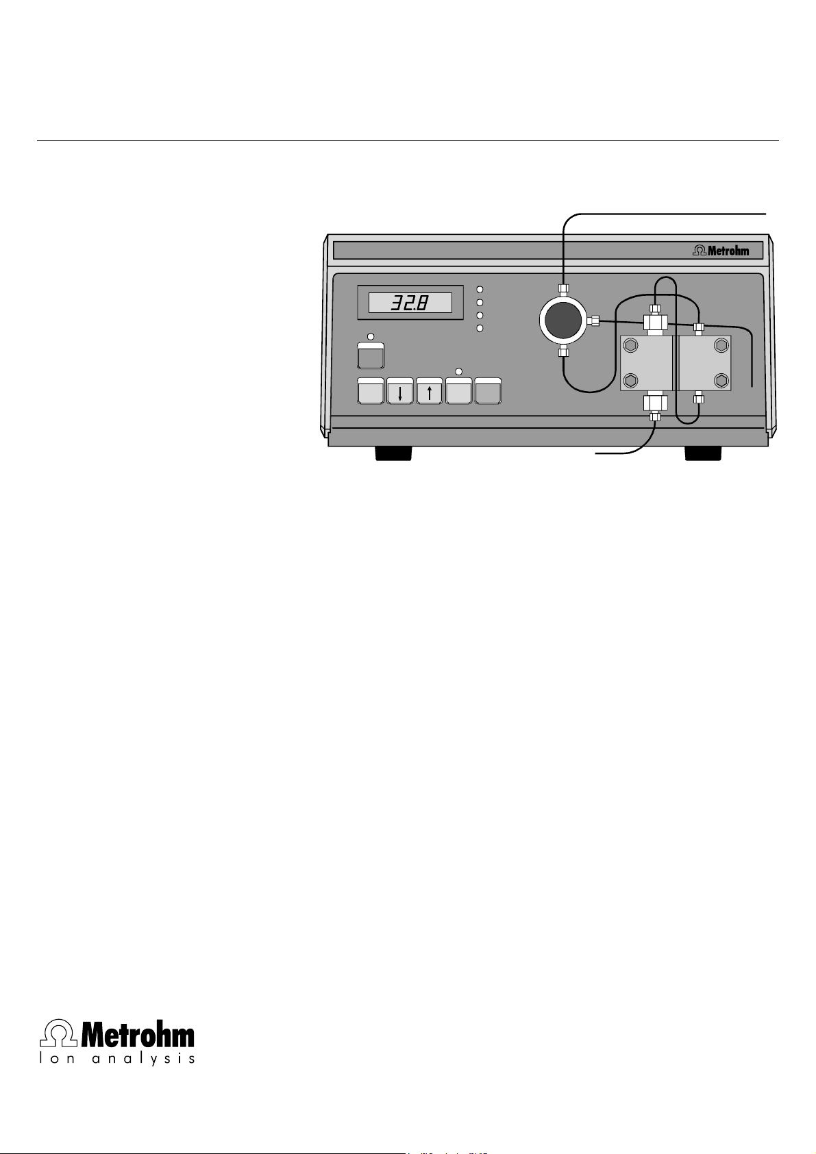
709 IC Pump
IC Pump709
FLOW
P
min
P
max
P
actual
R/S
SELECT EXT. PURGE
METROHM Ltd.
CH-9101 Herisau
Instructions for Use
8.709.1033
Page 2

Page 3
CH-9101 Herisau/Switzerland
Phone ++41 71 353 85 85
Fax ++41 71 353 89 01
CompuServe 100031,3703
Internet http://www.metrohm.com
E-Mail sales@metrohm.ch
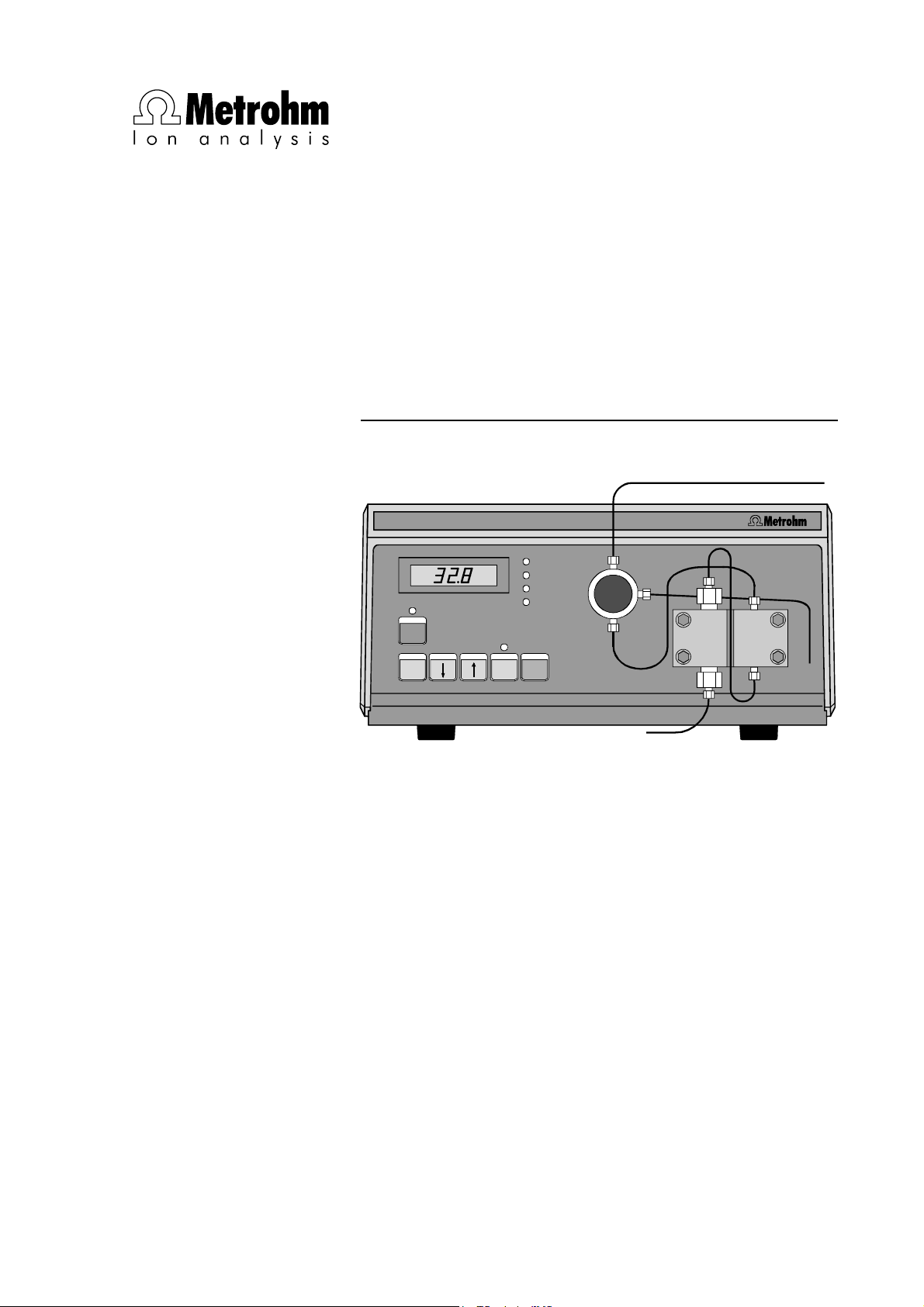
709 IC Pump
IC Pump709
FLOW
P
min
P
max
P
actual
R/S
SELECT EXT. PURGE
8.709.1033 Instructions for Use
16.10.2003 / chs
Page 4

Page 5

Table of contents
Table of contents
1 Introduction ..................................................................................... 1
1.1 Instrument description.................................................................... 1
1.2 Parts and controls ........................................................................... 2
1.3 Information about the Instructions for Use.................................. 4
1.3.1 Organization........................................................................... 4
1.3.2 Notation and pictograms ....................................................... 5
1.4 Safety notes...................................................................................... 6
1.4.1 Electrical safety ......................................................................6
1.4.2 General safety rules ............................................................... 6
2 Installation........................................................................................ 7
2.1 Setting up the 709 IC Pump .......................................................... 7
2.1.1 Packaging .............................................................................. 7
2.1.2 Check ..................................................................................... 7
2.1.3 Location.................................................................................. 7
2.1.4 Arrangement of the instruments............................................. 7
2.2 Mounting the pump head ...............................................................8
2.3 Attaching the accessories.............................................................. 9
2.3.1 Capillaries............................................................................... 9
2.3.2 PEEK connectors ...................................................................9
2.3.3 Steel connectors .................................................................. 10
2.3.4 Pulsation dampener ............................................................. 10
2.3.5 Filter unit PEEK..................................................................... 11
2.3.6 Filter unit Manufit.................................................................. 12
2.4 Connecting the tubing ..................................................................13
2.4.1 Connection to injection valve with PEEK capillaries ............ 13
2.4.2 Connection to injection valve with steel capillaries .............. 14
2.4.3 Connection to eluent container ............................................ 15
2.5 Electrical connection ....................................................................15
709 IC Pump
2.6 Mains connection ..........................................................................16
2.6.1 Setting the mains voltage..................................................... 16
2.6.2 Fuses.................................................................................... 16
2.6.3 Mains cable and mains connection ..................................... 17
2.6.4 On/off switching of the instrument ....................................... 17
2.7 Deaerating the pump..................................................................... 18
I
Page 6

Table of contents
3 Operation ........................................................................................ 19
3.1 Sequence of operations ............................................................... 19
3.2 Flussrate......................................................................................... 20
3.3 Flow correction.............................................................................. 20
3.4 Pressure limit values for safety shutdown ................................ 21
3.4.1 Minimum pressure limit........................................................ 21
3.4.2 Maximum pressure limit....................................................... 22
3.5 Switching the pump drive on and off ......................................... 22
3.6 On/off switching of the external control .................................... 23
3.7 Inquiry of the current pressure ................................................... 23
3.8 Overview of the key functions..................................................... 23
4 Notes – Maintenance – Faults...................................... 25
4.1 Practical notes............................................................................... 25
4.1.1 Protection against foreign particles ..................................... 25
4.1.2 Pulsation dampener............................................................. 25
4.1.3 Eluents ................................................................................. 25
4.2 Maintenance and servicing.......................................................... 26
4.2.1 General information ............................................................. 26
4.2.2 Maintenance work at the pump head .................................. 27
4.3 Faults and malfunctions............................................................... 31
4.4 Diagnosis........................................................................................ 32
4.4.1 General information ............................................................. 32
4.4.2 Entry of diagnostics with automatic display test.................. 33
4.4.3 Keyboard test....................................................................... 33
4.4.4 RS232 Test........................................................................... 34
4.4.5 Initialize and test RAM.......................................................... 35
4.5 Validation / GLP............................................................................. 36
5 Interfaces ....................................................................................... 37
5.1 RS232 interface ............................................................................. 37
5.1.1 General rules for remote control .......................................... 37
5.1.2 Call-up of objects................................................................. 38
5.1.3 Trigger.................................................................................. 39
5.1.4 Status messages ................................................................. 40
5.1.5 Error messages.................................................................... 41
5.1.6 RS232 error rectification....................................................... 41
5.1.7 Remote control commands ................................................. 42
5.1.8 Data transmission protocol.................................................. 43
709 IC Pump
II
Page 7

Table of contents
5.1.9 Handshake ........................................................................... 43
5.1.10 Pin assignment................................................................... 44
5.1.11 Setting the baud rate.......................................................... 45
5.2 Control interface............................................................................ 46
5.2.1 Functions.............................................................................. 46
5.2.2 Settings for the control interface ..........................................46
5.2.3 Control inputs and outputs................................................... 47
6 Appendix ..........................................................................................49
6.1 Technical specifications............................................................... 49
6.2 Scope of delivery...........................................................................52
6.3 Optional accessories .................................................................... 54
6.4 Warranty and conformity .............................................................. 57
6.4.1 Warranty ............................................................................... 57
6.4.2 EU Declaration of conformity ...............................................58
6.4.3 Certificate of conformity and system validation ................... 59
6.5 Index................................................................................................ 60
List of figures
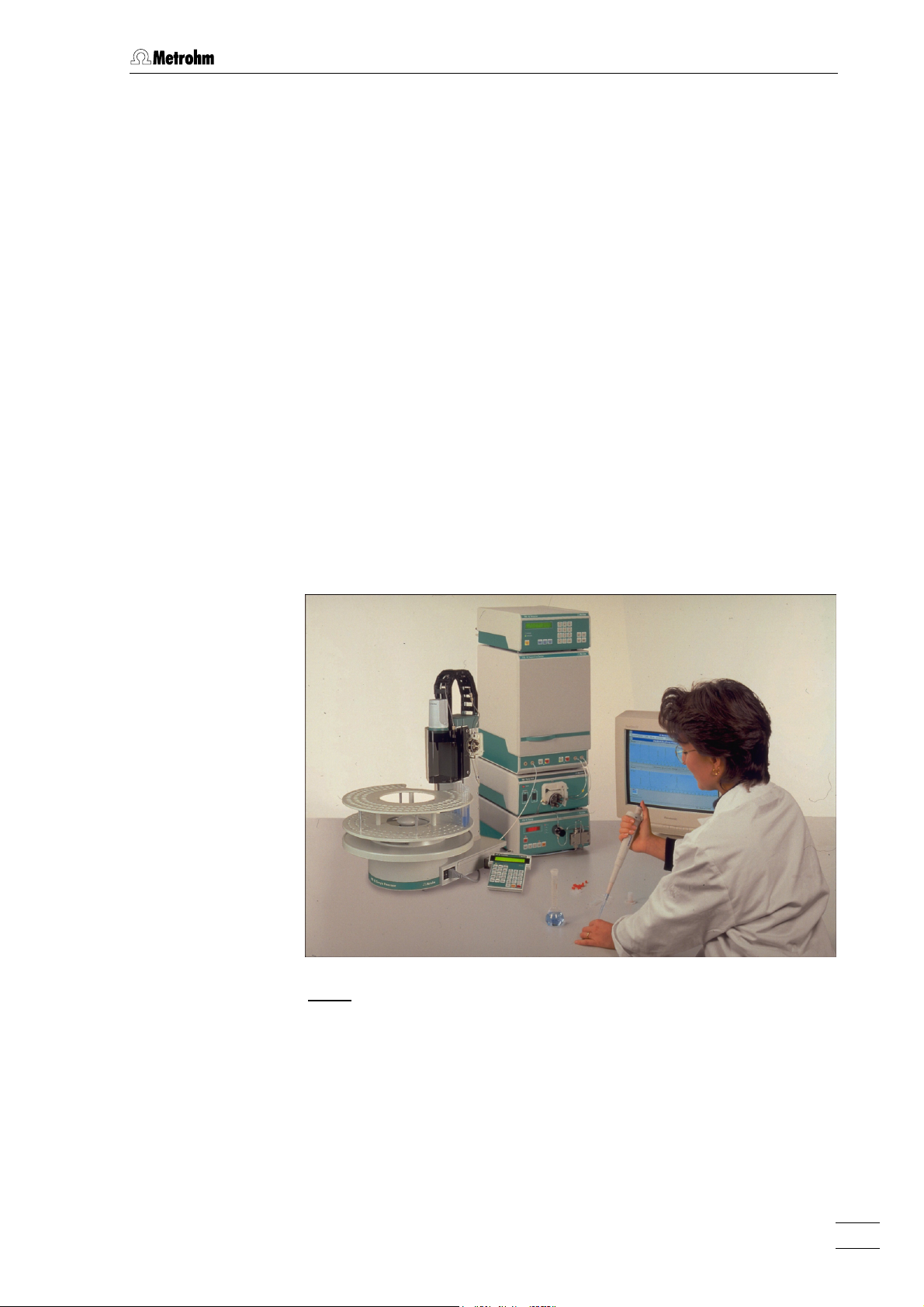
Fig. 1: IC system with 732 IC Detector, 733 IC Separation Center
and 766 IC Sample Processor .............................................................. 1
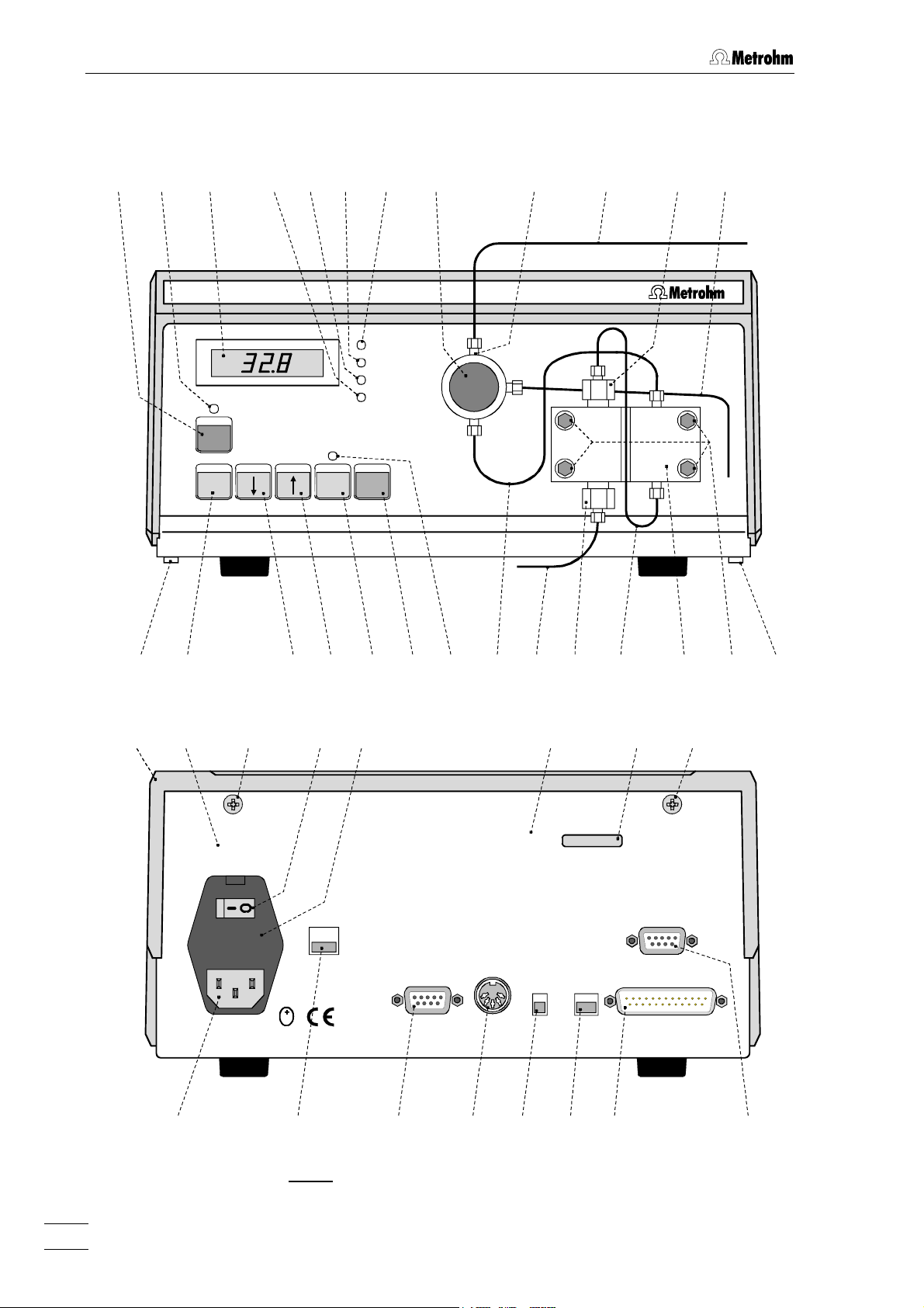
Fig. 2
: Front and rear of 709 IC Pump .............................................................2
Fig. 3
: Connectors for capillaries ..................................................................... 9
Fig. 4
: Filter unit PEEK (6.2821.100) .............................................................. 11
Fig. 5
: Filter unit Manufit (6.2821.000) ........................................................... 12
Fig. 6
: Connection to injection valve with PEEK capillaries ........................... 13
709 IC Pump
Fig. 7
: Connection to injection valve with steel capillaries............................. 14
Fig. 8
: Connection at 732 IC Detector............................................................ 15
Fig. 9
: Components of the pump head.......................................................... 28
Fig. 10
Fig. 11
: Replacement of the piston seal 67 ..................................................... 28
: Components of inlet valve 68 and outlet valve 69.............................. 30
III
Page 8

Table of contents
List of numbered parts and controls
1 Display .......................................... 2
2 LED "R/S"....................................... 2
3 Key <R/S> ................................... 2
4 Key <SELECT> ........................... 2
5 Key < ↓ >..................................... 2
6 Key < ↑ >..................................... 2
7 LED "Ext." ...................................... 2
8 Key <EXT.> ................................. 2
9 Key <PURGE> ............................ 2
10 LED "FLOW" .................................. 2
11 LED "P
12 LED "P
13 LED "P
"....................................... 2
min
" ...................................... 2
max
" .................................... 2
actual
14 Connection capillary ..................... 2
15 Aspirating capillary........................ 2
16 Inlet valve screw connection......... 2
17 Connection capillary ..................... 2
18 Pump head .............................. 2,28
19 Fastening screws .......................... 2
20 Outlet capillary .............................. 2
21 Outlet valve screw connection ...... 2
22 Connection capillary ................ 2,13
23 Connection.................................... 2
24 Purge valve ................................... 2
25 Screw ............................................ 2
26 Screw ............................................ 2
27 Housing cover............................... 2
28 Fuse data ...................................... 2
29 Mains switch ................................. 2
30 Fuse cover .................................... 2
31 Mains connection plug ................. 2
32 Mains voltage selectors ................ 2
33 Control interface............................ 2
34 Recorder output socket ................ 2
35 Sliding switch ................................ 2
36 Sliding switch ................................ 2
37 RS232 interface............................. 2
38 Current Loop interface .................. 2
39 Manufacturing number.................. 2
40 Instrument data ............................. 2
41 Ferrule........................................... 9
42 Pressure screw ............................. 9
43 Capillary ......................... 9,11,13,14
44 Compression fitting .................. 9,11
45 Connector ................................... 11
46 Housing for filter unit ................... 11
47 Connector ................................... 11
48 Inlet capillary .......................... 12,14
49 Manufit pressure screw............... 12
50 Counterpart end .......................... 12
51 PTFE gasket ................................ 12
52 Steel meshes .............................. 12
53 Steel mesh holding end .............. 12
54 Manufit housing .......................... 12
55 Outlet capillary ....................... 12,14
56 Filter unit PEEK ...................... 11,13
57 Pulsation dampener ............... 13,14
58 Filter unit Manufit.................... 12,14
59 Coupling...................................... 14
60 Screw .......................................... 28
61 Piston .......................................... 28
62 Spring retainer............................. 28
63 Spring.......................................... 28
64 Piston cartridge ........................... 28
65 Piston guide sleeve..................... 28
66 Sapphire supporting ring ............ 28
67 Piston guide sleeve ..................... 28
68 Piston seal................................... 28
69 Inlet valve ............................... 28,30
70 Outlet valve ............................ 28,30
71 Screw holder ............................... 28
72 Special tool ................................. 28
73 Special tool ................................. 28
74 Valve housing.............................. 30
75 Sealing ring ................................. 30
76 Sleeve.......................................... 30
77 Sapphire sleeve .......................... 30
78 Sapphire sphere.......................... 30
79 Ceramic holder............................ 30
80 Seal .............................................30
709 IC Pump
IV
Page 9
1.1 Instrument description
1 Introduction
1.1 Instrument description
The 709 IC Pump is a serial dual piston pump especially developed for
ion chromatography and optimized for use with Metrohm ion chromatographic instruments (e.g. 732 IC Detector and 733 IC Separation Center). The 709 IC Pump operates with minimal residual pulsation and has
an excellent flow constancy. In addition to the 2.709.0010 Standard
version with parts made of sapphire, ruby, ceramics, Kel-F, Teflon or
stainless steel, the totally metal free 2.709.0110 version is available.
All functions can be set simply at the front of the unit. The current and
entered data are indicated on the LED display. To assure optimum operational reliability, both lower and upper pressure limit values can be
set. If such a limit is reached, the pump switches itself off automatically.
An additional purge valve allows rapid removal of air from the pump
system.
709 IC Pump
Fig. 1
: IC system with 732 IC Detector, 733 IC Separation Center
and 766 IC Sample Processor
1
Page 10
1 Introduction
1.2 Parts and controls
3 1 13 24
2 12 11 10 23 22 21 20
IC Pump709
FLOW
P
min
P
max
P
actual
R/S
SELECT EXT. PURGE
45
28
Made by Metrohm Herisau Switzerland
26 2627
FUSE
230 V: 0,25 AT
115 V: 0,5 AT
S
6 8 9 7 14 15 1918171625 25
29
30 3940
WARNING - Risk of olectric shock - disconnect equ ipment from supply before opening.
230V
CONTROL
REC.
Type 1.709.
f=50-60 Hz
S=50 VA
TIME
CONST.
HIGH
LOW
CURRENT
LOOP
RS 232
CURRENT
LOOP
RS 232
31 32 33 34 38
Fig. 2
: Front and rear of 709 IC Pump
709 IC Pump
2
35 36 37
Page 11
1.2 Parts and controls
1 Display (LED)
2 LED "R/S"
Lights up when pump drive switched
on
3 Key <R/S> (Run/Stop)
On/off switching of the pump drive
4 Key <SELECT>
Switching display 1 to "Flow", "P
"P
max
" or "P
actual
"
5 Key < ↓ >
Continuous decrement of the displayed digital values
6 Key < ↑ >
Continuous increment of the displayed
digital values
7 LED "Ext."
Lights up when external control is
switched on
8 Key <EXT.>
On/off switching of external control via
RS232 or current loop interface
min
",
18 Pump head (6.2824.040/6.2824.100)
19 Fastening screws for pump head 18
20 Outlet capillary of purge valve
21 Outlet valve screw connection
22 Connection capillary to 733 IC
Separation Center
23 Attachment for connection capillary to
733 IC Separation Center
24 Purge valve
25 Screw for housing cover
26 Screw for housing cover
27 Housing cover
28 Fuse data
29 Mains switch
Switch for on/off switching of the unit:
I = ON 0 = OFF
30 Fuse cover
Changing the fuses, see section 2.6.2
9 Key <PURGE>
Deaeration of pump
10 LED "FLOW"
Lights up when flow rate is shown in
display 1
11 LED "P
min
"
Lights up when lower pressure limit
value for automatic shutoff of the
pump is shown in display 1
12 LED "P
max
"
Lights up when upper pressure limit
value for automatic shutoff of the
pump is shown in display 1
13 LED "P
actual
"
Lights up when current pressure is
shown in display 1
14 Connection capillary between purge
valve and pump head
15 Aspirating capillary
31 Mains connection plug
Mains connection see section 2.6
32 Mains voltage selector
115V: 100...120 V ± 10%
230V: 220...240 V ± 10%
33 Control interface
see section 5.2
34 Recorder output socket
Recorder output: 1 mV/MPa
35 Sliding switch "Time Constant"
Time constant for the recorder output:
HIGH ≈ 1 s; LOW ≈ 20 ms
36 Sliding switch for external control:
RS232 / Current Loop
37 RS232 interface
38 "Current Loop" interface
(details on request)
39 Manufacturing number
16 Inlet valve screw connection
17 Connection capillary
in pump head (integral)
709 IC Pump
40 Instrument data
Type number, mains frequency, power
consumption
3
Page 12

1 Introduction
1.3 Information about the Instructions for Use
Please read through these Instructions for Use carefully before
operating the 709 IC Pump. The Instructions for Use contain information and warnings to which the user must pay attention in order to
assure safe operation of the instrument.
1.3.1 Organization
These 8.709.1033 Instructions for Use for the 709 IC Pump provide a
comprehensive overview of the installation, startup procedure, operation, fault rectification and technical specifications of this instrument.
The Instructions for Use are organized as follows:
Section 1 Introduction
Description of the instrument, parts and controls,
safety notes
Section 2 Installation
Mounting the pump head, electrical connections,
tubing connections, mains connection
Section 3 Operation
Detailed description of operation,
explanation of all key functions
Section 4 Notes – Maintenance – Faults
Practical notes, maintenance, fault rectification,
diagnosis, validation
Section 5 Interfaces
Description of RS232 interface,
remote control language, control interface
Section 6 Appendix
Technical data, standard equipment, options,
warranty, declaration of conformity, index
To find the information you require about the instrument please use either the Table of contents or the Index at the back.
As a supplement to the Instructions for Use, the Metrohm Monograph
8.732.2003 "Ion chromatography" is also supplied. This provides an
introduction to the theoretical fundamentals and general information on
separating columns and sample pretreatment. You will find detailed information on the separating columns available from Metrohm and on
special IC applications in the relevant "Application Bulletins", which
are available on request free of charge from your Metrohm agency.
709 IC Pump
4
Page 13
1.3 Information about the Instructions for Use
1.3.2 Notation and pictograms
The following notations and pictograms (symbols) are used in these Instructions for Use:
<SELECT> Key
"0.0" Entry value
25 Part or control
(see section 1.2)
Hazard
This symbol draws attention to
a possible danger to life or
injury if the associated
directions are not followed
correctly.
Warning
This symbol draws attention to
possible damage to instruments or instrument parts if the
associated directions are not
followed correctly.
Caution
This symbol marks important
information. Read these directions before continuing.
Comment
This symbol marks additional
information and tips.
709 IC Pump
5
Page 14
1 Introduction
1.4 Safety notes
1.4.1 Electrical safety
While electrical safety in the handling of the 709 IC Pump is assured in
the context of the specifications IEC 1010-1 (protection class 1, degree
of protection IP40), the following points should be noted:
• Mains connection
Set the mains voltage and check the mains fuse and mains
connection in accordance with the instructions in section 2.6.
• Opening the 709 IC Pump
To avoid all danger of coming into contact with live components do
not open the instrument or remove any parts when the 709 IC Pump is
connected to the power supply. Always disconnect the instrument
from all voltage sources before you open it and ensure that the mains
cable is disconnected from mains connection plug 31 !
• Protection against static charges
Electronic components are sensitive to static charging and can be
destroyed by discharges. Before you touch any of the components
inside the 709 IC Pump, you should earth yourself and any tools you
are using by touching an earthed object (e.g. housing of the instrument or a radiator) to eliminate any static charges which exist.
1.4.2 General safety rules
• Handling of solvents
Check the pump tubing and all input and output leads periodically for
possible leaks. Follow the relevant instructions regarding the handling
of flammable and/or toxic solvents and their disposal.
709 IC Pump
6
Page 15
2.1 Setting up the 709 IC Pump
2 Installation
2.1 Setting up the 709 IC Pump
2.1.1 Packaging
The 709 IC Pump is supplied together with the separately packed
accessories in special packagings containing shock-absorbing foam
linings designed to provide excellent protection. The actual instrument
is packed in an evacuated polyethylene bag to prevent the ingress of
dust. Please store all these special packagings as only they assure
transport of the instruments free from damage.
2.1.2 Check
After receipt, immediately check whether the shipment is complete and
has arrived without damage (compare with delivery note and list of
accessories in section 6.2). In the case of transport damage, see
instructions in section 6.4.1 "Warranty".
2.1.3 Location
Position the 709 IC Pump in the laboratory at a location convenient for
operation, free from vibrations and protected against a corrosive atmosphere and contamination by chemicals.
To avoid disturbing temperature influences on the insulated column
compartment, the pump and eluent reservoir must be protected
against direct sunlight.
2.1.4 Arrangement of the instruments
In one-channel operation, the 709 IC Pump, 733 IC Separation Center
and 732 IC Detector are best stacked on top of one another in this order.
709 IC Pump
In two-channel operation (733.0X20 IC Separation Center), the optimum
arrangement (1, 2 or 3 towers) depends on the laboratory space available. However, the 709 IC Pumps should be set up at the very bottom
and the 732 IC Detectors at the very top.
7
Page 16
2 Installation
2.2 Mounting the pump head
To ensure that the pump drive is not damaged during transport a black
plastic block is mounted in place of the pump head on the right side of
the 709 IC Pump front panel. This transport safeguard block has to be
removed after undoing the four screws.
To avoid any damage to the pump head, the protective block must be
remounted if the pump has to be moved any great distance.
Next, the 6.2824.040 Pump Head 18 (6.2824.040 or 6.2824.100) with integrated piston units is unpacked and fixed in place of the transport
safeguard block with the four hexagon screws 19 as shown in Fig. 2.
To ensure that the pump head is not positioned wrongly, the holes at
the rear for the clamping bolts have different depths, i.e. 1 clamping
bolt is longer than the rest. The deepest hole must naturally accommodate the longest bolt. If this is not the case, the pump will not
function properly.
The connection capillary 14 fastened to purge valve 24 is screwed onto
pump head 18 as shown in Fig. 2.
The 2.709.0110 IC Pump MF (metal-free version) should only be
…
operated in the pressure range of 0
higher pressure, the 6.2824.100 PEEK pump head can be damaged.
So make sure that the maximum shutoff pressure
always set to
≤
25.0 MPa (see section 3.4.2).
25.0 MPa (0…250 bar). With
P
of the pump is
max
709 IC Pump
8
Page 17
2.3 Attaching the accessories
2.3 Attaching the accessories
2.3.1 Capillaries
Some of the connections under high pressure between the 709 IC
Pump and the IC system must be set up by the user. For the pressure
range 0…25 MPa (0…250 bar) the 6.1831.010 PEEK capillary
1
(i.d. = 0.25 mm, e.d. =
of the 709 IC Pump can be used for both pump versions. For the pressure range 25…50 MPa (250…500 bar), which is permissible only for
the not
(i.d. = 0.25 mm, e.d. =
With PEEK capillaries the connection is made preferably with the
6.2744.010 PEEK connectors (see section 2.3.2), with steel capillaries,
the 6.2620.000 and 6.2620.010 steel connectors should be used (see
section 2.3.3).
metal-free 2.709.0010 version, the 6.2620.020 Steel capillary
Capillaries fitted with new connectors must have a perfectly flat cut
surface. For PEEK capillaries it is best to use the 6.2621.080 Capil-
lary tubing cutter, for steel capillaries the 6.2621.040 Capillary
tubing cutter.
/16", length = 3 m) supplied in the accessories
1
/16", length = 3 m) must be used.
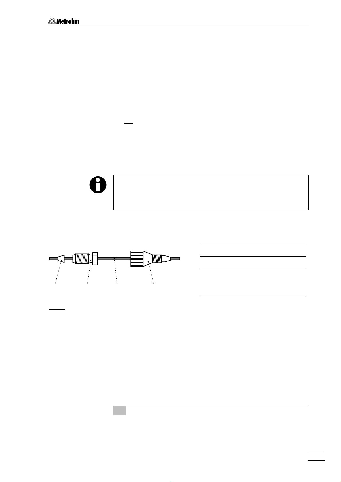
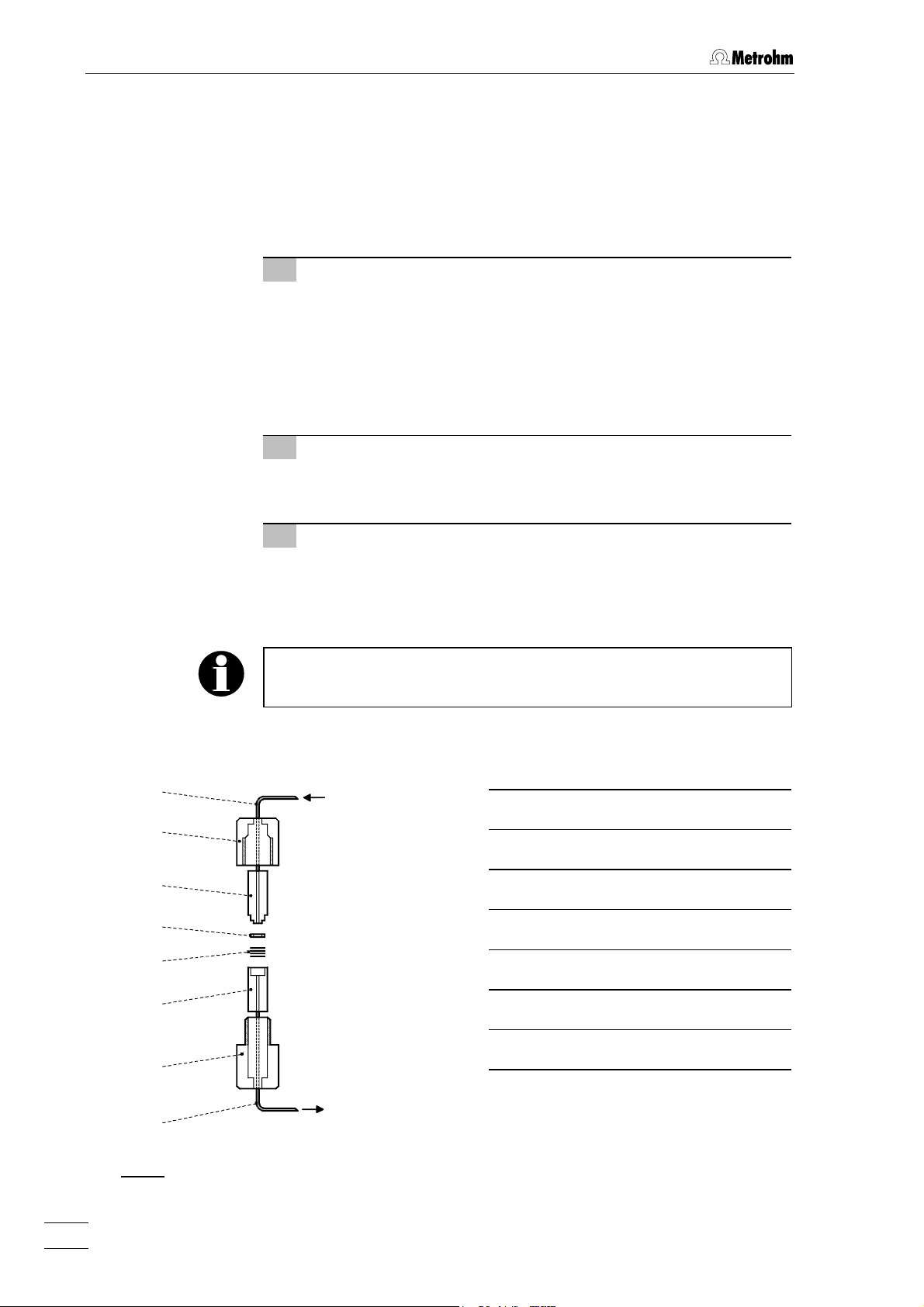
4241 43 44
: Connectors for capillaries
Fig. 3
2.3.2 PEEK connectors
41 Ferrule (6.2620.010)
42 Pressure screw (6.2620.000)
43 Capillary
6.2620.020 Steel capillary or
6.1831.010 PEEK capillary
44 Compression fitting
(6.2744.010)
709 IC Pump
For the connection of 6.1831.010 PEEK capillaries or of 6.1822.010
PTFE Microcapillaries (i.d. = 0.3 mm), the supplied 6.2744.010 PEEK
Compression fittings are used. It is best to proceed as follows:
1 Mount compression fitting
Slide a compression fitting 44 (6.2744.010) over the end of the
capillary 43 to be fastened as shown in Fig. 3.
9
Page 18
2 Installation
2 Insert capillary in connection
Push capillary end in the corresponding connection as far as it
will go (to avoid dead volume).
3 Tighten compression fitting
Tighten compression fitting 44 by hand (never use tools).
2.3.3 Steel connectors
For the connection of steel capillaries, the steel connectors 6.2620.010
Ferrule and 6.2620.000 Pressure screw available as an option are
used. Proceed as follows:
1 Mount connectors
Slide a pressure screw 42 (6.2620.000) and a ferrule 41
(6.2620.010) over the end of the capillary 43 to be fastened as
shown in Fig. 3.
2 Insert capillary in connection
Push capillary end into the corresponding connection as far as it
will go (to avoid dead volume).
3 Tighten pressure screw
Tighten pressure screw 42 with the open-end spanner 1/4"
(6.2621.010) supplied.
2.3.4 Pulsation dampener
To protect the column material against pressure drops caused by the
injector, the use of a pulsation dampener connected between the pump
and the injection valve of the 733 IC Separation Center is recommended. The optional 6.2620.150 Pulsation dampener MF is very
well suited to this purpose (see section 6.3).
The metal-free 6.2620.150 Pulsation dampener is supplied fully assembled and has two connections for capillaries, for which the connectors
supplied or two 6.2744.010 PEEK compression fittings can be used.
The flow direction is arbitrary. The pulsation dampener is positioned in
the interior of the 733 IC Separation Center on the base below the injection valve (see 732/733 Instructions for Use).
709 IC Pump
10
Page 19
2.3 Attaching the accessories
2.3.5 Filter unit PEEK
The 6.2821.100 Filter unit PEEK supplied (see Fig. 4) serves to avoid
contamination of the piston seals by abrasive particles and can be used
in the pressure range 0…25 MPa (0…250 bar). The filter unit consists of
the housing 46 and the two connectors 45 (with filter) and 47 (without
filter) to be screwed into the housing 46. For the connection of capillaries 43, PEEK compression fittings 44 (6.2744.010) must be used.
New connectors 45 with filter are available as an option with the ordering number 6.2821.110 (10 pieces).
For the connection of the filter unit, please note the flow direction
arrow printed on the housing.
43 44 45 46 47 44 43
Fig. 4
: Filter unit PEEK (6.2821.100)
43 Capillary
6.1831.010 PEEK capillary
44 Compression fitting (6.2744.010) 47 Connector without filter
45 Connector with filter (6.2824.110)
Part of 6.2824.100 Filter unit
46 Housing for filter unit
Part of 6.2824.100 Filter unit
Part of 6.2824.100 Filter unit
709 IC Pump
11
Page 20
2 Installation
2.3.6 Filter unit Manufit
The 6.2821.000 Filter unit Manufit available as an option (see section 6.3) serves to avoid contamination of the piston seals by abrasive
particles and can be used in the pressure range 0…50 MPa
(0…500 bar) together with steel capillaries. It is installed as follows (see
Fig. 5):
1 Prepare Manufit housing
• Insert outlet capillary 55 with steel mesh holding end 53 into
Manufit housing 54.
• Insert the 4 steel meshes 52 provided into the steel mesh
holding end 53.
• Press the PTFE gasket 51 into the steel mesh holding end
53.
2 Prepare Manufit pressure screw
• Insert inlet capillary 48 with counterpart end 50 into Manufit
pressure screw 49.
3 Assembly
• Fit the two capillary end pieces 50 and 53 together.
• Screw Manufit pressure screw 49 and Manufit housing 54
firmly together.
To replace contaminated steel meshes, proceed in the reverse order.
48
IC Pump
709
48 Inlet capillary
49
49 Manufit pressure screw
50
51
52
50 Counterpart end
51 PTFE gasket (6.2821.010)
52 4 Steel meshes (6.2821.020)
53
53 Steel mesh holding end
54 Manufit housing
54
IC Separation
55
Fig. 5
: Filter unit Manufit (6.2821.000)
709 IC Pump
12
Center 733
55 Outlet capillary
Page 21
2.4 Connecting the tubing
2.4 Connecting the tubing
2.4.1 Connection to injection valve with PEEK capillaries
For the pressure range 0…25 MPa (0…250 bar), it is recommended to
use 6.1831.010 PEEK capillaries, a 6.2620.150 Pulsation dampener
(see section 2.3.4), and a Filter unit PEEK (see section 2.3.5) to connect
the 709 IC Pump to the injection valve of the 733 IC Separation Center.
Proceed as follows:
1 Connection to 709 IC Pump
• Cut connection capillary 22 (6.1831.010 PEEK capillary) to
the required length and equip it with connectors.
• Attach connection capillary 22 to connection 23 of the 709 IC
Pump (see Fig. 2).
2 Connection of filter unit PEEK
• Attach the other end of connection capillary 22 at the connec-
tor 45 (with filter) of the filter unit 56 (see Fig. 6).
• Connect a PEEK capillary 43 cut to the required length and
equipped with connectors to the connector 47 of the filter unit
56.
3 Installation of the capillary in the IC Separation
Center
• Procedure, see 732/733 Instructions for Use, section 2.6.5.
4 Connection of the pulsation dampener
• Procedure, see 732/733 Instructions for Use, section 2.6.5.
5 Connection to the injection valve
• Procedure, see 732/733 Instructions for Use, section 2.6.5.
22 56 43
709
Fig. 6
: Connection to injection valve with PEEK capillaries
57 43
733
22 Connection capillary
6.1831.010 PEEK capillary
43 PEEK capillary (6.1831.010) 57 Pulsation dampener (6.2620.150)
709 IC Pump
56 Filter unit PEEK (6.2821.100)
13
Page 22

2 Installation
2.4.2 Connection to injection valve with steel capillaries
For the pressure range 25…50 MPa (250…500 bar), it is recommended
to use 6.2620.020 steel capillaries, a 6.2620.150 Pulsation dampener
(see section 2.3.4), and a Filter unit Manufit (see section 2.3.6) to connect the not metal-free
733 IC Separation Center. Proceed as follows:
1 Connection of filter unit Manufit
• Attach inlet capillary 48 of the filter unit Manufit 58 to connec-
tion 23 of the 709 IC Pump (see Fig. 2).
• Attach outlet capillary 55 of the filter unit Manufit 58 using a
coupling 59 to a steel capillary 43 cut to the required length
and equipped with connectors (see Fig. 7).
2 Installation of the capillary in the IC Separation
Center
• Procedure, see 732/733 Instructions for Use, section 2.6.5.
2.709.0010 IC Pump to the injection valve of the
43 Capillary
6.2620.020 Steel capillary
3 Connection of the pulsation dampener
• Procedure, see 732/733 Instructions for Use, section 2.6.5.
4 Connection to the injection valve
• Procedure, see 732/733 Instructions for Use, section 2.6.5.
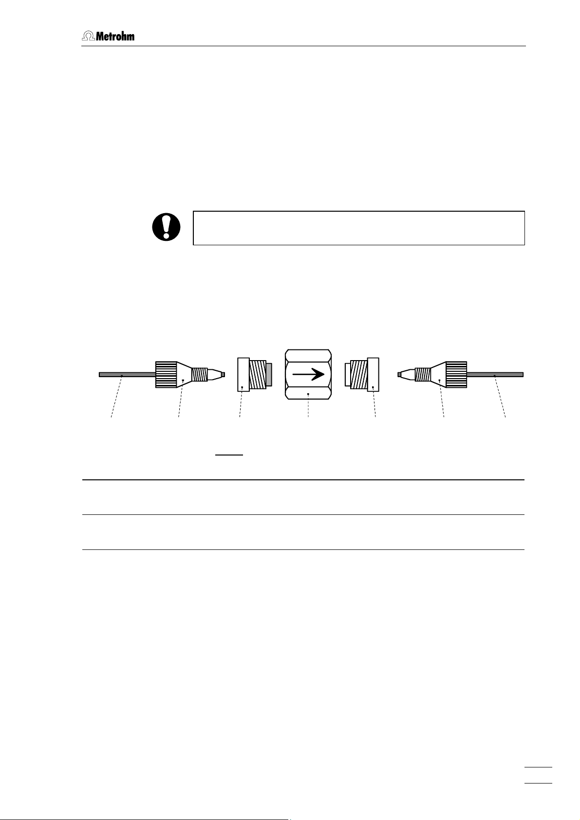
45 59 43
709
Fig. 7
: Connection to injection valve with steel capillaries
57 4358 52
733
57 Pulsation dampener (6.2620.150)
48 Inlet capillary
58 Filter unit Manufit (6.2824.000)
of filter unit Manufit 58
55 Outlet capillary
59 Coupling (6.2620.060)
of filter unit Manufit 58
709 IC Pump
14
Page 23

2.5 Electrical connection
2.4.3 Connection to eluent container
The 6.1834.000 Aspirating tubing (i.d. = 1.5 mm, e.d. = 2.5 mm, length
= 1.2 m) supplied is slid over the aspirating capillary 15. The
6.2821.090 Aspirating filter supplied is screwed onto the other end of
the tubing. The end of the tubing with the aspirating filter is then introduced in the eluent container.
Only degassed (with N
, He or vacuum) and microfiltered (0.45 µm
2
filter) eluents may be used!
It must be ensured that the eluent used is freely miscible with any
residual solvent in the pump head (the pump head is filled with
isopropanol or methanol/water in the factory). If this is not the case,
the pump must first be rinsed with a solvent that is miscible with both
the previous and subsequent eluent (e.g. acetone).
If you use the optional available 6.5324.000 Bottle rack, the
6.1834.010 Aspirating tubing (accessory of the bottle rack, length =
2.5 m) must be installed instead of the 6.1834.000 Aspirating tubing.
The end of the tubing with the screwed-on 6.2821.090 aspirating filter
is then fixed in the eluent vessel according to the instructions on the
leaflet supplied with the bottle rack.
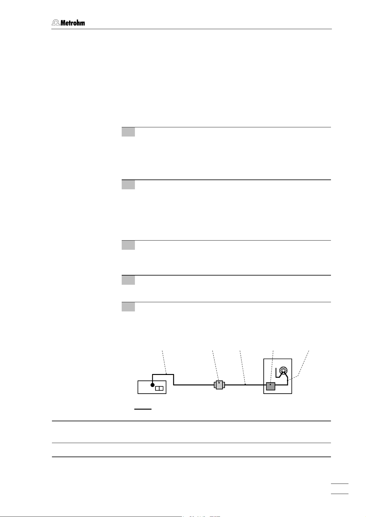
2.5 Electrical connection
The connection of the 709 IC Pump at the 732 IC Detector is made
acc. to Fig. 8 using the 6.2125.060 cable or another RS cable specified
as a "null modem" cable. To ensure proper functioning of the communication between the 732 IC Detector and 709 IC Pump, the sliding switch
36 on the IC pump must be set to "RS 232" and the external control
switched on with <EXT.> key 8 (see section 3.6).
732
709
Fig. 8
: Connection at 732 IC Detector
6.2125.060
709 IC Pump
15
Page 24

2 Installation
2.6 Mains connection
Follow the instructions below for connecting to the power supply. If
the instrument is operated with a mains voltage set wrongly and/or
wrong mains fuse, there is a danger of fire!
2.6.1 Setting the mains voltage
Before switching on the 709 IC Pump for the first time, check whether
the mains voltage set on the instrument (can be read in the mains voltage selector 32) matches the local mains voltage. If this is not the case,
you must switch the mains voltage by pushing the mains voltage selector 32 with a screwdriver:
Position of the mains
voltage selector 32:
230V
115V
230V: 220…240 V ± 10%
115V: 110…120 V ± 10%
2.6.2 Fuses
The 709 IC Pump contains two fuses built in as standard, either of type
0.25 AT (for 230 V: 0.25 A, slow-blow, Metrohm ordering number
U.600.0010) or 0.5 AT (for 110 V: 0.5 A, slow-blow, Metrohm ordering
number U.600.0013). Ensure that the two fuses correspond to the fuse
type specified for the local mains voltage (see fuse data 28). To change
wrong or blown fuses, proceed as follows:
Ensure that the instrument is never put into operation with fuses of
another type, otherwise there is danger of fire!
1 Disconnect mains cable
Disconnect mains cable from mains connection plug 31 of the
709 IC Pump.
2 Remove fuse cover
Using a screwdriver, lever out fuse cover 30 forwards until it
opens.
3 Check and change fuses if necessary
Carefully take the fuses installed for the desired mains voltage
out of the fuse holder and check its specifications:
100…120 V 0.5 A (slow-blow) Metrohm No. U.600.0013
220…240 V 0.25 A (slow-blow) Metrohm No. U.600.0010
Change fuse if necessary and reinsert in fuse holder.
709 IC Pump
16
Page 25

2.6 Mains connection
4 Install fuse holder
Reinsert fuse holders in the instrument (the arrows printed on the
holders must point in the same direction as the arrows on the
inside of fuse cover 30).
5 Install fuse cover
Push in fuse cover 30 firmly until it clicks into place.
6 Connect mains cable
Plug mains cable into mains connection plug 31.
2.6.3 Mains cable and mains connection
Mains cable
The instrument is supplied with one of three mains cables:
• 6.2122.020 with plug SEV 12 (Switzerland, …)
• 6.2122.040 with plug CEE(7), VII (Germany, …)
• 6.2133.070 with plug NEMA 5-15 (USA, …)
which are three-cored and fitted with a plug with an earthing pin. If a different plug has to be fitted, the yellow/green lead (IEC standard) must
be connected to protective earth (protection class 1).
Any break in the earthing inside or outside the instrument can make it
a hazard!
Mains connection
Plug the mains cable into mains connection plug 31 (see Fig. 2).
2.6.4 On/off switching of the instrument
The 709 IC Pump is switched on and off using mains switch 29. When
the instrument is switched on, all segments of display 1 and all LEDs
light up for a few seconds. The instrument is then in the standby mode
("ready" status).
709 IC Pump
17
Page 26

2 Installation
2.7 Deaerating the pump
The purge valve 24 is opened by turning anticlockwise and the pump
can now be deaerated by pressing the <PURGE> key 9.
The solvent bottle should be located somewhat above the pump, but at
least at the same level as the pump head 18 (never below the pump).
When the <PURGE> key is pressed the pump operates at the maximum flow rate (5 mL/min).
9
For safety reasons the <PURGE> key
mode of the pump, i.e. the <PURGE> key is disabled when the pump
is running in normal operation.
Should the pump not prime by itself, the 6.2816.020 syringe supplied is
used to siphon off solvent via the outlet capillary 20 with opened purge
valve through the pump head until there are no more bubbles in the
solvent entering the syringe. The pump can then again be purged
briefly by pressing the <PURGE> key 9.
functions only in the stop
On completion of this procedure, the purge valve 24 is closed by turning clockwise. The pump is now ready for operation.
709 IC Pump
18
Page 27

3.1 Sequence of operations
3 Operation
3.1 Sequence of operations
Installation
1. Setting up the pump Section 2.1
2. Mounting the pump head Section 2.2
3. Attaching the accessories Section 2.3
4. Tubing connections Section 2.4
5. Electrical connection Section 2.5
6. Mains connection Section 2.6
Startup procedure
1. Switching on the pump Section 2.6
2. Deaerating the pump Section 2.7
Settings
1. Setting the flow rate Section 3.2
2. Flow correction (option) Section 3.3
3. Setting the pressure limit
values Section 3.4
Switching on the pump drive
Switching off the pump drive
Section 3.5
Section 3.5
Standby mode
709 IC Pump
Switching off the pump
Section 2.6
19
Page 28

3 Operation
3.2 Flow rate
The flow rate can be set in the range of 0.05…5.00 mL/min with the
pump drive switched on or off as follows:
1 Select "FLOW"
Press <SELECT> key 4 until the "FLOW" LED 10 lights up.
2 Set flow rate
Press < ↓ > key 5 or < ↑ > key 6 until the desired flow rate (in
mL/min) appears in display 1.
3 Store flow rate
Release < ↓ > key 5 or < ↑ > key 6: the value shown in display
1 at the time of release will be stored.
3.3 Flow correction
Since the difference between displayed and actual flow rate can be
maximum 3 % owing to unavoidable tolerances in the manufacture of
mechanical parts, there is a possibility to adjust the 709 IC Pump after
installation of a new pump head. For this, a correction factor of 0.9…1.1
can be entered in the 709 IC Pump.
The correction factor is determined by measurement of the actual flow
rate with the aid of a measuring cylinder:
Correction factor =
In the entry of the correction factor, proceed as follows:
1 Select flow correction
Press <SELECT> key 4 for ca. 3 s until all LEDs (10...13) go out
and the correction factor appears in display 1.
2 Set flow correction
Press < ↓ > key 5 or < ↑ > key 6 until the desired flow correction appears in display 1.
Displayed flow rate (in mL/min)
Measured flow rate (in mL/min)
3 Store flow correction
Release < ↓ > key 5 or < ↑ > key 6: the value shown in display
1 at the time of release will be stored.
4 Return to standby mode
Press <SELECT> key 4 briefly, the pump is again in the
standby mode.
709 IC Pump
20
Page 29

3.4 Pressure limit values for safety shutdown
3.4 Pressure limit values for safety shutdown
3.4.1 Minimum pressure limit
The minimum shutoff pressure of the pump can be set in steps of
0.1 MPa from 0.1…50 MPa with the pump drive switched on or off. Proceed as follows:
1 Select "P
Press <SELECT> key 4 until the "P
min
"
" LED 11 lights up.
min
2 Set shutoff pressure
Press < ↓ > key 5 or < ↑ > key 6 until the desired minimum
shutoff pressure (in MPa) appears in display 1.
3 Store shutoff pressure
Release < ↓ > key 5 or < ↑ > key 6: the value shown in display
1 at the time of release will be stored.
Entry of the value "0.0" switches off the lower pressure limit monitoring.
The set limit value should lie far enough below the particular operating
pressure. If the pump pressure falls below this preset lower limit during
operation, the microprocessor checks whether this violation persists for
several revolutions of the cam or whether it was a temporary drop in
pressure due to an air bubble or a brief leak in the valves. If the cause is
a temporary loss of pressure, the pump is not switched off. In the case
of a pressure drop due to leaks or interrupted inflow of the eluent, the
pump drive is switched off and disabled.
If the pump has been shut off by the minimum pressure monitoring, the
LED 11 flashes, the shutoff pressure can be requested in the display
" (see section 3.7). The safety shutdown is not active during the
"P
actual
first two minutes after the pump drive has been switched on with the
<R/S> key 3.
709 IC Pump
Pressing the <R/S> key 3 re-enables the pump drive, the LED 11 no
longer flashes and the pump is in the standby mode. Pressing the
<R/S> key 3 again puts the pump back into operation.
21
Page 30

3 Operation
3.4.2 Maximum pressure limit
The maximum shutoff pressure of the pump can be set in steps of
0.1 MPa from 0.1…50 MPa with the pump drive switched on or off. Proceed as follows:
1 Select "P
Press <SELECT> key 4 until the "P
max
"
" LED 12 lights up.
max
2 Set shutoff pressure
Press < ↓ > key 5 or < ↑ > key 6 until the desired shutoff
pressure (in MPa) appears in display 1.
3 Store shutoff pressure
Release < ↓ > key 5 or < ↑ > key 6: the value shown in display
1 at the time of release will be stored.
The set limit value should lie between 5.0 and 10.0 MPa above the particular operating pressure or the maximum admissible operating pressure of the column. If the pump exceeds the preset limit value during
operation, the pump drive is switched off within 1 pump cycle and disabled. If the pump has been switched off by the maximum pressure
limit monitoring, the LED 12 flashes, the shutoff pressure can be requested in the display "P
" (see section. 3.7).
actual
Pressing the <R/S> key 3 re-enables the pump drive, LED 12 no
longer flashes and the pump is in the standby mode. Pressing the
<R/S> key 3 again puts the pump back into operation.
The 2.709.0110 IC Pump MF (metal-free version) should only be
…
operated in the pressure range of 0
higher pressure, the 6.2824.100 PEEK pump head can be damaged.
So make sure that the maximum shutoff pressure
≤
always set to
25.0 MPa.
25.0 MPa (0…250 bar). With
P
max
3.5 Switching the pump drive on and off
Switching on Pressing the <R/S> key 3 switches on the pump drive.
While the pump drive is running, LED 2 above the
<R/S> key 3 lights up.
Switching off To switch off the pump drive, press the <R/S> key 3
again. LED 2 goes out.
of the pump is
709 IC Pump
22
Page 31

3.6 On/off switching of the external control
3.6 On/off switching of the external control
Switching on Pressing the <EXT.> key 8 switches on the external
control. The interface (RS232, see section 5.1 or "Cur-
rent Loop", details on request) is selected with sliding
switch 36. With active external control the LED 7 above
the <EXT.> key 8 lights up. All keys with the exception
of <SELECT> 4 (selection of display function) are
blocked.
Switching off To switch off the external control, the <EXT.> key 8 is
pressed again. The LED 7 goes out and all functions
are once more accessible manually via the keypad.
3.7 Inquiry of the current pressure
The current pressure of the pump can be queried at any time when the
pump drive is switched on. Proceed as follows:
1 Select "P
Press <SELECT> key 4 until the "P
actual
"
actual
2 Read pressure
The current pressure (in MPa) is shown in display 1.
3.8 Overview of the key functions
On/off switching of the pump drive
R/S
When the pump drive is switched on, the LED above
the key is on.
" LED 13 lights up.
709 IC Pump
SELECT
Selecting the display function
FLOW Current flow rate in mL/min
Minimum shutoff pressure for automatic
P
min
Range: 0.01...5.00 mL/min
shutdown of the pump drive
Range: 0.1... 50 MPa (1...500 bar)
(P
min
< P
max
)
0.0: no shutoff
23
Page 32

3 Operation
Maximum shutoff pressure for automatic
P
max
shutdown of the pump drive
Range: 0.1...50 MPa (1...500 bar)
(P
P
Current pressure
actual
max
> P
min
)
NX Correction factor for flow rate (see
section 3.2). The <SELECT> key must
be pressed for ca. 3 s.
Range: 0.90 ... 1.10
Input key for continuous lowering of the value selected with the <SELECT> key. When the key is
released the current value is stored.
Pressing this key briefly changes the displayed value
by one digit, if the key is pressed longer the value is
changed continuously and increasingly faster.
PURGE
EXT.
Input key for continuous raising of the value selected
with the <SELECT> key. When the key is released
the current value is stored.
Pressing this key briefly changes the displayed value
by one digit, if the key is pressed longer the value is
changed continuously and increasingly faster.
On/off switching of the external control of the pump
via RS232 or current loop interface.
On/off switching of the maximum delivery rate
(5 mL/min) to purge the pump.
This key is active only in the standby mode.
709 IC Pump
24
Page 33

4.1 Practical notes
4 Notes – Maintenance – Faults
4.1 Practical notes
4.1.1 Protection against foreign particles
To protect the column against foreign particles which could have an
adverse influence on the separation efficiency, we advise you to subject
both the eluents and all samples to microfiltration (0.45 µm filter) and
to siphon the eluent through the 6.2821.090 Aspirating filter.
To avoid contamination by abrasive particles arising from piston seals
of the 709 IC Pump, it is advantageous to install an in-line filter between the pump and the 733 IC Separation Center. We recommend to
use either the 6.2821.100 Filter unit PEEK for the standard operation
with PEEK capillaries (see section 2.3.5) or the 6.2821.000 Filter unit
Manufit for the operation in the pressure range > 25.0 MPa
(> 250 bar) with steel capillaries (option, see section 2.3.6).
4.1.2 Pulsation dampener
To protect the column material against pressure shocks caused by injection we recommend to use a pulsation dampener between the 709
IC Pump and the 733 IC Separation Center. The optional 6.2620.150
Pulsation dampener MF (see section 2.3.4) is eminently suitable for
this purpose.
4.1.3 Eluents
Treatment
For the preparation of the eluents one should use chemicals of a purity
degree of at least "p.a.". For dilution please use only high purity water.
Fresh eluents should always be microfiltered (0.45 µm filter) and de-
gassed (with N
stirred with a magnetic stirrer, particularly when the recycling proce-
dure is employed or when alkaline eluents are used. For alkaline eluents and eluents with low buffering capacity one should preferably use
absorbers.
CO
2
, He or vacuum). The eluent should be continuously
2
709 IC Pump
The supply vessel containing the eluent must be closed as tightly as
possible to avoid excessive evaporation. This is primarily important with
eluents containing organic solvents (e.g. acetone), the evaporation of
which can lead to drifts in the long term. If work is performed in a very
sensitive range, even if one drop of condensate falls back in the eluent
this can cause a noticeable change in the background conductivity.
25
Page 34

4 Notes – Maintenance – Faults
Precipitates
Salt crystals between the piston and the seal are the cause of abrasive
particles, which can enter the eluent. These lead to contaminated
valves, pressure rise and in extreme cases to scratched pistons. It is
thus essential to ensure that no precipitates can appear, e.g. when
the eluent is changed. Solutions used in direct succession must therefore be miscible. If the system has to be rinsed with an organic solution,
several solvents with increasing or decreasing lipophilic character may
possibly have to be used (e.g. water ↔ acetone ↔ chloroform).
4.2 Maintenance and servicing
4.2.1 General information
Care
The 709 IC Pump requires proper care and attention. Excessive contamination of the instrument could possibly lead to malfunctions and a
shorter service life of the inherently rugged mechanical and electronic
parts.
Spilled chemicals and solvents should be wiped up immediately. It is
especially important to protect the plug connections at the rear of the
instrument (particular the mains plug) against contamination.
Although constructional measures have been designed to virtually
eliminate such a situation, should corrosive media penetrate the
interior of the instrument the mains plug of the 709 IC Pump must be
immediately disconnected to prevent extensive damage to the
instrument electronics. Inform Metrohm service if your instrument has
been damaged in such a way.
The instrument must not be opened by untrained personnel. Please
comply with the safety notes in section 1.4.1.
Maintenance by Metrohm service
Maintenance of the 709 IC Pump is best done as part of an annual service performed by specialists from the Metrohm company. If work is
frequently performed with caustic and corrosive chemicals, it may be
necessary to shorten the interval between servicing.
The Metrohm service department is always willing to offer expert advice
on the maintenance and servicing of all Metrohm instruments.
709 IC Pump
26
Page 35

4.2 Maintenance and servicing
4.2.2 Maintenance work at the pump head
In many cases, an unstable baseline (pulsation, flow fluctuations) can
be traced to contaminated valves or faulty, leaky piston seals. For
cleaning contaminated valves and/or replacement of wear parts such
as pistons, piston seals and valves, proceed as follows:
1 Detach pump head
Unscrew connection capillary 14 from the pump head 18 with
the aid of the ¼" wrench (see Fig. 2). Then remove the pump
head 18 from the pump housing by loosening the 4 hexagon
screws 19 using the 6.2621.030 hexagon key. The main piston is
on the left (when viewed from front), the auxiliary piston on the
right.
2 Disassemble pump head
Strip down pump head 18 in accordance with Fig. 9. Main and
auxiliary pistons are identical with the following exceptions:
• The spring 63 of the auxiliary piston (right piston) is more
powerful (longer) than that of the main piston (left piston).
• Inlet and outlet valve are not present in the secondary
cylinder.
61
To prevent the piston
64
, the screw 60 must be undone very carefully by hand.
suddenly jumping out of the piston cartridge
3 Cleaning/replacement of piston 61
Pistons contaminated by abrasive particles or deposits are
cleaned with scouring powder and rinsed free of any particles
with dist. water. Relatively badly contaminated or scratched
pistons must be replaced (spare part: 6.2824.070 Zircon piston).
4 Replacement of piston seal 68
To remove damaged piston seals 68 the special tool 72 is used.
This is screwed into the seal 68, which can then be pulled out
(see Fig.10A).
72
When the special tool
completely destroyed!
If you use only aqueous eluents the 6.2741.000 piston seal can be
replaced by the 6.2741.010 PE piston seal available as an option.
is screwed into the piston seal 68 the latter is
709 IC Pump
27
Page 36

4 Notes – Maintenance – Faults
71
18
70
60 61 62 63 64 65 66 68 69
67
70
: Components of the pump head
Fig. 9
A
18
72
73
68
68
B
73
C
72
Fig. 10
: Replacement of the piston seal
68
18 Pump head (6.2824.040/6.2824.100) 67 Piston guide sleeve (4.709.4370)
60 Screw for piston cartridge 64 68 Piston seal (6.2741.000/6.2741.020)
61 Piston with piston shaft (6.2824.070 zircon
piston or 6.2824.000 sapphire piston)
62 Spring retainer 70 Outlet valve (6.2824.010/6.2824.080)
63 Spring (6.2824.050) for main piston or
Spring (6.2824.060) for auxiliary piston
64 Piston cartridge (4.709.0760) 72 Special tool (6.2617.010) to remove the
65 Piston guide sleeve (4.709.4380) 73 Special tool (6.2617.010) to install the
66 Sapphire supporting ring (6.2824.030)
709 IC Pump
28
69 Inlet valve (6.2824.020/6.2824.090)
71 Screw holder for valve
piston seal 68
piston seal 68
Page 37

4.2 Maintenance and servicing
To install a new piston seal
68 the special tool 73 is used:
• First the new seal is inserted firmly in the recess of tool
73 by
hand (see Fig. 10B). The seal spring must be located on the
outside.
• The tool
head
with the aid of tool
73 together with the seal is then inserted in the pump
18 and the seal pressed into the pump head recess
72 (see Fig. 10C).
The seal surface in the pump head
contact with tool)!
18
must not be damaged (avoid
5 Cleaning/replacement of inlet valve 69 and outlet
valve 70
Different valves are used depending on the pump version. In the
2.709.0010 IC Pump, the 6.2824.020 Inlet valve and the 6.2824.010
Outlet valve are built-in, in the metal-free 2.709.0110 IC Pump, the
6.2824.090 Inlet valve and the 6.2824.080 Outlet valve are built-in..
Contaminated or blocked valves are cleaned by rinsing with dist.
water, RBS solution or acetone. The rinsing effect can be
reinforced by brief treatment in an ultrasonic bath (max. 20 s; if
longer the sapphire sphere of the valve can be damaged).
If this does not have the desired effect, the valves can be
disassembled as shown in Fig. 11. The valve components are
pushed out with the aid of a syringe needle inserted through the
upper opening in the valve housing
74. The individual compo-
nents are rinsed with dist. water and/or acetone, and the sapphire sphere cleaned with a paper towel. The valve is then
reassembled in accordance with Fig. 11. The components of the
inlet and outlet valves are identical, they are distinguished only
by the positioning of the sapphire sleeve
holder
79 (see Fig. 11).
77 and the ceramic
Valves that fail to function faultlessly after such cleaning must be
replaced.
In the reinstallation of the inlet valve
69 or the outlet valve 70 on
no account must the two outwardly identical valves be interchanged. To determine which valve is which, note that the liquid
flows through the pump head from the bottom up. The flow
direction of the valves can be checked simply by blowing
through the clean valve. Both valves are installed with the black
face in the direction of the pump head (see Fig. 9).
709 IC Pump
29
Page 38

4 Notes – Maintenance – Faults
69
If by mistake an inlet valve
an extreme pressure buildup occurs within the working cylinder, which
is not detected by the pressure transducer and will destroy the piston
68
seal
6 Mounting the pump head
Inlet valveOutlet valve
6.2824.020/ 6.2824.010/
6.2824.090 6.2824.080
!
The components of the pump head 18 are reassembled as
shown in Fig. 9. The screw
be tightened only by hand. On the other hand, the two valve
screw holders
then remounted on the pump (see section 3.2).
71 are tightened with a wrench. The pump head is
is installed instead of the outlet valve 70,
60 and the piston cartridge 64 may
74
75
76
77
78
79
80
Fig. 11
: Components of inlet valve
outlet valve
70
74
75
76
79
78
77
80
69 and
74 Valve housing
75 Sealing ring (black)
76 Sleeve
77 Sapphire sleeve
The bright side must point towards
the sapphire sphere
78 Sapphire sphere
79 Ceramic holder for sapphire
sphere
The large recess must point in the
direction of the sapphire sphere
80 Seal
The larger opening must point
outwards
709 IC Pump
30
Page 39

4.3 Faults and malfunctions
4.3 Faults and malfunctions
If difficulties appear with the IC system during analyses, their causes
are best investigated in the order separating column → 709 IC Pump
→ eluent → 732/733 IC System (see 732/733 Instructions for Use,
section 5.3.2). Several of the malfunctions which may appear with the
709 IC Pump are listed in the following table with details of possible
causes and countermeasures.
Malfunction Cause Rectification
• Dark or undefined
display
• Pump does not
respond to keystroke
• Pump drive is
switched on automatically after
switching on the
instrument without
keystroke
Baseline with high
noise level, pulsation
Drift of the baseline • Thermal equilibrium
• Battery of Zero Power
RAM discharged
• Contaminated pump
values
• Faulty piston seals
• Quality of the pump
does not suffice for the
selected sensitivity
not yet reached
• Leak in system
• Evaporation of organic
solvent in eluent
• Inform Metrohm
service
• Clean the valves (see
section 4.2.2)
• Replace the piston
seals (see sec-
tion 4.2.2)
• Use pulsation
dampener, use more
powerful pump or
lower the sensitivity
• Condition system with
heating switched on
• Check connections
and make leakproof
• Ensure better closure
of eluent supply vessel
709 IC Pump
Considerable pressure
drop
Considerable pressure
rise
Error message "E01" in
the display
Error message "E02" in
the display
Error message "E03" or
"E05" in the display
• Leak in system • Check connections
and make leakproof
• Contamination of the
filter in the 6.2821.000
Filter unit Manufit
• Contamination of the
filter in the 6.2821.100
Filter unit PEEK
• RS232 receive error • Inform Metrohm
• ROM test error • Inform Metrohm
• RAM test error • Inform Metrohm
• Clean or replace
6.2821.020 Steel
mesh(es)
• Replace 6.2821.110
connector with filter
service
service
service
31
Page 40

4 Notes – Maintenance – Faults
4.4 Diagnosis
4.4.1 General information
The 709 IC Pump is a very precise and reliable instrument. Thanks to its
rugged construction it is virtually impossible for external mechanical or
electrical influences to have an adverse effect on its functions.
Although the occasional fault in the instrument can not be excluded
completely, it is certainly much more likely that malfunctions are caused
by wrong operation or handling or through improper connections and
operation with non-Metrohm instruments.
It is thus advisable in each case to isolate the fault with the rapid and
easy to perform diagnostic tests. The customer thus need not call
Metrohm service until there is a true fault in the instrument. In addition,
with the aid of the numbering in the diagnostic program he can provide
the service engineer with much more accurate information.
In inquiries always quote the manufacturing number 39 of the 709 IC
Pump (see Fig. 2), program version (see section 4.4.2) and specify
possible error messages.
Procedure
The diagnostic steps must be performed in sequence and compared
with the reactions of the 709 IC Pump (indented). In the "yes" case, continue with the next instruction.
If the instrument does not show the expected reaction ("no" case), the
appropriate diagnostic step must be repeated to exclude an operating
error. With repeated wrong reactions, however, there is a strong possibility that a malfunction exists.
Equipment needed
3.496.8480 Test plug (Necessary only if external required functions
(RS 232) should also be checked).
709 IC Pump
32
Page 41

4.4 Diagnosis
4.4.2 Entry of diagnostics with automatic display test
1. Power off.
2. Disconnect all external connections (cables at rear) except mains
cable.
3. Press and hold <R/S> key 3 (keep pressed) and power on.
The display 1 shows for about 3 s the switch-on test pattern and all 6 LEDs are switched on for visually checking.
8.8.8.8.8
The display 1 shows for about 3 s the number of the installed program version.
7 0 9.1 0
4. Release <R/S> key 3.
4.4.3 Keyboard test
1. Press <R/S> 3.
2. Press <SELECT> 4.
3. Press <
4. Press <
5. Press <EXT> 8.
6. Press <PURGE> 9.
1 1
1 2
↓ > 5.
1 3
↑ > 6.
1 4
1 5
709 IC Pump
1 6
2 x x
(x x) = not relevant
33
Page 42

4 Notes – Maintenance – Faults
4.4.4 RS232 Test
This test is meaningful only if the 709 IC Pump
is used interconnected with other instruments
via RS 232 connection. In addition, a
3.496.8480 Test plug normally used in the repair service is required for this test. However,
this plug can also be purchased by customers
under the above number.
For the sake of completeness, the procedure
is described here.
(If a diagnostic test of the RS232 interface is
not required, continue with section 4.4.5)
1. Power off.
2. Insert 3.496.8480 plug in port "RS232" 37.
3. Sliding switch 36 on rear panel to setting "RS232".
4. Press and hold <SELECT> key 4 (keep pressed) and power on.
2
5. Release <SELECT> key 4.
Connections in the
3.496.8480 plug
TxD
RxD
DCD
DTR
DSR
RTS
CTS
2 . .
2 0 0
The test runs automatically and checks several functions in
succession. If one of these functions is faulty, the display
"2 0 0" does not appear directly but some value is shown
briefly. If, e.g., no test plug is plugged in, the following appears:
2 . .
2 0 8
2 0 0
6. Power off.
7. Remove test plug.
709 IC Pump
34
Page 43

4.4 Diagnosis
4.4.5 Initialize and test RAM
On the odd occasion large disturbing signals (e.g. mains spikes, lightning, etc.) can have an adverse effect on the processor functions and
hence lead to a system crash. After such a crash the RAM area must be
initialized. Although the basic instrument data remain stored, the RAM
initialization should be performed only when necessary since the stored
, P
user data (flow rate, P
1. Power off.
min
etc.) are cleared as a result.
max
2. Press and hold <
3
3. Release <
↓ > key 5.
3
RAM is tested and initialized.
↓ > key 5 (keep pressed) and power on.
3 0 0
8.8.8.8.8
2.5 x
4. The lost data of the user must now be reentered.
The "FLOW" LED
lights up.
709 IC Pump
35
Page 44

4 Notes – Maintenance – Faults
4.5 Validation / GLP
The requirements of GLP (Good Laboratory Practice) include a peri-
odic check of analytical measuring instruments with regard to their reproducibility and accuracy using Standard Operating Procedures,
SOP).
The 709 IC Pump as part of the complete ion chromatography system,
whose most important components also include separating column,
732 IC Detector, 733 IC Separation Center, and evaluation system,
must be incorporated in its comprehensive validation.
Testing of the electronic and mechanical function groups of Metrohm
instruments can and should be performed as part of a regular service
by trained personnel of the manufacturing company (see section 4.2.1).
All Metrohm instruments are equipped with start-up-test routines which
check for perfect functioning of the relevant assemblies when the instrument is switched on. If no error message is displayed, it may be assumed the instrument is operating without faults.
The Metrohm company also supplies its instruments with an integrated
diagnostic program (see section 4.4) which, in the case of possible
malfunctions or faulty behavior, allows the user to check the functioning
of certain assemblies and localize the fault. Diagnostic programs can
also be integrated in a validation procedure.
709 IC Pump
36
Page 45

5.1 RS232 interface
5 Interfaces
5.1 RS232 interface
5.1.1 General rules for remote control
The 709 IC Pump is equipped with the comprehensive Metrohm remote
control language, which allows full control over the instrument via an
RS232 interface, i.e. the 709 IC Pump can receive data from an external
device or send data to an external device. The 709 IC Pump sends
and LF as the terminator of a requested data block. In contrast,
2×C
R
and LF are used as the terminator of a data line. On receipt of data
C
R
from an external device, this must always close its commands with C
and L
as a delimiter between the individual commands.
The data are grouped logically and readily understandable. For example, to select the flow rate the command
. If more than one command is sent on a line, ‘;’ must be used
F
R
&Parameter.A.Flow"1.5"
must be sent with entry of the boldface characters sufficing, in other
words
&Pa.A.F"1.5"
All quantities of the 709 IC Pump are collected in groups. The entries
for the parameters, for example, are located in the group
&Parameter
The ‘Parameter’ group contains sub-groups, e.g. for setting the parameter for the Metrohm pump head
&Parameter.A
This subgroup in turn contains the individual inquiries for the settings,
e.g. the inquiry regarding the flow rate
&Parameter.A.Flow
or regarding the setting of the minimum shutoff pressure
&Parameter.A.Pmin
The data have a hierarchical structure (tree structure). The quantities
which appear in this tree are called objects in what follows. The flow
rate is that object which is called up with the command
709 IC Pump
&Parameter.A.Flow
Once you are at the desired location in the tree, you can request the
value of the object:
&Parameter.A.Flow $Q Q for Query
37
Page 46

5 Interfaces
The inquiry ‘$Q’ initiates the output of the value on the instrument, in
other words the value output is triggered. Entries which begin with the
character ‘
$’ always trigger something and are hence referred to as
triggers in what follows.
However, values of objects can not only be requested, they can also be
modified. Values are always inputted in inverted commas, e.g.
&Parameter.A.Flow"1.5"
5.1.2 Call-up of objects
A section from the object tree is shown below:
Node 3
Node 2
Node 1
Flow NX
A
Parameter
M
Pump
Node 0
&
Root
The following rules apply to the call-up of objects:
Rules Examples
The root of the tree is designated by ‘&’.
For the call-up of an object, the nodes (levels) of the tree are
marked by a point (.).
For the call-up of the objects, as many characters as
necessary to allow unambiguous allocation of the object
suffice. If the call-up is not unambiguous, the first object in
the series is identified.
Call up of the minimum shutoff
pressure:
&Parameter.A.Pmin
or
&Pa.A.Pmi
Uppercase and lowercase letters can be used. &PA.A.PMI or &pa.a.pmi
A value can be assigned to an object. Values are marked at
both their beginning and end by inverted commas ("). They
can contain maximum 8 ASCII characters. Numeric values
can contain up to 3 digits and a decimal point. Numbers with
more than 3 digits are not accepted. With numbers <1,
leading zeros must be entered.
709 IC Pump
38
Entry of "1.5" for the flow rate:
&Parameter.A.Flow
Correct numeric entries:
"38.5", "0.97"
Incorrect numeric entries:
"1,5" or "+3" or ".13"
"1.5"
Page 47

5.1 RS232 interface
Rules Examples
Until a new object is called up, the old object remains in
force.
New objects can be addressed relative to the old object:
A leading point leads one node forwards in the tree.
More than one leading point leads one node backwards
in the tree. n nodes backwards require n+1 leading points.
To return to the root, enter a leading '&'. Jump from the node 'M' via the
5.1.3 Trigger
Triggers initiate an action at the 709 IC Pump, e.g. starting of a mode or
sending of data. Triggers are marked by the introducer
The following triggers are possible:
From the root to the node 'A':
&Pa.A
Forwards from the node 'A' to
'Flow': .F
Jump from Flow onto the node
'A' and selection of a new object
'NX' at this node: ..NX
root into the node 'Pump': &Pu
'$'.
$G Go Starts processes, e.g. starting the pump
$S Stop Stops processes
$Q Query Used to request all information from the current
node in the tree forwards up to and including the
values
$Q.P Path Used to request the path from the root of the tree
up to the current node
$Q.H Highest
Index
$Q.N"i" Name Used to request the name of the daughter node
$D Detail-Info Used to request detailed status information
Used to request the number of daughter nodes of
the current node
with index i, i = 1...n
The triggers
'$G' and '$S' are linked to particular objects, see Over-
view table in section 5.1.5.
All other triggers can always be used at all locations in the data tree.
Examples
Inquiry of the value of the pressure:
:
&Info.Actual.Pressure $Q
Start of the pump: &Pump.Start $G
Inquiry of the detailed status: $D
709 IC Pump
39
Page 48

5 Interfaces
5.1.4 Status messages
To ensure appropriate control of an external control unit is possible, it
must also be possible to request status conditions which provide information on the status of the 709 IC Pump. The output of a status message is triggered by the trigger
global status, the detailed status and eventual error messages, e.g.
$S.P.S;E32'. The global status informs on the activity of the process,
'
while the detailed status conditions show the exact activity within the
process.
The following global status conditions are possible:
$G Go The pump is running.
$R Ready The pump is ready.
$S Stop The pump has been stopped by "unnatural means".
Detailed status conditions
Status conditions of the global $G:
'$D'. Status messages consist of the
$G.P.S The pump has been started with normal start.
Status conditions of the global $R:
$R.P.S The pump is ready, inactive.
Status conditions of the global $S:
The instrument gives the status from which it has been
stopped, e.g. $S.P.S;E32;
709 IC Pump
40
Page 49

5.1 RS232 interface
5.1.5 Error messages
Error messages ‘EXXX’ are added to the status messages and separated from them by the sign "
sible:
Error Meaning Exit/Corrective action
E29 Wrong value or no value allowed. Send correct value or call up new
E30 Wrong value or no value allowed. Send correct value or call up new
;". The following error messages are pos-
object.
object.
E31 Wrong trigger, this trigger is not allowed
or carrying-out of action not possible.
E32 Pump stopped by automatic pressure
shutdown (P
E39 RS232 receive error; overflow of internal
receive buffer (>82 characters).
min
or P
violated).
max
5.1.6 RS232 error rectification
Problem Questions for corrective action
No data transmission
occurs and an error
message appears in the
display of the 709 IC
Pump.
⇒ E01: Transmission error.
Is the cable used properly wired and plugged in?
Is the printer switched on and set to ”on-line”?
⇒ E01: Receive error. Are the RS232 data transmission
parameters of the third-party device and the pump the same?
Send correct trigger (exception: $D) or
call up new object.
First press <EXT.> key, then <R/S>
key.
First press <EXT.> key, then <R/S>
key.
The received characters
are garbled.
709 IC Pump
⇒ Are the RS232 data transmission parameters of the third-party
device and the pump the same?
⇒ Does the baud rate of the two devices have the same setting?
41
Page 50

5 Interfaces
5.1.7 Remote control commands
Object Meaning Entry range
&
Root
│
├.Pump
│ ├.Start
│ ├.Soft
│ └.Identifier
Pump
Start the pump $G, $S
Soft start the pump (within 5 s) $G, $S
Instrument identification up to 8 ASCII characters
│
├.Parameter
│ ├.A
│ │ ├.Flow
│ │ ├.Pmax
│ │ ├.Pmin
│ │ └.NX
│ ├.P
│ │ ├.Flow
│ │ ├.Pmax
│ │ ├.Pmin
│ │ └.NX
│ ├.M
│ │ ├.Flow
│ │ ├.Prnax
│ │ ├.Pmin
│ │ └.NX
│ └.R
│ ├.Flow
│ ├.Pmax
│ ├.Pmin
│ └.NX
Parameters
Metrohm pump head
Flow rate 0.01…5.00 mL/min
Upper shutoff pressure P
Lower shutoff pressure 0.1…P
Correction factor 0.90...1.10
Parameter for prep. head
Flow rate read only
Upper shutoff pressure read only
Lower shutoff pressure read only
Correction factor read only
Parameter for micro head
Flow rate read only
Upper shutoff pressure read only
Lower shutoff pressure read only
Correction factor read only
Parameter for reserve head
Flow rate 0.01...5.00 mL/min
Upper shutoff pressure 0.1…50.0 MPa
Lower shutoff pressure 0.1…50.0 MPa
Correction factor 0.90…1.10
…50.0 MPa
min
max
MPa
│
├.Info
│ ├.Head
│ └.Actual
│ ├.Pressure
│ ├.Flow
│ ├.Pmax
│ ├.Pmin
│ ├.NX
│ ├.MaxPmax
│ ├.MinPmax
│ ├.MaxPmin
│ └.MinPmin
Current configuration
Pump head
Current data
Pressure
Flow rate
Upper shutoff pressure
Lower shutoff pressure
Correction factor
Maximum possible upper shutoff pressure
Minimum possible upper shutoff pressure
Maximum possible lower shutoff pressure
Minimum possible lower shutoff pressure
│
└.Setup
├.Trace
└.Autoinfo
├.P
├.R
├.S
├.E
└.Pressure
Instrument settings
Message if values or paths change ON,OFF
Automatic message on changes:
when power switched on ON,OFF
when instrument in "ready" status ON,OFF
when instrument in "stop" status ON,OFF
for error message ON,OFF
on every change of measured pressure value ON,OFF
709 IC Pump
42
Page 51

5.1 RS232 interface
5.1.8 Data transmission protocol
The RS232 interface of the 709 IC Pump is configured as DTE (Data
Terminal Equipment) with the following technical specifications:
• Standard Data interface in accordance with EIA standard
RS 232C (DIN 66020, page 1)
• Baud rate 9600 (300, 600, 1200, 2400, 4800 can be set
with jumpers on main board, see section 4.1.8)
• Data Bits 8
• Stop Bits 1
• XON/XOFF off
• Control characters C
• Max. line length 80 characters + C
DEC 13 HEX 0D
R
DEC 10 HEX 0A
L
F
R LF
• Cable For interconnections of the 709 IC Pump with
non-Metrohm units, only a shielded data cable
(e.g. Metrohm D.104.0201) may be used. The
cable shielding must be faultlessly earthed at
both units (pay attention to current loops;
always use star-head earthing). Only connectors with adequate shielding may be used (e.g.
Metrohm K.210.0001 with K.210.9004).
• Cable length max. ca. 15 m
As only the baud rate of the RS232 parameters of the IC pump can be
set by hardware, all other RS232 parameters of the third-party device
must be matched to those of the pump.
5.1.9 Handshake
The handshake outputs (DTR, RTS) are set by the 709 IC Pump, the
handshake inputs (CTS, DSR, DCD), on the other hand, are not tested.
In practical operation with third-party devices, this has the following
consequences:
• XON/XOFF must be switched off in the third-party device.
• With inquiries of the third-party device to the pump, the re-
sponse of the pump must be waited for before the next inquiry
can be started.
709 IC Pump
43
Page 52

5 Interfaces
5.1.10 Pin assignment
RS232C interface external
Transmitted Data (TxD)
If no data transmission takes place, the line is maintained in
the ”ON” condition. Data are sent only when CTS and DSR are
in the ”ON” condition and DCD is in the ”OFF” condition.
Pin 2
Transmitted Data
Received Data (RxD)
Data are received only when DCD is ”ON”.
Request to Send (RTS)
ON condition: 709 IC Pump is ready to send data.
Clear to Send (CTS)
ON condition: Remote station is ready to receive data.
Data Set Ready (DSR)
ON condition: The transmission line is connected.
Signal Ground (GND)
Data Carrier Detect (DCD)
ON condition: The received signal level is within the tolerance
range (remote station is ready to send data).
Pin 3
Received Data
Pin 4
Request to Send
Pin 5
Clear to Send
Pin 6
Data Set Ready
Pin 7
Signal Ground
Pin 8
Data Carrier Detect
Data Terminal Ready (DTR)
ON condition: 709 IC Pump is ready to receive data.
Protective earth
Direct connection from cable connector to protective earth of
the device.
Contact arrangement at the connector
(female) for socket "RS 232" (male)
1 13
Polarity assignment of the signals
• Data lines (TxD, RxD)
Voltage negative (<–3 V): signal status ”ONE”
Voltage positive (>+3 V): signal status ”ZERO”
• Control or message lines (CTS, DSR, DCD, RTS, DTR)
Voltage negative (<–3 V): OFF status
Voltage positive (>+3 V): ON status
In the transition region from +3 V to –3 V, the signal status is
undefined.
Driver 14C88 to EIA RS 232C specification
Connection cables to external devices must
have an appropriate 25-pin connector (female).
Metrohm offers connector sockets (K.210.9004)
and the associated housing (K.210.0001) as an
option for the preparation of such cables.
14 25
Receiver 14C89 to EIA RS 232C specification
No liability whatsoever will be accepted for damage arising from the improper connection of devices.
Pin 20
Data Terminal Ready
709 IC Pump
44
Page 53

5.1 RS232 interface
2P2P2
5.1.11 Setting the baud rate
The baud rate of the RS232 interface of the 709 IC Pump is set to 9600
as standard. If you wish to set a lower baud rate, proceed as follows:
The electronic circuitry of the 709 IC Pump is sensitive to electrostatic
charges. You should thus take the appropriate measures (earthing,
e.g. by touching metal) before opening the instrument.
1 Disconnect cables
Disconnect mains cable from mains connection plug 31 of the
709 IC Pump, also unplug all other cables connected to the rear
of the instrument.
2 Remove housing cover
Unscrew the two fastening screws 25 at the bottom of the
instrument and the two fastening screws 26 at the rear of the
instrument, remove housing cover 27.
3 Set baud rate
Change over blue jumpers at positions P21, P22 and P23 of the
main board (on right side of instrument when viewed from back)
using tweezers or flat-nosed pliers to match the baud rate you
wish:
321
P21
P22
P23
321
P21
P22
P23
321
P21
P22
P23
321
321
P21
P22
P23
9600 4800 2400 1200 600 300
4 Replace housing cover
Replace housing cover 27 and fasten with fastening screws 25
and 26.
5 Plug in cables
Connect mains cable to mains connection plug 31 and also plug
in all other cables.
P21
P22
P23
321
P
709 IC Pump
45
Page 54

5 Interfaces
g
5.2 Control interface
5.2.1 Functions
The 709 IC Pump has the following control inputs and outputs, which
are accessible via the control interface:
Inputs Reduce flow rate (possible via contact or TTL signal)
Stop pump (possible via contact or TTL signal)
Outputs Signal when pump has been stopped or
Signal when pump is running
You will find detailed information on these functions in section 5.2.3,
possible changeover of the jumpers is described in section 5.2.2.
5.2.2 Settings for the control interface
If you wish to change the default settings for the control inputs and outputs (see section 5.2.3), proceed as follows:
The electronic circuitry of the 709 IC Pump is sensitive to electrostatic
charges. You should thus take the appropriate measures (earthing,
e.g. by touching metal) before opening the instrument.
1 Disconnect cables
Disconnect mains cable from mains connection plug 31 of the
709 IC Pump, also unplug all other cables connected to the rear
of the instrument.
2 Remove housing cover
Unscrew the two fastening screws 25 at the bottom of the
instrument and the two fastening screws 26 at the rear of the
instrument, remove housing cover 27.
3 Change settings
Change over blue jumpers at positions P12, P27, P28, P29 and
P30 of the main board (on left side of instrument when viewed
from back) using tweezers or flat-nosed pliers to match the
settings you wish (settings, see section 5.2.3):
P13 P12
1
2
3
P27 P28 P29 P30
Default settin
s
4 Replace housing cover
Replace housing cover 27 and fasten with fastening screws 25
and 26.
5 Plug in cables
Connect mains cable to mains connection plug 31 and also plug
in all other cables.
709 IC Pump
46
Page 55

5.2 Control interface
5.2.3 Control inputs and outputs
709 IC Pump external Function
Inputs
+5V
1k
P27.3
1
P27.2 P27.1
Reduced flow rate (Reduced Flow)
with contact
(default settings)
Contact open: Flow rate 100%
P28.3
Contact closed: Flow rate 10%
With reduced flow, the "FLOW" LED 10
0V
P28.2 P28.1
2
flashes.
+5V
1k
P27.3
P27.2 P27.1
1
TTL
Reduced flow rate (Reduced Flow)
with TTL logic signal
(Position of jumpers P27 and P28
P28.3
must be changed, see
Signal Low (L): Flow rate 100%
section 5.2.2)
Signal High (H): Flow rate 10%
With reduced flow, the "FLOW" LED 10
P28.2 P28.1
2
0V
flashes.
+5V
1k
P29.3
7
P29.2 P29.1
Stop pump with contact
(default setting)
Contact closed: Pump is
stopped
P30.3
Following a stop, the pump must be
restarted manually with the <R/S>
0V
P30.2 P30.1
8
key
.
+5V
1k
P29.3
7
Stop pump with TTL logic signal
P29.2 P29.1
TTL
(Position of jumpers P29 and P30
must be changed, see
section 5.2.2)
Signal High (H): Pump is
P30.3
stopped
Following a stop, the pump must be
restarted manually with the <R/S>
P30.2 P30.1
8
0V
key
.
709 IC Pump
47
Page 56

5 Interfaces
709 IC Pump external Function
Outputs
3
P12.3
P12.2 P12.1
P12.3
P12.2 P12.1
Pump stopped
(default setting)
Contact open: Pump stopped
Contact closed: Pump running
4
3
4
5
6
Pump stopped
(Position of jumper P12 must be
changed, see
Contact open: Pump stopped
Contact closed: Pump running
Display of suction phase
This function can not be used with the
709 IC Pump.
section 5.2.2)
9
Contact arrangement at connector (male) for socket
"Control" (female)
5 1
96
No liability whatsoever will be accepted for damage arising from the improper connection of devices.
Connection not in use
709 IC Pump
48
Page 57

6.1 Technical specifications
6 Appendix
6.1 Technical specifications
Type Serial dual piston with two valves
Pump capacity
Flow range 0.05...5.00 mL/min
Flow accuracy < 3.5 % (at 150 bar and 1 mL/min)
Flow constancy < 0.5 % (after unit warmed up)
Reproducibility of
eluent flow
Pressure
Pressure range 2.709.0010: 0...50.0 MPa (0...500
Resolution for pressure
indicator
Pressure measurement Piezoresistive measurement principle
Accuracy of pressure
measurement
Residual pulsation 2.709.0010: < 7 %
Recorder output for
pressure indication
± 0.1 %
bar)
2.709.0110 (metal-free): 0...30.0 MPa (0...300
bar)
0.1 MPa (1 bar)
Response time: 3 ms
Measurement volume: ca. 50 µL
< 3 %
2.709.0110 (metal-free): < 10 %
(measured at pump head at 2 mL/min and
100 bar)
1 mV/MPa (1 mV/10 bar)
Time constant switchable: HIGH = 20 ms
LOW = 1 s
709 IC Pump
Safety shutdown
Function Automatic shutdown when upper and lower
pressure limits violated
Maximum pressure limit Adjustable between 0.1...50.0 MPa (1...500 bar)
Response time: 1 pump cycle
Minimum pressure limit Adjustable between 0.1 ... 50.0 MPa (1...500 bar),
inactive at 0 bar
Response time: 3 pump cycles
The cutoff function first becomes active 2 min
after the pump flow has been switched on with
the <R/S> key.
Pump head
Pump head volumes Main piston: 40 µL
Priming piston: 20 µL
49
Page 58

6 Appendix
Pump displacement volumes Main piston: 28.5 µL
Priming piston: 14.25 µL
Length of stroke Main piston: 3.6 mm
Priming piston: 1.8 mm
Display
Type 5 digit LED display each with 7 segments
6 LED indicators
Displayed parameters Flow rate (in mL/min)
Pressure (in MPa)
Function keys
Number 6
Identification by LED indicators
Programming
Keyboard Flow rate
Maximum and minimum pressure limit values
Correction factor for pump head
Remote control Flow rate
Maximum and minimum pressure limit values
Correction factor for pump head
Start/Stop
Remote control
Interfaces RS232 (syntax Metrohm, see section 5.1)
Current Loop (details on request)
Control (see section 5.2)
Storage of entries
Type Non-volatile (RAM)
Duration max. 10 years (lithium battery)
RS232 interface
Standard EIA RS232C, CCITT V.24, ISO 2110, DIN 66020
Plug D-Sub 25 pins
Mode Full duplex
(simultaneous sending and receiving)
Parameters Baud rate: 300,600,1200,2400,4800,9600
(adjustable by hardware)
Handshake: no Handshake (see section 5.1.9)
Parity: none
Stop bits: 1
Data bits: 8
Mains connection
Voltage 115 V: 100...120 V ± 10 %
230 V: 220...240 V ± 10 %
switchable
Frequency 50...60 Hz
709 IC Pump
50
Page 59

6.1 Technical specifications
Power consumption ca. 50 VA
Fuses Diameter = 5 mm, length = 20 mm
100…120 V: 0.5 A (slow-blow)
220…240 V: 0.25 A (slow-blow)
Safety specifications
Construction / Testing According to IEC 1010 / EN 61010 / UL 3101-1,
protection class 1, degree of protection IP40
Safety directions This Instructions for Use include information and
warnings which must be heeded by the user to
assure safe operation of the instrument.
Electromagnetic compatibility (EMC)
Emitted interference Standards met:
EN55011 (class B), EN55022 (class B),
EN50081-1/2
Immunity to interference Standards met:
IEC801-2/IEC1000-4-2 (class 2), IEC801-3/
IEC1000-4-3 (class 3), IEC801-4/IEC1000-4-4
(class 3), IEC801-5/IEC1000-4-5 (class 2/3),
IEC801-6/IEC1000-4-6 (class 3), EN50082-2
Ambient temperature
Nominal operating range +5…+45°C
(at 5…85 % atmospheric humidity)
Storage, transport –40…+70°C
Diagnosis
Self-diagnostic test Automatic self-diagnosis when instrument
switched on
User diagnostic test Built-in diagnostic program (see section 4.4)
Materials (in contact with solvent)
2.709.0010 V4A stainless steel, sapphire, ruby, ceramic,
PCTFE, PTFE
2.709.0110 (metal-free) Sapphire, ruby, ceramic, PCTFE, PTFE
Housing
Material of cover Polyurethane rigid foam (PUR) with fire protection
for fire class UL94VO, FCH-free
Material of base Steel, enamelled
709 IC Pump
Width 255 mm
Height 130 mm
Depth 381 mm
Weight 10 kg (incl. accessories)
51
Page 60

6 Appendix
6.2 Scope of delivery
Subject to changes !
All dimensions are given in mm.
The 709 IC Pump is available in the two following versions:
• 2.709.0010 709 IC Pump (standard version)
• 2.709.0110 709 IC Pump (metal-free version)
The two instruments include the following parts:
Quant. Order No. Description
2.709.0010 2.709.0110
1 1 6.1831.010 PEEK capillary
Length = 3 m
1 1 6.1834.000 Aspirating tubing
made of PTFE, with connector for
6.2821.090 Aspirating filter
Length = 1.2 m
For the connection 709 IC Pump –
eluent container
1 1 6.2115.040 Connection cable
For the connection 709 IC Pump –
recorder
For plotting curves delivery vs time.
1 1 6.2122.0X0 Mains cable
according to customer's specification:
Cable socket
Type IEC 320/C 13 Type SEV 12 (CH…) ............................... 6.2122.020
Type IEC 320/C 13 Type CEE (7), VII (D…) ........................... 6.2122.040
Type CEE (22), V Type NEMA 5-15 (USA…) ...................... 6.2122.070
Cable plug
1.5 m
0.25
1
⁄16"
2.51.5
1 1 6.2617.010 Special tool
For removing the piston seal of the
pump head
35 50
1 1 6.2621.000 Adjustable spanner
max.
20
150
709 IC Pump
52
M3.5
Page 61

6.2 Scope of delivery
Quant. Order No. Description
2.709.0010 2.709.0110
1 1 6.2621.030 Hexagon key 4 mm
For mounting the pump head of the
709 IC Pump.
1 1 6.2744.010 PEEK compression fitting
For the connection of 6.1831.010 PEEK
capillaries or 6.1822.010 PTFE
microcapillaries
Set of 5
1 1 6.2816.020 Syringe
made of PP, volume = 10 mL
with Luer connector
1 1 6.2816.040 Tubule
with PTFE tubing and Luer connection
For 6.2816.020 syringe
73
102
120
29.5
26
1 1 6.2821.090 Aspirating filter
Pore dimension 20 µm
For 6.1834.000 Aspirating tubing.
Set of 5
1 1 6.2821.100 Filter unit PEEK 2 µm
To avoid contamination due to
abrasive particles of piston seals
Spare part: 6.2821.110 Filter
1 - 6.2824.040 Pump head (standard version)
Complete, with fixation screws
- 1 6.2824.100 Pump head (metal-free)
Complete, with fixation screws
1 1 8.709.1033 Instructions for Use (English)
for 709 IC Pump
∅9
16
35
25.5
709 IC Pump
53
Page 62

6 Appendix
6.3 Optional accessories
Order No. Description
6.1834.010 Aspirating tubing
made of PTFE, with connector for 6.2821.090
Aspirating filter
Length = 2.5 m
For the connection 709 IC Pump – eluent
vessel of 6.5324.000 Bottle rack
6.2620.000 Pressure screw
made of steel
For the connection of 6.2620.020 steel
capillaries, set of 5
10.8
2.51.5
6.2620.010 Ferrule
made of steel
For the connection of 6.2620.020 steel
capillaries, set of 5
6.2620.020 Steel capillary
Length = 3 m
6.2620.150 Pulsation dampener MF
Metal-free pulsation dampener for reduction of
pulsation and preservation of separating
columns.
6.2621.040 Capillary tubing cutter
for 6.2620.020 steel capillaries
6.2621.080 Capillary tubing cutter
for 6.1831.010 PEEK capillaries and
6.1822.010 PTFE micro capillaries
incl. 5 additional blades
3.7
3.9
52
76
55
118
6.2741.000 Piston seal
Spare part for 6.2824.040 and 6.2824.100
pump heads
6.5
709 IC Pump
54
3
Page 63

6.3 Optional accessories
Order No. Description
6.2741.010 Piston seal PE
Spare part for 6.2824.040 and 6.2824.100
pump heads
(only suitable for aqueous eluents)
6.2744.070 PEEK compression fitting (short)
Spare part for 6.2824.100 pump head
Set of 5
6.2821.000 Filter unit Manufit
To avoid contamination due to abrasive
particles of piston seals.
For the pressure range 0…50 MPa with
steel capillaries.
6.2821.110 Filter for Filter unit PEEK
Spare part for 6.2821.100 Filter unit PEEK
Set of 10
6.2824.070 Zircon piston
Spare part for 6.2824.040 and
6.2824.100 pump heads
6.2824.010 Outlet valve
Spare part for 6.2824.040 pump
head
6.5
350 35031
11
65.5
21
∅3
13.5
3
∅8
6.2824.020 Inlet valve
Spare part for 6.2824.040 pump
head
6.2824.030 Sapphire supporting ring
Spare part for 6.2824.040 and
6.2824.100 pump heads
6.2824.050 Spring for main piston
Spare part for 6.2824.040 and
6.2824.100 pump heads
6.2824.060 Spring for auxiliary piston
Spare part for 6.2824.040 and
6.2824.100 pump heads
16
16
∅3.2
∅6.3
∅8
1.3
∅11
30
∅11
47
709 IC Pump
55
Page 64

6 Appendix
Order No. Description
6.2824.080 Outlet valve (metal-free)
Spare part for 6.2824.100 pump
head
6.2824.090 Inlet valve (metal-free)
Spare part for 6.2824.100 pump
head
6.5324.000 Bottle rack
For fixing 3 supply bottles for elent, regeneration and rinsing solution, incl. accessories
(bottles, siphon, etc.)
∅8
16
∅8
16
709 IC Pump
56
Page 65

6.4 Warranty and conformity
6.4 Warranty and conformity
6.4.1 Warranty
The warranty on our products is limited to defects that are traceable to
material, construction or manufacturing error which occur within 12
months from the day of delivery. In this case, the defects will be rectified in our workshops free of charge. Transport costs are to be paid by
the customer.
For day and night operation, the warranty is limited to 6 months.
Glass breakage in the case of electrodes or other parts is not covered
by the warranty. Checks which are not a result of material or manufacturing faults are also charged during the warranty period. For parts of
outside manufacture insofar as these constitute an appreciable part of
our instrument, the warranty stipulations of the manufacturer in question
apply.
With the regard to the guarantee of accuracy, the technical specifications in the instruction manual are authoritative.
Concerning defects in material, construction or design as well as the
absence of guaranteed features, the orderer has no rights or claims except those mentioned above.
If damage of the packaging is evident on receipt of a consignment or if
the goods show signs of transport damage after unpacking, the carrier
must be informed immediately and a written damage report demanded.
lack of an official damage report releases Metrohm from any liability to
pay compensation.
If any instruments and parts have to be returned, the original packaging
should be used if at all possible. This applies above all to instruments,
electrodes, burette cylinders and PTFE pistons. Before embedment in
wood shavings or similar material, the parts must be packed in a dustproof package (for instruments, use of a plastic bag is imperative). If
open assemblies are enclosed in the scope of delivery that are sensitive to electromagnetic voltages (e.g. data interfaces etc.) these must
be returned in the associated original protective packaging (e.g. conductive protective bag). (Exception: assemblies with built-in voltage
source belong in a non-conductive protective packaging).
No warranty responsibility whatsoever will be accepted by Metrohm for
damage which arises as a result of non-compliance with these instructions.
709 IC Pump
57
Page 66

6 Appendix
6.4.2 EU Declaration of conformity
EU Declaration of Conformity
The Metrohm AG company, Herisau, Switzerland hereby certifies that the instrument:
709 IC Pump
meets the requirements of EC Directives 89/336/EWG and 73/23/EWG.
Source of the specifications
EN 50081-1/2 Electromagnetic compatibility, basic specification
Emitted Interference
EN 50082-2 Electromagnetic compatibility, basic specification
Interference Immunity
EN 61010 Safety requirements for electrical laboratory measurement
and control equipment
Description of the instrument
Dual piston pump for use in Ion Chromatography (IC) and
High Performance Liquid Chromatography (HPLC).
Herisau, December 4, 1995
Dr. J. Frank Ch. Buchmann
Development Manager Production and
Quality Assurance Manager
709 IC Pump
58
Page 67

6.4 Warranty and conformity
6.4.3 Certificate of conformity and system validation
Certificate of Conformity and System Validation
This is to certify the conformity to the standard specifications for electrical appliances and accessories, as well as to the standard specifications for security and
to system validation issued by the manufacturing company.
Name of commodity: 709 IC Pump
System software: Stored in ROMs
Name of manufacturer: Metrohm Ltd., Herisau, Switzerland
Principal technical information: Voltages: 100…120, 220…240 V
Frequency: 50…60 Hz
This Metrohm instrument has been built and has undergone final type testing
according to the standards:
IEC801-2/IEC1000-4-2 (class 2), IEC801-3/ IEC1000-4-3 (class 3),
IEC801-4/IEC1000-4-4 (class 3), IEC801-5/IEC1000-4-5 (class 2/3),
IEC801-6/IEC1000-4-6 (class 3), EN50082-2, EN55011 (class B),
EN55022 (class B), EN50081-1/2 — Electromagnetic compatibility
IEC1010, EN61010, UL3101-1 — Security specifications
It has also been certified by the Swiss Electrotechnical Association (SEV), which
is member of the International Certification Body (CB/IEC).
The technical specifications are documented in the instruction manual.
The system software, stored in Read Only Memories (ROMs) has been validated
in connection with standard operating procedures in respect to functionality and
performance. The features of the system software are documented in the instruction manual.
Metrohm Ltd. is holder of the SQS-certificate of the quality system ISO 9001 for
quality assurance in design/development, production, installation and servicing.
Herisau, December 4, 1995
Dr. J. Frank Ch. Buchmann
Development Manager Production and
Quality Assurance Manager
709 IC Pump
59
Page 68

6 Appendix
6.5 Index
A
Abrasive particles.................................. 26
Adjustable spanner (6.2621.000) ......... 52
Ambient temperature ............................ 51
Appendix ............................................... 49
Arrangement of the instruments ............. 7
Aspirating capillary 15
Figure .................................................. 3
Mounting the suction tubing............. 15
Aspirating filter (6.2821.090)
Mounting ........................................... 15
Ordering designation ........................ 53
Practical notes ..................................25
Aspirating tubing (6.1834.000)
Mounting ........................................... 15
Ordering designation ........................ 52
Aspirating tubing (6.1834.010)
Mounting ........................................... 15
Ordering designation ........................ 54
Attaching the accessories ......................9
Attachment 23
Figure .................................................. 3
B
Baud rate.......................................... 43,45
Bottle rack 6.5324.000
Mounting ........................................... 15
Ordering designation ........................ 56
C
Cable (6.2115.040) ...............................52
Cable (6.2125.060) ...............................15
Call-up of objects.................................. 38
Capillaries ............................................... 9
Capillary 43
Figure ................................... 9,11,13,14
Capillary tubing
cutter (6.2621.040)......................... 9,54
Capillary tubing
cutter (6.2621.080)......................... 9,54
Care....................................................... 26
Caution....................................................5
Ceramic holder 78
Figure ................................................ 30
Certificate of conformity
and system validation ....................... 59
Comment ................................................5
Compression fitting 44
Figure ............................................. 9,11
Mounting ............................................. 9
Ordering designation ........................ 53
Connecting the tubing ..........................13
Connection 23
Install connection capillary 22 ..........13
Install filter unit Manufit 58 ................ 14
Connection at 732 IC Detector ............. 15
Connection capillary 14
Detaching ......................................... 27
Figure.................................................. 3
Fixing at the pump head..................... 8
Connection capillary 17
Figure.................................................. 3
Connection capillary 22
Figure............................................. 3,13
Mounting........................................... 13
Connector 45
Connection ....................................... 13
Figure................................................ 11
Mounting........................................... 11
Ordering designation........................ 55
Connector 47
Connection ....................................... 13
Figure................................................ 11
Mounting........................................... 11
Connectors for capillaries....................... 9
Control characters ................................ 43
Control inputs ....................................... 47
Control interface 33
Figure.................................................. 3
Functions ..........................................46
Settings ............................................. 46
Control outputs ..................................... 48
Correction factor ................................... 20
Counterpart end 50
Figure................................................ 12
Mounting........................................... 12
Coupling 59
Figure................................................ 14
Mounting........................................... 14
Current Loop interface 38
Figure.................................................. 3
Switching .......................................... 23
Current pressure................................... 23
D
Data transmission protocol .................. 43
Deaerating the pump............................ 18
Degassing of the eluent........................ 25
Degree of protection............................... 6
Diagnosis .............................................. 32
Dimensions ........................................... 51
Display 1
Figure.................................................. 3
Technical specifications ................... 50
Test ................................................... 33
Drift........................................................ 25
E
Earthing.............................................. 6,17
Electrical connection ............................ 15
Electrical safety....................................... 6
Electromagnetic compatibility .............. 51
Eluent container .................................... 15
Eluents ..................................................25
EMC ......................................................51
Emitted interference.............................. 51
Error messages ............................... 32,41
EU Declaration of conformity ............... 58
Evaporation .......................................... 25
External control
Switching off ..................................... 23
Switching on ..................................... 23
F
Fastening screws 19
Detach pump head .......................... 27
Figure.................................................. 3
Mounting the pump head................... 8
Faults .......................................... 25,31,32
Ferrule 41
Figure.................................................. 9
Mounting........................................... 10
Ordering designation ....................... 54
Filter unit Manufit 58
Connection ....................................... 14
Figure........................................... 12,14
Mounting........................................... 12
Ordering designation ....................... 55
Filter unit PEEK 56
Connection ....................................... 13
Figure........................................... 11,13
Mounting........................................... 11
Ordering designation ....................... 53
Flow accuracy ...................................... 49
Flow constancy..................................... 49
Flow correction ..................................... 20
Flow range............................................ 49
Flow rate ............................................... 20
Front........................................................ 2
Fuse cover 30
Figure.................................................. 3
Open................................................. 16
Fuse data 28
Exchange of fuses............................ 16
Figure.................................................. 3
Fuses
Exchange.......................................... 16
Technical specifications ................... 51
G
General information
on maintenance................................ 26
General safety rules................................ 6
GLP....................................................... 36
H
Handling of solvents............................... 6
Handshake ........................................... 43
Hazard .................................................... 5
Hexagon key (6.2621.030) .............. 27,53
Housing ................................................ 51
Housing 46 for filter unit
Figure................................................ 11
Mounting........................................... 11
Housing cover 27
Figure.................................................. 3
Remove ....................................... 45,46
709 IC Pump
60
Page 69

6.5 Index
I
Immunity to interference....................... 51
Information about the
Instructions for Use .............................4
Inlet capillary 48
Connection ....................................... 14
Figure........................................... 12,14
Mounting........................................... 12
Inlet valve 68
Cleaning ........................................... 29
Components..................................... 30
Figure........................................... 28,30
Ordering designations................. 55,56
Replacement .................................... 29
Inlet valve screw connection 16
Figure...................................................3
Inquiry of the current pressure ............. 23
Installation................................................7
Installing the filter unit Manufit.............. 12
Installing the filter unit PEEK................. 11
Instructions for Use (8.709.1033)...... 4,53
Instrument data 40
Figure...................................................3
Instrument description.............................1
Interfaces .............................................. 37
Introduction..............................................1
K
Key < ↓ > 5
Figure...................................................3
Function............................................ 24
Key < ↑ > 6
Figure...................................................3
Function............................................ 24
Key <EXT.> 8
Figure...................................................3
Function............................................ 24
Switching on/off external control...... 23
Key <PURGE> 9
Figure...................................................3
Function............................................ 24
Key <R/S> 3
Figure...................................................3
Function............................................ 23
Switch pump drive on/off ................. 22
Key <SELECT> 4
Display of actual pressure................ 23
Display of flow rate ........................... 20
Display of P
Display of P
Figure...................................................3
Flow correction ................................. 20
Function............................................ 23
Key functions........................................ 23
Keyboard test ....................................... 33
................................. 22
max
.................................. 21
min
L
Leaks .......................................................6
LED "Ext." 7
Display of external control................ 23
Figure...................................................3
LED "FLOW" 10
Display of flow rate ........................... 20
Figure...................................................3
LED "P
Display of actual pressure ................23
Figure ..................................................3
LED "P
Display of P
Figure ..................................................3
LED "P
Display of P
Figure ..................................................3
LED "R/S" 2
Display of pump drive .......................22
Figure ..................................................3
Location................................................... 7
actual
max
min
" 13
" 12
..................................22
max
" 11
...................................21
min
M
Mains cable
Ordering designation ........................52
Plug ...................................................17
Mains connection....................................6
Procedure..........................................16
Technical specifications.................... 50
Mains connection plug 31
Figure ..................................................3
Mains connection..............................17
Mains frequency.................................... 50
Mains switch 29
Figure ..................................................3
On/off switching of
the instrument ...................................17
Mains voltage
Setting ...............................................16
Technical specifications.................... 50
Mains voltage selector 32
Figure ..................................................3
Setting the mains voltage .................16
Maintenance..........................................26
Malfunctions .....................................31,32
Manufacturing number 39
Figure ..................................................3
Inquiries.............................................32
Manufit filter unit ...... see Filter unit Manufit
Manufit housing 54
Figure ................................................12
Mounting ...........................................12
Manufit pressure screw 49
Figure ................................................12
Mounting ...........................................12
Materials ................................................51
Maximum pressure limit ...................22,49
Metrohm service...............................26,32
Microfiltration.........................................25
Minimum pressure limit....................21,49
Mounting the pump head .......................8
N
Noise .....................................................31
Notation ...................................................5
Notes .....................................................25
O
Object....................................................37
On/off switching of the external control 23
Open-end spanner (6.2621.010) ..........10
Operation ..............................................19
Optional accessories ............................ 54
Ordering designations ..........................52
Organization............................................ 4
Outlet capillary 20
Deaerating the pump........................18
Figure .................................................. 3
Outlet capillary 55
Connection........................................ 14
Figure ........................................... 12,14
Mounting ........................................... 12
Outlet valve 69
Cleaning ............................................ 29
Components .....................................30
Figure ........................................... 28,30
Ordering designations ................. 55,56
Replacement.....................................29
Outlet valve screw connection 21
Figure .................................................. 3
P
Packaging ...............................................7
Parts and controls...................................2
PEEK capillary (6.1831.010) .............. 9,52
PEEK compression fitting (6.2744.070)
Ordering designation ........................ 55
PEEK connectors .................................... 9
Pictograms .............................................. 5
Piston 61
Cleaning ............................................ 27
Figure ................................................ 28
Replacement.....................................27
Piston cartridge 64
Figure ................................................ 28
Tighten ..............................................30
Piston guide sleeve 65
Figure ................................................ 28
Piston seal 67
Figure ................................................ 28
Ordering designations ................. 54,55
Replacement.....................................27
Power consumption .............................. 50
Practical notes ......................................25
Precipitates ...........................................26
Pressure ................................................ 49
Pressure limit values
Maximum pressure limit.................... 22
Minimum pressure limit..................... 21
Pressure measurement......................... 49
Pressure range.............................. 8,22,49
Pressure screw 42
Figure .................................................. 9
Mounting ........................................... 10
Ordering designation ........................ 54
Program version.................................... 33
Protection against foreign particles ...... 25
Protection class....................................... 6
PTFE gasket 51
Figure ................................................ 12
Mounting ........................................... 12
PTFE Microcapillary (6.1822.010)........... 9
Pulsation................................................ 31
Pulsation dampener 57
Connection.............................. 10,13,14
Figure ........................................... 13,14
Ordering designation ........................ 54
Practical notes ..................................25
Pump capacity ...................................... 49
709 IC Pump
61
Page 70

6 Appendix
Pump head 18
Components .....................................28
Disassemble .....................................27
Figure ............................................. 3,28
Maintenance .....................................27
Mounting ........................................ 8,30
Ordering designation ........................ 53
Technical specifications ................... 49
Pump stopped ......................................48
Purge valve 24
Connection to the pump head ........... 8
Deaerating the pump........................18
Figure .................................................. 3
Switching on/off ................................24
R
RAM initialization................................... 35
RAM test................................................ 35
Rear......................................................... 2
Recorder output socket 34
Figure .................................................. 3
Technical data................................... 49
Recycling............................................... 25
Reduced flow rate................................. 47
Remote control...................................... 50
Remote control commands .................. 42
Remote control language .....................37
Remote control via RS232 .................... 37
Residual pulsation ................................49
RS232 interface 37
Baud rate...........................................43
Data transmission protocol .............. 43
Error messages................................. 41
Error rectification............................... 41
Figure .................................................. 3
Handshake........................................ 43
Pin assignment .................................44
Remote control commands.............. 42
Status messages ..............................40
Switching........................................... 23
Technical specifications ................... 50
Trigger............................................... 39
RS232 Test............................................ 34
Rules for remote control language ....... 38
S
Safety notes ............................................6
Safety rules.............................................. 6
Safety shutdown ..............................21,49
Safety specifications ............................. 51
Sapphire sleeve 76
Figure ................................................ 30
Sapphire sphere 77
Figure ................................................ 30
Sapphire supporting ring66
Figure ................................................ 28
Ordering designation ........................ 55
Scope of delivery ..................................52
Screw 25
Figure .................................................. 3
Remove housing cover................45,46
Screw 26
Figure .................................................. 3
Remove housing cover................45,46
Screw 60
Figure................................................ 28
Tighten .............................................. 30
Undo .................................................27
Screw holder 70
Figure................................................ 28
Seal 79
Figure................................................ 30
Sealing ring 74
Figure................................................ 30
Sequence of operations ....................... 19
Service .................................................. 36
Servicing ............................................... 26
Setting the baud rate ............................ 45
Setting the flow rate .............................. 20
Setting up the pump............................... 7
Shutoff pressure
.......................see Pressure limit values
Sleeve 75
Figure................................................ 30
Sliding switch 35
Figure.................................................. 3
Sliding switch 36
Figure.................................................. 3
Switching .......................................... 23
SOP....................................................... 36
Special tool 71
Figure................................................ 28
Ordering designation........................ 52
Remove piston seal 67..................... 27
Special tool 72
Figure................................................ 28
Install piston seal 67......................... 29
Ordering designation........................ 52
Spilled chemicals.................................. 26
Spring 63
Figure................................................ 28
Ordering designations................. 55,56
Spring retainer 62
Figure................................................ 28
Srew holder 70
Tighten .............................................. 30
Standard Operating Procedures .......... 36
Static charges......................................... 6
Status messages .................................. 40
Steel capillary (6.2620.020) .................... 9
Steel capillary (6.2620.020) .................. 54
Steel connectors................................... 10
Steel mesh holding end 53
Figure................................................ 12
Mounting........................................... 12
Steel meshes 52
Figure................................................ 12
Mounting........................................... 12
Stirring of the eluent.............................. 25
Stop pump ............................................ 47
Storage ................................................. 51
Sunlight ................................................... 7
Switching on/off the instrument............ 17
Switching the pump drive on/off .......... 22
Syringe (6.2816.020) ............................ 18
Ordering designation........................ 53
T
Technical specifications ....................... 49
Test plug (3.496.8480) .................... 32,34
Transport ................................................ 7
Transport damage................................ 57
Transport safeguard block ..................... 8
Treatment of eluents............................. 25
Trigger.............................................. 38,39
Tubing connections
Connection to eluent container ........ 15
Connection to injection valve ...... 13,14
Tubule (6.2816.040)
Ordering designation ....................... 53
V
Validation .............................................. 36
Valve housing 73
Figure................................................ 30
W
Warning................................................... 5
Warranty................................................ 57
Z
Zircon piston (6.2824.070) .............. 27,55
709 IC Pump
62
 Loading...