

Page 1
7010 TOC ANALYZER - USER MANUAL
Version: 1.12
Prepared: DC
Verified : FG
Checked: FS
Approved: DM
Issued: 28/09/2015
1
Page 2
I N D E X
7010 TOC ANALYZER - USER MANUAL
1 SAFETY PRECAUTIONS AND HAZARDS
1.1 General informations
1.2 List of warnings and potential dangers
1.3 Vent waste gas
1.4 Sample
1.5 UV lamps disposal
1.6 Analyzer general hazards
1.6.1 Electrical precautions and hazards
1.6.2 Operating precautions and hazards
1.6.3 Chemical and waste gas hazards
2 INTRODUCTION
2.1 Analyzer description
2.2 Applications
2.3 Fast Loop Reservoir
2.4 Liquid enclosure components
2.4.1 Peristaltic pumps
6
6
7
9
9
9
10
10
11
12
13
14
16
19
20
21
2.4.2 Scrubber
2.4.3 UV reactor (UVR) + UV Scrubber
2.4.4 U-Tube
2.4.5 Glass condenser
2.4.6 Dryer
2.4.7 By-pass Valve
2.5 Electrical enclosure components
2.5.1 Copper filter
2.5.2 Sodalime filter
2
22
22
23
23
24
24
25
26
26
Page 3
7010 TOC ANALYZER - USER MANUAL
2.5.3 Pump motor
2.5.4 Air compressors
2.5.5 Pressure regulator , capillary and flowmeter
2.5.6 NDIR
2.5.7 User connections
3 INSTALLATION
3.0 Unpacking and inspecting
3.1 Analyser moving
3.2 Location and mounting instruction
3.3 PRECOMMISSIONING
3.4 Electrical connections
3.4.1 AC Power connections
3.4.2 Analog output
connections
3.4.4 Relay A/B
3.4.5 Digital input/output
27
28
28
29
29
30
31
31
31
32
33
34
34
35
36
3.4.6 Levels
3.4.7 External dilu to r supply
3.4.8 Fuses
4 USER INTERFACE
4.0 User instructions
4.1 Main Page
4.2 Main page + process values
4.3 Calibration page
3
37
37
37
40
41
42
45
46
Page 4
7010 TOC ANALYZER - USER MANUAL
4.3.1 Zerogas
4.3.2 Liquid Zero
4.3.3 Manual Calibration
4.3.4 Run autocal
4.4 Timing page
4.5 General setup page
4.6 Datalogger pag
4.7 Dual stream configuration
4.8 Dual range option
5 MAINTENANCE
5.1 Pump tubing replacement
5.2 Copper wool replacement
5.3 Sodalime replacement in sodalime filter
5.4 UVR tubing's connection replacement
5.5 UV lamps replacements
5.6 Fuses replacement
47
48
49
50
51
52
53
55
56
59
61
63
64
65
66
67
6 PREPARATION OF THE CHEMICALS
6.1 Preparation of the TOC standard solution
6.2 Preparation of the COD standard solution
6.3 Preparation of the Persulphate solution
6.4 Preparation of the Acid solution
6.5 Preparation of reducing solution
6.6 Preparation of the Cleaning solution
6.7 Preparation of TC Reagent solution
7 ANALYZER SHUT DOWN
APPENDIX Optional Configurations
4
68
69
70
71
72
73
74
75
76
Page 5
55
Page 6
1.0 SAFETY PRECAUTIONS AND HAZARDS
1.1 General informations
7010 TOC ANALYZER - USER MANUAL
Metrohm Applikon
operators of analyzer must be sure to read and observe the following instructions and to apply all national or local regulations and laws regarding
health and safety of the workfare.
Use, maintenan ce and service of this analyser are allowed only by qualified personnel fully trained on the analyzer’s operation.
This personnel should be physically and mentally fit and not under the effect of alcohol or/and drugs.
When the analyzer is not used it should be protected from intentional or unintentional powering on, using a proper circuit breaker.
Before to proceed with analyzer installation, please read through and fully understand this instruction manual to ensure proper operation. Pay
attention to all caution and dangers labels present on the analyzer and all caution and danger statements written in this manual. For analyzer
installation and use, please refer carefully to all information and recommendations present in this manual.
Failure to do so and non-observance of hazard or danger warnings could result in death or serious inju ry to the operators or damage to the
analyzer.
Before to use the analyser is necessary to check visually for damage of safety devices and report to your reference head even if they don’t cause
analyzer stop or malfunction.
All analyzer components are installed inside two metallic enclosures with doors equipped with a special key for opening, only endowed qualified
maintenance personnel. (ref. section 3.3). Opening the door for visual inspection is possible while the analyser is in normal operation, but only if all
the safet y precautions and hazard and danger labels have been strictly observed.
shall not be liable for errors contained herein and/or for any incorrect use of the analyser. The department head and the
6
Page 7

7010 TOC ANALYZER - USER MANUAL
1.2 List of warnings and potential dangers
The table below is a list of hazard and danger warning labels that is possible to find on the analyzer and/or in this manual.
In the case of these labels, becoming damaged or unreadable they should be replaced with new ones by the analyzer owner.
7
Page 8
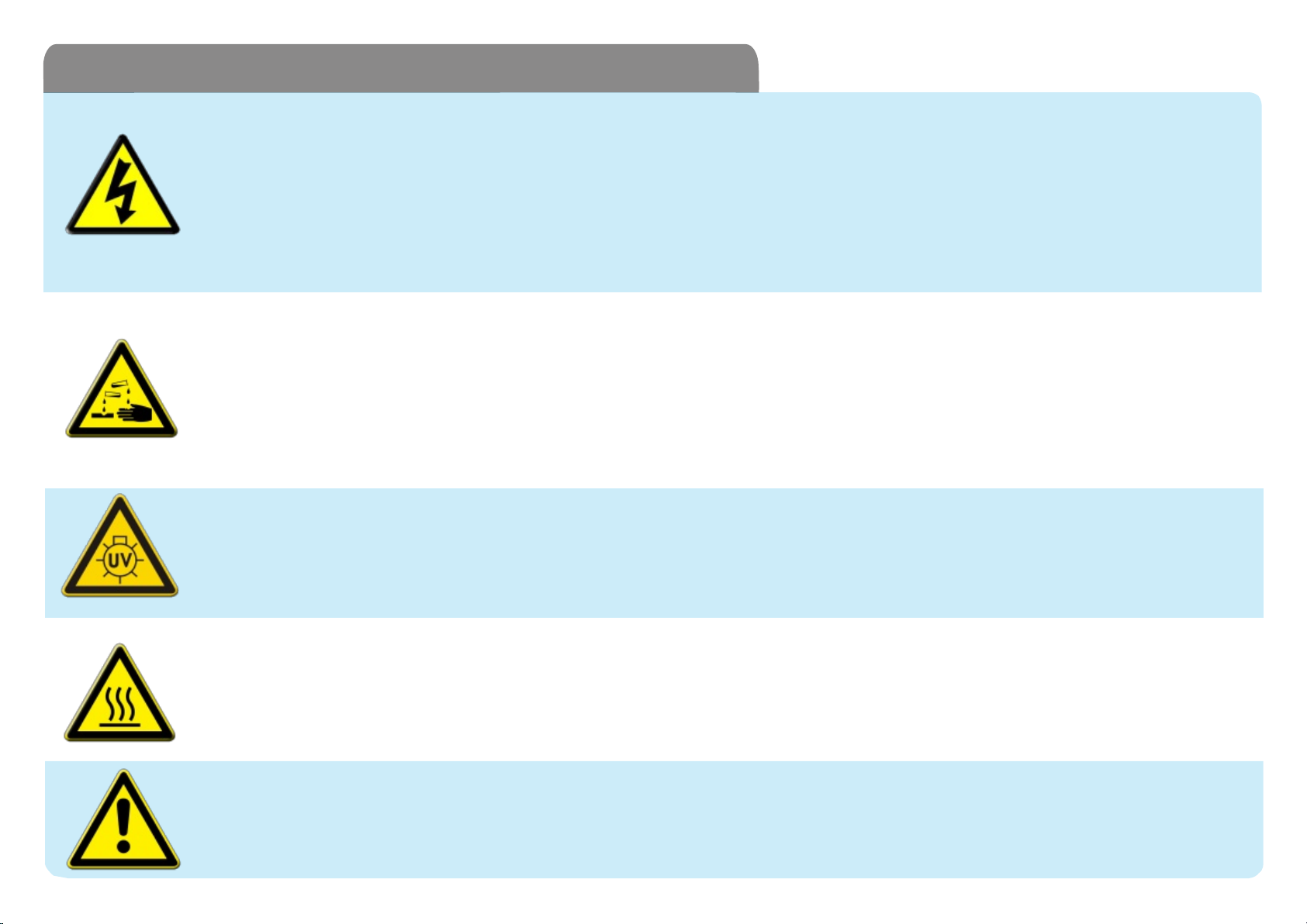
Tab. 1-1: List of hazards and dangers
Hazard of eletrical shock
This symbol is used to warn of a hazard of severe electric shock or electrocution. All controls and maintenance on electrical
devices labelled with this symbol should be made by qualified personnel in accordance with national or local regulations.
Qualified personnel means a person who has been fully trained and has professional experience to avoid electrical hazards
and dangers. To avoid potential fatal electrical shock and/or analyzer damage always disconnect input power to analyzer before
servicing.
Hazard of chemical burns
This symbol is used t o warn of a hazard of severe burns and seroius injury from dangerous chemicals. All handling and
manipulations during operation and maintenance of chemicals labelled with this symbol should be made by qualified personnel
in accordance with national or local regulations. Qualified personnel means a person who has been fully trained and has
professional experience to avoid chemical hazards and dangers. Before to proceed with the handling of chemicals or
operations read the material safety data sheets supplied with each chemical to ensure all the necessary precautions are taken.
Hazard of UV radiation
This symbol is used to warn of an hazard of ultraviolet radiation. It is obligatory to wear eye protection to operate with the UV
lamps labelled with this symbol.
Never look directly at a lighted UV lamp. UV radiation exposure can cause severe and permanent damage to skin and eyes.
Concerned parts:
Fans
Air compressors
UV power supplies
Main power supply
UV lamps
Pump motors
Input terminal
Corcerned parts:
Liquids enclosure
Reagents containers
Concerned parts:
UV lamps
Hazard of thermic shock and burns
This symbol is used to warn of an hazard of t hermic shock and burns. Some parts of the analyzer become extremely hot during
analyzer normal operations. Avoid skin contact with these surfaces and if necessary to service these parts be sure to
sufficiently enough to avoid burning. Always disconnect input power to analyzer before servicing these parts.
Warning of general hazard
This symbol means that is necessary read this manual before proceeding with any service operation to know exactly how to
operate in a proper way. Only qualified personnel or personnel fully trained on analyzer use and maintenance is allowed to
proceed with service operations on the unit.
Corcerned parts:
UV lamps
Pump motors
Air compressor
Concerned parts:
TOC analyzer
8
Page 9

7010 TOC ANALYZER - USER MANUAL
1.3 Vent waste gas
Waste gases coming from analyzer oxidation process depend on th e user’s sample composition. They are labelled on the external side of the
cabinet as VENT outlets. It is necessary to connect an extension tubing or to provi de for safe venting to the atmosphere or to a classified safe
area.
1.4 Sample
Take appropriate precautions to avoid direct contact with sample stream.
It is responsability of the user to be aware of and take all precautions
regarding physical, chemical, radiation and/or biological hazards and
dangers coming from sample stream and/or sample vapours. It is also
responsibility of the user to be aware of potential hazards regarding the
chemical and physical compat ibi lit y of sample stream with the analyzer
materials.
1.5 UV lamps disposal
Used or replaced UV lamps contain a small quantity of mercury and they
must be disposed according with national or local environmental
regulations regardin g hazardous and poisonus materials.
Table 1-2 : List of materials used in 7010 TOC Analyzer
Pump tubings
Fittings
Connection tu bings
GLS,U Tube,
Scrubber, Condenser
Halogens and sodalime filter body
Filter cont ent s
UV lamps
Bypass valve
IR cell
Gas dryer tubing
Norprene,Tygon
Polypropylene
PFA
Glass
PVC, p olycarbon at e
Copper wool (halogens filter),
Sodalime (CO2 filter)
Quartz
Noryl, viton
Stainless st eel
Nafion
9
Page 10
1.6 ANALYZER GENERAL HAZARDS
1.6.1 Electrical precautions and hazards
7010 TOC ANALYZER - USER MANUAL
In all electrical devices that are 230 VAC (or 115 VAC opt.) powered present hazards of
electrical shock or electrocution.
To protect all the personnel involved in analyzer use and maintenance, the doors of the two
analyser enclosures are equipped with a special key for opening.
If necessary to operate inside the electrical enclosure with the analyzer powered on, please
consider th at this operation must be made only by qualified personnel in accordance with
national or local regulations. Qualified personnel means a person who has been fully trained
and has professional experience to avoid electricity hazards and dangers.
Service qualif ied personnel will receive the special key to open the electrical enclosure.
Before to service the analyzer or parts of that electrically powered, turn off all power to avoid risk
of electrocut ion.
To turn off power from an electrical device is necessary to interrupt the power line using a circuit
breaker or an isolating switch to be sure that there is no power in the area being serviced.
Users and qualified maintenance personnels must proceed as follows:
pay attent ion to electrical shock and/or electrocutions labels placed on the analyser
always isolate power before servicing the analyser
In case of loss of power the analyser stops and will automaticall y restart as soon as power is
restored.
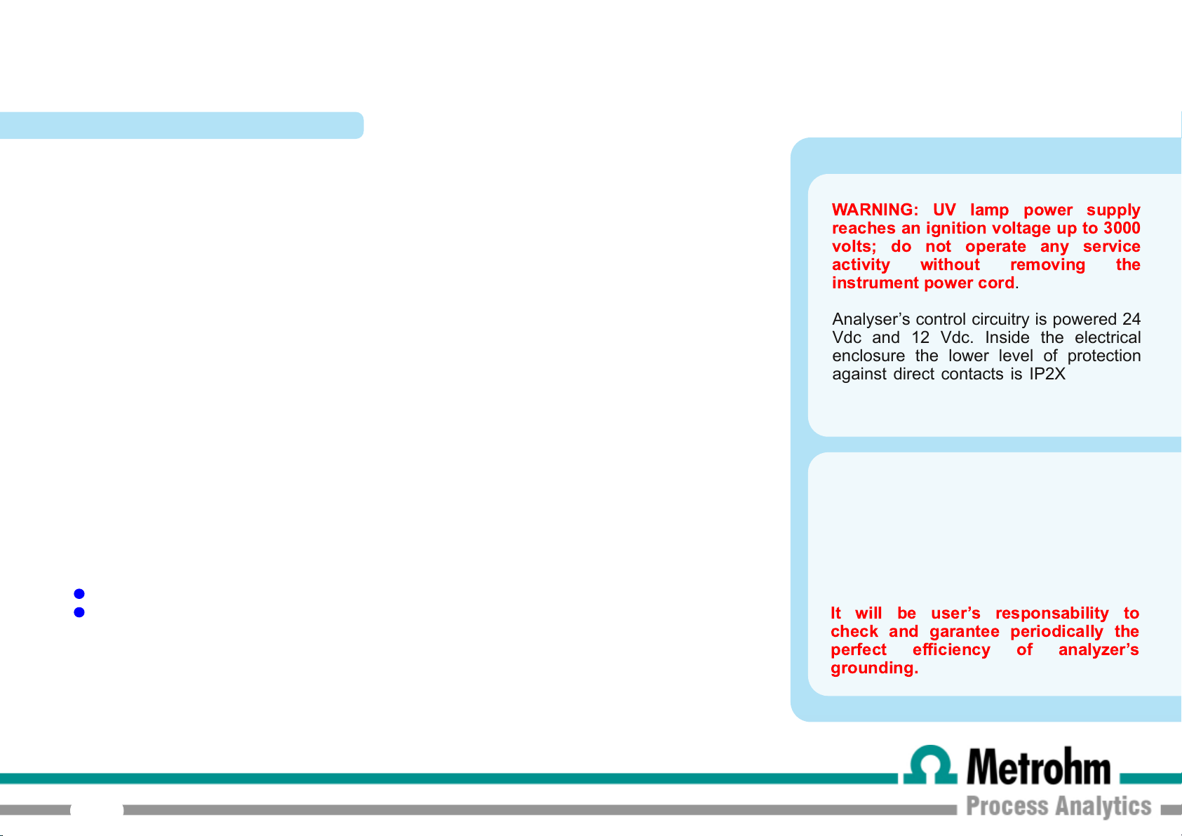
WARNING: UV lamp power supply
reaches an ignition voltage up to 3000
volts; do not operate any service
activity without removing the
instrument power cord
Analyser’s control circuitry is powered 24
Vdc and 12 Vdc. Inside the electrical
enclosure the lower level of protection
against direct contacts is IP2X. Analyzer
enclosures are IP54 (because of air fans
holes).
Protection against indirect contacts is
guaranteed by efficient grounding of all
isolated metal masses.
Grounding bar is located inside the
electrical enclosure, in upper left position
below the protection cover.
It will be user’s responsability to
check and garantee periodically the
perfect efficiency of analyzer’s
grounding.
.
10
Page 11
1.6.2 Operating precautions and hazards
7010 TOC ANALYZER - USER MANUAL
HAZARD:
PREVENTIVE ACTIONS:
HAZARD:
PREVENTIVE ACTIONS:
HAZARD:
PREVENTIVE ACTIONS:
Mechanical hazards caused by moving parts such as fans, pumps, motors and air compressors
To avoid risks the analyzer’s moving parts have been designed, built and located in a closed enclosure with a
special opening key. Where present inside the enclosures, these parts have protection covers to avoid any contact
and physical injury to users.
Hazards of burns caused by hot parts of UV lamps, motors and air compressors
To avoid risks, the analyser’s parts that become very hot to the touch have been designed, built and located in
closed enclosure with a special opening key. When present inside the enclosures, these parts have protection
covers and warning labels to avoid any contact and physical injury to users.
Hazard of poisoning caused by waste gas coming out from VENT line
Install t he analyser in location of adequate dimensions and well ventilated.
HAZARD:
PREVENTIVE ACTIONS:
11
Hazards of UV radiation exposure caused by UV lamps
To avoid risks, the analyser’s parts that produce UV radiation emissions have been designed, built and located in
closed enclosure with a special opening key. When present inside the enclosures, these parts have protection
covers and warning labels to avoid any contact and/or exposure and/or physical injury to users.
Page 12
7010 TOC ANALYZER - USER MANUAL
HAZARD:
PREVENTIVE ACTIONS:
HAZARD:
PREVENTIVE ACTIONS:
Hazard of electric shock and/or electrocution in the
electrical enclosure
The analyser’s electric equipment complies with
EN 60204
To avoid risks, the analyser’s parts that can cause
hazard of electric shock and/or electrocution have
been designed, built and located in a closed
enclosure with a special opening key. When
present inside the enclosures, these parts have
protection covers and warning labels to avoid any
contact and serious injury or death to users.
Hazard of burns and poisoning caused by contact with dangerous chemicals
To avoid risks, the analyser ’s parts that can cause contact wit h chemicals have been designed, built and locat ed in
closed enclosure with a special opening key. Before to service the liquids enclosure, read the material safety data
sheets supplied with each chemical to t ake all the necessary precautions when handling. Wear eye protections,
gloves, mask and protective clothing if necessary.
requirements.
Electrical equipments of input power and grounding must
comply the national or local regulations and laws.
Check that the source voltage to be used corresponds
with that requested by the analyser.
Check periodically the power cord as well as the analyser
grounding.
WARNING:
voltage up to 3000 Volts; do not undertake any service
activity without removing the instrument power cord.
NOTE :
UV lamp power supply reaches an ignition
1.6.3 Chemical and waste gas hazards
The analyser has been designed, built and equipped to avoid risks caused by physical and chemical factors as noise, vibrations, radiations, dust,
waste gas etc.
12
Page 13
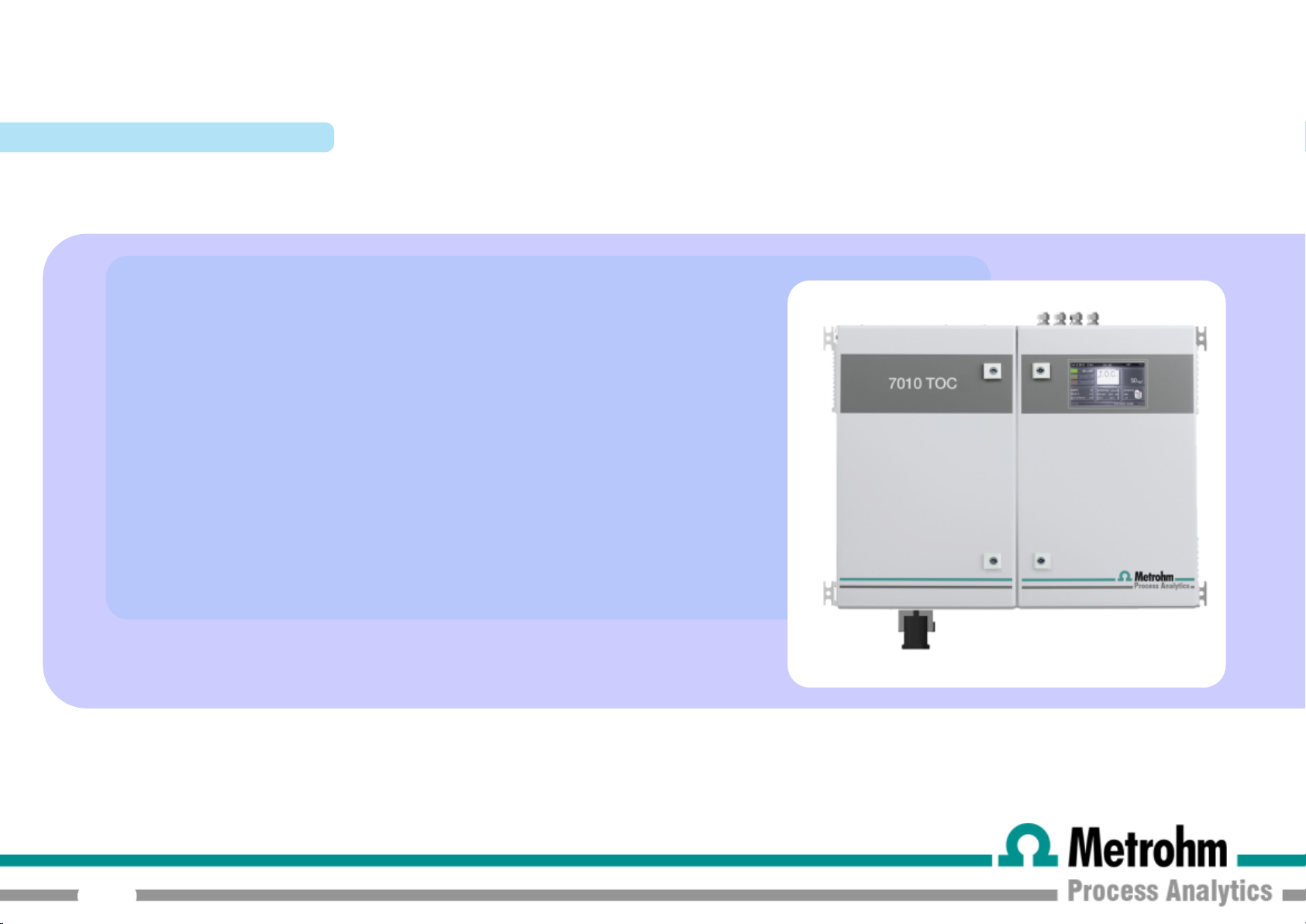
2.0 ANALYZER DESCRIPTION
This manual provides general information regarding the principle of
operation and proper installation and operation of the 7010 TOC A nal yser .
The analyser measures Total Organic Carbon in liquid samples using the
EPA approved method based on UV persulfate oxidation and detection of
generated carbon dioxide using a Non Dispersive Infrared analyser. This
method meets also the requirements of European ISO/CEN guidelines. The
analyser provides this measurements on liquid samples ranging from 0-5
7010 TOC ANALYZER - USER MANUAL
mg/l to 0-20000 mg/l.
The analyser conforms to EPA, DIN, CE, AST M and NAMUR regulations.
13
Page 14

2.1 APPLICATIONS
The
701 0 TOC
(TOC) in water.
It has been designed for the following applications:
Industrial wast e water
Condensate and cooling water
Drinking and river water
analyser continuously measures Total Organic Carbon
7010 TOC ANALYZER - USER MANUAL
Industrial wat er treatment plant inlet/outlet
For different applications or different aqueous matrices it is recommended
to contact your Metrohm distributor to verify your application with our
specialists.
14
Page 15

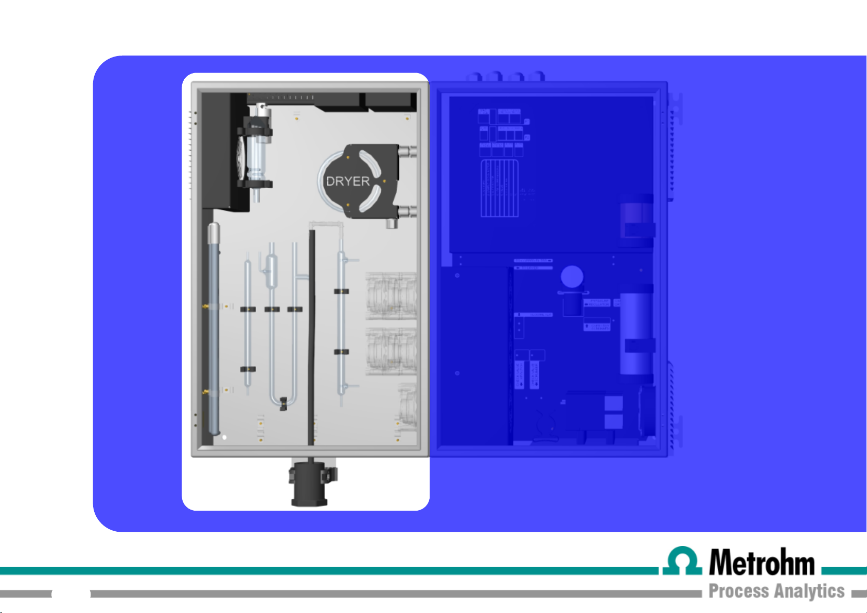
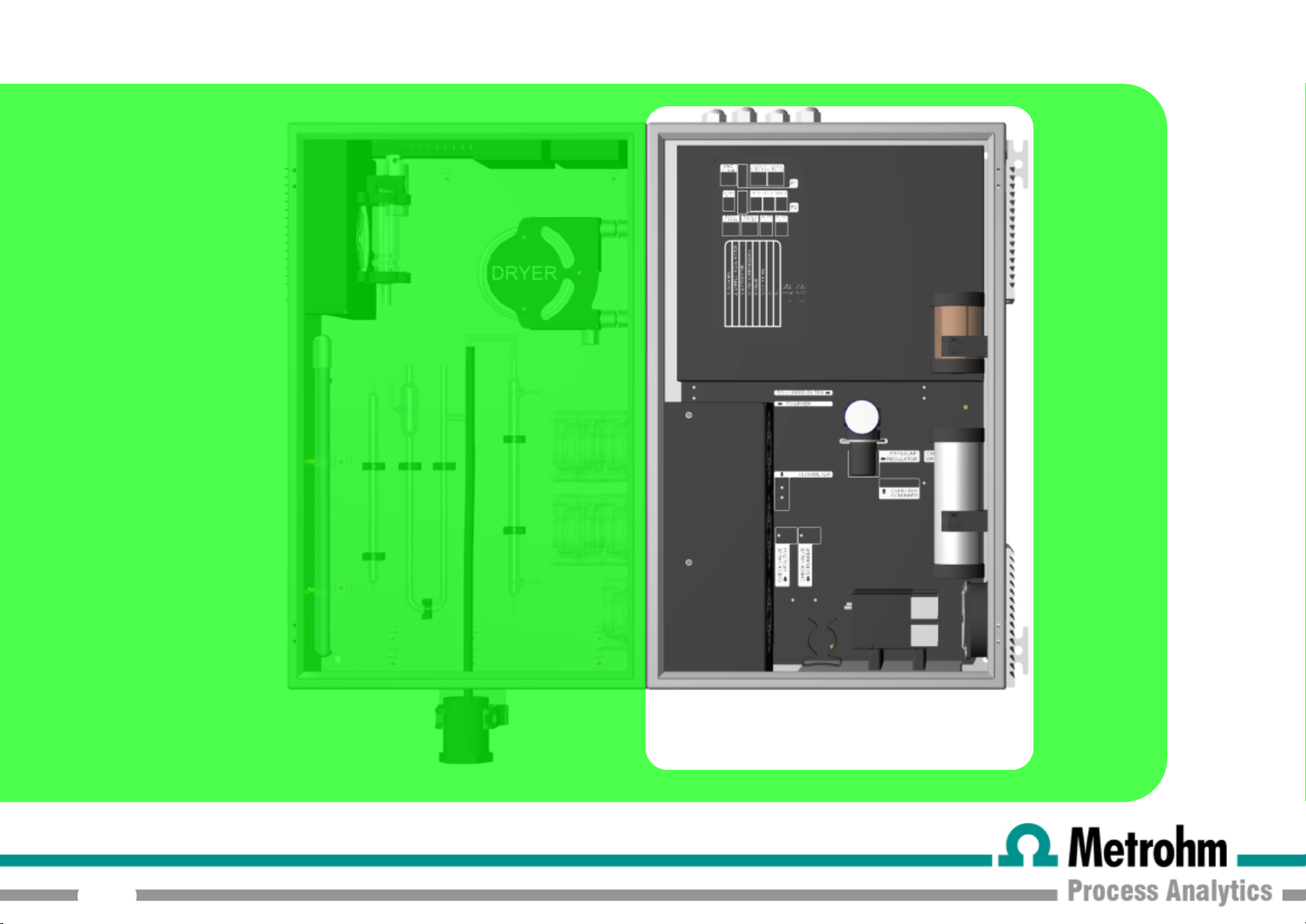
7010 TOC ANALYZER - USER MANUAL
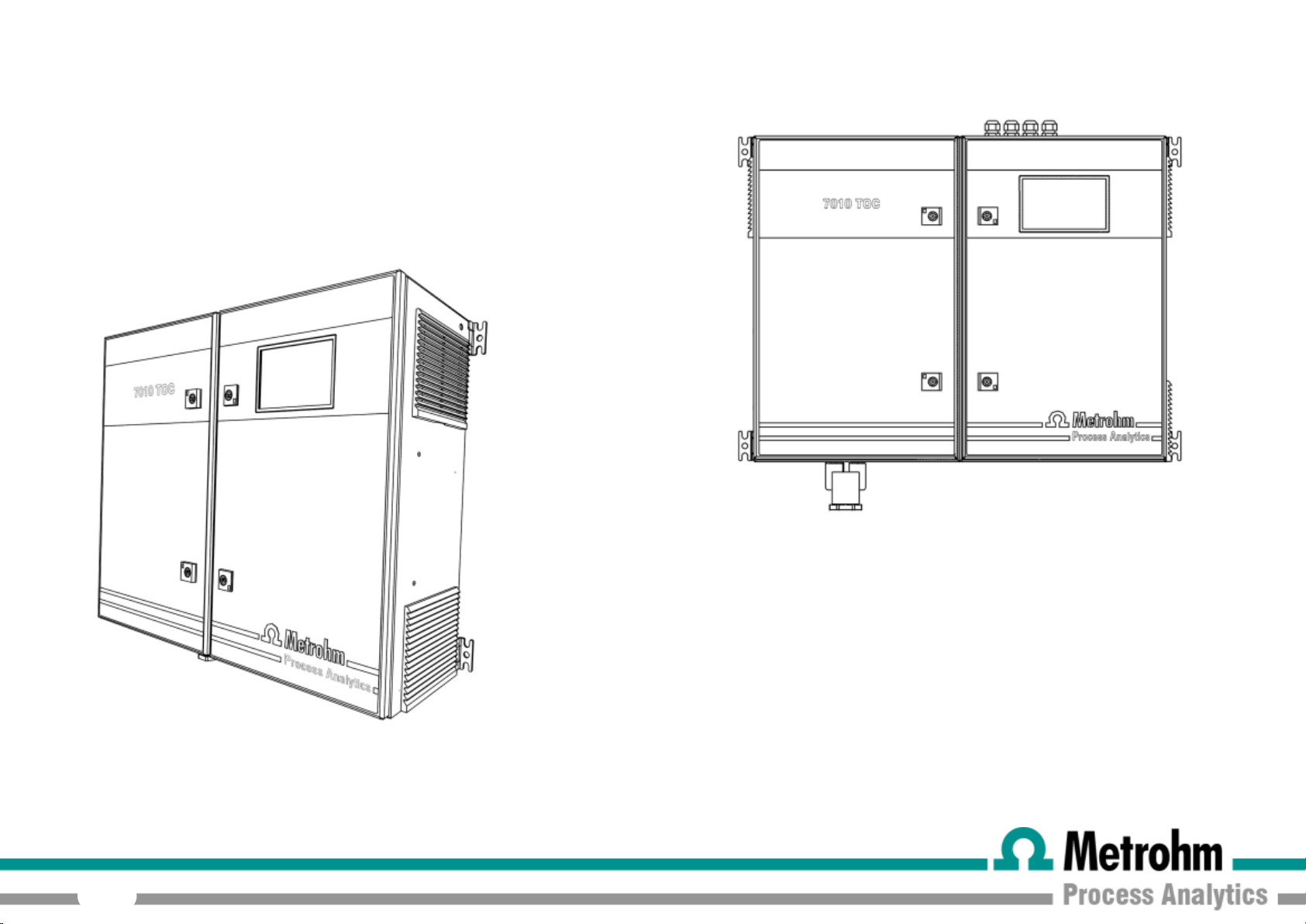
The analyser is assembled in two separated enclosures. The first one, called
LIQUIDS enclosure
, includes all the components involved in sample and reagent flows as well as
their mixing in sparging and oxidation stages. This enclosure is properly vented by a fan to allow good air refreshment inside the cabinet. The second one, called
enclosure
, includes the main power supply, the carrier gas generation and flow adjustment devices, the controlleing PCB assembly and the infrared detector.
legend:
01)
UV lamp power supplies
02) glass condenser
03) by-pass valve
04) condenser fan
05) dryer tubing
06) UV reactor
07) resample pump
08) sample pump
09) persulfate pump
10)
phosphoric acid pump
11) auto pump
12) UV scrubber
13) U-tube
14) scrubber
15) drain
ELECTRICAL
legend:
01) user connections
02) copper filter
03) pumps motor
04) pressure regulator +
flow capillary
05) sodalime filter
06) dryer + scrubber
capillary
07) flowmeter
08) check valve
09)
carrier gas compressor
10) scrubber gas
compressor
11) fan
12) air filter
13) NDIR
15
Page 16
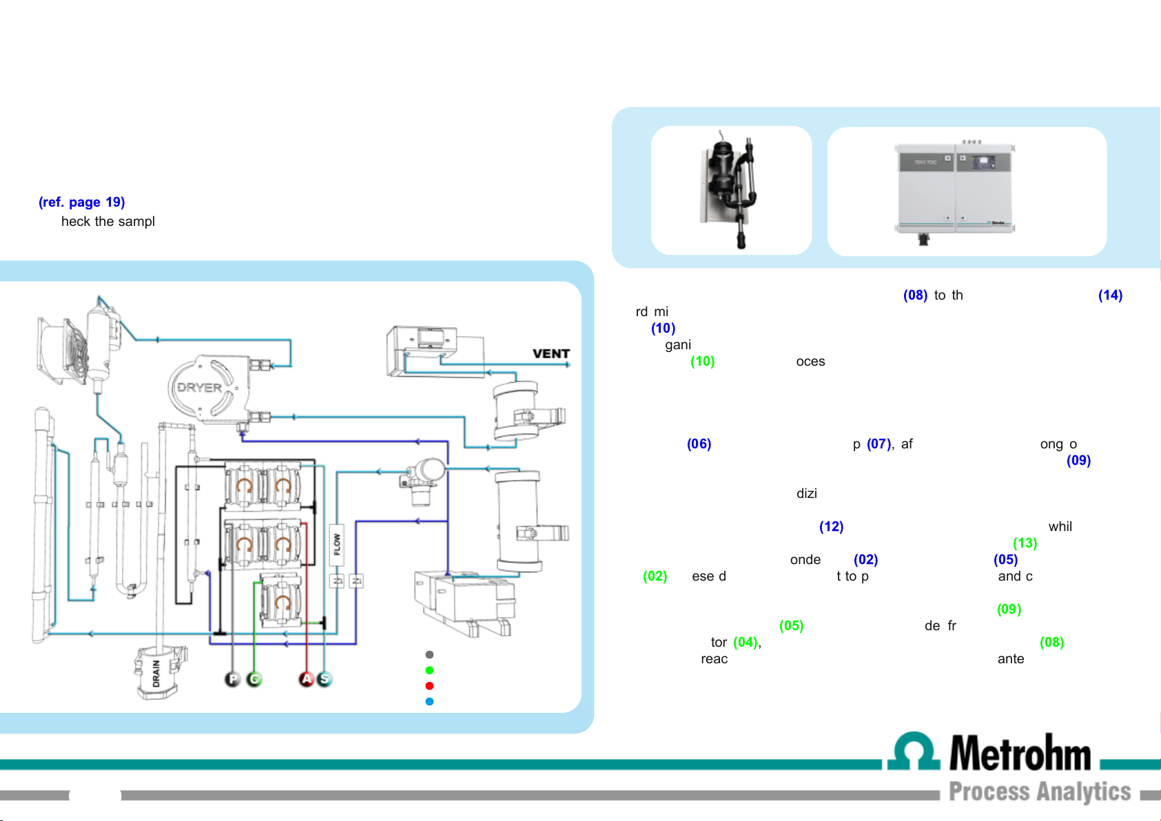
2.2 OPERATING PRINCIPLE
SODIUM PERSULFATE
CLEANING
ACID
SAMPLE
The water from the sample source (directly from the sampling point or through the optional
filtration unit) is fed to a sampling device mounted on the external left side of the analyzer
(ref. page 1 9)
to check the sample presence. This device allows a good sample refreshment and will put
the analyzer in stand-by condition in case of loss of sample.
. This device drains the sample excess and is equipped with a level sensor
7010 TOC ANALYZER - USER MANUAL
The sample is pumped by a peristaltic pump
afterd mixing with acid (usually phosphoric acid) pumped by a second peristaltic
pump
(1 0)
.
The inorganic removal is performed using ambient air provided by an internal air
compressor
carbon carbonates to carbon dioxide. The carbon dioxide dissolved in water is then
driven out by the sample to the vent using compressed air.
The acidified and sparged sample is then pumped from the scrubber bottom to the
UV reactor
agent (usually sodium persulfate) pumped by a dedicated peristaltic pump
The presence of a strong oxidizing agent combined with high level UV radiation
causes the oxidation of organic compounds. The produced carbon dioxide is
driven to the gas-liquid separator
that containing carbon dioxide goes to the infrared analyser
sequence through a glass condenser
filter
(02)
the stainless cell of the IR. The carrier gas used for the oxidation and detection
stages is generated by a second internal a ir compressor
through a sodalime filter
pressure regulat or
finally the UV reactor. All these devices are necessary to guarantee high precision
and stability of carrier gas flow as well as to control and be able to display the flow.
(1 0)
. This first process lowers the pH of the sample and convert the
(06)
by the resample pump
(1 2)
. The liquid sample is drained off while the air
(02)
. These devices are present to prevent condensation and corrosion inside
(05)
. The carbon dioxide free gas passes through a
(04)
, a capillary tubing and a digital flowmeter
(08)
to the inorganic scrubber
(07)
, after mixing with a strong oxidizing
(1 3)
, passing in
, gas drier tubing
(05)
and a halogens
(09)
and is passed
(08)
(1 4)
(09)
.
to reach
16
Page 17
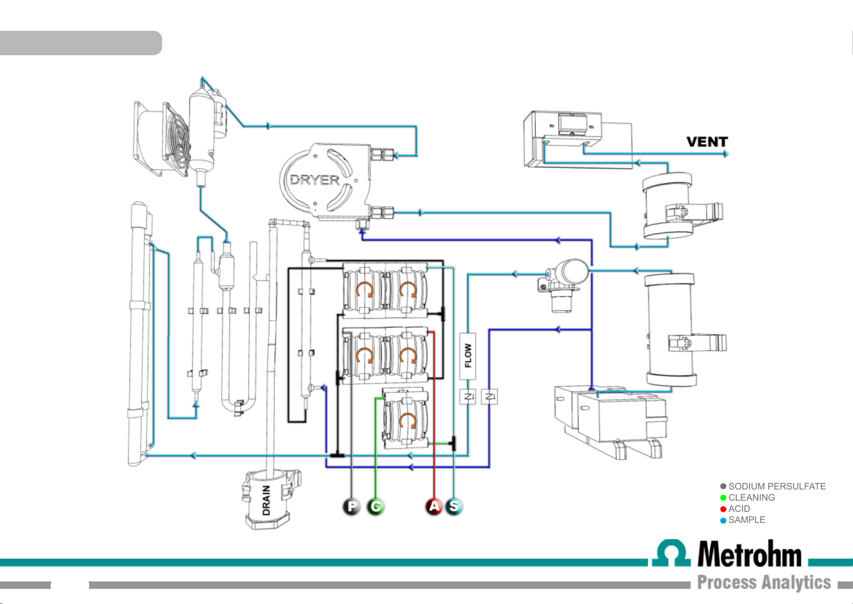
SODIUM PERSULFATE
CLEANING
ACID
SAMPLE
TOC FLOW DIAGRAM
7010 TOC ANALYZER - USER MANUAL
17
Page 18
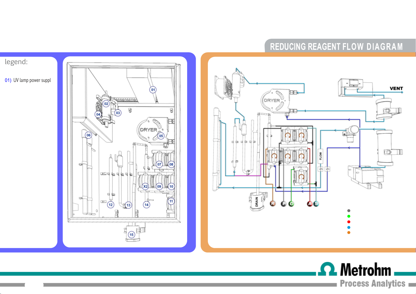
legend:
01)
UV lamp power supplies
02) glass condenser
03)by-pass valve
04) condenser fan
05) dryer tubing
06) UV reactor
07) resample pump
08) sample pump
7010 TOC ANALYZER - USER MANUAL
REDUCING REAGENT FLOW D I AGRAM
09) persulfate pump
10)
phosphoric acid pump
11) auto pump
12) UV scrubber
13) U-tube
14) scrubber
15) drain
X2)
reducing reagent pump
18
SODIUM PERSULFATE
CLEANING
ACID
SAMPLE
REDUCING REAGENT
Page 19
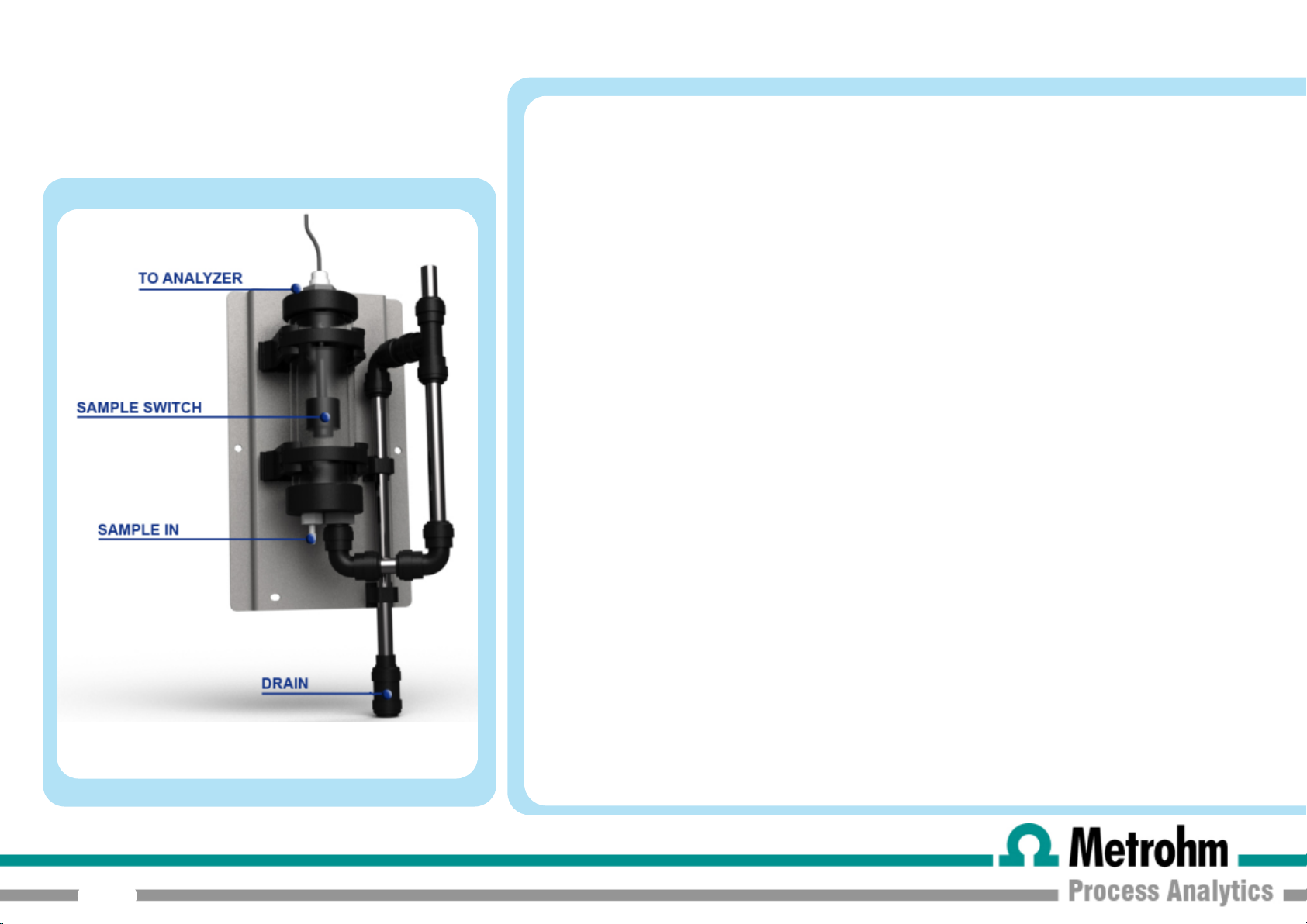
2.3 FAST LOOP RESERVOIR
7010 TOC ANALYZER - USER MANUAL
The external reservoir allows a fast circulation of the sample coming f rom the sampling point or from the
optional filtration unit.
Inside the fast-loop reservoir the sample is at atmospheric pressure and this allows the sample pump to
function with a constant delivery and no overpressure.In addition, the fast-loop reservoir is a usef ul extra
quantity of sample to avoid wrong alarms in case of a short loss of sample as well as eliminating air
bubbles coming from the sample line or from t he cleaning cycle of the optional filtration unit.
The stainless steel drain tubing keeps a constant water level inside the container and allows a proper
sample circulation to avoid suspended solids accumulation.
The sample flow should be adjusted to have a constant sample overflow through the stainless steel tube.
Up to 3 level switches can be connected to the analyzer, e.g. Stream A,Stream B and dilution water. Two
of the switches are normally connected to the terminals that are foun d at the left hand side of the
analyzer. For a dual stream analyzer where dilution water is also required for one or both streams, the
third level switch is connected to the user connection inside the analyzer (see page 37).
19
For a single stream analyzer, in the even t of a missing sample or dilution water stream for a period longer
than a preset time (normally set on installation to 30 s), an ala rm - LOSS OF SAMPLE - is triggered and
the analyzer switches to Standby. When the missing sample or dilution water stream is reestablished, the
analyzer restartsautomatically with a conditioning cycle.
In the case of a dual stream configuration, if no Stream A is present then the analyzer will continue to
work only on Stream B until Stream A is reestablished, and vice-versa. If both streams are not present
then again the alarm LOSS OF SAMPLE is triggered and the analyzer switches to Standby.
If either or both streams are being diluted and the dilution water stream is missing, then jumpers found
alongside the internal Level 3 terminal can be used to make the analyzer work only on the undiluted
stream or switch to Standby if both streams are diluted, again giving the alarm LOSS OF SAMPLE.
Page 20
7010 TOC ANALYZER - USER MANUAL
20
LIQUID ENCLOSURE
Page 21
7010 TOC ANALYZER - USER MANUAL
2.4.1 PERISTALTIC PUMPS
In normal on-line conditions t he 7010 TOC analyser uses two pump motors with two pump heads driven by each motor.
An extra pump head driven by a specific motor is used just in autocalibration, autovalidation or autocleaning cycles.
The sample pump head shown in flow diagram as
closest to the motor. It pumps the sample from the external reservoir to the T fitting connected on the other side to
the phosphoric acid pump head. Optimizing the sample pump flowrate is important to have a representative sample and
to reduce the analyser response time.
The phosphoric acid pump head
It pumps phosphoric acid from the phosphoric acid container to the T fitting connected to sample pump head
acid addition to the sample is necessary to lower the sample pH and to remove the inorganic carbon (IC) by gas
sparging.
The resample pump head
the acidified and sparged sample from the bottom of the scrubber
gas coming from the air compressor
The persulfate pump head
sodium persulfate from the persulfate container to the UV reactor
coming from the resample pump
(1 0)
is driven by the M2 motor and is located in the middle position,closest to the motor.
(07)
is driven by the M1 motor and is located in the upper position, UV lamps side. It pumps
(09)
and directed to UV reactor
(09)
is driver by the M2 motor and is located in the middle position, UV lamps side. It pumps
(07)
and after is directed to UV reactor
(08)
is driven by the M1 motor and is located in the upper position,
(1 4)
to the T connection where it mixes with the carrier
(06)
.
(06)
, adding it to the mixture of sample and carrier gas
(06)
.
(08)
(1 0)
. The
21
The auto pump head shown in flow diagram as
standard solution or the cleaning solution from its container to the analysis circuit when requested by the user or when
programmed as autocal/val/clean cycle. The auto pump flowrate is higher than sample pump flowrate. This means that in
case of an autocleaning cycle a portion of the cleaning solution will be driven towards the sample inlet, cleaning the
sampling point.
(11 )
is driven by the M3 motor. It pumps the calibration/validation
Page 22
2.4.2 SCRUBBER
7010 TOC ANALYZER - USER MANUAL
The scrubber
It is a glass cylinder with the acidified sample inlet in upper right position. The acidified sample passes down by gravity
through the scrubber and it’s sparged by the carrier gas coming from air compressor
position.
The carbon dioxide coming from the inorganic carbon present in the sample is sparged by the carrier gas flow and
removed from the sample through the vent/drain tubing connected to the straight upper position of the scrubber.
As a result, the sample at the scrubber bottom is IC free and it can be pumped by resample pump
stage.
2.4.3 UV REACTOR + UV SCRUBBER
The UV reactor
The reaction of oxidation is catalyzed by UV radiat ion with decomposition of sodium persulfate and creation of
strongly oxidizing radicals. These conditions ensure the best recovery of organics present in the sample.
The second UV lamp is connected to UV scrubber
inside this device.
(1 2)
is located in a vertical position near the peristaltic pumps.
(06)
is located on the left side of liquids enclosure. It consists of two high energy UV lamps.
(1 2)
. The oxidized sample at the UV lamps is sparged
(1 0)
, connected in the lower right
(07)
to the oxidation
22
Page 23
2.4.4 U-TUBE
7010 TOC ANALYZER - USER MANUAL
2.4.5 GLASS CONDENSER
The U-Tube
inlet and two outlet points.
It separates the analyzed liquid part of the sample coming from UV reactor from the gaseous stream direct ed
to the infrared analyser. It also drains the exausted sample and vents the sparging gas coming from the top of
the scrubber.
The gas mixture coming from the oxidation stage is driven by the carrier gas to the drying devices through the
upper right outlet of the gas-liquid separator, towards to the glass condenser
The Glass condenser
temperature difference between its glass body, cooled by a fan, and the hot treated sample coming from UV
reactor.
(1 3)
is located in the middle position of liquids enclosure. It is a U shaped glass device, with two
(02)
.
(02)
is positioned between U tube and the by-pass valve. The glass condenser uses the
23
Page 24
2.4.6 DRYER
7010 TOC ANALYZER - USER MANUAL
2.4.7 BY-PASS VALVE
The dryer
concentric tubes. In the internal tubing flows the gas stream to dry. This tubing is water vapour permeable so
that the humidity passes to the external tubing. In the external tubing there is a counter-current purge gas flow
that removes the water vapour. The dryer prevents water condensation inside the IR cell
CAUTION : do not overtighten or twist gas dryer ends when installing or servicing, as this will restrict
the airflow.
The By-pass valve shown in the diagram as
It vents the gas stream avoiding it to flow through the IR cell when not strictly necessary.
(05)
is positioned between the BY-PASS VALVE and the IR detector. It consists of a coil of two
(03)
is activated during conditioning and cleaning phases.
24
Page 25
7010 TOC ANALYZER - USER MANUAL
25
ELECTRICAL ENCLOSURE
Page 26

2.5.1 COPPER FILTER
7010 TOC ANALYZER - USER MANUAL
2.5.2 SODALIME FILTER
The copper filter
plastic container filled with copper wool. The gas leaving the dryer tubing is forced to go through this device to
prevent corrosive effects due to gases like chlorine or chlorine dioxide that could be generated in the oxidation
stage.
The sodalime filter
and it absorbs the carbon dioxide from atmospheric air providing the analyzer with CO2 free air for its
processes.
(02)
is located in the electrical enclosure immediately before the IR detector inlet. It is a
(05)
is located on the left side of electrical enclosure. It’s a plastic container full of sodalime
26
Page 27

M1
M2
M3
2.5.3 PUMP MOTOR
7010 TOC ANALYZER - USER MANUAL
The pump motors
M1,M2
and
M3
are positioned in the
electrical enclosure, on the left side.
They drive multiple pump heads that move the sample and
reagents throug h the different analyser t reat ment stages.
Depending on the configurations there will be from three to six
pump heads.
Motor rev/min Position Driven pumps
M1 05-06 rpm upper sample
M2 1 rpm middle acid
Pump Head mL/rotation
14 0,21
16 0,8
15 1,7
24 2,8
resample
persulfate
27
optional reducing reagent
M3 10-12 rpm lower calibration
validation
cleaning
Page 28

2.5.4 AIR COMPRESSORS
7010 TOC ANALYZER - USER MANUAL
2.5.5 PRESSURE REGULATOR
CAPILLARY AND FLOWMETER
The air compressors
provides the sparging gas used in the scrubber and the counterflow gas in the dryer.The second compressor
(09)
provides the carrier gas for oxidation and detection stages. They eliminate the need for an external air
treatment system and for compressed air as a requested utility, this saving cost.
These devices
the front and are used to they allow for a highly precise and reliable adjustment for the carrier gas flow.
(04)
(09)
and
and
(1 0)
are located on the lower side of the electrical enclosure. Compressor
(07)
are located in the central part of the electrical enclosure with a pressure gauge on
(1 0)
28
Page 29

2.5.6 NDIR
7010 TOC ANALYZER - USER MANUAL
2.5.7 USER CONNECTIONS
The infrared analyser
board fitted with a stainless steel cylinder (the IR cell). It’s a Non-Dispensive Infrared analyser (NDIR) with high
stability and reliability. The measuring scale of IR is related to the range of
701 0 TOC
analyzer provides:
1 4-20 mA output (A01). (A second 4-20 mA output (A02) is available on dual channels analyzers).
2 relays (RELAY A - programmable and RELAY B - fault)
1 24 Vdc
1 digital input
(1 3)
is located in the higher part of the electrical enclosure, on the right side. It is a PCB
701 0 TOC
29
1 digital output
1 level 3 - additional contact
RS485
Page 30

7010 TOC ANALYZER - USER MANUAL
30
INSTALLATION
Page 31

3.0 UNPACKING AND INSPECTING
The
701 0 TOC
performances di rect ly in our facilities and it’s delivered inside a wooden
box. Before to proceed with analyser installation, it is recommended to
check carefully that box and analyzer have not been damaged during
transportation. Take extreme care during analyzer unpacking and
moving.
analyzer is assembled and fully tested for proper
3.1 ANALYZER MOVING
Take extreme care when lifting or moving the analyzer, its weight is about
37 kg. Before t o move the analyzer it is recommended to empty
manually the glass p art s of liquids enclosure using an appropriate plastic
syringe and tubing.
7010 TOC ANALYZER - USER MANUAL
3.2 LOCATION AND MOUNTING INSTRUCTION
It is recommended to install the analyzer in a suitable position. The
location must be clean, covered and properly enclosed to provide the
analyser with good ventilation and low dust concentration. Operating
environmental conditions are: temperature between 5 and 40° C at max
80% relative humidity.
Due of chemicals and waste gases it is absolutely necessary to choose a
well ventilat ed location for the analyzer.
31
The
701 0 TOC
wall or stainless steel support rack installation. Use 4 screws M8 to
fix the analyzer.
The analyser should be mounted with the display at eye level for
easier operation and access.
analyzer is supplied with four mounting brackets for
Page 32

3.3 PRECOMMISSIONING
Liated below are key points that must be followed in order to have
an ideal installation:
the installation site should be as near to the sampling point
as possible to reduce delay in response time
the drain line should be properly dimensioned and positioned
with downward slope to allow the draining of analysed
sample and the overflow coming from the external fast-loop
reservoir. ( If the optional filtration unit is present, the drain
pipe should be dimensioned to drain also the sample coming
out from filtration system fast-loop).
Clearance requirements for the analyzer should be 20 cm on
either side and 100 cm on the front
7010 TOC ANALYZER - USER MANUAL
Sufficient space for two 10 liter containers and one 5 liter
container should be provided beneath the ana lyzer; if
necessary, the reagents containers should be positioned in
a suitable receptacle in case of spills
Dedicated waste gas line should be provided for safe venting
to the atmosphere unless installed in a well ventiled area of
adequate dimensions.
ATTENTION: depending on the sample chemical composition,
its oxidation can generate hazardous gases. In these cases it’s
strictly necessary to provide a safety system to allow waste
gases vent to the atmosphere
32
WARNING: the sample drain of the analyzer must be at
ambient pressure with no restriction or counterpressure.
Please verify that this condition has been strictly respected
during installation.
Page 33

3.4 ELECTRICAL CONNECTIONS
All electrical connections should be made by qualified personnel in accordance
with nationa l or local codes and regulations.
Qualified Personnel means a person who has been fully trained and has
professional experien ce to avoid electrical hazards and dangers.
Service qualified personnel will receive the special key to open the electrical
enclosure.
A circuit breaker must be installed near the analyzer to allow easy isolation of
power in case of electrical problems and every time it is necessary to service the
analyzer.
7010 TOC ANALYZER - USER MANUAL
It will be user’s task to check and guarantee periodically the perfect functionality
of the analyzer’s grounding.
To avoid potential fatal electrical shock and/or analyzer
damage always disconnect input power to analyzer before
servicing (disconnecting the 115 VAC - 230 VAC plug)
ALWAYS ISOLATE POWER BEFORE SERVICING
33
Page 34

3.4.1 AC POWER CONNECTION
The
701 0 TOC
Hz power. I t is provided with 2 meter long power cord and European
Schuko plug (ref. CEE 7/ VII re gulat ion). Optional configuration with 115
Vac power supply and US plug. The analyzer is delivered with the power
cord wires are already connected to terminals AC section of
CONNECTIONS
AC power enters on the top side of the electrical compartments through
the supplied power cord.
All the connections must be made in accordance with national or local
regulations. It is recommended that the analyzer has its own dedicated
circuit with a circuit breaker or an isolating switch installed near the unit.
analyser is designed fo r operation with 230VAC, 50/60
USER
.
7010 TOC ANALYZER - USER MANUAL
3.4.2 ANALOG OUTPUT CONNECTIONS
The
701 0 TOC
outputs for analysis value. Wiring connections use a twisted-pair signal
cable with shield connected to the A/01 or A/02 located right on top of
electrical enclosure.
34
analyzer provides 2 optically isolated 4-20 mA analog
Page 35

3.4.3 RELAY A/B
NO ALARM: C NC / ACTIVE ALARM: C NO
RELAY A function is programmable in the general setup page.
Here below the list of the possible functions:
online (relay activated when analyzer is online)
offline (relay activated when analyzer is offline)
loss of sample (relay activated in case of loss of sample alarm)
result alarm (re lay activated in case of result higher than the
programmed value)
validation alarm (relay activated in case of validation alarm)
reagent alarm (relay activated in case of reagent's alarm)
calibration alarm (relay activated in case of calibration alarm)
7010 TOC ANALYZER - USER MANUAL
RELAY B is activated in case of fault alarm
Fault alarms occur if certain conditions arise that risk the analyzer giving
incorrect results. T hey are as follows:
carrier gas flow too low
reagent levels too low
zero gas too high
emergency stop activated
35
Page 36

3.4.4 RS 485
MODBUS RTU CONNECTION GUIDE 7010 Toc
Baud Rate 9600
Data bits 8
Parity E
Stop bit 1
Slave I.D. 1
Address format alias
150 32-bits float (CD-AB) result CH1
152 32-bits float (CD-AB) result CH2
154 16-bit unsigned analyser status
7010 TOC ANALYZER - USER MANUAL
RS 485 SETTINGS
PROTOCOL
VALUES
STATUS VALUES
Stand by 0
Conditioning (to drain) 3
Conditioning (purge detector) 4
Online 5
Zerogas 6
Zerogas 7
Auto Function 1
Stopped 8
36
Page 37

3.4.5 DIGITAL INPUT/EXTRA RELAY
Digital input is a remote function available for the following features:
Start / Stop
Digital input ' s function is selectable by the user.
Extra Relay is used for external operations. (24V DC available) for
powering external devices. This output may be configured for separate
ON and pause periods. The ON period is configurable between 1 and 99
seconds, the pause period is configurable between 1 and 999 minutes.
3.4.6 LEVELS
Level switch terminals - level 1 and level 2 works with same logic as
level switches left side connectors. Additional level 3 can be configured
with jumpers in order to be associated to 1, 2 or 1 & 2.
C is the common terminal.
7010 TOC ANALYZER - USER MANUAL
3.4.7 EXTERNAL DILUTOR SUPPLY
230/115 Vac for supplying power to the external dilutor. Functions when
the analyzer is in Conditioning and On-line mode.
3.4.8 FUSES
The analyzer has 2 fuses.
Fuse F1 power supply fuse 3.15 A for 230 V version
4 A for the 115 V version
Fuse F2 IR detector/digital flowmeter 1.25 A
37
Page 38

Before to proceed with analyzer start-up it is absolutely necessary to check that all the operations for a proper
installation and reagents preparation have been properly carried out.
Please verify that all the suggestions and recommendations has been respected.
After t his double check, please proceed as follows:
Connect the sample line inlet tubing (or filtered sample outlet coming from optional filtration system) to the fast-loop reservoir installed on
the left side of the 7010 TOC analyzer
Connect the drain fitting of the fast-loop reservoir to the waste line
Put the acid inlet tubing (red label) in the phosphoric acid container beneath the analyzer and check that it is correct by position at the
bottom of the container
7010 TOC ANALYZER - USER MANUAL
Put the persulfate inlet tubing (white label) in the sodium persulfate container beneath the analyzer and checkthat it is correct by position
at the bottom of the container
Put the cleaning (or calibration or validation) solution inlet tubing (green label) in the cleaning (or calibration or validation) solution
container placed beneath the analyzer and check that it is correct by position at the bottom of the container
Connect the funnel beneath the analyzer is connected to the waste DRAIN line
Check sample presence in fast-loop reservoir and adjust the sample flowrate (suggested 100-500 ml / min)
Switch on power to the analyzer. External fans, microprocessor and infrared analyzer will start.
38
Page 39

The analyzer will proceed as follows:
7010 TOC ANALYZER - USER MANUAL
if the analyzer has been previously shut off in
operation but measurement and output signal are not still valid until the conditioni ng delay has expired.
if the analyzer has been previously shut off in
press
operation but measurement and output signal are not still valid until the conditi oning delay has expired.
In the next few following minutes it is necessary to check:
sample presence in the scrubber, sample presence in the gas-liquid separator.
free draining waste with no restriction of gas-liquid separator drain outlet. The drain tube must not be submerged and the exhausted sample
must be carried out by gravity.
It is not recommended to proceed with a
IMPORTANT NOTE:
During analyzer’s initial start-up it is necessary to decide to confirm cleaning as the automatic option (programmed as default option)
or change to validation or calibration.
ONLINE
button on the display. This forces t he analyzer to start immediately with a conditioning cycle. The analyzer is totally in
zerogas cycle
ONLINE
STANDBY
and a
calibration cycle
status, it will start immediately with a conditioning cycle. The analyzer is totally in
status, it will stay in
before leaving the analyzer in online status for 4/6 hours .
STANDBY
mode; to start the analyser it is necessary to
This selection depends on the user’s sample composition and characteristics. For dirty samples it is highly recommended to use the default
selection to avoid dirt accumulation inside the analyzer.
This change of selection can only be made by
When one option between cleaning, calibration and validation is selected as desidered automatic function the remaining two will be automatically
disabled.
Forex. : ifautocleaning is the automatic function enabled, autocalibration and autovalidation will be automatically disabled.
39
Metrohm Applikon
qualified personne l.
Page 40

40
USER INTERFACE
Page 41

7010 TOC ANALYZER - USER MANUAL
4.0 USER INSTRUCTIONS
The user interface consists of a touchscreen located on the front panel of the analyzer enclosure. All the
output/input data, information, alarms and fault conditions are shown on the display while all the commands
and settings may be entered into to the analyzer simply by pressing the touchscreen buttons.
41
Page 42

4.1 MAIN PAGE
The main screen displays:
Date and time
Analyzer's st at us (on-line, conditioning, stopped, loss of sample...)
Login **** window (two levels of password)
On Line / standby buttons
7010 TOC ANALYZER - USER MANUAL
these commands
to online operations or to stop the analyzer in stand-by condition.
Stopped but t on
displays the status of the analyzer when it is stopped (reading
only), it is possible to escape from Stopped pressing Online or
Standby but t ons
The trend of analysis
It displays graphically the analyzer's value trend during time.
The name of the analysis
(for example TOC, TC, COD,...); read only
The value of analysis.
If the value is below 20, one decimal place will be displayed.
(min. press 2 secs)
(min. pres. 2 secs)
allows to force the analyzer
.
42
Page 43

The main screen displays:
A result record is written every 3 min into the notepad that can be
opened by touching the central result graph. In the notepad data
from the current day is shown.
In the case of an alarm being generated by the analyzer details will
appear as a moving message at the bottom of the screen.
The message will identify the type of the alarm and the time the
alarm was activated.
7010 TOC ANALYZER - USER MANUAL
The message remains visible until the cause has been resolved
43
Page 44

Pressing on Login the user select:
BASIC
ADVANCED
SERVICE
Pressing on **** the user can enter the 4 number passwords
BASIC
7010 TOC ANALYZER - USER MANUAL
ADVANCED password: 1111
(access to calibration, timing and datalogger pages)
SERVICE
Pressing on ****
password: available from
technicians/distributors
(access to calibration, timing pages,general setup pages
and datalogger)
44
Metrohm Applikon
Page 45

4.2 MAIN PAGE + PROCESS VALUES
Simply by pressing on the main page it is possible to display the following information:
SAMPLE (OK / NO):
displays th e normal or lack of presence of sample in the
fast-loop reservoir
RELAY A (OFF / ON):
displays the status of the relay A
OUT EXTRA RLY (OFF / ON):
displays the status of the external operation relay
(refer to timing page for activation and programmation)
7010 TOC ANALYZER - USER MANUAL
CARRIER flow :
displays the carrier gas flow value through the digital
flowmeter in cc/min
CO2 conc:
displays the carbon dioxide value in ppm detected by the
infrared analyzer
VALIDATION:
displays the value of last validation against the last stored
calibration value (in percentage %).
45
REAGENT TANKS LEVEL:
allows to reset the counter to 100%. This operation should be done
when the reagent container is refilled.
In order to reset the counter simply press the reagent tank.
A new button will appear: PRESS 3 sec TO FILL REAGENTS
Pressing the button, the counter will be reset to 100%.
Page 46

4.3 CALIBRATION PAGE
Service password Press
7010 TOC ANALYZER - USER MANUAL
In the right side the current calibration parameters stored in
the analyser are displayed only.
ppm zerogas:
expressed in ppm generated by carrier gas (ambient air
filtered by sodalime filter) as detected by the infrared
analyzer
ppm liq. zero:
ppm generated by reagents and distilled water as detected
by the infrared analyzer
ppm baseline
mg/l standard:
solution used for calibration
ppm span gas:
ppm generated by the standard solution as detected by the
infrared analyzer
the residual CO2 concentration value
the CO2 concentration value expressed in
= ppm zerogas + ppm liq. zero
displays the value in mg/l of the standard
the CO2 concentration value expressed in
to go back to MAIN PAGE Press
46
Page 47

4.3.1 ZEROGAS
To exit Zerogas simply press
Starts a zerogas cycle.
This value is typically lower than 200 ppm
The
ZEROGAS
stored in the analyzer database.
A
ZEROGAS
programmed in the timing menu or by manually pressing for few
seconds the button
During a zerogas cycle the pumps and UV lamps are switched off.
In these conditions the carrier gas goes through all the fluidics to
reach the
detected by the infrared analyzer decreases so that after the
programmed delay time it will be stable and equal to the
generated by carrier gas only. This value is stored and shown as
ZEROGAS
NDIR
.
value expressed as
cycle starts automatically at the time and interval
ZEROGAS
. The
CO2
on the calibration page.
concentration value expressed in ppm
CO2
ppm is automatically
CO2
7010 TOC ANALYZER - USER MANUAL
A graphic of the trend of the ppm of
NDIR
programmed for the zerogas cycle, the value of ppm of
measured and the last zerogas value.
Refreshing frequently this value is extremely important because
the sodalime loses its capacity to adsorb
If the
high” will be activated and the analyzer will display this alarm
message.
is shown together with a counter of the seconds
ZEROGAS
47
exceed a certain preset limit, the alarm “Zero too
CO2
value detected by the
CO2
from ambient air.
CO2
Page 48

4.3.2 LIQUID ZERO
7010 TOC ANALYZER - USER MANUAL
Allows to store the zero
procedure, perfo rmed with distilled water.
This calibration should be made manually every time the
reagents are replaced and every time it is intended to perform
a manual calibration.
The
LIQUID ZERO
inlet tubing of the sample pump from the external fast-loop
reservoir and connecting it to a distilled water container, using
an extension tube if necessary.
With these conditions the distilled water is pumped through all
the fluidics until the operator decides that the
concentration value expressed in ppm detected by the infrared
analyzer is stable.
cycle is performed manually taking out the
CO2
value of liquid zero calibration
CO2
Press
stable reading then press the
seconds. The page closes and the ppm of
infrared analyzer is then stored in the instrument.
LIQUID ZERO
48
button. Wait for at least 30 minutes for a
PRESS TO CAL
CO2
button for few
detected by the
Page 49

4.3.3 MANUAL CALIBRATION
7010 TOC ANALYZER - USER MANUAL
Allows for storing the span
calibration procedure , performed with a standard solution.
Suggested standard solution value to be used for calibration
should be equal to at least 50% of analyzer full scale.
The
CALIBRATION
inlet tubing of the sample pump from the external fast loop
reservoir and connecting it to the selected standard solution
container, using an extension tube if necessary.
Press
it possible to set the value in mg/l of the standard solution used
for calibration .
With these conditions the standard solution is pumped through all
the fluidics. Once the operator decides that the
concentration value expressed in ppm as detected by the
infrared analyzer and the Value expressed in mg/l is stable, press
the
the last stored baseline value is subtracted and the ppm span
gas value is stored.
MANUAL CAL
PRESS TO CAL
cycle is performed manually taking out the
button by pressing the standard number is
button for few seconds. The page closes,
CO2
value from the liquid span
CO2
If the
infrared analyzer during the manual calibration is out of the
tolerance range, the a nalyzer will abort the calibration showing
an error message “Calibration error” in the main page.
CO2
concentration value expressed in ppm detected by the
49
Page 50

4.3.4 RUN AUTOCAL
Allows to run an autocalibration cycle.
The standard value to be used should be the one displayed in Manual
Cal.
An
AUTOCAL
programmed on timing menu if autocalibration is enabled as auto mati c
option.
If autocalibration is the selected automatic option, at the time
programmed on timing menu the calibration pump
With these conditions the standard solution is pumped from a container
placed beneath the analyzer through all the fluidics for the number of
minutes programmed on timing menu.
cycle starts automatically at the time and interval
(11 )
is switched on.
7010 TOC ANALYZER - USER MANUAL
The
CO2
concentration value expressed in ppm detected by the
infrared analyzer will increases until after the programmed delay time
when it will be stable and equal to the
standard solution.
After subtracting the last stored baseline value, it will stored and shown
as ppm span gas.
The trend of analysis values is displayed during autocalibration cycle
together with ppm of
and carrier flow.
CO2
measured by
CO2
generated by the applied
NDIR
, last calibration stored
50
To exit RUN AUTOCAL press
Page 51

4.4 TIMING PAGE
Service password Press
7010 TOC ANALYZER - USER MANUAL
ZeroGas time
Using the sliding switch it is possible to enable
automatic zero gas.
Zerogas hours: allows to set the time for automatic zero calibration (hour,
minutes) of the infrared analyzer
Zerogas days of the week: allows to set the zero automatic calibratio n
interval of the infrared analyzer simply by selecting one or more days of the
week
Extra Relay
Using the switch it is possible to enable
It is possible also to set the frequency (min) and the running time (sec).
When ON a 24 Vdc will be available on the terminal of the user
connections.
COND delay min
Allows to set the number of minutes that analyzer reconditions with sample
before on-line operation after an autocal/val/clean or when switched on
after a standby or a stop.
ZGas period sec
Allows to set the number of seconds that zerogas cycle is active before
storing the CO2 ppm value corresponding to zerogas.
Clean (autocal / autoval / autoclean) delay min
Allows to set the number of minutes that the auto pump is swit ched on
during an autocalibration / autovalidation / autocleaning cycle
(ON)
(ON)
or disable
or disable
(OFF) Extra Relay
(OFF)
.
to go to MAIN PAGE Press
51
AUTO time
Using the switch it is possible to enable
function
AUTO hour : allows to set the time (hour, minutes) of automatic function
AUTO days of the week: allows to set the enabled automatic option interval
of the analyzer simply by selecting one or more day of the week
(ON)
or disable
(OFF)
automatic
Page 52

7010 TOC ANALYZER - USER MANUAL
4.5 GENERAL SETUP PAGE
Admin password Press
DATE :
press current date to set the date
(day, month, year
)
ALARMS
FLOW MIN
If the value of the carrier gas flow decreases b elow this value, the carrier
flow alarm switches on.
ZEROGAS MAX
to the zero gas. If exceeded it switches on the zerogas alarm.
VAL TOLERANCE
ALARM mg/l
value alarm contact (in mg/l)
: allows to set the alarm of the carrier gas flow.
.: allows to set the maximum value of CO2 corresponding
: allows to set a tolerance acceptable for validation.
: allows to set the value that if exceeded switches on the
GENERAL SETTINGS
Analyzer mg/l
CO2 ppm
installed. There are three options: 1000, 5000 and 10000 ppm.
Range
Factor
: allows setting of the range of the analogue output
: factor to be applied if dilution is used and/or as a con version
factor to report results as another parameter i.e. COD.
: allows setting of the range in mg/l of the analyzer
: allows setting of the range in ppm of the IR detector
OUTPUTS
Relay A
(ONLINE, OFFLINE , LOSS OF SAMPLE, RESULT ALARM, VALID ALARM, REAG ALARM,
CALIB ERROR)
Relay B
4-20 mA TES T: allows to test the 4-20 mA output
Using the switch it is possible to enable
the 4-20 mA output.
Set the percentage of the scale and connect a multimeter to the analogic
output terminal of the user connections.
0% corresponds to 4 mA
50% corresponds to 12 mA
100% corresponds to 20 mA
: allows to set the function of the relay A
: FAULT (only read window)
(ON)
or disable
(OFF)
the test of
to go to MAIN PAGE Press
52
TIME :
press current time to set the time
(in hours/minutes 24 hours format)
MANUAL CALIBRATION SETTING
ZEROGAS ppm
ZEROLIQ ppm
SPAN VALUE ppm
: allows to set manually zerogas value in ppm of CO2
: allows to set manually zero liquid value in ppm of CO2
: allows to set manually span value in ppm of CO2
Page 53

4.6 DATA LOGGER PAGE
Service password Press
7010 TOC ANALYZER - USER MANUAL
The Result Notepad that is accessible from the Main screen shows
results for the current day. Records for a longer time are stored on
the instrument and can down loaded onto a USB stick.
Here results are recorded every 15 min for up to 30 calendar days.
Once 30 days data has been collected then the files are overwritten
on a FIFO basis.
To download result s stored in the data logger you first need to insert
a USB key.
Open the door of the electronic enclosure and insert a USB key into
the port that is positioned on the cover behind the door.
Go to the data logger menu (violet USB logo) and press on the
button, keeping it pressed until the software automatically
exits back to the main screen. On the USB key there will now be a
to go to MAIN PAGE Press
53
folder named ‘datalog’, inside which there is another folder named
‘’TOC’’, where you will find one csv file for each day's data.
Additional buttons are available on t he data logger screen.
CLEAR FIRST DAY
logger memory.
CLEAR ALL
DTLG ON/OFF
ALARM LOG
– deletes all data in the data logger memory.
- Alarm Log - It allows to access to the Alarm log
– deletes the earliest day's data in the data
– switches on and off the data logger.
page.
Page 54

4.7 ALARM LOG PAGE
Service password Press Press
TIME
- Alarm occurring time
7010 TOC ANALYZER - USER MANUAL
to go to MAIN PAGE Press
54
EVENT
RESET TIME
- kind ofalarm
- time when the alarm resets
Page 55

4.7 DUAL STREAM CONFIGURATION - OPTION
If the analyzer is configured as a dual channel instrument, the extra relay is used to
control an external valve.
On the Main page the current results for streams A and B are displayed.
On the Timing page the user is able to select the length of time each stream will be
measured. A conditioning period as set in the Timings page will take place between each
change of stream.
On the Settings page there is the possibility to set two different full scale values for the
two analogue outputs. In addition two independent Factor settings for each stream can be
entered for correct calculation according to the dilution used or as a conversion factor to
report results as another parameter i.e. COD. Similarly two independent Alarm settings
can be entered.
7010 TOC ANALYZER - USER MANUAL
55
Page 56

4.8 DUAL RANGE OPTION
It the analyser is confi gured as dual range instrument, the
extra relay is used to control an external dilutor.
When the result exceeds the programmed threshold the
analyser will switch from range L (low) to range H (high) and
the extra rel ay will be activated.
Every time the analyzer is turned ONLINE or after an OFF LINE
7010 TOC ANALYZER - USER MANUAL
operation ( ZERO GAS, AUTOFUNCTION, LOSS OF SAMPLE) ,
it starts from the high range condition (diluted sample).
A conditioning period will divide the two statuses during
which no results will be displayed.
56
Page 57

After t he conditioning period the result according to range H (high)
is shown
7010 TOC ANALYZER - USER MANUAL
57
When the DUAL RANGE option is selected, the TIMING PAGE allows
to set the thresholds where the instrument will switch between high
and low ranges.
Page 58

Only the analog output referring to the current range is active while
the other is forced down to 0 (4 mA).
External dilu ti on factor determines the range H (high) result
calculation
The A relay can be used to report the range L (low) or H (high)
status.
7010 TOC ANALYZER - USER MANUAL
58
Page 59

7010 TOC ANALYZER - USER MANUAL
59
MAINTENANCE
Page 60

7010 TOC ANALYZER - USER MANUAL
Regular maintenance will ensure excellent analyzer performance over a number of years.
It is important to follow a scheduled maintenance program to make certain the analyzer is kept clean and in good condition.
OPERATION FREQUENCY
daily weekly monthly 4 monthly annual
Visual check of FAULT alarms
Visual check of Liquids Enclosure
Visual check of halogens filter
Visually inspect the scrubber and
UV scrubber for normal bubble flow
Sample fast loop reservoir cleaning*
Refill reagent containers
Scrubber and gas liquid separator cleaning*
Soda lime replacement in soda lime filter**
Copper wool replacement in halogens filter*
Pumps tubing replacement*
UV lamps check for leakages and tubing connection replacement
Maintenance visit by qualified service engineer
* Frequency of cleaning/replacement dependant on sample quality
** Frequency of replacement dependant on ambient air quality
60
Page 61

7010 TOC ANALYZER - USER MANUAL
5.1 PUMP TUBING REPLACEMENT
The peristalt ic pump heads are located in the Liquids Enclosure.
Before proceeding to replace the tubing, please read carefully Section 1 of this manual on hazards and dangers. It is recommended to wear
appropriate clot hing, gloves and eyes protection. Phosphoric acid, sodium persulfate and cleaning solut ions should be handled with extreme care.
Proceed as follows:
A)
With the analyzer in normal online operation, disconnect all solution and sample lines
from their containers and reconnect them to a distilled water source. Leave the analyzer
running in this way for at least an hour.
B)
Put the analyzer in Standby. Pumps and UV lamps will be switched off.
C)
Using the key, open the Liquids Enclosure.
D)
Disconnect each pump tubing from their inlet and outlet fittings, taking care to note which
fitting will be needed to reconnect to which pump.
E)
Undo the four wings nuts on the mounting screws that supports pump heads.
F)
Slide the pump heads to left and remove them from the mounting screws.
G)
Carefully separate the two halves, avoiding dropping the rotor and then removing the
used tubing.
H)
Place the pump half containing the rotor in one hand and move the rollers in the 2, 6 and
10 o’ clock positions. Place tubing in the outer port and against the two rollers as shown,
keeping your thumb on the tubing to hold it in place. Insert the tubing loading key on the
back of the rotor shaft and push the rotor in as far as possi ble. The tubing should now be
positioned deep into the pump head body. Wit h the key firmly pressed against the rotor, turn
counter-clockwise, while pushing down until tubing is fully in place around the rotor.
61
Page 62

I)
With the tubing is now on place, remove the key and position the other pump half onto the rotor shaft
and snap shut, being careful not to pinch the tubing between the plastic pump halves.
J)
Check if the pump turns correctly using the key.
K)
Holding the two parts of the pump head tightly together, slide it into the mounting screws moving the
rotor block with the key or with a screwdriver until the shaft aligns with the motor drive.
L)
Replace the four wing nuts, tightening them to finger tight so to have a firm mounting of the pump
head.
M)
Repeat the steps fromDtoLfor each additional pump head for which it is necessary to replace the
tubing.
N)
Reconnect the acid and persulfate intake tubing to their containers, run online t he analyser.
7010 TOC ANALYZER - USER MANUAL
O)
The analyser will start the conditioning cycle, with status indicator flashing with green light, until the
conditioning t ime will be expired. After the conditioning time of 30 minutes, the analyser will start
regular on line measurements.
62
Page 63

5.2 COPPER WOOL REPLACEMENT
The halogens filter is located into the electrical enclosure ( please read the hazards and dangers list
in section 1). This operation should be made by qualified personnel who have been fully trained and
has professional experience to avoid electricity hazards and dangers.
A)
put the analyser in stand-by and open the analyzer electrical enclosure
B)
disconnect the inlet and outlet tubing of the filter from their fittings
C)
remove the filter plastic body from its support clamp
7010 TOC ANALYZER - USER MANUAL
D)
unscrew top and bottom caps from filter body
E)
with extreme care, using a proper tool, pull out the used wool from ther plastic cylinder
F)
replace the used wool with new wool and press it into place to form a compact pod.
G)
screw back on the top and bottom caps
H)
put the filter in the clamp, connect fittings and turn on line the analyzer
63
Page 64

5.3 SODALIME REPLACEMENT
The sodalime filter is located inside the electrical enclosure
(refer section 1 for hazard warnings).
All handling and manipulations operations on chemicals
labelled with symbol should be made by qualified personnel in
accordance with national or local regulations.
Qualified Personnel means a person who has been fully
trained and has prof essional experience to avoid chemical
hazards and dangers.
Warning: Sodalime (granules) is a strong oxidizer and
should be handled with extreme care.
Irritating to eyes, respiratory system and skin.
It causes burns.
Avoid contact with skin.
Do not breathe dust.
Wear suitable gloves, face mask, clothes protection and
operate in an adequate environment.
Before to proceed to sodalime replacement in sodalime filter,
read with care the material safety data sheets supplied with
this chemical to take all the necessary precautions when
handling.
7010 TOC ANALYZER - USER MANUAL
A)
put the analyser in
stand-by and open the
analyzer’s electrical
enclosure
B)
disconnect the inlet and
outlet tubing of the filter
from their fittings
C)
remove the filter plastic
body from its support clamp
D)
unscrew filter upper cap,
pull out the wool disc and
pour the used sodalime into
a proper container for
disposal, taking all
precautions its handling
E)
fill the plastic body with
new sodalime granules,
insert the wool disc and
screw the upper cap
F)
install the filter on its
support clamp and
reconnect inlet and outlet
tubings, put the analyser on
line
64
Used sodalime must be disposed according with national or
local environment al regulations regarding hazardous and
poisonous materials.
Page 65

5.4 UVR TUBING'S CONNECTION REPLACEMENT
WARNING – UV lamps may be hot if recently powered. Handle with
suitable gloves.
A)
Put the analyzer in standby mode
B)
Open the analyzer Liquid Enclosure
C)
Dismount the UV lamps from their supports
D)
Cut the plastic clamp and the norprene tubing's connection and replace
them with new ones
E)
The Teflon tubing should be inserted inside the quartz inlets/outlets of
the UV lamps, taking care not to impede the liquid flow (see adjacent
diagram)
F)
The norprene tubing should cover the Teflon tubing and the arm of the
quartz inlets/outlets of the UV lamps
7010 TOC ANALYZER - USER MANUAL
G)
Use the black clamps supplied to fix the norprene tubing to the Teflon
tubing
H)
Check the clamp has been correctly positioned (that there are no
leakages) using a syringe with DI water connected at the same point used
to drain the lamps.
I)
If no leakages are found, then remount the UV lamps on their supports
and switch on the analyzer
J)
Once the analyzer has been running for two hours check again for leaks
at the connection to the UV lamps.
65
Page 66

5.5 UV LAMP REPLACEMENT
The UV lamps are located in the Liquids Enclosure.
WARNING – UV lamps may be hot if recently powered. Handle with
suitable gloves.
A)
With the analyzer in normal online operation, disconnect all solution and
sample lines from their containers and reconnect them to a distilled water
source. Leave the analyzer running in this way for at least an hour.
B)
Put the analyzer in Standby. Switch off the power.
C)
Using the key, open the Liquids Enclosure. Using a syringe remove the
remaining liquid from the UV lamps (see adjacent figure). Reconnect the
tubing to the ‘T’ afterwards.
7010 TOC ANALYZER - USER MANUAL
D)
Remove the wires from the cable guide in the top of the Liquid
Enclosure.
E)
Disconnect the UV lamp wires from the rear of the UV lamp power supplies, after first cutting the g ain protecting the connection.
F)
Remove the four screws supporting the lamps using a 3 mm Allen key or driver.
G)
Cut the black clamp holding the tubing to the top and bottom of the lamps.
H)
Connect the replacement lamps to the UV lamp power supply. First slip the supplied thermo–retractable gain over the end of the UV lamp wire.
Reconnect the wires with the UV lamp power supply and position the gains over t he connections. Apply heat to contract the gain. The gain is required
to protect the connection from humidi ty.
I)
Reinsert the wires into the cable guide.
J)
Reconnect the tubing to the top and bottom of the UV lamps following the instructions in Section 5.4.
66
Page 67

5.6 FUSES REPLACEMENT
The fuses are located inside the analyzer electrical enclosure (refer to section 1 for
hazards and dangers warnings) .
All operations within the electrical enclosure should be made by qualified personnel
in accordance with national or local codes and regulations.
Qualified Personnel means a person who has been fully trained and has
professional experien ce to avoid electricity hazards and dangers.
The
701 0 TOC
labelled as F1 and F2. Before to proceed to service operations on the electrical
enclosure, read carefully all the information written in this manual regarding this
matter.
analyzer h as two fuses located inside the USER CONNECTIONS
7010 TOC ANALYZER - USER MANUAL
To avoid any risk, turn off the analyzer main power before servicing the electrical
enclosure.
A)
turn off main power
B)
open the electrical enclosure
C)
remove the protection cover
D)
remove the small protection cover of the fuse assembly
E)
remove the fuse
F)
check the fuse and if broken replace it with a new one.
67
Page 68

6 PREPARATION OF THE CHEMICALS
7010 TOC ANALYZER - USER MANUAL
The chemica l solutions used with
online standard operation are :
phosphoric acid, 10% solution v/v and sodium
persulfate solu ti on, 1M as reagents
standard soluti on, used in different concent rat ion
depending on analyser range to calibrate or validate
the TOC
cleaning solution
optional reducing reagent solution for applications
with high content of chlorides
Before to proceed to these solutions preparation, read the
material safety data sheets supplied with each chemical to
take all the necessary precautions when handling.
Chemicals must be handled by qualified personnel trained
on hazards and dangers to avoid accidents.
701 0 TOC
analyser in
Metrohm Applikon
TOC operation as solutions or predosed packs.
68
supplies all the chemicals used for
Page 69

7010 TOC ANALYZER - USER MANUAL
6.1 PREPARATION OF TOC STANDARD SOLUTION
Use distilled water reagent grade for preparation of TOC standa rd solutions and for analyser zero calibration.
Organic compounds usually used as TOC standards are potassium hydrogen phthalate (KHP) reagent grade and
ethylene glycol reagent grade.
The table 4.1 is shows a list of other calibration solution compounds that have been approved for this use.
Before to proceed to prepare the chosen solution, read with attention its material safety data and use all precautions
recommended when handling.
Always use suitable wears, gloves, and eyes protection.
For use of powdered chemicals, wear a protective face mask or suitable respirator.
69
For standard solution preparation, prepare a stock solution by adding the quantity shown in table 4.1 (according to
chosen compound and concentration in grams or ml) into a 1000 ml class A volumetric flask.
Dilute to volume with reagent water. If other concentrations are required, dilute accordingly or measure an appropriate
ratio of chemical.
Tab. 4-1: Amount (g or ml) for preparation of 1 liter TOC standard solution 1000 mg/l
Organic compound Amount
Ethylene glyco l 2,33 ml
Potassium hydrog en phthalate (KHP) 2,12 g
Acetic acid 2,50 g
Sucrose 2,38 g
Page 70

7010 TOC ANALYZER - USER MANUAL
6.2 PREPARATION OF COD STANDARD SOLUTION
Use distilled water reagent grade for preparation of COD standard solutions and for analyzer zero calibration.
Before to proceed to prepare the solution, verify eventual toxicity of used chemical and read with attention its material
safety dat a and use all precautions when handling.
Always use suitable wears, gloves, and eyes protection.
For use of powdered chemicals, wear a protective face mask or suitable respirator.
For 1000 mg/l standard solution preparation, prepare a stock solution by adding 0,85 g of potassium hydrogen
phthalate (K HP ) into a 1000 ml class A volumetric flask.
70
Dilute to volume w it h reagent water. If other concentrations are required, dilute accordingly or take an appropriate ratio
of KHP.
Page 71

7010 TOC ANALYZER - USER MANUAL
6.3 PREPARATION OF PERSULPHATE SOLUTION
Sodium persulphate is a strong oxidizer and should be handled with ext reme care.
Contact with combustible material may cause fire.
Irritating to eyes, respiratory system and skin.
May cause sensitizat ion by inhalation and skin contact.
Do not breat he dust.
Avoid contact with skin.
Wear suitable gloves, face mask, protective clothing and operate in an adequate environment.
Before to proceed to prepare the sodium persulfate solution, read with attention its material safety data sheet
and use all precautions recommended when handling.
71
Add 5 liters of distilled water in a 10 liters container that has been previously cleaned and flushed with distilled
water.
Add 2380 g. sodium persulfate and dilute to 10 liter volume with distilled water, dissolving the powder by
shaking.
Plug the container and shake until all the persulfate is dissolved.
Wait for at least half an hour when the solution will appear clear .
Consumption: 1 0 L/month for continuous operation
Page 72

7010 TOC ANALYZER - USER MANUAL
6.4 PREPARATION OF ACID SOLUTION
Phosphoric acid is a corrosive material and should be handled with extreme care.
It can cause blindness and burns to the skin.
Always wear chemical eye and clothes protection when handling.
Before to proceed to prepare the phosphoric acid solution, read with attention its material safety data sheet and use all
precautions recommended when handling.
IMPORTANT WARNING: always add acid to water and never the reverse.
Take care for spills or skin contacts.
Add 8 liters of distilled water in a 10 liters container that has been previously cleaned and flushed with distilled water.
Add very slowly and with extreme care 1175 ml. of 85% phosphoric acid and dilute to 10 lit er volume with distilled
water to have a 10% solution.
72
Plug the container and shake with care the solution.
Note: when the quantity ofTIC in the sample is high it is suggested to use a 20% phosphoric acid solution.
Consumption: 1 0 L/month for continuous operation
Page 73

7010 TOC ANALYZER - USER MANUAL
6.5 PREPARATION OF REDUCING SOLUTION
Before to proceed to prepare the reducing solution, read with at te nt ion its material safety data sheet and use all
precautions recommended when handling.
Add 8 liters of distilled water in a 10 liter container that has been previously cleaned and flushed with distilled water.
73
Add 200 g hydroxylamine hydrochloride and dilute to 10 liter volume with distilled water.
Cap the container and dissolve the powder by agitating the container until the solution appears clear.
Consumption: 1 0 L/month for continuous operation
Page 74

7010 TOC ANALYZER - USER MANUAL
6.6 PREPARATION OF CLEANING SOLUTION
The most suitable cleaning solution depends on the specific analyser application due to chemical and physical
characteristics of the analyzed sample and the chemical compatibility of analyzer materials.
Unless a suitable cleaning solution ia al ready in use for the specific application, it is recommended to use
Applikon Cleaning Solution
To establish a good cleaning solution choice, it is recommended to observe to different analyser parts involved in
sample flow and note the points of fluidics that become more and more dirty.
Try to establish the best interval and duration of cleaning cycle to optimize the dirt removal from these points.
If necessary, contact the
Always wear eyes, gloves and clothes protection when handling.
Before to proceed to prepare cleaning solution, read with attention its material safety data sheet and use all
precautions recommended when handling.
The Cleaning solution should not be used if the hardness of the water is high, because calcium will precipitate!.
Add 10 g of sodium hydroxide and dilute to 1 liter. Plug the container and shake to dissolve.
Add 2 g of dichloroisocyanuric acid, sodium salt 96%. Plug the container and shake with care to dissolve.
.
Metrohm Applikon
service department to have advice on this matter.
Metrohm
74
Page 75

7010 TOC ANALYZER - USER MANUAL
6.7 PREPARATION OF TC REAGENT SOLUTION
Sodium persulphate is a strong oxidizer and should be handled with extreme care.
Contact with combustible material may cause fire.
Irritating to eyes, respiratory system and skin.
May cause sensitization by inhalation and skin contact.
Do not breathe dust.
Avoid contact with skin.
Phosphoric acid is a corrosive material and should be handled with extreme care.
It can cause blindness and burns to the ski n.
Always wear chemical eye and clothes protection when handling. Avoid contact with skin.
IMPORTANT WARNING: always add acid to water and never the reverse.
Wear suitable gloves, face mask, protective clothing and operate in an adequate environment.
75
Before to proceed to prepare the mixed solution, read with attention the material safety da ta sheet and use all precautions recommended
when handling.
Add 7 liters of distilled water in a 10 liters container that has been previously cleaned and flushed with distilled water.
Add very slowly and wit h extreme care 1175 ml. of 85% phosphoric acid and dilute to 10 liter volume with distilled water to have a 10%
solution.
Plug the container and shake with care to fully mix the acid with the water.
Add 2380 g. sodium persulfate, dissolving t he powder by shaking.
Plug the container and shake until all the persulfate is dissolved.
Wait for at least half an hour when the solution will appear clear .
Consumption: 10 L/month for continuous operation
Page 76

7.0 ANALYZER SHUT DOWN
7010 TOC ANALYZER - USER MANUAL
For a short stop (from 1 hour to 3 days) it is preferable if possible that the
operation. The lamps should not be lit without liquid flowing through them and frequent switching on and off of the power
should be avoided.
In this case it is recommended to disconnect all solution and sample lines from their containers and reconnect them to a
distilled wat er source, leaving the analyzer running.
For longer shutdown period, proceed as follows:
A)
Disconnect all solution and sample lines from their containers and reconnect them to a distilled water source, leaving
the analyzer running.
B)
Run the analyzer for at least 1 hour in these conditions.
C)
After 1 hour, put the analyzer on Standby
D)
Remove power from the analyzer by disconnecting the plug from the power line.
E)
Dispose of remaining reagent solutions and standards according to local regulations.
If the analyzer is to moved or shipped to a new location then all liquid should be removed beforehand.
A)
Proceed as above to rinse the analyzer with distilled water.
B)
After 1 hour remove the tubing from the distilled water and run the analyzer for a further 30 min.
C)
Put the analyzer in Standby. Switch off the power.
D)
Remove the remaining liquid from the U-tube by taking off the cap on the right arm and sucking out the liquid with a
suitable syringe and tubing.
E)
Using a syringe remove the remaining liquid from the UV lamps. Reconnect the tubing to the ‘T’ afterwards.
701 0 TOC
analyzer remains in continuous
76
Page 77

PROBLEM PROBABLE CAUSE CHECK TO DO CORRECTIVE ACTION
FAULT ALARM
loss of sample
low flow / reactor carrier gas
span calibration/
validation fa iled
zero gas calibration failed
Check sample presence
in the fast-loop reservoir
Check carrier gas flow value
in cc/min
Repeat calibrat ion / validation.
Repeat zero calibration and check
the ppm CO2 value
restore sample flow
check carrier gas line coming from air
compressor
tubing looking for blockages and/or
eventual fail ures
check for pump delivery of standard
solution and persulfate; prepare a fresh
standard solution and make a double
check on its correct value; verify that
the infrared analyser is properly
working
replace sodalime in sodalime filter,
check the gas lin e is free from
obstructions f rom condenser to NDIR.
verify that the infrared analyser is
properly working
(09)
until UV reactor outlet
77
loss of reagents
check reagent tanks level
check reagent days counter
Check reagents level in their containers
Reset reagent counter
Page 78

7010 TOC ANALYZER TECHNICAL DATA
Analysis: TOC
Method: Total Organic Carbon (TOC) measurement with TIC removal by acidification and sparging,
sodium persulfate UV promoted oxidation,
CO2 detection by non dispersive infrared analyser (NDIR)
Ranges: from 0-5 a 0-20000 mg/l (with dilution)// Others upon request
Response time: approximately from 5 minutes, depending on range
Lower detectable limit: 0,2 mg/l
Accuracy: +/- 2% of full scale
Repeatibility: +/- 2% of full scale
Drift: less of 2% with autovalidation
Autocalibration, Autocleaning, Autovalidation Selectable ( specific pump head)
POWER REQUIREMENTS:
Power supply: 115VAC - 230VAC, 50/60 Hz
Power consumption: MAX 350 VA for 115 Vac / MAX 250VA for 230Vac
Fuses: 3,15 A (230V) / 4A (115V)
INSTALLATION REQUIREMENTS:
Mounting: wall or support rack
Environmental temperature: 5-40°C (41-104 °F)
Humidity: 0-75%
Cabinet: cold rolled epoxy powder coated steel
Dimensions: 750 x 600 x220 mm
Weight: Kg. 37 ( approximately depending on range configuration)
Reagents consumption: 10 liters / 28 days
Analog outputs: N°2 4-20 mA ,optically isolated, for measurement data
Alarms: 2 SPDT contacts. Relay A is a programmable: online, offline, loss of sample, result alarm,
validation alarm, reagent alarm, calibration alarm. Relay B is a fault alarm
SAMPLE REQUIREMENTS:
Inlet pressure : atmospheric
Outlet pressure: atmospheric
Flowrate: 100-500 ml/ min (fast loop reservoir)
Sample connection tubing: fast-loop reservoir fitting with flexible tubing 6 ext mm.
78
Page 79

TOTAL CARBON (TC) FLOW DIAGRAM
7010 TOC ANALYZER - USER MANUAL
79
CLEANING
TC REAGENT
Page 80

SODIUM PERSULFATE
CLEANING
ACID
SAMPLE
TOC FLOW DIAGRAM USING NITROGEN AS CARRIER GAS
7010 TOC ANALYZER - USER MANUAL
80
Page 81

Metrohm
Applikon BV
DE BRAUWEG 13
3125 AE SCHIEDAM
THE NETHERLANDS
7010 TOC ANALYZER - USER MANUAL
81
E-mail : info@metrohm-applikon.com
Tel. +31 (0)10 2983555 Fax +31 (0)10 4379648
 Loading...