

Page 1
700 Dosino
Manual
8.700.1023
Page 2

Page 3

Metrohm AG
CH-9101 Herisau
Switzerland
Phone +41 71 353 85 85
Fax +41 71 353 89 01
info@metrohm.com
www.metrohm.com
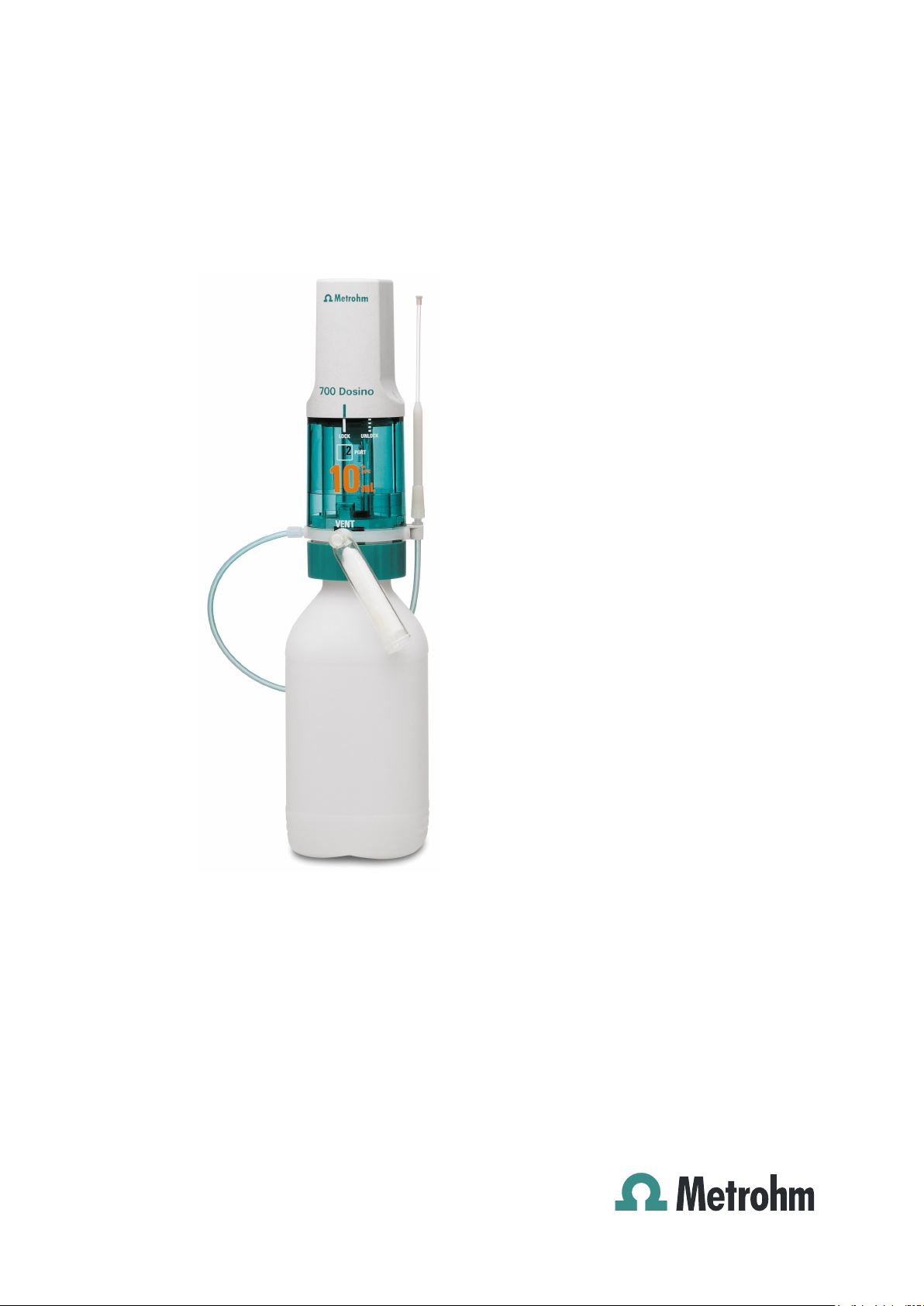
700 Dosino
8.700.1023
Manual
03.2000 dm
Page 4

Teachware
Metrohm AG
CH-9101 Herisau
teachware@metrohm.com
This documentation is protected by copyright. All rights reserved.
Although all the information given in this documentation has been
checked with great care, errors cannot be entirely excluded. Should you
notice any mistakes please send us your comments using the address
given above.
Documentation in additional languages can be found on
http://products.metrohm.com under Literature/Technical documenta-
tion.
Page 5

Contents
1 Overview _____________________________________________1
1.1 Areas of application ____________________________ 1
1.2 Application possibilities _________________________ 2
1.2.1 The Dosino as a system component ...........................3
1.3 Construction of the Dosino burets ________________ 3
1.3.1 The 700 Dosino dosing drive.......................................3
1.3.2 The 710 Dosing unit....................................................4
2 Setup _________________________________________________5
2.1 700 Dosino dosing drive_________________________ 5
2.1.1 Connecting to a control instrument..............................5
2.1.2 Safety information.......................................................6
2.2 710 Dosing unit ________________________________ 7
2.2.1 Mounting the dosing units ...........................................7
2.2.2 Placing the drive on the 710 Dosing unit.....................9
2.2.3 Problems in attaching the dosing drive?....................10
2.2.4 Removing the dosing drive from the 710 Dosing unit 11
2.3 Dismantling the dosing units ____________________ 12
2.3.1 Opening the housing.................................................13
2.3.2 Centering tube and glass cylinder .............................14
2.3.3 Centering tube and ETFE cylinder ............................16
2.4 Assembling the dosing units ____________________ 17
2.4.1 ETFE cylinder............................................................20
2.5 Dosino and dosing unit setup ___________________ 21
2.5.1 Support mounting (6.2047.010).................................21
2.5.2 Double bottle holder (6.2055.100).............................21
2.5.3 727 Ti Stand (2.727.0XXX) .......................................22
2.5.4 Direct mounting on canisters.....................................22
3 The Dosino in practice_____________________________ 23
3.1 Air bubbles are (almost) inevitable _______________ 26
3.2 Reagent exchange_____________________________ 27
3.3 Cleaning and maintenance______________________ 28
3.3.1 Cleaning the cylinder and piston ...............................28
3.3.2 Cleaning the stopcock washer and distributor disk....29
3.4 Troubleshooting / Problems_____________________ 31
3.4.1 Dosino buret..............................................................31
3.4.2 Dosing unit................................................................33
3.4.3 Dosing drive..............................................................35
3.4.4 Dosing.......................................................................35
700 Dosino, Instructions for Use
Page 6

Contents
4 Appendix ____________________________________________37
4.1 Validation / GLP _______________________________37
4.2 Dosing accuracy according to ISO 8655-3__________38
4.3 Technical data_________________________________40
4.4 Warranty and Conformity________________________42
4.4.1 Warranty ...................................................................42
4.4.2 EU Declaration of Conformity....................................43
4.4.3 Declaration of Conformity..........................................44
4.5 Accessories___________________________________45
5 Index ________________________________________________48
700 Dosino, Instructions for Use
Page 7
1 Overview
1.1 Areas of application
The Metrohm 700 Dosino is a versatile dosing drive which can be
used for a wide range of demanding dosing tasks. It can be operated with various control instruments; this predestines it for use in
complex automated systems.
1.1 Areas of application
Thanks to different 710 Dosing units (buret
units) with 2, 5, 10, 20 or 50 mL dosing
cylinders the Metrohm 700 Dosino is suitable for flexible use as a buret and can be
adapted to a wide range of different applications.
The 700 Dosino can be placed directly
on the reagent bottle. A range of
threaded adapters ensures optimal
fitting on the various types of bottle and
threads. The size of the container is no
longer important.
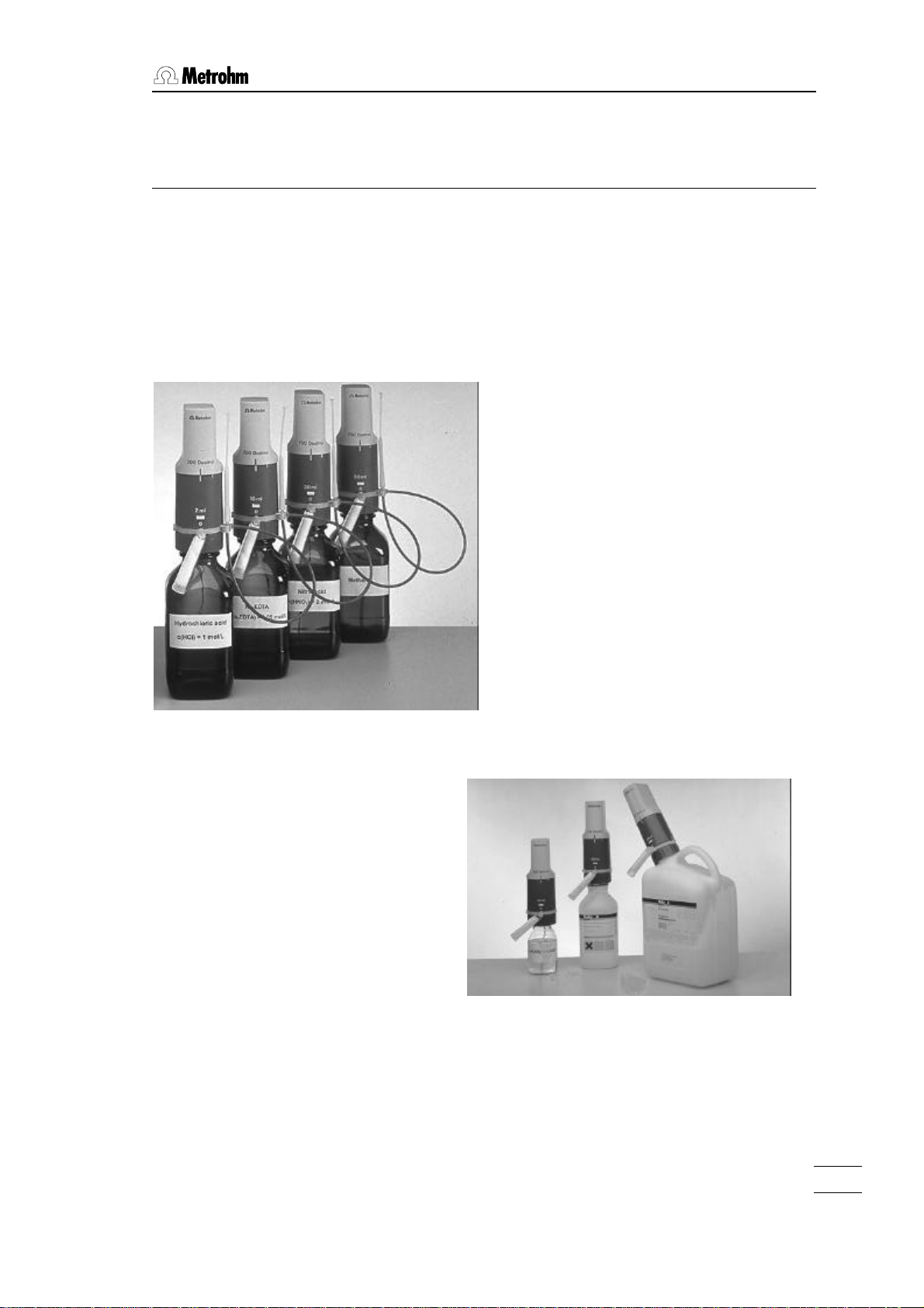
This type of assembly not only means
that a lot of space is saved but, because the reagent is located below the
drive, no escaping liquid can damage
the drive.
Instead of the standard glass cylinder,
dosing cylinders made of plastic (ETFE)
are also available for use with aggressive
alkalis.
Reagent exchange with the least possible
loss of reagent is ensured as the design of
the dosing unit has been optimized to provide the smallest possible dead volume.
700 Dosino, Instructions for use
1
Page 8
1. Overview
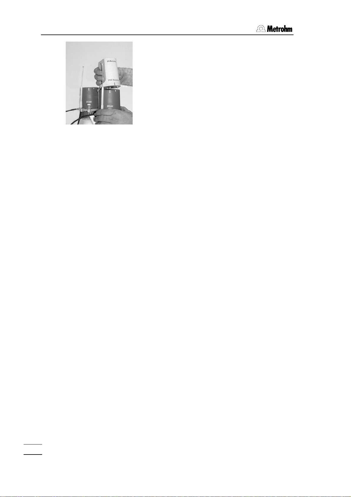
If reagents are exchanged frequently then the
dosing unit can remain attached to the reagent bottle while the dosing drive is simply
removed and attached to the next dosing
unit.
1.2 Application possibilities
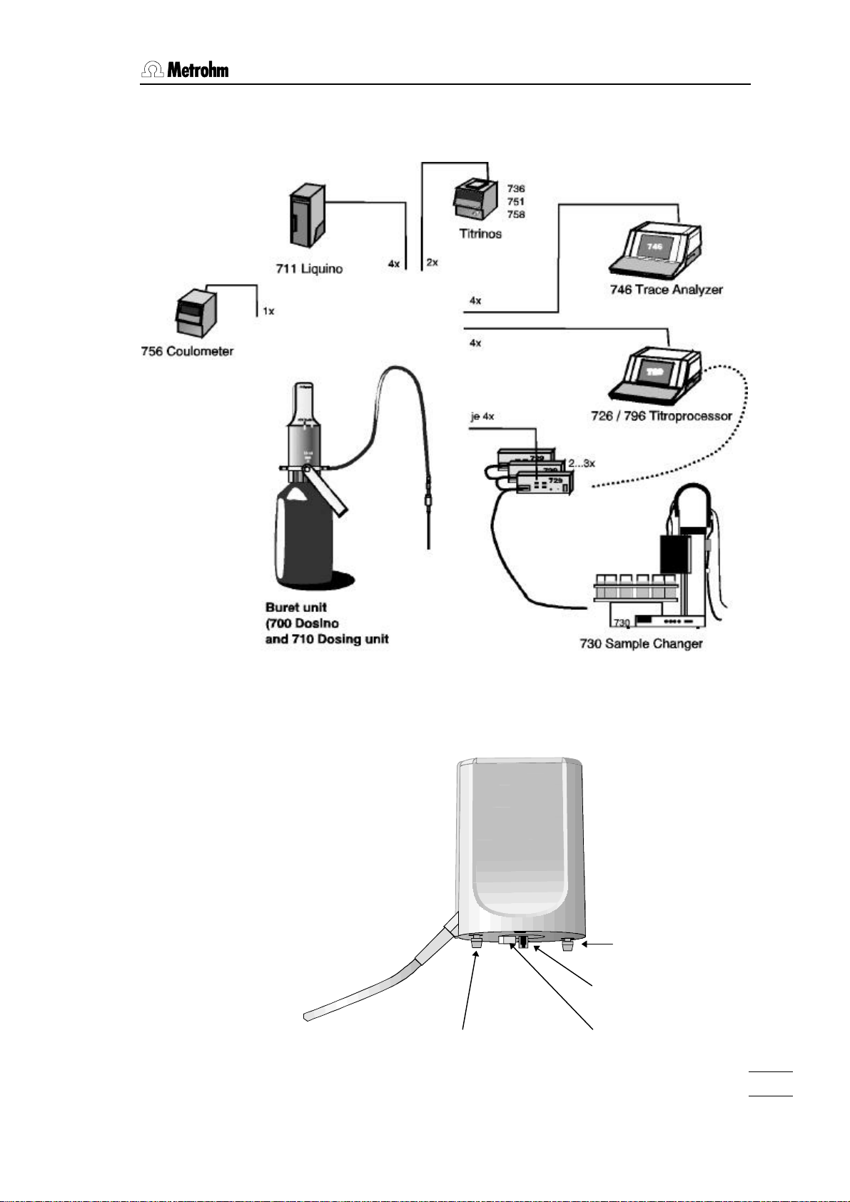
700 Dosino dosing drives are supported by various Metrohm instruments and are suitable for a wide range of different applications.
Titration
The following Metrohm titrators can control 700 Dosinos as titration burets:
• 726/796 Titroprocessor (connection for four Dosinos as standard; can be extended for up to twelve Dosinos * )
• 736 GP–Titrino (connection for two Dosinos)
• 751 GPD–Titrino (connection for two Dosinos)
• 758 KFD–Titrino (connection for two Dosinos)
Dosing
For complex dosing tasks, such as dosing controlled by time,
dosing rate or temperature, the preparation of standard solutions
and dilutions as well as pipetting or sample preparation the Dosino
can be used with the
• 711 Liquino
As auxiliary buret the 700 Dosino can be used with e.g. the following Metrohm instruments:
• 730 Sample changer (connection for up to twelve Dosinos * )
• 756 KF–Coulometer (connection for one Dosino)
• 746 Trace analyzer (connection for four Dosinos)
• 726 Titroprocessor (connection for four Dosinos as standard;
can be extended for up to twelve Dosinos * )
• 736 GP–Titrino (connection for two Dosinos)
• 751 GPD–Titrino (connection for two Dosinos)
• 758 KFD–Titrino (connection for two Dosinos)
*
Four Dosinos can be connected to the external bus of the control instrument via
a 729 Dosimat Interface. Up to three 729 Dosimat Interfaces can be operated in
cascade form on a single external bus.
2
700 Dosino, Instructions for Use
Page 9
1.3 Construction of the Dosino burets
1.2.1 The Dosino as a system component
1.3 Construction of the Dosino burets
1.3.1 The 700 Dosino dosing drive
guide cam
700 Dosino, Instructions for use
guide cam
push rod
carrier
3
Page 10
1. Overview
6.1573.XXX
ceramics)
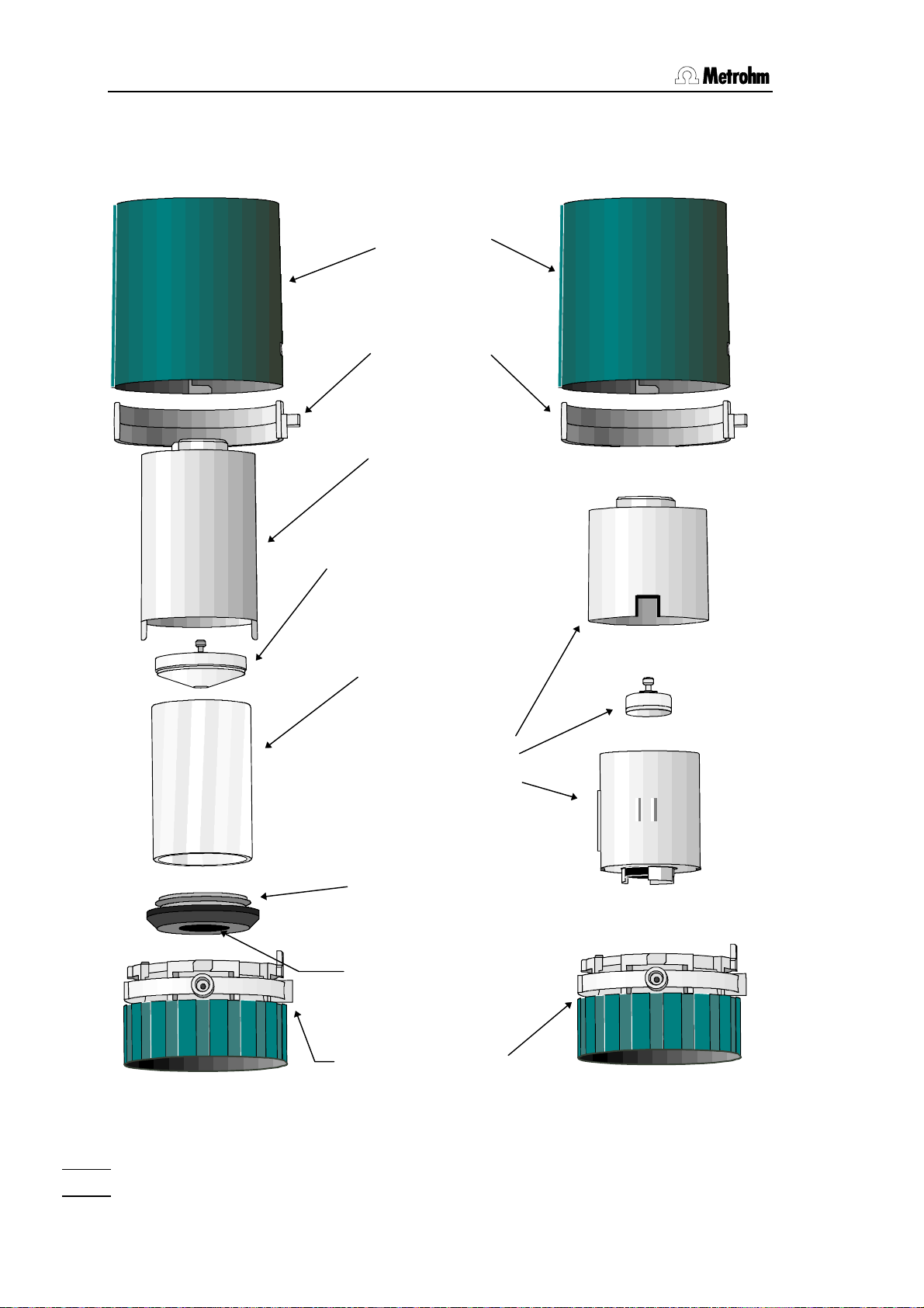
1.3.2 The 710 Dosing unit
710 Dosing unit
with glass cylinder
710 Dosing unit
with ETFE cylinder
Housing
(PBTP)
Spring clip
(PBTP)
Centering tube
(PVDF)
Dosing piston
with piston peg
(PTFE and graphite),
6.1572.XXX
(for glass cylinder)
Glass cylinder
(borosilicate glass)
6.1571.XX
ETFE dosing cylin-
der, complete with
piston and stopcock
washer 6.1566.XXX
Cylinder base
(PTFE/graphite)
Stopcock washer
(silicon carbide
Distributor with
distributor disk
(PVDF/ETFE)
4
700 Dosino, Instructions for Use
Page 11
2 Setup
2.1 700 Dosino dosing drive
Checks
Please check immediately on receipt whether the shipment is
complete and undamaged (compare with delivery note and list of
accessories in section 4.4). If transport damage has occurred
please refer to section 4.3 'Warranty'.
Location
The 700 Dosino is a robust instrument and can therefore be used
under rough conditions in laboratories and factories.
However, care must be taken that it is not exposed to a corrosive
atmosphere. Regular care of the instrument is essential if it is
used under rough conditions.
2.1 700 Dosino dosing drive
If an instrument which has been stored under cold conditions is
brought into a warm room then it is possible that the atmospheric
humidity could cause water to condense inside the instrument. In
order to avoid damage to the instrument it should be allowed to
acclimatize itself for at least one hour before it is switched on.
2.1.1 Connecting to a control instrument
The 700 Dosino is supplied with one of two different plugs. Please
check that your model is fitted with the correct plug.
• Model 2.700.0010 with 9-pin plug (DB9)
for connection to the following instruments:
− 726 Titroprocessor
− 729 Dosimat Interface (for connection to 730 Sample
Changer or 726 Titroprocessor)
− 693 VA Processor
− 746 Trace Analyzer
− 695 Autosampler
The 6.2134.010 Adapter cable can be used for connecting Model
2.700.0020 (mini-DIN plug) to the instruments listed above.
700 Dosino, Instructions for Use
5
Page 12
2. Setup
• Model 2.700.0020 with mini-DIN plug
for connection to the following instruments:
− 711 Liquino
− 736, 751, 758, 784, 785 Titrinos
− 756 KF–Coulometer
The 6.2134.020 Adapter cable can be used for connecting Model
2.700.0010 (DB9-plug) to the instruments listed above.
The location of the correct connection socket for the Dosino can
be found in the ‘Instructions for Use’ of the corresponding control
unit.
Only connect the Dosino to a control instrument when this is
switched off. The control instrument only recognizes the
Dosino during the switching-on process.
Please note the arrangement of the connection sockets. Do
not try to plug in the connection cable by using force!
2.1.2 Safety information
General:
This instrument left our factory in perfect condition from a safety
point of view (see technical data, safety specification). The following information must be carefully observed in order to maintain this
condition and to ensure hazard-free operation.
Connection to a control instrument:
This instrument must only be connected to that connection socket
of a Metrohm instrument which is provided for it (see corresponding ‘Instructions for Use’). Only those adapter cables listed in the
instructions are to be used.
Repairs and maintenance:
If faults or malfunctions occur during the operation of the 700
Dosino it is recommended that the connections with the control instrument are first checked to see if they are correct.
The Dosino (dosing drive) must not be opened. This should
only be carried out by authorized service personnel.
6
700 Dosino, Instructions for Use
Page 13
2.2 710 Dosing unit
Checks
Please check immediately on receipt whether the shipment is
complete and undamaged (compare with delivery note and list of
accessories in section 4.5). If transport damage has occurred
please refer to section 4.4 'Warranty'.
2.2.1 Mounting the dosing units
Dosing units are available with different cylinder volumes from 2 to
50 mL (see accessory list, p. 45). Dosing units with glass cylinders
(ordering no. 6.3031.XXX) are available for standard applications
such as dosing and titrating with non-aggressive solutions. For
dosing aggressive media such as strong alkalis we recommend
the use of dosing units with ETFE cylinders (ordering no.
6.3030.XXX). Dosing units must be ordered separately.
Standard situation
Dosing units can be mounted directly on reagent bottles with a
GL45 thread. Suitable threaded adapters are available for bottles
from different chemical manufacturers (see accessories list, p. 45).
2.2 710 Dosing unit
• First attach the 6.2052.000 Buret tip holder to the white plastic
ring of the dosing unit. Insert the double web of the holder into
the upper edge of the ring until it reaches the notch and then,
using a little pressure, carefully tilt the buret tip holder downwards until the individual webs snap into the lower edge of the
ring. A buret tip can now be suspended from the holder with the
tip facing upwards.
Buret tip holder
• Screw the 6.1829.010 Aspiration tubing tightly onto the
threaded connection on the lower surface of the dosing unit.
This is the filling port (Dosino Port 2). Make care that the tubing
is attached tightly so that no air bubbles can penetrate when
the reagent solution is aspirated. Tighten the screw nipple firmly
by hand.
700 Dosino, Instructions for Use
7
Page 14

2. Setup
If it is not possible to loosen a connection nipple by hand then
you should use the 6.2739.000 Spanner supplied. Using the
spanner to tighten up a nipple can damage the tubing connection.
• Place the dosing unit on the reagent bottle and screw it down.
Tighten the fixing ring (on the distributor) firmly. It is now possible to rotate the upper part of the housing in any direction you
require.
If the thread does not fit then you must use a threaded adapter,
see p. 45.
• Fill the 6.1619.000 Adsorber tube with a suitable adsorption
material for the reagent, e.g.
− Molecular sieve for moisture-sensitive solutions such as
KF solutions or others.
− Soda lime for sodium hydroxide (CO2 adsorption)
• Screw the adsorber tube onto connection port 0 of the dosing
unit. Port 0 vents the reagent bottle. It should never be closed
completely. If no adsorber tube is required then Port 0 must
remain open.
• Mount the 6.1805.100 Dosing tubing on Port 1 of the dosing
unit. Tighten the connection nipple by hand.
• Depending on the application you can now screw the
6.1543.050 Titrating tip with anti-diffusion valve or the
6.1543.060 Dosing tip onto the dosing tubing. The 6.1446.030
Ball stopper supplied can be used to fix the tip in an NS14/15
ground joint opening.
8
700 Dosino, Instructions for Use
Page 15

2.2.2 Placing the drive on the 710 Dosing unit
Check the positions of the centering tube and dosing
piston of the dosing unit.
centering tube with
housing
rib on rib
recess
• The plastic rib in the recess of the centering tube must be flush with the plastic rib
on the dosing unit housing (rib on rib).
• If necessary rotate the centering ring by
hand until the rib on rib position is obtained.
• Check the piston peg. It has to be flush
with the upper edge of the dosing unit. If
this is not the case, see chapter 2.2.3,
next page
piston peg
2.2 710 Dosing unit
guide cams
Check the position of the carrier disk of the drive.
rib on rib
push rod
carrier on carrier disk
• The plastic rib of the carrier disk must be
flush with the plastic rib on the base plate
of the drive (rib on rib).
• If necessary rotate the centering ring by
hand until the ribon rib position is obtained.
Please note!
The dosing drive carrier can only be ad-
justed when the control instrument to
which it is connected is switched off.
700 Dosino, Instructions for Use
9
Page 16
2. Setup
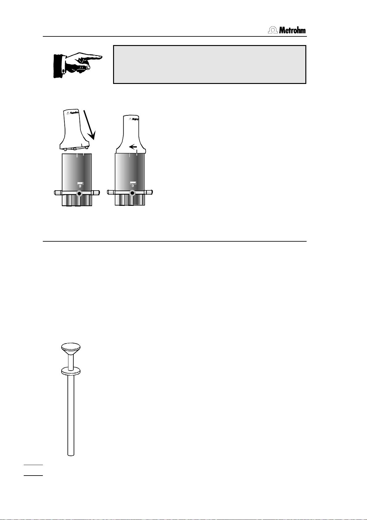
Never use force when attaching the dosing
drive!
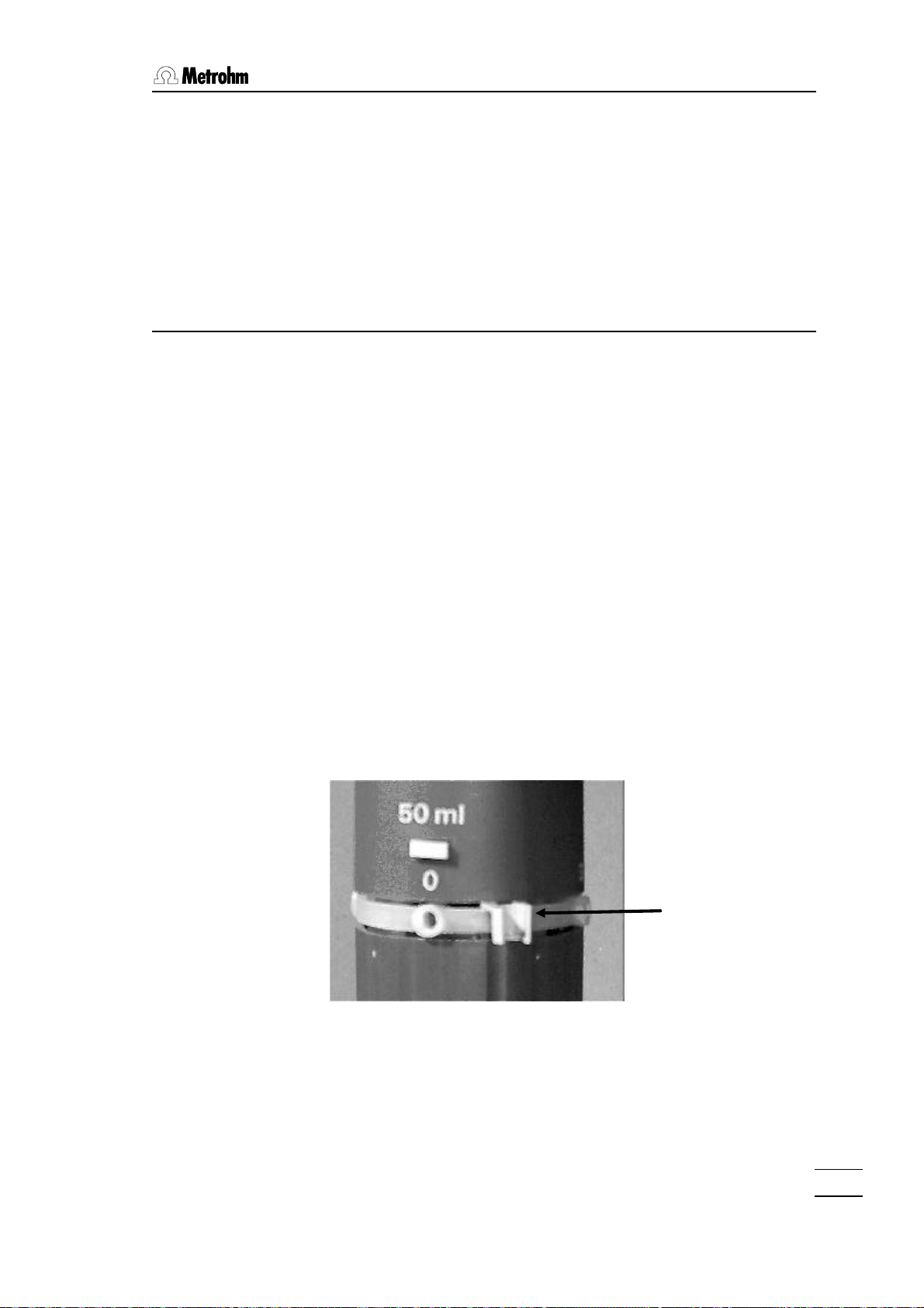
• Place the dosing drive (700 Dosino) on the
710 Dosing unit.
The green line on the Dosino must coin-
cide with the short white marking of the
dosing unit; see accompanying diagram.
n
o
i
s
D
o
0
7
0
The guide cams of the Dosino must be located in the openings provided for them.
• Lock the drive, i.e. turn to the left
(counterclockwise) until the stop is
10 ml
10 ml
reached.
The green line on the Dosino must now
coincide with the long white marking of
the dosing unit; see accompanying diagram.
2.2.3 Problems in attaching the dosing drive?
If the dosing unit cannot be attached then either the stopcock
washer of the Dosino or the centering tube of the dosing unit may
not be in the exchange position.
The stopcock washer carrier must fit in the dosing unit recess
provided for it. Please consult the previous diagrams.
The peg of the piston must be flush with the upper
edge of the dosing unit.
How to adjust the dosing piston:
Each Dosino is supplied with piston pliers (6.1546.030); see
accompanying diagram.
• Press the white knob of the piston pliers. Two wire loops appear at the piston pliers tip.
• Position the piston pliers so that these wire loops surround the
piston peg.
• If you now release the knob carefully the piston pliers will snap
shut and you can pull out the piston with the white knob (some
force is required).
10
Take care with the 2 mL cylinder! In contrast to the larger
dosing cylinders it is possible to pull out the piston completely.
You should only pull out this piston so far (and carefully) that
700 Dosino, Instructions for Use
Page 17
2.2 710 Dosing unit
the gray upper edge of the dosing piston is just visible.
• Release the piston pliers by pressing the white knob.
• Then press the inverted dosing unit against a flat surface. The
piston should now be flush with the upper edge of the dosing
unit.
2.2.4 Removing the dosing drive from the 710 Dosing unit
A dosing drive can only be removed from a dosing unit
when the four-way valve is in Position 2 (filling port,
exchange position).
• Press the <EXCH>, <FILL> or [Fill] key on the control instru-
ment. The valve will automatically turn to the 'Exchange' position.
Detailed information about the manual operation of Dosinos can
be found in the ‘Instructions for Use’ of your instrument.
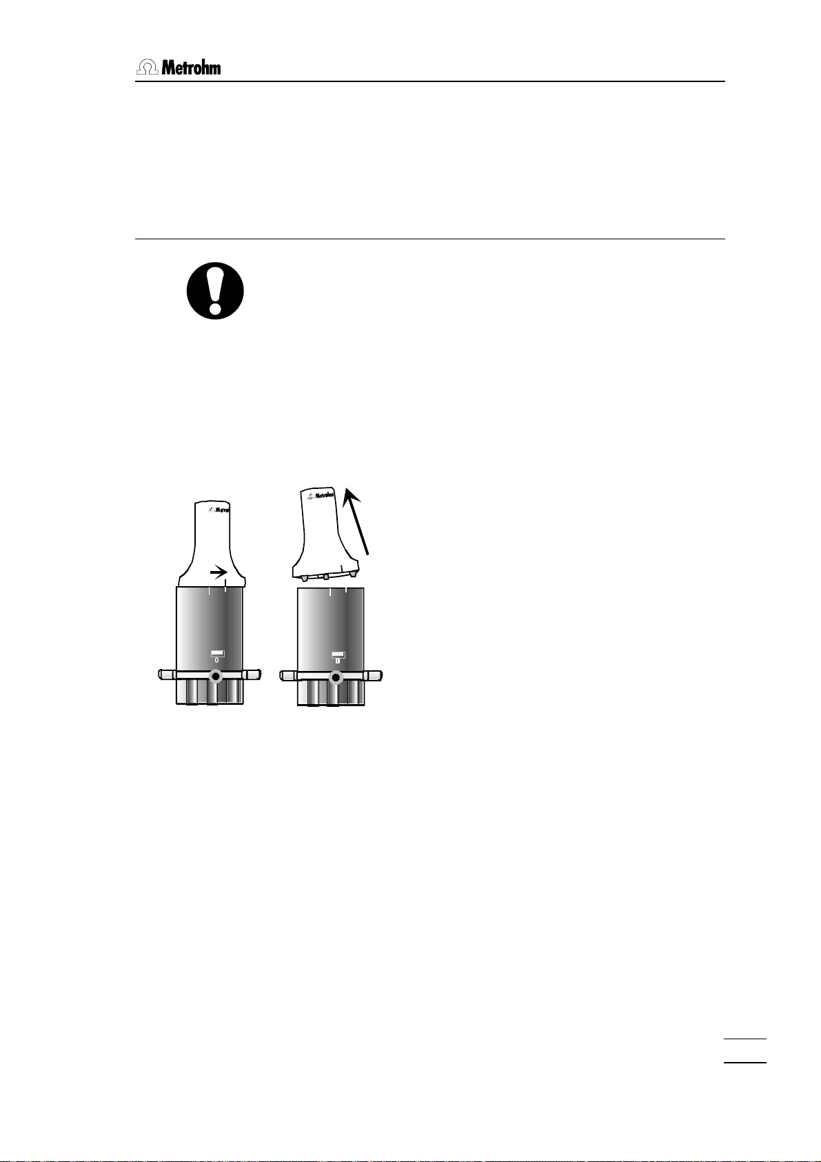
10 ml
• The drive mounted on the dosing unit is
unlocked by rotating the Dosino to the
right (clockwise).
n
o
i
s
D
o
0
7
0
The green line on the Dosino must now
coincide with the shorter white marking of
the dosing unit.
• The dosing drive can now be lifted off up-
10 ml
wards.
• Never adjust the carrier of the Dosino or
the centering tube of the dosing unit when
these have been separated from each
other. This could make attaching the dosing unit more difficult; please refer to the
explanations on the previous page.
700 Dosino, Instructions for Use
11
Page 18

2. Setup
2.3 Dismantling the dosing units
Dosing unit with
glass cylinder
Dosing unit with
plastic cylinder
Housing
Centering
tube
Dosing cylin-
der with pis-
ton and stop-
cock washer
12
Distributor
Distributor disk
with 4 Port
connections
700 Dosino, Instructions for Use
Page 19

It is not normally necessary to dismantle the dosing unit when
changing the reagent. Owing to the minimal exchange volume of
only a few microliters and the 'EMPTY' and 'PREP' functions,
which each control instrument possesses for the Dosino, the reagent in a dosing unit can be comfortably exchanged without much
loss of reagent; please refer to chapter 3.2.
Check the piston and cylinder of a dosing unit regularly (i. e. twice
per year), see chapter 3.3. If alkaline, corrosive or concentrated
reagents are used then a shorter interval should apply as the
glass cylinder could be attacked by aggressive alkalis or crystals
may be formed. We also recommend that dosing units with ETFE
cylinders are used for alkaline reagents.
• You should empty the cylinder before opening a dosing unit by
using the 'EMPTY' function of the control instrument.
2.3.1 Opening the housing
The internal construction of a dosing unit with an ETFE cylinder is
different from that of a dosing unit with a glass cylinder. Dismantling a dosing unit with a glass cylinder is described below. Points
which have to be taken into account when dismantling a dosing
unit with an ETFE cylinder are mentioned on page 16.
2.3 Dismantling the dosing units
• First remove the dosing drive; see chapter 2.2.4.
• Remove all tubing and the drying tube from the dosing unit. In
order to remove the drying tube press the rotating axis of the
tube firmly and turn it counterclockwise until the screw nipple is
loose.
If the dosing unit is mounted on a reagent bottle screw it off and
remove the filling tube.
• Place the dosing unit on a flat surface so that
the marking showing the volume is facing towards you.
700 Dosino, Instructions for Use
13
Page 20

2. Setup
distributor
• Keep the white knob pressed down and rotate
the dosing unit housing by approx. 1 cm to the
right (counterclockwise).
• Release the white knob and carefully lift the
housing upwards.
• Take care that the white spring clip inside the
housing does not slip out of place.
2.3.2 Centering tube and glass cylinder
piston peg
• You can now see the centering tube, which rotates together with the internal cylinder on the
distributor.
• Remove the centering tube.
• The centering tube is plugged
onto the black cylinder base.
Loosen it carefully from the
cylinder base.
• Take care that the black cylinder base is also
lifted up.
centering tube
piston with
piston peg
dosing cylinder
cylinder base
14
700 Dosino, Instructions for Use
Page 21

piston pliers
2.3 Dismantling the dosing units
Use the piston pliers (6.1546.030) to pull the
dosing piston out of the cylinder:
• Press the white knob of the piston pliers.
Two wire loops appear at the piston pliers tip.
• Position the piston pliers so that these wire
loops surround the piston peg.
If you now release the knob carefully the piston
pliers will snap shut and you can pull out the piston
with the white knob (some force is required).
dosing piston
• The glass cylinder can now be
removed from the cylinder
base by twisting it firmly.
Leave the black stopcock washer
in the cylinder base.
You can now clean or replace the individual components, such as
the cylinder or the piston.
See chapter 3.3 for cleaning instructions.
Please note! It makes no sense to replace the cylinder or the pis-
ton separately. Always replace both, if necessary.
dosing cylinder
cylinder base
with stopcock
washer
(lower side)
700 Dosino, Instructions for Use
15
Page 22

2. Setup
2.3.3 Centering tube and ETFE cylinder
In a dosing unit with an ETFE cylinder the centering tube consists
of two plastic parts. The dosing cylinder is integrated in the lower
plastic part.
• Open the housing as described in section 2.3.1.
• Lift off the centering tube in one piece (i.e. both plastic parts)
from the distributor.
• The upper plastic part can simply be pulled off
upwards.
You can now see the plastic cylinder with the
dosing piston.
• The dosing piston can be removed with the piston pliers in
the same way as for a glass
cylinder, see section 2.3.2.
Leave the black stopcock washer
in the cylinder base.
16
700 Dosino, Instructions for Use
Page 23

2.4 Assembling the dosing units
Several important points must be observed when assembling the
dosing units.
The dosing cylinder and piston, in particular its
sealing lips, must not be damaged in the assembly
process.
• Place the black cylinder base with the stopcock
washer facing downwards on a flat surface.
Place the glass cylinder on it as nearly verti-
cal as possible and press it gently and as
uniformly as possible onto the cylinder base
while moving it backwards and forwards slightly.
Do not tilt!
• Check whether the glass cylinder is seated
properly on the cylinder base.
2.4 Assembling the dosing units
• Place the dosing piston on the cylinder as nearly
horizontal as possible.
• Insert the dosing piston as uniformly as possible
into the cylinder. Hold the outer edge of the
piston between the left and right index fingers
(for larger diameter cylinders use the middle fingers as well) and carefully press the piston into
the glass cylinder with uniform pressure.
• The upper edge of the sealing lip must be flush
with the cylinder rim, see photo.
700 Dosino, Instructions for Use
17
Page 24

2. Setup
• You can now attach the centering tube.
The narrow and the wider web on the lower
surface of the centering tube must fit into the
corresponding recesses of the black cylinder
base.
The head of the piston push rod must fit into the
opening on the top of the centering tube.
• Press the centering tube firmly onto the cylinder
base.
• The centering tube with cylinder and cylinder
base is now attached to the distributor.
The centering tube must be correctly positioned
in order to assemble the housing.
• Rotate the centering tube on the distributor so
that the marking rib on the centering tube coincides with the marking rib on the distributor rim
(see photo alongside), i.e. rib on rib.
rib
• Before attaching the green housing check
whether the internal gray spring clip is positioned properly in its guide groove and can be
easily moved by applying pressure to its projecting knob.
• Now place the dosing unit housing over the
centering tube. The alignment is again rib on
rib, see photo alongside.
18
Make sure that the centering tube fits into the
opening on the top of the housing.
rib
700 Dosino, Instructions for Use
Page 25

2.4 Assembling the dosing units
• Lock the housing by turning it to the left
(clockwise).
Hold the distributor tightly. Do not use force!
If all the parts fit together properly the housing
will snap into place.
• Now check that the piston and the centering
tube are positioned correctly.
The head of the piston must be flush with the
upper edge of the housing.
rib
• Use the piston pliers to pull out the piston until
the stop is reached and press the complete inverted dosing unit onto a flat surface.
rib
• Check the valve setting.
You can recognize the recess for the carrier of
the Dosino on the top of the dosing unit, see
photo.
In this recess you will again see two marking
ribs.
• Rotate the centering tube until these ribs coincide.
• Refit all tubing and the adsorber tube.
700 Dosino, Instructions for Use
19
Page 26

2. Setup
2.4.1 ETFE cylinder
• Insert the dosing piston into the cylinder as described in the previous section.
recess
double rib
• The centering tube for the plastic cylinder has a
recess on its lower surface.
• Place the centering tube on the lower part of the
cylinder so that the recess encloses the double
rib on the outside of the lower part.
• Just as for the dosing unit with glass cylinder,
care must be taken that the marking ribs on the
distributor coincide with those on the outside of
the cylinder when placing the complete plastic
part on the distributor.
• The housing can now be attached in the same
way as described for the dosing unit with glass
cylinder.
20
⇐ Exception:
The 50 mL ETFE cylinder is similar in construction
to the glass cylinders and is assembled similarly.
700 Dosino, Instructions for Use
Page 27

2.5 Dosino and dosing unit setup
2.5 Dosino and dosing unit setup
Various stands and holding devices are available for Dosino burets:
2.5.1 Support mounting (6.2047.010)
• Attach the support
mounting to a support
rod (10 mm dia.)
• Place the dosing unit
(without bottle) in the
mounting from above.
Screw the reagent bottle
onto the dosing unit from
below.
2.5.2 Double bottle holder (6.2055.100)
• The double bottle holder can be adjusted in height.
Bottles up to 1 liter can be used.
• 2 inserts for sleeves can be used as buret tip or electrode holders.
• Version:
free stand assembly
700 Dosino, Instructions for Use
21
Page 28

2. Setup
2.5.3 727 Ti Stand (2.727.0XXX)
• For titrations in particular we recommend the use of
our 727 Ti Stand (with or without built-in magnetic
stirrer).
2.5.4 Direct mounting on canisters
• A Dosino with dosing unit can be directly
mounted on a canister with a suitable adapter.
Use 6.1618.050 Thread adapter.
22
700 Dosino, Instructions for Use
Page 29

3.1 Air bubbles are (almost) inevitable
3 The Dosino in practice
700 Dosinos can be connected to various control instruments.
They are used as dosing drives which can be operated with different 710 Dosing units. The dosing unit forms the buret and is
mounted directly on a reagent bottle or a canister.
Changing a dosing unit (and therefore a reagent) is very easy. The
drive is removed from one dosing unit with a single movement and
attached to the next one. The Dosino remains plugged into the
control instrument.
Before a Dosino buret is used we recommend that the dosing cylinder and the tubing are rinsed through once with reagent solution
in order to ensure that the whole system is bubble-free.
Metrohm instruments possess the comfortable 'PREP' function for
this important preparation step: a complete rinsing cycle is triggered by pressing a key.
700 Dosino
10 ml
10 ml 10 ml
10 ml
10 ml
If a dosing unit is to be filled with a different reagent then the dosing cylinder and connected tubing are first emptied with the
'EMPTY' function. The dosing unit is then filled by using the
'PREP' function .
700 Dosino, Instructions for Use
23
Page 30

3. The Dosino in practice
Port 2
4-way valve
Port 1
Port 2
4
1
dosing cylinder
3
Port 3
Port 4
Simplified functional diagram
• The dosing cylinder with the stopcock washer
in the cylinder base is coupled to the centering tube.
• The centering tube is loosely seated on a
distributor fitted with four different channels.
These channels lead to the different ports.
• The dosing drive with its carrier rotates the
centering tube and therefore the stopcock
washer. This results in movement to a particular valve setting.
• The dosing motor of the drive moves the
dosing piston by means of a push rod and in
this way ejects or aspires liquid from or into
the cylinder via the selected port.
Port assignment
The distributor of a dosing unit has freely addressable inputs/outputs (ports) and an additional connection (Port 0) which
leads directly to the lower surface of the distributor. This Port 0,
which cannot be addressed by the 4-way valve, is used for venting
the storage container and can be fitted with an adsorber tube.
Port 0
(venting the
bottle)
Port 1
Port 4
Port 3
24
Dosing unit distributor seen from below
700 Dosino, Instructions for Use
Page 31

3.1 Air bubbles are (almost) inevitable
The standard assignment listed below applies to the following
Metrohm instruments; it cannot be altered:
• 726 / 796 Titroprocessor
• 736, 751 and 758 Titrino models
• 746 VA Trace Analyzer
• 756 KF-Coulometer
The standard occupancy of the Dosino ports:
Port 1 Dosing outlet; M6 threaded connection on the left-hand
side of the housing.
The liquid is ejected via dosing or titrating tip.
Port 2 Filling inlet; M6 threaded connection on the bottom of
the dosing unit.
The liquid is aspired from a storage container.
Port 3 Not assigned; M6 threaded connection on the right-
hand housing side.
Port 4 Special functions; slender connection nipple on the
bottom of the dosing unit.
This can be used with the 'PREP' function for ejecting
the liquid. When emptying the dosing unit port 4 is
used as the air inlet.
Port 0 Venting the storage bottle; M6 threaded connection at
the front. A drying tube can be connected here; this
can be filled with e.g. molecular sieve or soda lime.
Variable port assignments are possible with the following instruments:
• 730 Sample changer (and successors)
• 711 Liquino
• 774 Oven Sample Processor
Ports 1 to 4 can be used bi-directionally here and are therefore
suitable for filling the dosing cylinder or dosing a liquid as required.
This means that complex liquid handling applications are possible.
If one of ports 1 to 3 is not in use then it should be closed
with a thread stopper (6.1446.040).
Never close Port 0 with a thread stopper when the dosing unit
is attached to a storage container. This could create a vacuum in the storage container – risk of implosion!
700 Dosino, Instructions for Use
25
Page 32

3. The Dosino in practice
3.1 Air bubbles are (almost) inevitable
As a result of leaky tubing connections or the release of dissolved
air from the liquid to be dosed it is possible that air bubbles could
collect in the dosing cylinder.
Always check the tubing ends for damage before you attach the
tubings. Please ensure that tubing connections are always tight.
Always tighten up the screw nipples firmly by hand and take care
that you do not damage the tubing ends when doing this.
All Metrohm instruments which support Dosinos as dosing drives
possess a 'PREP' function. This function is a preparation step in
which the cylinder and tubing are automatically filled with liquid.
In order for the control instrument to be able to calculate the correct amount of rinsing solution required it is necessary to enter the
lengths and diameters of all the connected filling and dosing tubing. This is carried out in the dosing unit configuration of the particular instrument.
Always use the 'PREP' function before you use a dosing unit
for the first time, i.e. before you start a sample series carry
out the 'PREP' function first (at least once per day).
Further details are given in the ‘Instructions for Use’ of your
Metrohm instrument.
Please note:
With the 'PREP' function the existing cylinder contents are completely ejected. The piston moves beyond the normal maximum
position (10'000 impulses) and presses against the cylinder base.
The piston can never completely fill the whole of the cylinder base
so that a small air bubble may remain in position.
Even after a 'PREP' preparation step there will
always be a small air bubble at the piston. It
will not escape the cylinder.
However, such a small air bubble does not af-
fect the precision of a dosing process!
For details please refer to the drawing on the following page.
26
700 Dosino, Instructions for Use
Page 33

3.2 Reagent exchange
zero position
(0 impulses)
max. position
air
bubble
(10'000 impulse)
PREP position
3.2 Reagent exchange
Dismantling and cleaning the dosing unit when a regent is
changed is not normally necessary. The dosing unit is constructed
so that only a small exchange volume is present.
• Empty the dosing unit with the 'EMPTY' function of the control
instrument.
The maximum position of the piston is
never exceeded in dosing processes.
The remaining dead volume is therefore
always larger than any air bubble which
may remain after the 'PREP' function
has been carried out. This means that it
cannot escape into the tubing system
and affect the precision of the dosing
process. The air bubble remains in the
dosing cylinder.
When the dosing unit has been emptied (with the 'EMPTY' function of the control instrument) it can be rinsed directly with the new
reagent.
• Fill the dosing unit with the 'PREP' function of the control in-
strument.
If precipitation or chemical reactions could occur when the new
reagent is mixed with the old one then an intermediate rinsing
stage should be carried out with an inert solvent.
If a reagent is not to be used for longer than one week then the
dosing unit should be emptied by means of the 'EMPTY' function
and the dosing drive removed.
700 Dosino, Instructions for Use
27
Page 34

3. The Dosino in practice
3.3 Cleaning and maintenance
Unlike the dosing units the dosing drive requires no special maintenance. You should ensure that it is not exposed to excessive dirt
or corrosive influences. If aggressive reagents are dosed with
Dosino burets then, when the dosing unit is not in use, it should be
rinsed with an inert solvent ('PREP' function) and then emptied
('EMPTY' function). The dosing drive should be removed during
longer periods (more than one week) of non-use .
Dosing units require to be checked regularly and be cleaned
frequently.
If alkaline, corrosive or concentrated reagents are used then a
check has to be done once a month or even once a week. Other
reagents may allow the inspection period to be extended to six or
twelve months.
The way in which a dosing unit is dismantled is shown on page
13ff.
3.3.1 Cleaning the cylinder and piston
• Check the tightness of the dosing piston and cylinder. If there is
liquid above the piston this means that the dosing cylinder is
either not lubricated at all or is not adequately lubricated. Check
whether the sealing lips are deformed or damaged; if they are
then the piston and the cylinder must be replaced.
• Clean the dosing cylinder and piston with a liquid detergent. Do
not use abrasive powders as these could scratch the cylinder.
Then thoroughly rinse the individual components with deionized
or distilled water.
• Degreasing the piston and the glass cylinder is part of the
cleaning process. Use an appropriate cleaning agent or solvent
and possibly an ultrasonic bath. Follow the manufacturer's recommendations.
• Before reassembling the dosing unit check the piston and cylinder again for changes. If the dosing cylinder is scratched or has
rough surfaces it must be replaced.
• In order to ensure that the Dosino buret does not leak it must
be slightly lubricated. Carefully apply a little 6.2803.000 Grease
(silicone-free) with your finger to the outside of the piston and
wipe off any excess grease with a soft lint-free cloth.
28
700 Dosino, Instructions for Use
Page 35

3.3 Cleaning and maintenance
3.3.2 Cleaning the stopcock washer and distributor disk
The stopcock washer and distributor disk must be checked
regularly. Blockages of the disk opening or the outlet ports
must be avoided at all costs.
Dismantle the dosing unit completely. The black stopcock washer
sits on the cylinder base and can be removed with a pair of forceps or a bent paper clip.
Stopcock washer
(in cylinder base)
Leave the white distributor disk in the distributor.
If the cock and distributor disks are stuck together they can be
separated in the following manner:
• Try to loosen the two disks by rotation.
• If this does not work place the two parts in water or an organic
solvent (i. e. ethanol) for a few minutes. It should now be possible to separate the disks by rotation.
Cleaning the stopcock washer and the distributor disk
• Use a liquid detergent. Abrasive powders are unsuitable and
could scratch the stopcock washer.
• Dry the disks with a lint-free soft cloth.
Distributor disk with 4 ports
(in distributor)
700 Dosino, Instructions for Use
29
Page 36

3. The Dosino in practice
Assembling the stopcock washer and distributor disk
• Insert the stopcock washer and press it down. The central
hole of the disk must point towards the cylinder base.
• Use a plastic pipet tip to extend the opening of the cylinder
outlet on the bottom of the cylinder base.
If the distributor disk was removed it can be reassembled as follows:
• Use a plastic pipetting tip to extend the opening of the distributor.
• Lightly grease the inner surfaces of the distributor disk with
6.2803.000 Grease (silicone-free).
• Mount the distributor disk on the distributor and press it down
tight. There is a central hollow on the disk. It has to be facing
upwards.
• Extend the opening with a plastic pipetting tip again.
30
700 Dosino, Instructions for Use
Page 37

3.4 Troubleshooting / Problems
3.4 Troubleshooting / Problems
3.4.1 Dosino buret
Dosing drive cannot be mounted on the dosing unit.
Possible causes:
• The carrier of the drive is in the wrong position.
⇒ Switch the control instrument off and then on again. If the car-
rier does not automatically rotate to the starting position
switch it off again and rotate the carrier manually to the correct position. Pay attention to the marking ribs: rib on rib. See
page 9.
• The centering tube is wrongly positioned.
⇒ Rotate the centering tube of the dosing unit into the correct
position by hand. Pay attention to the marking ribs: rib on rib.
See page 9.
• The dosing piston is in the wrong position. The piston peg
must be flush with the housing.
⇒ Use the piston pliers to pull out the piston to the stop (take
care with the 2mL buret) and press the inverted dosing unit
against a flat surface. See page 10.
• The push rod of the drive is wrongly positioned.
⇒ Place the drive on the empty housing of a dosing unit and
press <FILL> or <EXCH>.
Dosing drive cannot be removed from the dosing unit.
Possible causes:
• Piston and/or 4-way valve are not in the 'Exchange' posi-
tion.
⇒ Carry out 'EXCH' or 'FILL' function on the control instrument.
Check cable connections to control instrument.
⇒ Switch control instrument off and then on again.
⇒ Lock the drive on the dosing unit, i.e. turn it to the left until it
reaches the stop.
• If the dosing unit still cannot be removed after the 'EXCH'
or 'FILL' function has been carried out then either the piston or the 4-way valve is blocked or even damaged. Procedure:
1. Switch off control instrument.
2. Press the white knob of the dosing unit and remove the dis-
tributor. Place Dosino buret in an inverted position.
3. Switch on the control instrument and trigger EXCH or FILL. If
you can clearly hear the valve rotating the Dosino buret can
be replaced on the distributor.
700 Dosino, Instructions for Use
31
Page 38

3. The Dosino in practice
⇒ Place the dosing unit with attached drive vertically on the dis-
tributor, marking rib on marking rib, and turn the dosing unit to
the left until you can clearly hear the spring clip snap into position. You should now be able to remove the drive from the
dosing unit.
⇒ You can also directly dismantle the dosing unit by placing the
dosing buret without the distributor vertically on a flat surface
and removing the drive. If you now remove the dosing unit
housing the interior of the dosing unit with centering tube and
cylinder, etc. is freely accessible. Then reassemble the dosing
unit properly according to the instructions given on page 17ff.
If the valve cannot be rotated or if the piston does not move properly to the zero position then the dosing unit must be dismantled by a technician from your local Metrohm
service center.
If a dosing cylinder filled with a chemical is opened improperly this can damage the
dosing unit and/or the dosing drive.
The dosing drive housing must not be opened as the control electronics of the drive
are very susceptible to mechanical damage.
Dosino buret cannot be addressed by the control instrument.
Possible cause:
• Connection between Dosino and control instrument is in-
terrupted or the Dosino is in a faulty condition.
⇒ Check cable connections.
⇒ Switch control instrument off and on again.
⇒ Check the dosing and filling rates.
If this does not remedy the problem:
⇒ Contact your local Metrohm service center.
Control instrument does not recognize the Dosino buret.
Possible cause:
• Connection between Dosino and control instrument is in-
terrupted or the Dosino has not been initialized.
⇒ Check cable connections.
⇒ Switch control instrument off and on again.
⇒ If a 729 Dosimat interface is connected check its E-Bus ad-
dress.
If this does not remedy the problem:
⇒ Contact your local Metrohm service center.
32
700 Dosino, Instructions for Use
Page 39

The whole system is blocked.
Possible cause:
• The Dosino or control instrument is in an exceptional
faulty condition.
⇒ Check cable connections.
⇒ Switch control instrument off and on again.
⇒ Remove dosing drive from dosing unit. With the instrument
switched on check whether the drive carrier can be rotated.
– If yes then the dosing drive is faulty.
– If no then dismantle the dosing unit. Clean the black stop-
cock washer in the cylinder base, see page 29.
3.4.2 Dosing unit
Air bubbles in cylinder or dosing tubing
Possible causes:
• Leaking connections.
⇒ Check the tubing ends, in particular that of the aspiration tub-
ing.
⇒ Tighten all tubing connections manually.
⇒ Check whether the housing is properly locked. If necessary
remove the housing and then put it back on again.
3.4 Troubleshooting / Problems
• The reagent releases a lot of gas, i.e. dissolved air forms
bubbles.
⇒ Carry out PREP.
⇒ Lower the filling speed.
⇒ If necessary degas the reagent ultrasonically.
• Wear and tear.
⇒ Replace piston and/or cylinder.
• PREP not carried out or incorrect parameters.
⇒ Carry out PREP.
⇒ Correct tubing lengths and diameters.
Stopcock washer and distributor disk stick together
Possible cause:
• Precipitation of crystals from the reagent.
⇒ Clean the stopcock washer and distributor disk, see page 29.
700 Dosino, Instructions for Use
33
Page 40

3. The Dosino in practice
Dosing unit leaks from distributor
Possible cause:
• Leaky distributor disk.
⇒ Clean the stopcock washer and distributor disk, see page 29.
Liquid above the piston
Possible cause:
• Worn or faulty piston and/or cylinder.
⇒ Replace dosing piston and cylinder, see page 13.
Liquid drips into the bottle
Possible cause:
• Air in the cylinder.
⇒ Check the tubing ends, in particular that of the aspiration tub-
ing.
⇒ Tighten all tubing connections manually.
⇒ Check whether the housing is properly locked. If necessary
remove the housing and then put it back on again.
• The reagent releases a lot of gas, i.e. dissolved air forms
bubbles.
⇒ Carry out PREP.
⇒ Lower the filling speed.
⇒ If necessary degas the reagent, i. e. with helium, vacuum or
an ultrasonic bath.
• Wear and tear.
⇒ Replace piston and/or cylinder.
• PREP not carried out or incorrect parameters.
⇒ Carry out PREP.
⇒ Correct tubing lengths and diameters.
Dosing unit is not recognized or incorrectly recognized
Possible cause:
• Dosing drive not attached correctly.
⇒ Check whether the nominal volume on the dosing unit housing
is correct.
⇒ Remove Dosino and put it back on again.
34
⇒ Check whether the drive is correctly seated.
⇒ Switch control instrument off and on again.
⇒ If necessary contact your local Metrohm service center.
700 Dosino, Instructions for Use
Page 41

Housing cannot be closed
Possible cause:
• Spring clip inserted wrongly.
⇒ Remove housing and position spring clip correctly.
Dosing cylinder does not fit in centering tube.
Possible cause:
• Dosing cylinder jammed or tilted on cylinder base.
⇒ Dismantle cylinder and use tool to reassemble correctly.
Drying tube jammed.
⇒ Use your thumb or ball of thumb to press strongly on the ro-
tary axis of the drying tube and simultaneously turn the tube
counterclockwise carefully until the screw nipple becomes
loose.
3.4.3 Dosing drive
3.4 Troubleshooting / Problems
Drive carrier rotates continuously.
Possible cause:
• Dosino electronics damaged.
⇒ Send the dosing drive to your local Metrohm service center for
repair.
Dosino becomes hot.
Possible cause:
• Dosing drive is overloaded: 4-way valve or dosing piston is
blocked.
⇒ Switch off instrument immediately.
⇒ Dismantle dosing drive (please observe the information given
on page 31) and clean all the components. Replace any faulty
parts. See page 13ff.
3.4.4 Dosing
Reagent dosed from incorrect port
Possible cause:
• Control instrument configuration is wrong or incorrect pa-
rameters have been defined for the dosing unit.
⇒ Correct the settings; please refer to the ‘Instructions for Use’
of the control instrument.
700 Dosino, Instructions for Use
35
Page 42

3. The Dosino in practice
Tubing not completely filled during PREP.
Possible cause:
• Incorrect parameters have been defined for the dosing
unit.
⇒ Correct the tubing lengths and diameters; please refer to the
‘Instructions for Use’ of the control instrument.
Tubing not completely emptied during EMPTY.
Possible cause:
• Incorrect parameters have been defined for the dosing
unit.
⇒ Correct the tubing lengths and diameters; please refer to the
‘Instructions for Use’ of the control instrument.
Wrong volume is dosed.
Possible cause:
• Dosing unit mounted incorrectly or wrongly assembled.
⇒ Remove dosing unit and put it back on again.
⇒ Check whether the nominal volume on the housing coincides
with the effective cylinder volume.
Dosing does not take place.
Possible cause:
• Blocked tubing connections or dosing unit wrongly as-
sembled.
⇒ Check whether the dosing tip is blocked.
⇒ Check whether the dosing port has been closed with a thread
stopper.
⇒ Check whether Port 0 has been closed with a thread stopper
(vacuum in storage bottle!). Port 0 must be open to compensate the pressure.
⇒ Remove dosing drive and check whether the drive push rod
engages the dosing piston. The piston peg must be flush with
the upper side of the housing, see page 19.
36
700 Dosino, Instructions for Use
Page 43

4 Appendix
4.1 Validation / GLP
Among other things, GLP (Good Laboratory Practice) requires the
regular checking of the precision and correctness of analytical instruments by means of SOPs (Standard Operating Procedure).
Recommended literature
• Metrohm brochure "Quality management with Metrohm", de-
tailed information about the principles and procedures of Good
Laboratory Practice
• Metrohm Application Bulletin 238/1 "Dosimat test according to
GLP/ISO"
• Metrohm Application Bulletin 252/1 "Validation of Metrohm ti-
trators according to GLP/ISO9001"
4. Appendix
Dosino burets can be validated in several different ways.
• Metrodata «Dosing Test» software (6.6025.000) for Win-
dows® 3.11/95/NT
PC program for computer-controlled validation of Metrohm
dosing units and exchange units. Apart from a normal personal
computer this requires the use of a Metrohm Titrino and either
a Sartorius or Mettler analytical balance.
• Metrohm 711 Liquino
The 711 Liquino has a GLP mode which can be used for the
automatic validation of dosing units. The balances of the following distributos are supported: Mettler-Toledo, Sartorius,
AND, Precisa.
• Manual validation
Manual validation can be carried out with any Metrohm instrument which supports the 700 Dosino. Metrohm Application
Bulletin 238/1 describes the procedure in detail.
700 Dosino, Instructions for Use
37
Page 44

4.2 Dosing accuracy according to ISO 8655-3
4.2 Dosing accuracy according to ISO 8655-3
Metrohm Ltd. guarantees the following limits (according to ISO
8655-3, draft) for Dosino burets with glass cylinders:
Max. permissible systematic error e
Nominal
cylinder volume
in mL rel. abs.
2 ± 0,3 % ± 6 µL
5 ± 0,3 % ± 15 µL
10 ± 0,2 % ± 20 µL
20 ± 0,2 % ± 40 µL
50 ± 0,2 % ± 100 µL
a)
Expressed as deviation of the mean of a tenfold measurement
from any given volume in the range of 10 to 100 % of the nominal
volume.
ss VVe −=
Maximum permissible systematic errors es
or in %
=
s
100
( )
VsVse−
0
V
V : mean sV : selected volume 0V : nominal volume
Maximum permissible random error s
a)
Nominal
cylinder volume
in mL CV
2 ± 0,1 % ± 2 µL
5 ± 0,1 % ± 5 µL
10 ± 0,07 % ± 7 µL
20 ± 0,07 % ± 14 µL
50 ± 0,05 % ± 25 µL
b)
Expressed as coefficient of variation of a tenfold measurement
from any given volume in the range of 10 to 100 % of the nominal
volume.
s
100
CV
=
Maximum permissible random errors
repeatybility s
b)
s
c)
V
c)
Expressed as repeatability standard deviation of a tenfold measurement from any given volume in the range of 10 to 100 % of
the nominal volume.
38
700 Dosino, Instructions for use
Page 45

4. Appendix
s : repeatability standard deviation
2
( )
−
VV
n
i
1
−
∑
=
s
Please note
• The above-mentioned limits are related to water at 20 °C and
are valid for dosing units with glass cylinders only.
• The nominal volume of the dosing cylinders are printed on the
housing of the dosing units.
• The above-mentioned limits are valid for the useful volume range of 10 % to 100 % of the nominal volume.
• The error limits relate to the ISO 8655-3 Draft International
Standard (Piston-operated volumetric apparatus - part 3: Piston
burettes), which is to come to effect in the year 2000.
• Metrohm burets with glass cylinders in general have a better
quality performance (systematic and random error) than the
maximum error limits implied. Check your dosing system according to the ISO test specification.
Vi: distributed volume
n : number of distribution
Possible sources of dosing errors
Influencing parameters are:
• Air bubbles in the dosing cylinder or tubings.
• Leaky piston/cylinder system.
• Leaky tubing connections.
• Differences in hydrostatic pressure of the liquid level in the
supply flask versus the dosing tip.
• Viscosity and/or flow characteristics of the liquid to be dosed.
700 Dosino, Instructions for Use
39
Page 46

4.3 Technical data
4.3 Technical data
Dimensions Height: 200 mm
(Dosino with greatest diameter: approx. 95 mm
dosing unit)
Weight approx. 700 g (with dosing unit)
Material Dosino housing: PBTP (polybutyleneterephthalate)
Dosing unit housing: PVDF (polyvinylidenefluoride)
Dosing piston: PTFE (polytetrafluoroethylene)
Stopcock washer: silicon carbide ceramics
Distributor disk: Al2O3 ceramics
Cylinder volume exchangeable dosing units with cylinders of 2, 5, 10, 20, 50 mL
volume
Resolution 10'000 increments per cylinder volume
Dosing accuracy Metrohm Dosino burets with glass cylinders fulfill the performance
requirements of the ISO 8655-3 draft international standard:
Cylinder
volume
2 mL 0,2 µL ± 6 µL ± 2 µL
5 mL 0,5 µL ± 15 µL ± 5 µL
10 mL 1 µL ± 20 µL ± 7 µL
20 mL 2 µL ± 40 µL ± 14 µL
50 mL 5 µL ± 100 µL ± 25 µL
Dosing/Filling time 18 seconds each per cylinder volume
Power supply ±12 VDC, 5 VDC (from control instrument), 6 W
Ambient Nominal +5…+40°C
temperature working range (at 20…80% relative humidity)
Storage, transport -40…+70°C
Resolution Max. systematic
error
Repeatability
(random error)
Dosing connection Mini-DIN 8-pin or D-Sub 9-pin
40
700 Dosino, Instructions for use
Page 47

Safety specification
Constructed and tested according to IEC 1010, class 3
The ‘Instructions for Use’ contains information and warnings which
must be observed by the operator in order to ensure safe operation of the instrument.
Electromagnetic compatibility (EMC)
Emission This instrument meets the requirements of the standards EN
50081-1 01.92, EN 55011 (class B), EN 55022 (class B).
Immunity The following standards are complied with: EN 50082-2/94,
IEC801-2 to IEC801-4, EN 50082-1, IEC1000-4-4/95 level 3, IEC
1000-4-5, IEC 1000-4-6.
4. Appendix
700 Dosino, Instructions for Use
41
Page 48

4.4 Warranty and Conformity
4.4 Warranty and Conformity
4.4.1 Warranty
The warranty on our products is limited to defects that are traceable to material, construction or manufacturing error which occur
within 12 months from the day of delivery. In this case, the defects will be rectified in our workshops free of charge. Transport
costs are to be paid by the customer.
For day and night operation, the warranty is limited to 6 months.
Glass breakage in the case of electrodes or other parts is not cov-
ered by the warranty. Checks which are not a result of material or
manufacturing faults are also charged during the warranty period.
For parts of outside manufacture insofar as these constitute an
appreciable part of our instrument, the warranty stipulations of the
manufacturer in question apply.
With the regard to the guarantee of accuracy, the technical specifications in the instruction manual are authoritative.
Concerning defects in material, construction or design as well as
the absence of guaranteed features, the orderer has no rights or
claims except those mentioned above.
If damage of the packaging is evident on receipt of a consignment
or if the goods show signs of transport damage after unpacking,
the carrier must be informed immediately and a written damage
report demanded. lack of an official damage report releases
Metrohm from any liability to pay compensation.
If any instruments and parts have to be returned, the original
packaging should be used if at all possible. This applies above all
to instruments, electrodes, burette cylinders and PTFE pistons.
Before embedding in wood shavings or similar material, the parts
must be packed in a dustproof package (for instruments, use of a
plastic bag is imperative). If open assemblies are enclosed in the
scope of delivery that are sensitive to electromagnetic voltages
(e.g. data interfaces etc.) these must be returned in the associated
original protective packaging (e.g. conductive protective bag).
(Exception: assemblies with built-in voltage source belong in a
non-conductive protective packaging). For damage which arises
as a result of non-compliance with these instructions, no warranty
responsibility whatsoever will be accepted by Metrohm.
42
700 Dosino, Instructions for use
Page 49

4.4.2 EU Declaration of Conformity
The Metrohm Ltd. company, Herisau, Switzerland hereby certifies,
that the instrument:
700 Dosino
meets the requirements of EU Directives 89/336/EEC and
73/23/EEC.
Source of specifications:
EN 50081-1 Electromagnetic compatibility, basic specification
Emitted Interference
EN 50082-1 Electromagnetic compatibility, basic specification
Interference Immunity
EN 61010 Safety requirements for electrical laboratory
measurement and control equipment
4. Appendix
Description of the instrument:
Dosing drive with low dead volume for liquid handling such as dosing, liquid transfer, dilution etc.
Herisau, December 6, 1995
Dr. J. Frank Ch. Buchmann
Development Manager Production and
Quality Assurance Manager
700 Dosino, Instructions for Use
43
Page 50

4.4 Warranty and Conformity
4.4.3 Declaration of Conformity
The 700 Dosino was developed and manufactured in accordance with the requirements demanded by the ISO 9001 quality system regarding the design,
manufacture and servicing of Metrohm instruments.
Name of commodity: 700 Dosino
Manufacturer: Metrohm Ltd., Herisau, Switzerland
Technical specifications : source voltage: ±12 VDC, 5 VDC, 6 W
The instrument was manufactured and tested according to the following
standards:
Electromagnetic compatibility:
Emission
EN55011 (class B) EN55022 (class B) / EN50081/92
(control device)
Immunity
EN50082-2 / IEC801-2, IEC1000-4-2 (class 3) / IEC801-3, IEC1000-4-3,
ENV50140+ENV50204 (class 3) / IEC801-4, IEC1000-4-4 (class 4) / IEC8015, IEC1000-4-5, IEC801-6, IEC1000-4-6, ENV50141 (class 3) / IEC1000-4-11
Security specifications
IEC1010, EN61010, UL 3101-1
The technical specifications are documented in the instruction manual.
Metrohm Ltd. is holder of the SQS-certificate of the quality system ISO 9001 for quality
assurance in design/development, production, installation and servicing.
Herisau, December 6, 1995
Dr. J. Frank Ch. Buchmann
Development Manager Production and
Quality Assurance Manager
44
700 Dosino, Instructions for use
Page 51

4.5 Accessories
700 Dosino 2.700.0010
Dosing drive with cable (DB9, 1 m), includes the following
accessories:
Piston pliers 6.1546.030
Instructions for use 8.700.1023
700 Dosino 2.700.0020
Dosing drive with cable (8 pin Mini-Din plug, 1 m), includes the folowing accessories:
Piston pliers 6.1546.030
Instructions for use 8.700.1023
4. Appendix
Options
Accessories to separate order and on payment of extra charge:
Adapters/Interfaces
Adapter cable for 2.700.0010 Dosino 6.2134.020
DB9 (socket) – Mini-Din (plug)
Adapter cable for 2.700.0020 Dosino 6.2134.010
Mini-Din (socket) – DB9 (plug)
729 Dosimat Interface 2.729.0010
for the connection of 4 Dosinos to the 730 Sample Changer, etc.
710 Dosing units with glass cylinder for 700 Dosino,
incl. accessories
2 mL Dosing unit with dosing tips, M6 6.3031.120
5 mL Dosing unit with dosing tips, M6 6.3031.150
10 mL Dosing unit with dosing tips, M6 6.3031.210
20 mL Dosing unit with dosing tips, M6 6.3031.220
50 mL Dosing unit with dosing tips, M6 6.3031.250
710 Dosing units with ETFE cylinder cylinder for 700 Dosino,
incl. accessories
2 mL Dosing unit with dosing tips, M6 6.3030.120
5 mL Dosing unit with dosing tips, M6 6.3030.150
10 mL Dosing unit with dosing tips, M6 6.3030.210
20 mL Dosing unit with dosing tips, M6 6.3030.220
50 mL Dosing unit with titration and dosing tip 6.3030.250
700 Dosino, Instructions for Use
45
Page 52

4.5 Accessories
Accessories for 710 Dosing unit, see above
Dosing unit with glass cylinder, piston and stopcock washer
(no further accessories)
2 mL volume 6.1570.120
5 mL volume 6.1570.150
10 mL volume 6.1570.210
20 mL volume 6.1570.220
50 mL volume 6.1570.250
Dosing unit with ETFE cylinder, piston and stopcock washer
(no further accessories)
2 mL volume 6.1567.120
5 mL volume 6.1567.150
10 mL volume 6.1567.210
20 mL volume 6.1567.220
50 mL volume 6.1567.250
Ball stopper for buret tips 6.1446.030
Thread stopper 6.1446.040
Antidiffusion tip 6.1543.200
Buret tip 6.1543.060
Adsorber tube 6.1619.000
Tubing connection with buckling protection, 40 cm/2 mm,
2x M6 thread 6.1805.100
Aspiration tubing, 25 cm/2 mm, 1x M6 thread 6.1829.010
Buret tip holder (clip) 6.2052.000
Spanner for screwing down plastic nipples 6.2739.000
Grease (without silicon) for dosing cylinder, 2 g 6.2803.010
Bottles and accessories
Thread adapter 32 mm/GL45 (Riedel-de Haën, Fluka ...)6.1618.000
Thread adapter 28 mm/GL45 (Fisher ...) 6.1618.010
Thread adapter S40/GL45 (Merck ...) 6.1618.020
Thread adapter 40 mm/GL45
(for 10 L PE canister, 6.1621.000) 6.1618.050
FEP tubing M6, length 50 cm, for PE canister 6.1829.020
1 L Amber glass flask, GL45 thread 6.1608.023
1 L Glass flask, GL45 thread 6.1608.030
1 L PE flask, GL45 thread 6.1608.040
100 mL Glass flask, GL45 thread 6.1608.050
PE flask100 mL 6.1608.060
Tubings and accessories
FEP tubing with screw nipples, 2x M6 thread
length 80 cm, Ø 2 mm, with buckling protection 6.1805.110
length 150 cm, Ø 2 mm, with buckling protection 6.1805.030
more tubings, see catalog
Coupling bush for tubings, 2x M6 thread 6.1808.000
T connector , 3x M6 thread 6.1808.060
Olive connector, 1x M6 thread,
for tubings (inner diameters appr. 3 mm) 6.1808.020
Thread stopper, outer diameter M6 6.1446.040
46
700 Dosino, Instructions for use
Page 53

4. Appendix
Buret tips
Antidiffusion tip, M6 thread 6.1543.050
Buret tip, M6 thread 6.1543.060
Earthing for buret tip, M6 thread 6.1808.030
Storage tupe for buret tips 6.1228.000
Mountings
Support mounting, for stand rod Ø 10 mm 6.2047.010
Base plate with stand rod Ø 10 mm 6.2026.010
Double bottle holder for 2x 1 L bottles 6.2055.100
Ti-Stand 727 with built-in magnetic stirrer
without mains adapter 2.727.0100
with mains adapter 115 V/9 V DC, USA .. 2.727.0101
with mains adapter 230 V/9 V DC, Europe .. 2.727.0104
Ti-Stand 727 without stirrer
without mains adapter 2.727.0010
with mains adapter 115 V/9 V DC, USA .. 2.727.0111
with mains adapter 230 V/9 V DC, Europe .. 2.727.0114
Spare parts
Glass cylinders
2 mL volume (for dosing unit 6.1570.120) 6.1571.120
5 mL volume (for dosing unit 6.1570.150) 6.1571.150
10 mL volume (for dosing unit 6.1570.210) 6.1571.210
20 mL volume (for dosing unit 6.1570.220) 6.1571.220
50 mL volume (for dosing unit 6.1570.250) 6.1571.250
Piston for glass cylinders
2 mL volume (for dosing unit 6.1570.120) 6.1572.120
5 mL volume (for dosing unit 6.1570.150) 6.1572.150
10 mL volume (for dosing unit 6.1570.210) 6.1572.210
20 mL volume (for dosing unit 6.1570.220) 6.1572.220
50 mL volume (for dosing unit 6.1570.250) 6.1572.250
Cylinder base for glass cylinders
2 mL volume (for dosing unit 6.1570.120) 6.1573.120
5 mL volume (for dosing unit 6.1570.150) 6.1573.150
10 mL volume (for dosing unit 6.1570.210) 6.1573.210
20 mL volume (for dosing unit 6.1570.220) 6.1573.220
50 mL volume (for dosing unit 6.1570.250) 6.1573.250
ETFE cylinder complete
(incl. piston, cylinder and stopcock washer)
2 mL volume (for dosing unit 6.1567.120) 6.1566.120
5 mL volume (for dosing unit 6.1567.150) 6.1566.150
10 mL volume (for dosing unit 6.1567.210) 6.1566.210
20 mL volume (for dosing unit 6.1567.220) 6.1566.220
50 mL volume (for dosing unit 6.1567.250) 6.1566.250
More accessories, see Metrohm accessories catalog.
700 Dosino, Instructions for Use
47
Page 54

5. Index
5 Index
<EXCH> ...........................11
<FILL> .............................11
6.2134.010 Adapter cable ...5
6.2134.020 Adapter cable ...6
727 Ti Stand ......................22
9-pin plug ............................5
Accessories .......................45
Accuracy ...........................38
Adapters ............................45
Adsorber tube .....................8
Aggressive media ...............7
Aggressive reagents .........28
Air bubbles ..................26; 33
Air inlet ...............................25
Alkalis ..................................7
Anti-diffusion valve ..............8
Application possibilities .......2
Areas of application ............1
Aspiration tubing .................7
Assembly ...........................17
Atmospheric humidity .........5
Attach ................................10
Auxiliary buret ......................2
Ball stopper .........................8
Buret ..................................23
Buret tip holder ....................7
Buret tips ...........................47
Canister .............................22
Carrier ..........................11; 31
Centering tube .. 9; 11; 14; 18
Cleaning ............................28
Conformity .........................44
Connection ......................5; 6
Connection nipple .........8; 25
Connection socket ..............6
Control electronics ............32
Control instrument ...............6
Corrosive influences ..........28
Cylinder base ....... 14; 15; 17
Cylinder volume ................40
Cylinder volumes .................7
Dead volume .....................27
Declaration ........................43
Degreasing ........................28
Dilutions ...............................2
Dirt .....................................28
Dismantling .......................12
Distributor ....................14; 24
Distributor disk ............29; 30
Dosimat Interface 729 .......45
48
Dosing .................................2
Dosing cylinder .................17
Dosing drive ........................3
Dosing errors .....................39
Dosing outlet .....................25
Dosing piston ..............10; 17
Dosing tasks .......................2
Dosing tip ............................8
Dosing tubing ......................8
Dosing unit ......................4; 7
Double bottle holder ..........21
Double rib ..........................20
Drive ....................................9
Drying tube ........... 13; 25; 35
Electromagnetic compatibility
........................................41
'EMPTY' .............................. 23
EMC ...................................41
Emission ............................41
EMPTY .........................13; 27
ETFE cylinder ... 7; 16; 20; 45
'Exchange' position ............31
Exchange position .......10; 11
Exchange volume ..............13
Faults ...................................6
Filling inlet ..........................25
Filling the dosing unit ........23
Fixing ring ............................8
Four-way valve ..................11
Front view ............................3
Functional diagram ...........24
Gas release .......................26
GL45 thread ........................7
Glass cylinder ................7; 17
GLP ...................................37
Good Laboratory Practice .37
Grease ...............................28
Ground joint opening ..........8
Guide cams .......................10
Guide groove ....................18
Holding devices ................21
Housing .............................18
Immunity ............................41
Impulses ............................26
Installation ...........................5
Instrument description ........3
Interfaces ...........................45
ISO 8655-3 ........................38
Liquino .................................2
Lock .............................10; 19
Lubrication .........................28
M6 threaded connection ...25
Magnetic stirrer .................22
Maintenance ......................28
Malfunctions ........................6
Manual operation .............. 11
Marking .......................10; 11
Marking rib ........................18
Marking ribs .......................19
Material ..............................40
Maximum position .............26
Mini-DIN plug ......................6
Model 2.700.0010 ...............5
Model 2.700.0020 ...............6
Molecular sieve ................... 8
Mountings .........................47
Not in use ..........................28
Opening ............................13
Options ..............................45
Overview ..............................1
Peg ....................................10
Permissible random error ..38
Permissible syst. error .......38
Pipetting ..............................2
Piston ................................17
Piston peg .........................10
Piston pliers .................10; 15
Plastic cylinder ..................16
Plastic rib ............................. 9
Port 0 .............................8; 25
Port assignment ................24
Ports ..................................24
Power supply ....................40
Precision ............................26
'PREP' ..........................23; 26
PREP .................................13
Pressure compensation ....36
Problems ...........................31
Reagent bottle ...............1; 21
Reagent bottles ...................7
Reagent exchange ......13; 27
Recess ..............................10
Recesses ..........................18
Resolution .........................40
Rib .................................9; 18
Rinsing cycle .....................23
Rinsing volume ..................26
Risk of implosion ............... 25
Safety information ...............6
700 Dosino, Instructions for use
Page 55

5 Index
Safety specification .......... 41
Sample changer ................. 2
Sample preparation ............ 2
Sample series ................... 26
Screw nipple ....................... 7
Sealing lips ................. 17; 28
Service personnel ............... 6
Setup ............................ 5; 21
Sleeves ............................. 21
Soda lime ........................... 8
SOP .................................. 37
Spare parts ....................... 47
Spring clip ............. 14; 18; 35
Stand assembly ................ 21
Standard port occupancy 25
Standard solutions ............. 2
Stopcock washer ........ 17; 29
Support mounting ...... 21; 47
Technical data .................. 40
Thread adapter ............. 8; 22
Thread stopper ................. 25
Threaded adapter .............. 7
Tightness .......................... 28
Ti-Stand 727 ..................... 47
Titrating tip .......................... 8
Titration ............................... 2
Titration burets .................... 2
Titrators ............................... 2
Titrino ...................................2
Titroprocessor .....................2
Troubleshooting ................31
Unlock ...............................11
Vacuum .............................25
Validation ...........................37
Venting ...............................25
Warranty ............................42
Wire loops .................. 10; 15
700 Dosino, Instructions for use
49
 Loading...