

Mcintosh VP1000 Owner’s Manual

Video Processor
VP1000
Owner’s Manual
McIntosh Laboratory, Inc. 2 Chambers Street Binghamton, New York 13903-2699 Phone: 607-723-3512 FAX: 607-724-0549
The lightning flash with arrowhead,
within an equilateral triangle, is
intended to alert the user to the
presence of uninsulated “dangerous voltage” within the product’s
enclosure that may be of sufficient
magnitude to constitute a risk of
electric shock to persons.
The exclamation point within an
equilateral triangle is intended to
alert the user to the presence of important operating and maintenance
(servicing) instructions in the literature accompanying the appliance.
WARNING - TO REDUCE RISK OF
FIRE OR ELECTRICAL SHOCK, DO
NOT EXPOSE THIS EQUIPMENT TO
RAIN OR MOISTURE.
IMPORTANT SAFETY
INSTRUCTIONS!
PLEASE READ THEM BEFORE
OPERATING THIS EQUIPMENT.
1. Read these instructions.
2. Keep these instructions.
3. Heed all warnings.
4. Follow all instructions.
5. Do not use this apparatus near water.
6. Clean only with a dry cloth.
7. Do not block any ventilation openings. Install in
accordance with the manufacturer’s instructions.
8. Do not install near any heat sources such as radiators, heat registers, stoves, or other apparatus
(including amplifiers) that produce heat.
9. Do not defeat the safety purpose of the polarized
or grounding-type plug. A polarized plug has two
blades with one wider than the other. A grounding type plug has two blades and a third grounding prong. The wide blade or the third prong are
provided for your safety. If the provided plug does
not fit into your outlet, consult an electrician for
replacement of the obsolete outlet.
10. Protect the power cord from being walked on or
pinched particularly at plugs, convenience receptacles, and the point where they exit from the
apparatus.
NO USER-SERVICEABLE PARTS
INSIDE. REFER SERVICING TO
QUALIFIED PERSONNEL.
To prevent the risk of electric shock, do not remove cover or
back. No user-serviceable parts inside.
11. Only use attachments/accessories specified by the
manufacturer.
12. Use only with the cart, stand, tripod, bracket, or
table specified by the manufacturer,
or sold with the apparatus. When a
cart is used, use caution when moving the cart/apparatus combination
to avoid injury from tip-over.
13. Unplug this apparatus during lightning storms or
when unused for long periods of time.
14. Refer all servicing to qualified service personnel. Servicing is required when the apparatus has
been damaged in any way, such as power-supply
cord or plug is damaged, liquid has been spilled or
objects have fallen into the apparatus, the apparatus has been exposed to rain or moisture, does not
operate normally, or has been dropped.
15. Do not expose this equipment to dripping or
splashing and ensure that no objects filled with liquids, such as vases, are placed on the equipment.
16. To completely disconnect this equipment from the
a.c. mains, disconnect the power supply cord plug
from the a.c. receptacle.
17. The mains plug of the power supply cord shall
remain readily operable.
18. Do not expose batteries to excessive heat such as
sunshine, fire or the like.
2

Thank You
Your decision to own this McIntosh VP1000 Video Processor ranks you at the very top among discriminating video
viewers. You now have “The Best.” The McIntosh dedication to “Quality,” is assurance that you will receive many
years of musical enjoyment from this unit.
Please take a short time to read the information in this
manual. We want you to be as familiar as possible with all
the features and functions of your new McIntosh.
Please Take A Moment
The serial number, purchase date and McIntosh Dealer
name are important to you for possible insurance claim or
future service. The spaces below have been provided for
you to record that information:
Serial Number: __________________________________
Purchase Date: __________________________________
Dealer Name: ___________________________________
Technical Assistance
If at any time you have questions about your McIntosh
product, contact your McIntosh Dealer who is familiar
with your McIntosh equipment and any other brands that
may be part of your system. If you or your Dealer wish
additional help concerning a suspected problem, you can
receive technical assistance for all McIntosh products at:
McIntosh Laboratory, Inc.
2 Chambers Street
Binghamton, New York 13903
Phone: 607-723-1545
Fax: 607-724-0549
Table of Contents
Safety Instructions ............................................................ 2
Thank You and Please Take a Moment ............................. 3
Technical Assistance and Customer Service ....................3
Table of Contents .............................................................. 3
General Information ......................................................4-5
Connector and Cable Information ....................................5
Introduction .......................................................................6
VP1000 Features ............................................................6-7
Dimensions .......................................................................8
Installation ........................................................................ 9
Rear Panel Connections (Separate Sheet) ..... 10 and Mc1A
How to Connect the VP1000 .......................................... 11
Connection Diagrams (Separate Sheet) ........ Mc2A,Mc2B
Front Panel Indicators, Controls and Push-buttons ........ 12
Front Panel Display ......................................................... 13
Remote Control:
Remote Control Push-buttons ......................................... 18
How to use the Remote Control ...................................... 19
Operation:
Default Settings ..........................................................16-17
Front Panel Push-buttons, Indicators and Control .......... 20
Default Settings ..........................................................16-17
How to Setup the VP1000 ...........................................18-19
How to Operate the VP1000 ...................................... 20-23
How to Operate Zone B .................................................. 24
How to use the On-Screen Menu ............................... 25-29
Additional Information:
Block Diagram (Separate Sheet) ............................... Mc1B
Specifications ...................................................................30
Packing Instruction ..........................................................31
Customer Service
If it is determined that your McIntosh product is in need of
repair, you can return it to your Dealer. You can also return
it to the McIntosh Laboratory Service Department. For
assistance on factory repair return procedure, contact the
McIntosh Service Department at:
McIntosh Laboratory, Inc.
2 Chambers Street
Binghamton, New York 13903
Phone: 607-723-3515
Fax: 607-723-1917
Copyright 2007 © by McIntosh Laboratory, Inc.
3
General Information
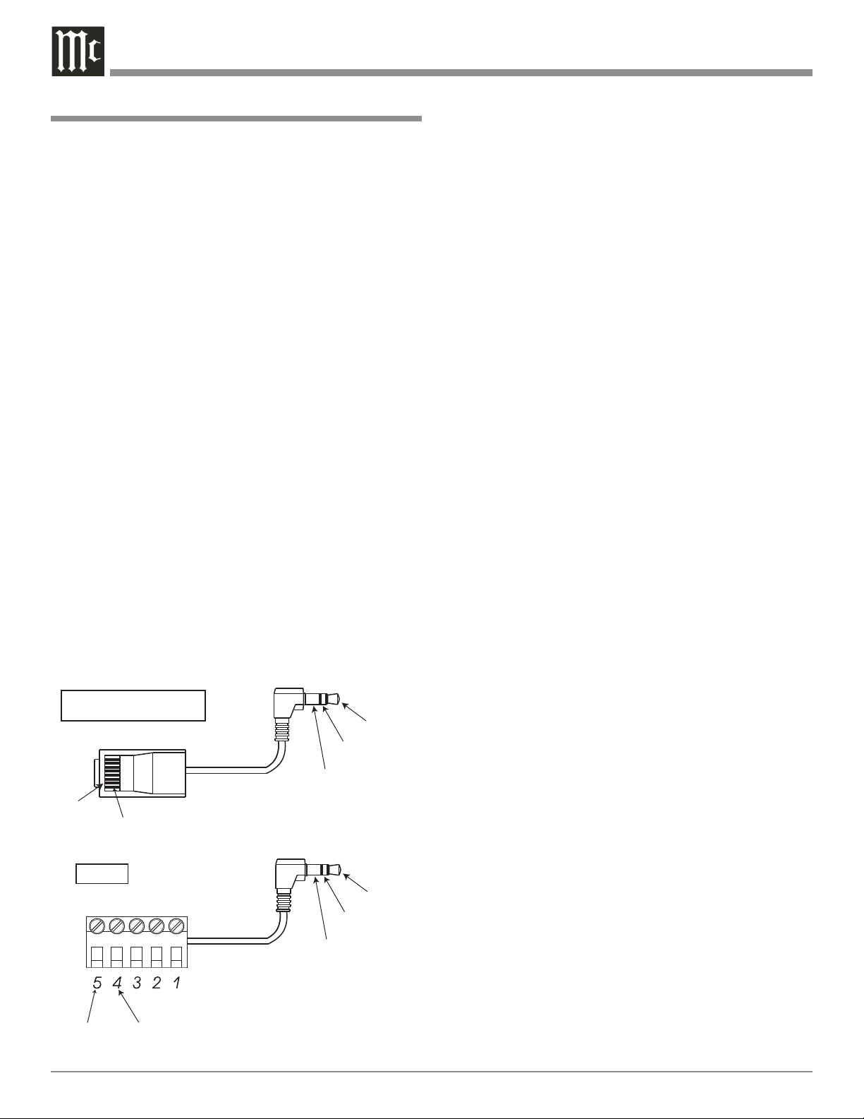
Data Signal
Data Ground
5 Pin Connector
Data
Signal
N/C
Data
Ground
Stereo
Mini
Plug
Data
Signal
N/C
Data
Ground
Data Signal
Pin1
Data
Ground
Pin 2
RJ45 Connector
Stereo
Mini
Plug
4
1. The Main AC Power going to the VP1000 and any other
McIntosh Component(s) should not be applied until all
the system components are connected together. Failure
to do so could result in malfunctioning of some or all of
the system’s normal operations. When the VP1000 and
other McIntosh Components are in their Standby Power
Off Mode, the Microprocessor’s Circuitry inside each
component is active and communication is occurring
between them.
2. For additional connection information, refer to the
owner’s manual(s) for any component(s) connected to
the VP1000 Video Processor.
3. The McIntosh VP1000 is designed to be used with the
McIntosh AP1000 Processor. It also integrates with
the McIntosh MX Series A/V Control Centers including the MX136, MX135, MX134, MX132, MX120 or
MX119.
4. When the VP1000 (Zone A) is used with one of the McIntosh MX Series A/V Control Centers it is important
to connect the SUM A Data Port to the VP1000 DATA
A IN Jack.
5. The VP1000 (Zone B) Data B Port may also be connected to one of the McIntosh MX Series A/V Control
Centers Zone B Sum Data Stream via the Zone B Keypad connection. The MX132 uses a five pin plug and
the rest of the MX Series A/V Control Centers use a
RJ-45 Connector Plug. If there are already connections
made to the Zone B Keypad Connector a “Y” adapter
will also be needed. Refer to the appropriate figure
below for adapter pin connections.
MX136, MX135, MX134,
MX120 and MX119
MX132
Table of Contents and General Information
6. When the VP1000 is used with a McIntosh MX Series
A/V Control Center, the MX A/V Control Center Setup
On-Screen Menu can viewed by connecting the Zone A
Composite Video Output to one of the VP1000 Composite Inputs.
7. The IR Inputs (Zone A and Zone B), with 1/8 inch mini
phone jacks, are configured for non-McIntosh IR sensors such as a Xantech Model 291-80. To avoid possible
interaction, disable the VP1000 Front Panel Sensor
with the switch recessed in an opening on the bottom
cover near the Front Panel, left side.
8. The VP1000 On-Screen Menu is designed to be viewed
primarily on a HD (High Definition) TV/Monitor
with a minimum resolution of 720p (1280x720). When
viewed on a SD (Standard Definition) TV/Monitor with
a resolution of 480i (720x480) the sides of the menu
may not be visible. This occurs due to the NTSC Overscan Standard.
9. The VP1000 is designed to accept video signals with
resolutions up to 1920x1080i at 60Hz. It will accept
a 1920x1080p input signal for processing and may be
selected for either Zone A or Zone B HDMI Monitor
Output (but not both simultaneously).
10. The VP1000 is in compliance with industry standards
for protection of copyrighted video/audio materials,
DRM (Digital Rights Management). The protection
is known as HDCP (High-Bandwidth Digital Content
Protection). When the VP1000 receives a digital signal
containing the HDCP digital f lag, via an HDMI Input
(HD1-HD4), the signal may only be viewed on a TV/
Monitor with HDCP compliant circuitry built-in and is
connected to a VP1000 HDMI Output connector. The
VP1000 Component Video Ouputs, S-Video Outputs
and Composite Video Outputs will have no output signal when the source selected contains a HDCP digital
flag.
11. The Composite Video and S-Video Monitor A/B Output Jacks are active only when the resolution of the
VP1000 is set to 720x480i.
12. The VP1000 Monitor A Output Jacks can provide
either a YPbPr or RGB Video Signal selected by the
Front Panel RGB/COMP Push-button.
13. Availability of the VP1000 video processing options are
dependent on the type of video output and the resolution settings.
14. When the VP1000 Video Processor is first connected to
AC Power, it will go through an initialization process
and various messages will appear on the Front Panel
Information Display. After the word “READY” ap-
Power
Control
Ground
N/C
Data
Signal
N/C
Data
Ground
HDMI Type A
Connector
PIN 1
PIN 19
PIN 2
PIN 18
IR Data
Control
Ground
N/C
General Information, Connectors and Cable Information
General Information, con’t
pears, the VP1000 will go into the Standby Mode and
is now ready to switch On.
15. When the symbol illustrated here is located on the
product or on the packaging, it indicates
the product must not be disposed of with
your other household waste. Instead, it
is your responsibility to dispose of your
waste equipment by handing it over to
a designated collection point for the
recycling of waste electrical and electronic equipment. The separate collection and recycling
of your waste equipment at the time of disposal will
help to conserve natural resources and ensure that it is
recycled in a manner that protects human health and
the environment. For more information about where
you can drop off your waste equipment for recycling,
please contact your local city office, your household
waste disposal service or the McIntosh Dealer where
you purchased the product.
Connector and Cable Information
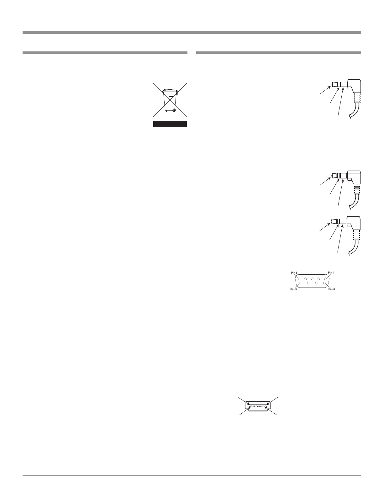
Power Control Connectors
The VP1000 Power Control Output Jacks send and Power
Control Input Jacks receive Power On/Off Signals when
connected to McIntosh and other
Components. A 1/8 inch stereo mini
phone plug is used for connection to
the Power Control Input and Outputs
on the VP1000.
Note: The Data and Power Control Connecting Cable is avail-
able from the McIntosh Parts Department:
Data and Power Control Cable Part No. 170-202
Six foot, shielded 2 conductor, with 1/8 inch stereo mini
phone plugs on each end.
Data Port Connectors
The VP1000 Data In Ports receives
Remote Control Signals from McIntosh Components. A 1/8 inch stereo
mini phone plug is used for connection. The IR Ports also use a 1/8
inch stereo mini phone plug and
allow the connection of other brand
IR Receivers to the VP1000.
RS232 DB9 Connector Pin Layout
1. N/C 6. N/C
2. Data Out (TXD) 7. N/C
3. Data In (RXD) 8. N/C
4. N/C 9. N/C
5. Gnd.
HDMI Type A Connector
1. TMDS Data2+ 8. TMDS Data0 Shield 15. SCL
2. TMDS Data2 Shield 9. TMDS Data0- 16. SDA
3. TMDS Data2- 10. TMDS Clock+ 17. DDC/
4. TMDS Data1+ 11. TMDS Clock Shield CEC
5. TMDS Data1 Shield 12. TMDS Clock- Ground
6. TMDS Data1- 13. CEC 18. +5V
7. TMDS Data0+ 14. Reserved 19. Hot
Plug
Detect
5

Introduction
The McIntosh VP1000 Video Processor is one of the finest
video scalers, video signal enhancers and video switchers
ever created. The two zone video processor provides con
nections for various video input sources and output formats
to monitors located in different rooms. The life like images
produced by the VP1000 are like being there in person.
Performance Features
• Dual Zone with Multi-Monitor Connectivity
The VP1000 is two complete and independent Digital Video Signal Processors in one component. Up to four monitors may be connected per Zone, with outputs including
HDMI, DVI-D
ite Video. This allows for extreme f lexibility in any home
environment. Both Zones could even be in the same room,
providing a correctly scaled digital signal going to a front
projector with a large screen and at the same time another
scaled digital signal going to a smaller wall mounted f lat
screen monitor.
• Spatial Iteration
Input Signals of 480i (interlaced) or 1080i scan lines of
video are first converted to 1080p (progressive) scan lines
of video, using the latest in scaling algorithms. The 1080p
signal is then analyzed using the processing of twelve dif
ferent points spatially and three points temporally in the
visual information. All of this special processing delivers
the utmost in video clarity and image resolution.
• Digital Scaling with Dynamic Stretch Enhancement
All incoming Video Signals, both Analog and Digital, are
scaled to match the aspect ratio and the native resolution
of the display monitors connected to both Zone A and B,
with no video processing artifacts. The Dynamic Stretch
Enhancement Circuitry completely fills the display moni
tor screen regardless of the aspect ratio and resolution of
the video source. There are user adjustments providing
flexibility in determining the best image stretch without
the side effects typically produced by the simple stretch
processing built-in to most display monitors.
• Digital Picture and Edge Enhancement
An advanced algorithm allows adjustment of the gray scale
values in both the light and dark areas of the video signal
producing a more realistic image with greater depth. Most
consumer products allow only adjustments to gray scale
values in the light areas of the image. The unique edge
enhancement circuitry provides a sharper image, result
1
, Component Video, S-Video and Compos-
-
-
-
ing in a viewing experience far superior to conventional
sharpness controls. This is accomplished by processing the
video signal in both the horizontal and vertical directions.
The results are smooth, vibrant, color-saturated images
that are truly film-like in quality.
• High Bandwidth Circuitry
The VP1000 is able to deliver the highest-quality video
images by utilizing ultra-linear components with an ex
tremely wide bandwidth in excess of 300 MHz, which is
over three-times the bandwidth commonly used for HDTV
products. The Digital Video Internal Clock Exchange
circuitry regenerates the high frequency digital processing
clock from the incoming digital video signal thus providing superior performance when converting an incoming
1080i signal to 1080p scan output signal. This regeneration
maximizes the video performance for displaying signals
in true HDTV 1080p. There are seven individual settings
allowing adjustment of the digital processing clock phase
with respect to the video signal thus assuring the absolute
best picture quality.
• High Definition PIP Modes
The VP1000 is one of the first Video Processors to allow
two different video sources, both with High Definition
signals, to be viewed in either Picture-In Picture or Pic
-
ture-By-Picture Modes.
• Automatic Synchronization Regeneration
The VP1000 automatically corrects for the unstable syn
chronization signals that are part of an analog video signal
from sources such as VCR and Laser Disc players. The circuitry performing this correction is know as a Time Base
Corrector (TBC) and is normally only found in professional broadcast equipment. By first processing the analog
signal with the TBC, the best possible results are achieved
with the Digital Scaling and the other Video Enhancement
Circuitry.
• Enhanced HDMI Connectivity
The VP1000 HDMI (High-Definition Multimedia In
terface) Circuitry goes beyond the typical HDMI implementation found in other products. Source components
connected to the VP1000 using the HDMI connections
are requested to provide the Highest Resolution Digital
Video and Audio Signals independent of the capability
of components connected to the VP1000 HDMI Outputs.
1
Using optional HDMI to DVI-D adapter available from your dealer
6

Introduction and VP1000 Features
The HDMI Output Circuitry analyzes any possible signal
delays caused by the interconnect cable and will automatically compensate up to the maximum recommended cable
length.
• Information Displays
The Multifunction Front Panel Display indicates vari
ous information including Source Selection and Output
Resolution. The Menu Options and Adjustments are also
displayed On-Screen including Aspect Ratio and various
video settings. The Front Panel Display intensity is also
adjustable.
• Precision Technology
The VP1000 uses the latest in design technology includ
ing impedance matched multilayer surface mount circuitry
providing wideband, low-noise video processing.
• Remote Control and External Sensor Inputs
The Remote Control together with provisions to connect
external sensors, provides control of the VP1000 operating
functions.
• Fiber Optic Solid State Front Panel Illumination
The even Illumination of the Front Panel is accomplished
by the combination of custom designed Fiber Optic Light
Diffusers and extra long life Light Emitting Diodes
(LEDs). The glass Front Panel ensures the pristine beauty
of the VP1000 will be retained for many years.
• Total Component Integration
The VP1000 is designed to work seamless with the McIn
tosh AP1000 Audio Processor and the McIntosh MDLP1
Digital Video Projector. It also integrates with the McIntosh MX Series A/V Control Centers including the
MX136, MX135, MX134, MX132, MX120 or MX119.
• Data Ports and RS232
There are Data Input Ports to allow communication be
tween the VP1000 and other McIntosh components. An
RS232 Port also permits two way communication with
other components.
• Power Control Outputs
Power Control connections for convenient Turn-On of Mc
Intosh Components and Accessories is included.
• Special Power Supply
Fully regulated Power Supplies ensure stable noise free
operation even though the power line varies.
• Extruded Side Panels
The sides of the VP1000 are extruded aluminum panels
with a bead blast textured surface and a black anodized
finish.
-
-
7
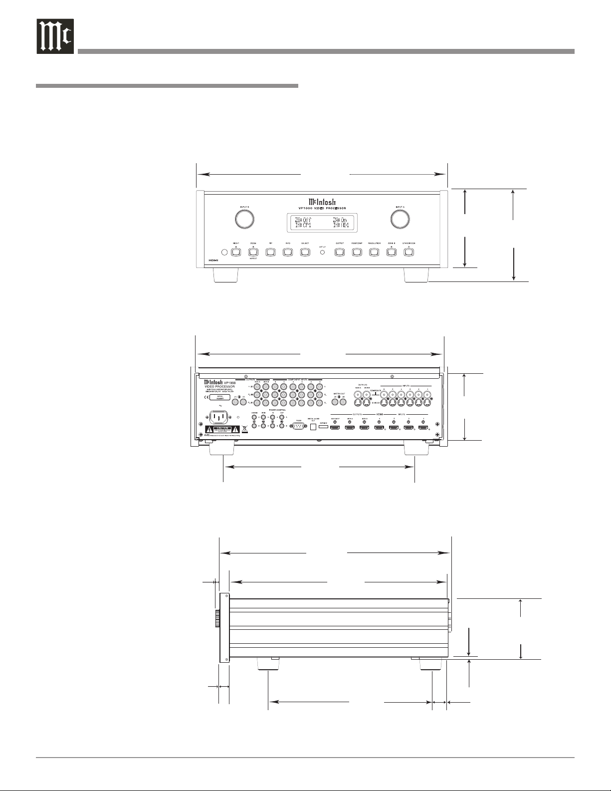
Dimensions
17-1/2"
44.45cm
4-5/8"
11.75cm
6"
15.24cm
17"
43.18cm
18-3/8"
46.67cm
3/16"
0.48cm
4-13/16"
12.22cm
14"
35.56cm
1-3/8"
3.49cm
13 -1/4"
33.65cm
17-1/16"
43.34cm
5/8"
1.59cm
Front View of the VP1000
Rear View of the VP1000
Side View of the VP1000
5-3/8"
13.69cm
13/16"
2.06cm
120V
50/60Hz 50 WATTS
The following dimensions can assist in determining the
best location for your VP1000. There is additional information on the next page pertaining to installing the VP1000
into cabinets.
Dimensions
8
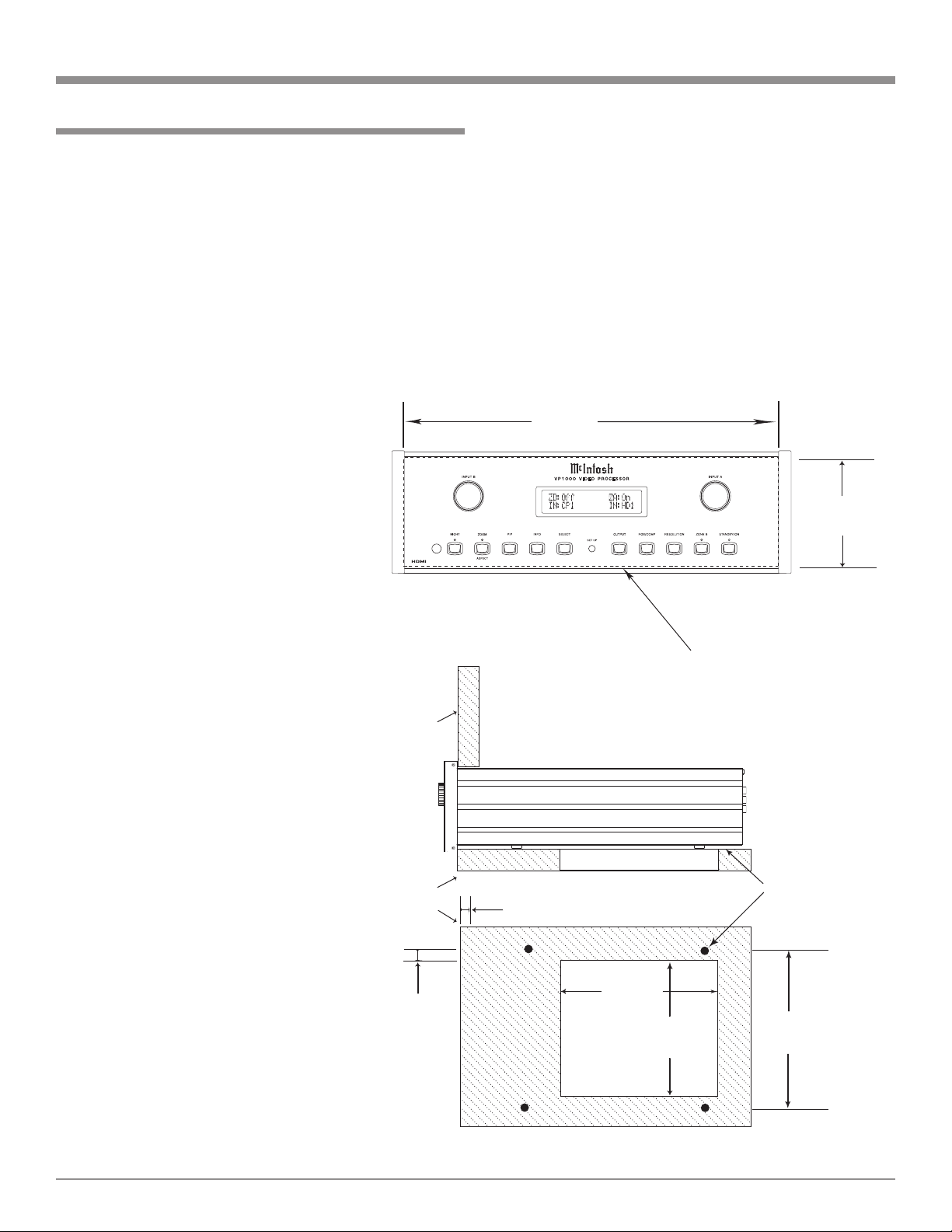
Installation
4 -7/8"
12.38cm
17-1/16"
43.34cm
Cutout Opening for Custom Mounting
VP1000 Front Panel
Custom Cabinet Cutout
14"
35.56cm
14"
35.56cm
15-1/16"
38.26cm
17/32"
1.35cm
Cutout Opening
for Ventilation
Cutout Opening for Ventilation
Support
Shelf
Cabinet
Front
Panel
Chassis
Spacers
VP1000 Side View
in Custom Cabinet
VP1000 Bottom View
in Custom Cabinet
1"
2.54cm
The VP1000 can be placed upright on a table or shelf,
standing on its four feet. It also can be custom installed in
a piece of furniture or cabinet of your choice. The four feet
may be removed from the bottom of the VP1000 when it is
custom installed as outlined below. The four feet together
with the mounting screws should be retained for possible
future use if the VP1000 is removed from the custom
installation and used free standing. The required panel
cutout, ventilation cutout and unit dimensions are shown.
Always provide adequate ventilation for your VP1000.
Cool operation ensures the longest possible operating life
for any electronic
instrument. Do
not install the
VP1000 directly
above a heat
generating component such as
a high powered
amplifier. If all
the components
are installed in
a single cabinet,
a quiet running
ventilation fan
can be a definite
asset in maintaining all the system
components at
the coolest possible operating
temperature.
A custom cabinet installation
should provide
the following
minimum spacing dimensions
for cool operation.
Installation
Allow at least 2 inches (5.08cm) above the top, 2 inches
(5.08cm) below the bottom and 1 inch (2.54cm) on each
side of the Video Processor, so that airflow is not obstructed. Allow 19-1/2 inches (49.53cm) depth behind the front
panel. Allow 1-1/8 inch (2.9cm) in front of the mounting
panel for knob clearance. Be sure to cut out a ventilation
hole in the mounting shelf according to the dimensions in
the drawing.
9
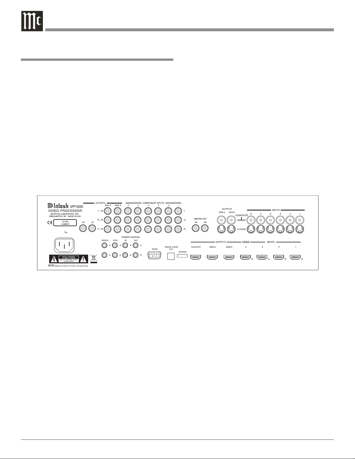
Rear Panel Connections
120V
50/60Hz 50 WATTS
The identification of Rear Panel Connections for the
VP1000 Video Processor is located on a separate folded
sheet contained in the Owner’s Manual Packet.
Refer to separate sheet “Mc1A” for the Rear Panel Connections
VP1000 Video Processor Rear Panel
Rear Panel Connections
10
 Loading...