

Page 1
AM/FM T uner Module
TM1
Dealer Installation Guide
McIntosh Laboratory, Inc. 2 Chambers S treet Binghamton, New York 13903-2699 Phone: 607-723-3512 FAX: 607-724-0549
Page 2
Overview
Table of Contents
The McIntosh TM1 AM/FM Tuner Module adds AM/FM
Broadcast Reception to the MX119, MX134 or MX135
A/V Control Centers; the MHT Series A/V System Controllers, C45 Audio Control Center and other McIntosh Components. It also adds functionality of a second Tuner to the
MR85 AM/FM T uner. Follow the instructions in this guide
for installing the TM1 into the MX119, MX134, MX135,
MHT Series, C45, MR85 and other McIntosh Components.
The TM1 Tuner Module is not a user installable product. It
must be installed by the T echnical Professionals at your
McIntosh Dealer.
Please Take A Moment
The serial number, installation date and Dealer name are
important to you for possible insurance claim or future service. The spaces below have been provided for you to
record that information:
Serial Number:
Installation Date:
Dealer Name:
T echnical Assistance
If at any time you have questions about installing and/or
operating the TM1 AM/FM Tuner Module, contact McIntosh for technical assistance at:
McIntosh Laboratory, Inc.
2 Chambers Street
Binghamton, New York 13903
Phone: 607-723-1545
Fax: 607-772-3308
Customer Service
If it is determined that your McIntosh product is in need of
repair, you can return it to your Dealer. You can also return
it to the McIntosh Laboratory Service Department. For assistance on factory repair return procedure, contact the
McIntosh Service Department at:
McIntosh Laboratory, Inc.
2 Chambers Street
Binghamton, New York 13903
Phone: 607-723-3515
Fax: 607-723-1917
Overview ........................................................................... 2
Please T ake a Moment ...................................................... 2
T echnical Assistance and Customer Service ..................... 2
Important Information....................................................... 2
T able of Contents .............................................................. 2
Parts List........................................................................... 3
Connector Information ...................................................... 3
MX119, MX134 or MX135 Installation Instructions....... 4
MHT Series Installation Instructions ................................ 6
C45 Installation Instructions ............................................. 8
MR85 Installation Instructions ....................................... 10
Important Information
1. Caution: To prevent the risk of electric
shock, first remove the AC Power Cord
from the back of the MX119, MX134,
MX135, MHT Series, C45, MR85 or
other McIntosh Component before
removing the top cover.
2. Some of the semiconductor devices (CMOS
and NMOS) used in the TM1 Module,
MX119, MX134, MX135, MHT Series, C45,
MR85 and other McIntosh Components are
inherently sensitive to static electricity even
when connected in a circuit, and can be permanently
damaged by a static electricity discharge. When handling
the TM1 and working inside the MX119, MX134, MX135,
MHT Series, C45, MR85 or other McIntosh Components,
follow the procedures below to insure against static
electricity damage.
A. Make sure the MX119, MX134, MX135, MHT Series,
C45, MR85 or other McIntosh Components are
properly grounded.
B. Use an approved wrist strap that is grounded.
C. Remove the TM1 from the Anti-Static Bag and work
with it only after the above conditions have been met.
D. The RAA1 Remote AM Antenna contains the Tuned
AM RF Amplifier First Stage Circuitry and is
matched to the specific AM/FM Tuner Module.
3. Some of the Installation Instructions in this Dealer
Installation Guide are also used for other McIntosh
Components. To identify the appropriate Installation
Instructions, refer to the label located on the Connector
Cover metal plate inside the McIntosh Component.
During the installation process this cover is removed,
allowing for the AM and FM Antenna Connections.
Copyright 2005 © by McIntosh Laboratory, Inc.
2
Page 3
Parts List and Connector Information
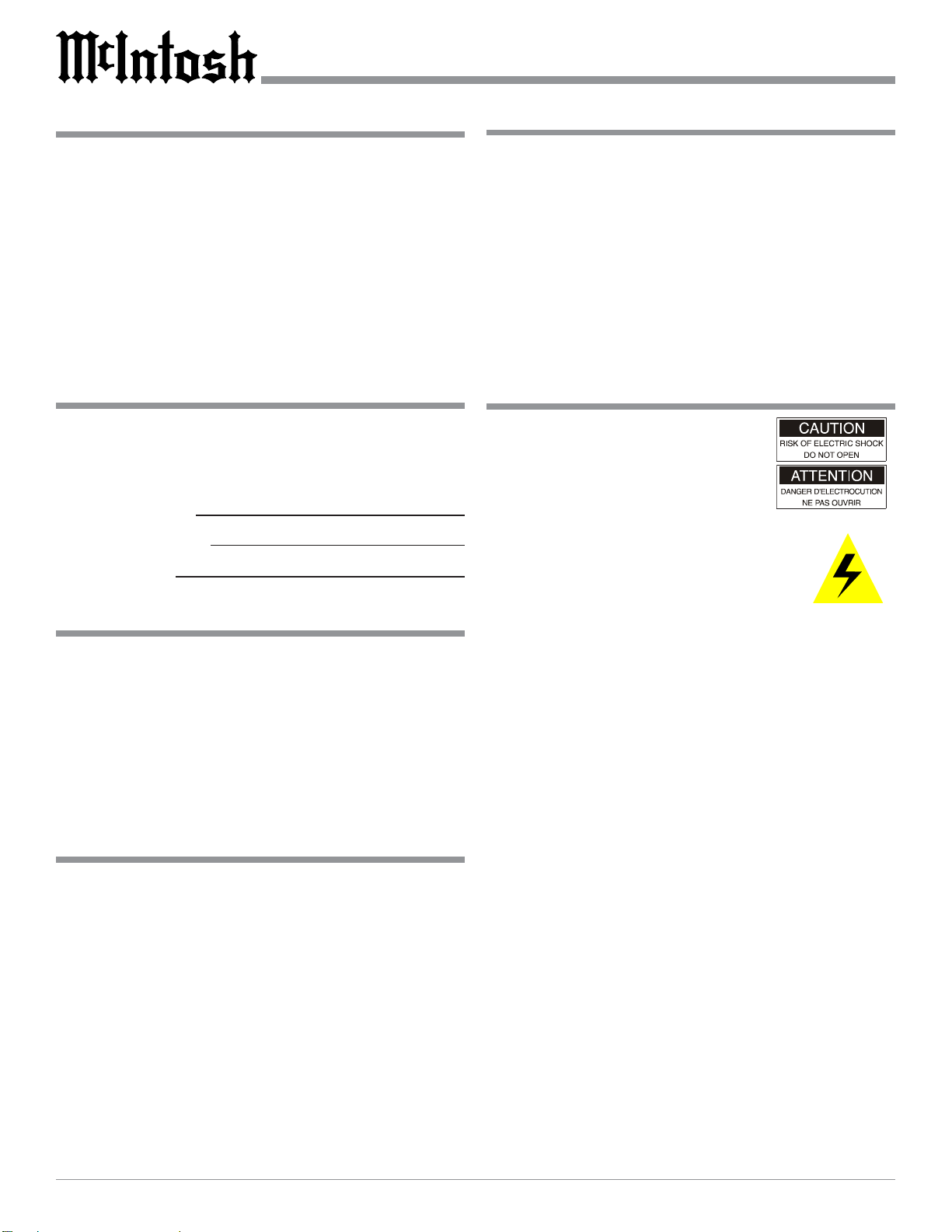
Parts List
Part Number Description Figure Number
049084 AM/FM Tuner Module 1
034134 Anti-Static Bag 1
049192 RAA1 Remote AM Antenna 2
049443 RAA1 Connection Cable Complete 2
171404 Seven conductor ribbon cable 1
171405 Six conductor ribbon cable 1
171406 Four conductor ribbon cable 1
TM1 Serial Number Label 1
AM/FM Tuner Module
T uner Module
Connecting
Cables
TM1 Serial Number Label
Anti-Static Bag
Connector Information
RAA1 Connectors
Connect the shield and two leads of a shielded 2 conductor
cable to the supplied 5 Pin T erminal Connector Plug. Refer
to the connection information on the top cover of the RAA1.
If there is need to make-up a longer cable, use a two conductor shielded wire and the connectors below .
5 PinT erminal Connector
1. N/C
2. N/C
3. Red W iire
15
4. Black Wire
5. Green Wire (Shield)
7 Pin DIN Connector
1. Red W ire
2. Black Wire
3. N/C
4. N/C
5. N/C
6. Jumper from Pin 7
7. Green Wire (Shield) and Jumper to Pin 6
Red
Black
Green
Figure 1
RAA1 Remote AM Antenna
RAA1 Connection Cable
Figure 2
3
Page 4
MX119, MX134 or MX135
Removing Covers
1. Remove ALL connecting cables from the Rear Panel of
the MX119, MX134 or MX135
Cover Screws
A/V Controller .
2. Remove two screws from each
side and two screws from the
back that secure the Top Cover to
the MX119, MX134 or MX135.
3. Lift off the Top Cover by grasping the rear sides of the top cover
and lifting up and away from the
MX119, MX134 or MX135.
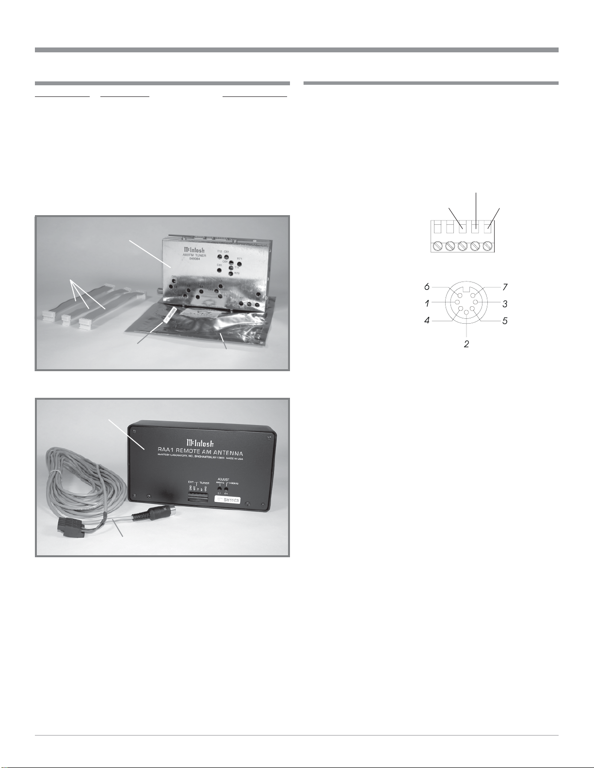
4. Remove the Inside Connector
Cover which is secured with two
Phillips Head Screws and is located on the Rear Panel. Refer to
Figure 3
figures 3 and 4.
Note: Retain the two screws as they will be used later to
install the AM/FM Tuner Module.
Installing the Cables and
Module
5. Locate the three supplied
Rear Panel
Inside Cover
ribbon cables from the
shipping carton and attach the plug of the Six
Conductor Ribbon Cable
to the six pin Socket “J3”
as indicated on the
MX119, MX134 or
Data PC Board
MX135 Data PC Board.
Refer to figure 1 on page
3 and figure 4 on this
Connections
for Ribbon
Cables
page.
Note: The six pin Cable
Plug and PC Board
Socket are “keyed”
to attach only in one
direction, do not
force it on
backward.
6. In a similar fashion, attach the plug of the Four
Figure 4
J3
J2
J1
Conductor Ribbon Cable to the four pin PC Board
Socket “J2” and the plug of the Seven Conductor Ribbon Cable to the seven pin Socket “J1”.
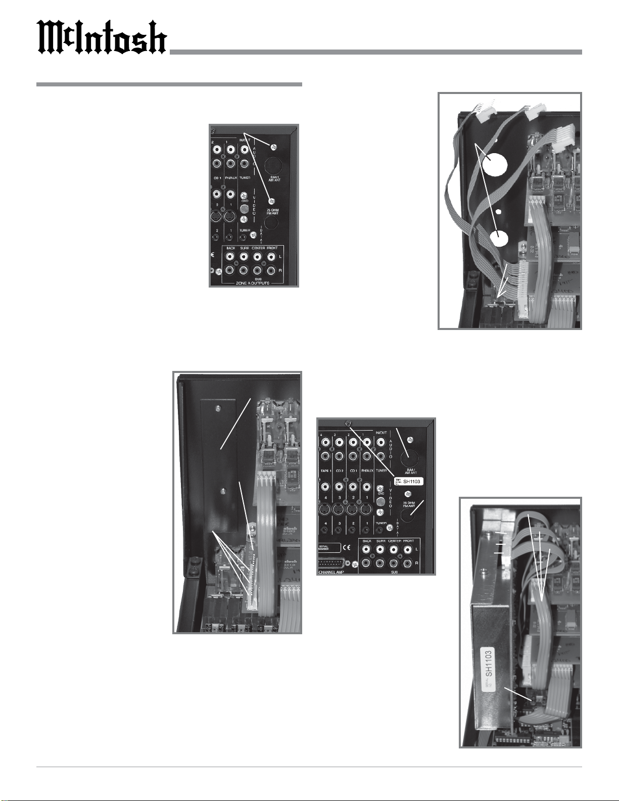
7. Relocate the free ends of the previously installed cables
and rotate them over the top and to the right of the attached cable ends. Refer to figure 5.
8. Locate the AM/FM Tuner Module in the anti-static bag.
There is a TM1 Serial
Number Label attached to the outside
of the bag. Refer to
Rear Panel
Openings
Rear Panel
Inside Cover
figure 1. Remove the
label from the bag and
attached it to the Rear
Panel of the MX119,
MX134 or MX135
below the chassis
opening labeled
RAA1 AM ANT
(DIN Connector). Refer to figure 6.
9. Remove the AM/FM
Tuner Module from
the anti-static bag.
Refer to figure 1.
10. Orient the Module so
the “F” Connector, that is at the bottom of the Module,
will fit through the lower opening of the MX119,
Rear Panel
Cover Screws
Cables
Connected
to PC Board
Figure 5
MX134 or MX135 Rear Panel (the cover was previously removed in Step 4) and the three PC Board Connectors are facing up. Refer to figures 5 and 6.
TM1 Label
DIN Connector
11. Secure the Module to the
MX119, MX134 or
MX135 Rear Panel with
“F”
C
o
n
n
e
c
t
o
r
Figure 6
rear panel in Step 4.
12. Attach the plug of the
Six Conductor Ribbon
the two Phillips Head
Screws that were previously removed from the
J4
J5
J3
Cables
from Data
PC Board
Cable coming from the
six pin Socket “J3” (as
indicated on the
MX119, MX134 or
MX135 Data PC
Board) to the six pin
AM/FM
Tuner
Module
Socket (J4) of the Module, which is located
Figure 7
4
Page 5

closest to the MX119, MX134 or MX135 Rear Panel.
Refer to figure 7.
Note: The six pin Cable Plug and PC Board Socket are
“keyed” to attach only in one direction, do not
force it on backward.
13. In a similar fashion, attach the plug of the Four Conductor Ribbon Cable coming from the four pin Socket
“J2” (as indicated on the MX119, MX134 or MX135
Data PC Board) to the four pin Socket (J5) of the Module, which is the middle one of the three in-line connectors.
14. Also attach the remaining plug of the Seven Conductor
Ribbon Cable coming from the seven pin Socket “J1”
(as indicated on the MX119, MX134 or MX135 Data
PC Board) to the seven pin Socket (J4) of the Module,
which is located closest to the MX119, MX134 or
MX135 Front Panel.
Reinstalling Cover and Setup
In the following steps the MX119, MX134 or MX135
SETUP feature will be accessed to select the country of operation for proper AM and FM reception. The SETUP
Mode is On-Screen V ideo based menu and it will be required to connect the MX119, MX134 or MX135 MONITOR A Video Output (S-Video or Composite) to a TV/
Monitor. Refer to figures 8 through 13.
15. Reinstall the MX119, MX134 or MX135 Top Cover
(refer to Steps 2 and 3 on page 3).
16. Reconnect the hookup Connecting Cables to the Rear
Panel of the MX119, MX134 or MX135.
17. Place the MX119, MX134 or MX135 Main POWER
Switch to the ON position and press the STANDBY/
ON Push-button.
Note: Refer to the MX119, MX134 or MX135 Owner ’s
Manual for additional Operational Details.
MX119, MX134 or MX135 Installation Instructions
Figure 9
Figure 10
Figure 11
Figure 12
ADJUSTMENTS HAVE BEEN MADE
DO YOU WANT TO SAVE THEM?
NO
YES
Figure 8
18. Press the SETUP Push-button to enter the Setup Mode.
19. Press and release both TUNING Up and Down Pushbuttons and “NO TUNER” will appear on the Front
Panel Alphanumeric Display. Refer to figure 9.
20. Press and release both TUNING Up and Down Pushbuttons until “USA” appears on the Front Panel Alphanumeric Display . Refer to figure 10.
Note: If this MX119, MX134 or MX135 is being operated
in a country other than the USA, select the
appropriate country group. Refer to figures 11 and
12.
Figure 13
21. Select EXIT from the Main System Setup Menu and
select YES to save the Changes. Refer to figure 13.
22. Verify the AM and FM Tuner is functioning properly.
5
Page 6

MHT Series Component
Removing Covers
1. Remove ALL connecting cables from the Rear Panel of
the MHT Series A/V System Controller.
2. Remove two screws from each
side and two screws from the back
Cover
Screws
that secure the Top Cover to the
MHT Series Component.
3. Lift off the Top Cover by grasping the rear sides of the top cover
and lifting up and away from the
MHT Series Component.
4. Remove the Inside Connector
Cover which is secured with two
Figure 10
Phillips Head Screws and is located on the Rear Panel.
Refer to figures 10 and 11.
Note: Retain the two screws as they will be used later to
install the AM/FM Tuner Module.
Installing the Cables and Module
5. Locate the three supplied ribbon cables from the shipping
carton and attach the plug of
the Six Conductor Ribbon
Cable to the six pin “J3” as
indicated on the MHT Series
Component Main Audio PC
Rear
Panel
Inside
Cover
Board. Refer to figures 1 (on
page 3) and 12.
Note: The six pin Cable Plug
and PC Board Socket are
“keyed” to attach only in
one direction, do not force
it on backward.
Figure 11
6. In a similar fashion, attach the plug of the Four Conductor Ribbon Cable to the four pin PC Board Socket
“J2” and the plug of the Seven Conductor Ribbon Cable
to the seven pin PC Board Socket “J1”.
7. Relocate
the free
ends of
the previously
installed
cables so
that they
Rear
Panel
Openings
Connections
for Ribbon
Cables
will not
interfere
with the
installa-
Main Audio
PC Board
Figure 12
tion of the AM/FM Tuner Module. Refer to figure 13.
8. Locate
the AM/
FM
Tuner
Module
in the
anti-
Cables
Connected
to PC Board
static
bag.
There is
AM/FM
T uner
Module
a TM1
Serial
Number
Label
attached
Figure 13
to the outside of the bag. Refer to figure 1 on page 3.
Remove the label from the bag and attached it to the
Rear Panel of the MHT Series Component below the
opening labeled RAA1 AM ANT (DIN Connector). Refer to figure 14.
9. Remove the AM/FM T uner Module from the anti-static
bag. Refer to figure 1 on page 3.
10. Orient the Module so the “F” Connector, that is at the
bottom of the Module, will fit
through the lower opening of
the MHT Series Component
Rear Panel (the cover was previously removed in Step 4) and
the three PC Board Connectors
DIN
Connector
are facing up. Refer to figures
13 and 14.
TM1 Label
11. Secure the Module to the MHT
Series Component Rear Panel
with the two Phillips Head
Screws that were previously
“F”
Connector
removed from the rear panel in
Step 4.
12. Attach the plug of the Six Con-
J3
J2
J1
ductor Ribbon Cable coming from the six pin Socket
“J3” (as indicated on the MHT Series Component Main
Audio PC Board) to the six pin PC Board Socket (J3)
of the Module, which is located closest to the MHT Series Component Rear Panel. Refer to figure 13.
Note: The six pin Cable Plug and PC Board Socket are
“keyed” to attach only in one direction, do not
force it on backward.
13. In a similar fashion, attach the plug of the Four Conductor Ribbon Cable coming from the four pin Socket
“J2” (as indicated on the MHT Series Component Main
Figure 14
6
Page 7

MHT Series Component Installation Instructions
Audio PC Board)
to the four pin PC
Board Socket (J5)
of the Module,
J4
which is the middle
one of the three inline connectors.
J5
J3
14. Also attach the remaining plug of the
Seven Conductor
Ribbon Cable
coming from the
seven pin Socket
“J1” (as indicated
AM/FM
T uner
Module
Figure 15
Cables from
Main Audio
PC Board
on the MHT Series
Main Component Audio PC Board) to the seven pin PC
Board Socket (J4) of the Module, which is located closest to the MHT Series Component Front Panel.
Reinstalling Cover and Setup
In the following steps the MHT Series Component SETUP
feature will be accessed to select the country of operation
for proper AM and FM reception. The SETUP Mode is OnScreen V ideo based menu and can be viewed by connecting
the MHT Series Component MONITOR A Video Output
(S-V ideo or Composite) to a TV/Monitor. This will allow
for verifying the Tuner Country setting.
15. Reinstall the MHT Series Component Top Cover (refer
to Steps 2 and 3 on page 5).
16. Secure the MHT Series Component Top Cover to the
Rear Panel with the two screws that were previously
removed.
17. Reinstall the four screws to the sides of the MHT Series
Component A/V System Controller.
18. Reconnect the hookup Connecting Cables to the Rear
Panel of the MHT Series.
19. Place the MHT Series Main POWER Switch to the ON
position and press the ST ANDBY/ON Push-button. Refer to figure 16.
Note: Refer to the MHT
Series Component
Owner’s Manual for
additional
Operational
Details.
The MHT Series Component
Default Operational Setting
for the TM1 AM/FM Tuner
Module is “USA”. T o check
the current setting perform the
Figure 16
following:
20. Press and hold the front panel Setup Push-button approximately three seconds to enter the Setup Mode. The
word SETUP will appear on the MHT Series Component Front Panel Display and the MAIN SYSTEM
SETUP Menu will appear on the Monitor/TV screen.
21. Using the UpS or DownT directional push-buttons
select SYSTEM SETTINGS on the On-Screen Menu,
followed by the SELECT Push-button on the Remote
Control. The On-Screen Menu Item TUNER indicates
the current country setting of the TM1 AM/FM Tuner
Module. If it needs to be changed to a different country
group perform step 22, if not go to step 23. Refer to figure 17.
MENU: SYSTEM SETUP
`1. VIDEO NTSC
2. TUNER USA
3. TEMP DISPLAY Full
4. OSD ROUTING Both
5. VIDEO FORMAT Auto
EXIT
Figure 17
Note: The some MHT Series Components have
additional menu items (e.g. OSD ROUTING and
VIDEO FORMAT) that will not appear on other
MHT Series Component On-Screen Menu.
22. With the MHT Series Component in the S tandby Mode,
press the ST ANDBY/ON Push-button followed by immediately pressing and holding in the appropriate Front
Panel Push-button.
Push-button Country Group
TRIM DownT USA
TRIM UpS EUROPE
LATE NIGHT JAPAN
Note: The Front Panel Alphanumeric Display will
indicate the specific MHT Series Component model
number followed by “TUNER USA” or “TUNER
EUROPE” or “TUNER JAPAN”.
23. Verify the AM and FM Tuner is functioning properly.
7
Page 8

C45
Removing Covers
1. Remove ALL connecting cables
from the Rear Panel of the C45
Audio Control Center.
2. Remove two screws from each
side and two screws from the back
that secure the Top Cover to the
C45.
3. Lift off the Top Cover by grasping the rear sides of the top cover
and lifting up and away from the
C45.
4. Remove the Inside Connector
Cover which is secured with two
Phillips Head Screws and is located on the Rear Panel. Refer to
figures 18, 19 and 20.
Note: Retain the two screws as they
will be used later to install
the AM/FM Tuner Module.
Installing the Cables and Module
5. Locate the three supplied ribbon cables from the shipping carton and attach the plug of the Six Conductor
Ribbon Cable to the six pin Socket “J23” as indicated
on the C45 Main PC
Board. Refer to figure 1
on page 3, figures 20 and
21 on this page.
Note: The six pin Cable
Plug and PC Board
Socket are “keyed”
to attach only in one
direction, do not
force it on backward.
6. In a similar fashion, attach the plug of the Four
Conductor Ribbon Cable
to the four pin PC Board
Socket “J22” and the plug
of the Seven Conductor
Ribbon Cable to the seven pin Socket “J21”.
7. Relocate the free ends of the previously installed cables
and rotate them over the top and to the right of the attached cable ends. Refer to figure 21.
8. Locate the AM/FM Tuner Module in the anti-static bag.
There is a TM1 Serial Number Label attached to the
outside of the bag. Refer to figure 1 on page 3. Remove
the label from the bag and attached it to the Rear Panel
of the C45 below the opening labeled RAA1 AM ANT
(DIN Connector). Refer to figure 22.
Cover Screws
Figure 18
Rear Panel
Inside
Figure 19
9. Remove the AM/FM T uner Module from the anti-static
bag. Refer to figure 1 on page 3.
10. Orient the Module
so the “F” Connec-
Rear Panel Openings
tor, that is at the
bottom of the Module, will fit through
the lower opening
of the C45 Rear
Panel (the cover
was previously removed in Step 4)
and the three PC
Board Connectors
are facing up. Refer
Connections
for Ribbon
Cables
J23
J22
to figures 21 and
22.
J21
11. Secure the Module
to the C45 Rear
Figure 20
Panel with the two Phillips Head Screws that were previously removed from the rear panel in Step 4.
12. Attach the plug of the Six Conductor Ribbon Cable
coming from the six pin Socket “J23” (as indicated on
the C45 Main PC Board) to the six pin Socket of the
Module, which is located closest to the C45 Rear Panel.
Refer to figure 23.
Note: The six pin Cable Plug and PC Board Socket are
“keyed” to attach only in one direction, do not force it
on backward.
13. In a similar fashion, attach the plug of the Four Conductor Ribbon Cable coming from the four pin Socket
“J22” (as indicated on the C45 Data PC Board) to the
Cables
Connected
to Main PC
Board
J23
J22
J21
Figure 21
8
Page 9

C45 Installation Instructions
four pin Socket of the Module,
which is the middle one of the
three in-line connectors.
14. Also attach the remaining plug of
the Seven Conductor Ribbon
Cable coming from the seven pin
Socket “J21” (as indicated on the
C45 Data PC Board) to the seven
pin Socket of the Module, which
is located closest to the C45 Front
Panel.
Reinstalling Cover and Setup
In the following steps the C45 SETUP
feature will be accessed to select the
country of operation for proper AM
and FM reception. The SETUP Mode
is indicated on the
Front Panel Alphanumeric Display .
Refer to figures 24,
25 and 26.
J3
J5
J4
15. Reinstall the
C45 T op Cover
(refer to Steps
2 and 3 on
page 3).
16. Reconnect the
hookup Connecting Cables
to the Rear
Panel of the
C45.
17. Place the C45
Main POWER
Switch to the
Figure 23
ON position
and press the STANDBY/ON Push-button.
DIN Connector
“F”Connector
Figure 22
J23
J22
J21
AM/FM
T uner
Module
TM1
Label
Cables
from
Main
PC
Board
Main
PC
Board
Note: Refer to the C45 Owner’s Manual for additional
Operational Details.
18. Press the SETUP Push-button to enter the Setup Mode.
19. Press the MENU (TONE BYPASS) Push-button and
the last selected Setup Mode will appear on the Front
Panel Alphanumeric Display. If necessary continue to
press the MENU Push-button until “VERSION _._
_” appears on the Display . The character on the far
right side of the Firmware Version Number display indicates which country the Tuner is setup for proper operation. Refer to figure 24.
Alphanumeric Display Country Group
VERSION _._ U USA
VERSION _._ J JAPAN
VERSION _._ E EUROPE
Note: If the character on the far right side of the display
is an “U” the Tuner is set for reception in the
USA.
If the Tuner is setup for the country it will be operated in
proceed to step 23, if not then perform the following steps
first:
20. Press the MENU Push-button until the Front Panel Alphanumeric Display indicates COUNTRY CODE. Refer to figure 25.
Figure 25
21. Press the TRIM LEVEL UPS or DOWNT Push-button to change the Country Group. Refer to figure 26.
Figure 26
22. Press the SETUP Push-button to exit the Setup Mode.
23. Verify the AM and FM Tuner is functioning properly.
Figure 24
9
Page 10

MR85
Removing Covers
1. Remove ALL connecting cables from the Rear Panel of
the MR85 AM/FM Tuner.
2. Remove two screws from each side
and two screws from the back that
secure the Top Cover to the MR85.
3. Lift off the Top Cover by grasping
the rear sides of the top cover and
lifting up and away from the MR85.
4. Remove the Inside Connector Cover
which is secured with two Phillips
Head Screws and is located on the
Rear Panel. Refer to figures 27 and
28.
Note: Retain the two screws as they will be used later to
install the AM/FM Tuner Module.
Installing the Cables and Module
5. Locate the three supplied ribbon cables from the shipping carton and attach the plug of
the Six Conductor Ribbon Cable to
the six pin PC Board Socket “J3” as
indicated on the MR85 Main PC
Board. Refer to figure 1 (on page 3)
and figures 29, 31.
Note: The six pin Cable Plug and PC
Board Socket are “keyed” to
attach only in one direction, do
not force it on backward.
6. In a similar fashion, attach the plug
of the Four Conductor Ribbon
Cable to the four
pin “J2” and the
plug of the Seven
Conductor Ribbon Cable to the
seven pin Socket
“J1”.
7. Relocate the free
ends of the previously installed
cables and rotate
them over the top
Connections
for Ribbon
Cables
and to the right
of the attached
cable ends.
Main Audio
PC Board
8. Locate the AM/
FM Tuner Module in the anti-static bag. There is a TM1 Serial Num-
Cover Screws
Figure 27
Rear
Panel
Inside
Figure 28
Rear Panel
Openings
Figure 29
J3
J2
J1
ber Label attached to the outside
of the bag. Refer to figure 1 on
page 3. Remove the label from
the bag and attached it to the
Rear Panel of the MR85 below
the opening labeled RAA1 AM
ANT (DIN Connector). Refer to
figure 30.
9. Remove the AM/FM T uner
Module from the anti-static bag.
Refer to figure 1 on page 3.
10. Orient the Module so the “F”
Connector, that is at the bottom
of the Module, will
fit through the lower
opening of the
MR85 Rear Panel
(the cover was previously removed in
Step 4) and the three
PC Board Connectors are facing up.
Refer to figures 29,
30 and 32.
11. Secure the Module to
the MR85 Rear
Panel with the two
Phillips Head
Screws that were
previously removed
from the rear panel
in Step 4.
12. Attach the plug of
the Six Conductor
Ribbon Cable coming from the six pin
Socket “J3” as indicated on the MR85
Main PC Board to
the six pin Socket
“J3” of the Module,
AM/FM
T uner
Module
which is located
closest to the MR85
Rear Panel. Refer
to figure 32 and 33.
Note: The six pin
Cable Plug and
PC Board Socket
are “keyed” to
attach only in one direction, do not force it on
backward.
TM1 Label
DIN
Connector
“F” Connector
Figure 30
Cables
Connected
to PC
Board
Figure 31
Figure 32
10
Page 11

MR85 Installation Instructions
13. In a similar fashion, attach the
J3
plug of the Four
Conductor Ribbon
Cable coming
from the six pin
PC Board Socket
“J2” (as indicated
on the MR85
AM/FM
T uner
Module
J5
J4
Cables from
Main Audio
PC Board
Main PC Board)
to the four pin
Socket “J5” of the
Module, which is
the middle one of
the three in-line
connectors.
14. Also attach the remaining plug of
the Seven Conduc-
Figure 33
tor Ribbon Cable coming from the seven pin PC Board
Socket “J1” (as indicated on the MR85 Main PC
Board) to the seven pin Socket “J4” of the Module,
which is located closest to the MR85 Front Panel.
18. Press and hold in the SPATIAL and MONO Push-buttons until the Front Panel Alphanumeric Display indicates “SETUP V_.__ _. The character on the far right
side of the Firmware Version Number display indicates
which country the T uner is setup for proper operation.
Refer to figure 34.
Alphanumeric Display Country Group
SETUP _._ U USA
SETUP _._ J JAPAN
SETUP _._ E EUROPE
Note: If the character on the far right side of the display
is an “U” the Tuner is set for reception in the
USA.
If the Tuner is setup for the country it will be operated in
proceed to step 23, if not then perform the following steps
first:
19. Rotate the PRESET Control until the Front Panel Alphanumeric Display indicates COUNTRY CODE. Refer to figure 35.
Figure 35
Reinstalling Cover and Operation Check
In the following steps the MR85 SETUP feature will be accessed to select the country of operation for proper AM and
FM reception. The SETUP Mode is indicated on the Front
Panel Alphanumeric Display. Refer to figures 34, 35
and 36.
15. Reinstall the MR85 Top Cover (refer to Steps 2 and 3
on page 10).
16. Reconnect the hookup Connecting Cables to the Rear
Panel of the MR85.
17. Place the MR85 Main POWER Switch to the ON position and press the ST ANDBY/ON Push-button.
Note: Refer to the MR85 Owner’s Manual for additional
Operational Details.
20. Press the ENTER Push-button repeatedly until the correct Country Group appears. Refer to figure 36.
Figure 36
21. Rotate the PRESET Control until the Front Panel Alphanumeric Display indicates EXIT .
22. Press the ENTER Push-button to save the changes.
23. Verify that AM and FM reception for “TUNER 2” is
functioning properly .
Figure 34
11
Page 12

McIntosh Laboratory, Inc.
2 Chambers Street
Binghamton, NY 13903
The continuous improvement of its products is the
policy of McIntosh Laboratory Incorporated who
reserve the right to improve design without notice.
Printed in the U.S.A.
McIntosh Part No. 04071604
 Loading...