

McIntosh MR-80 Owners manual
THE MclNTOSH MR 80 DIGITAL FM TUNER
Reading Time: 32 Minutes
Price: $2.00

VARIOUS REGULATORY AGENCIES REQUIRE THAT WE BRING THE FOLLOWING
INFORMATION TO YOUR ATTENTION. PLEASE READ IT CAREFULLY.
WARNING: TO PREVENT FIRE OR SHOCK
HAZARD, DO NOT EXPOSE THIS UNIT TO
RAIN OR MOISTURE.
The Mclntosh you have purchased is a Model
MR 80. It has a serial number located on the rear
panel of the chassis. Record that serial number
here:
Serial Number
The model, serial number and purchase date are
important to you for any future service. Record the
purchase date here:
Purchase date
Upon application, Mclntosh Laboratory provides a
Three-Year Service Contract. Your Mclntosh authorized service agency can expedite repairs when you
provide the Service Contract with the instrument for
repair. To assist, record your Service Contract
number here:
Service Contract Number

Your MR 80 Digital FM Tuner
can give you many years of
satisfactory performance. If you
have any questions, please contact:
CUSTOMER SERVICE
Mclntosh Laboratory Inc.
2 Chambers Street
Binghamton, New York 13903-9990
Phone: 607-723-3512
Take Advantage of 3 years
of Contract Service ...
Fill in the Application NOW.
Contents
SERVICE CONTRACT INFORMATION . . . 1
INSTALLATION ..2
HOW TO CONNECT AND
BACK PANEL INFORMATION...4
FRONT PANEL INFORMATION
AND USE OF CONTROLS. . .6
TOP PANEL INFORMATION
AND SECONDARY CONTROLS . . .8
PERFORMANCE LIMITS . . .9
PERFORMANCE CHARTS. -10
TECHNICAL DESCRIPTION. 14
BLOCK DIAGRAM..20
MclNTOSH THREE YEAR SERVICE CONTRACT
An application for A THREE YEAR SERVICE CONTRACT is included with this manual.
The terms of the contract are:
1. Mclntosh will provide all parts, materials
and labor needed to return the measured
performance of the instrument to the
original performance limits. The SERVICE CONTRACT does not cover any
shipping costs to and from the authorized service agency or the factory.
2. Any Mclntosh authorized service agency
will repair Mclntosh instruments at nor-
mal service rates. To receive service
under the terms of the SERVICE CONTRACT, the SERVICE CONTRACT CER-
TIFICATE must be presented when the
instrument is taken to the service agency.
3. Always have service done by a
Mclntosh authorized service agency. If
the instrument is modified or damaged
as a result of unauthorized repair, the
SERVICE CONTRACT will be cancelled.
Damage by improper use or mishandling is not covered by the SERVICE
CONTRACT.
4. The SERVICE CONTRACT is issued to
you as the original purchaser. To protect you from misrepresentation, this
contract cannot be transferred to a second owner.
5. To receive the SERVICE CONTRACT,
your purchase must be made from a
Mclntosh franchised dealer.
6. Your completely filled in application for
the SERVICE CONTRACT must be postmarked within 30 days of the date of
purchase of the instrument.
7. To receive the SERVICE CONTRACT, all
information on the application must be
filled in. The SERVICE CONTRACT will
be issued when the completely filled in
application is received by Mclntosh
Laboratory Incorporated in Binghamton,
New York.
8. Units in operation outside the United
States and Canada are not covered by
the Mclntosh Factory Service Contract,
irrespective of the place of purchase.
Nor are units acquired outside the
U.S.A. and Canada, the purchasers of
which should consult with their dealer
to ascertain what, if any, service contract or warranty may be available locally.
Copyright 1980 © by Mclntosh Laboratory Inc.
1

How to Connect and
Back Panel Information
Refer to page 5.
AUDIO OUTPUTS
Use the FIXED OUTPUT jacks on the rear panel to
feed program to a stereo control preamplifier or
other equipment which has its own volume control.
The front panel VOLUME control does not affect the
loudness of the tuner at the FIXED OUTPUT jacks.
The output level is a nominal 1 volt for 100% FM
modulation.
Use the VARIABLE OUTPUT jacks to connect to
equipment such as a power amplifier or a tape
recorder where control of the volume at the tuner is
desired. The output at the VARIABLE OUTPUT jacks
is a nominal 2.5 volts for 100% FM modulation.
There is no difference in the signal quality at either
pair of output jacks.
Both pairs of OUTPUT jacks may be used simultaneously. The output impedance at both outputs is
very low so that long audio cables can be used
without a loss of high frequencies due to cable
capacity.
RF INPUTS — ANTENNA CONNECTIONS
Two of four different antenna systems can be
used with your MR 80. 1) an outdoor FM antenna, 2)
an all channel (UHF-VHF-FM) antenna, 3) a cable input from your local cable company, or 4) the indoor
dipole supplied with the MR 80. A switch is provided
on the top level set panel to select between two of
the four systems mentioned.
An outdoor antenna is recommended for optimum
performance in all areas. In fringe areas, best results
will be obtained with a highly directional FM antenna used in connection with a rotator. Rotate the
antenna until the best reception is obtained. Connect a 300 ohm outdoor antenna to the 300W ANTENNA (red) terminals. Connect a 75 ohm antenna
and/or 75 ohm cable system to the coaxial antenna
jack.
A flexible folded dipole antenna supplied with
your MR 80 may be used in urban or in high signal
strength areas. The flexibility of the thin flat wire
assembly permits it to be placed under a rug. tacked
behind the stereo or placed in any other convenient
location. In some cases it may be necessary to position the antenna for best signal reception. This
should be done before it is permanently located.
Avoid locating this antenna next to other wires or
metal objects. This antenna may not prove effective
in houses having metal siding or metal clad insula-
tion.
The cable signal from a local cable company or a
second FM antenna with 75 ohms impedance may
be connected to the coaxial cable jack.
REMOTE SCAN
The REMOTE SCAN CONTROL SIGNAL jack is to
be connected to the cable push button assembly
supplied with the MR 80 for remote tuning. Plug the
cable into the CONTROL SIGNAL jack. Pressing the
push button at the end of the cable causes the MR
80 to scan to the next station. The mode of scan can
be selected by the STATION'S slide switch. In the
PRESET position every time the push button is
depressed the MR 80 will scan to the next preset station. In the ALL position depressing the button will
cause the MR 80 to scan to the next station.
If REMOTE tuning is not used, leave the jack free
of any connection.
SCOPE
The vertical and horizontal scope jacks are provided to connect to a maximum performance indicator or an oscilloscope for indication of FM
multipath and signal strength. Connect the vertical
jack to the vertical input of the indicator and the
horizontal jack to the horizontal input.
UNSWITCHED AC POWER OUTLET
This outlet may be used to power auxiliary equip-
ment such as an antenna rotator or a maximum performance indicator. Power is available whenever the
MR 80 is connected to a power source.
4
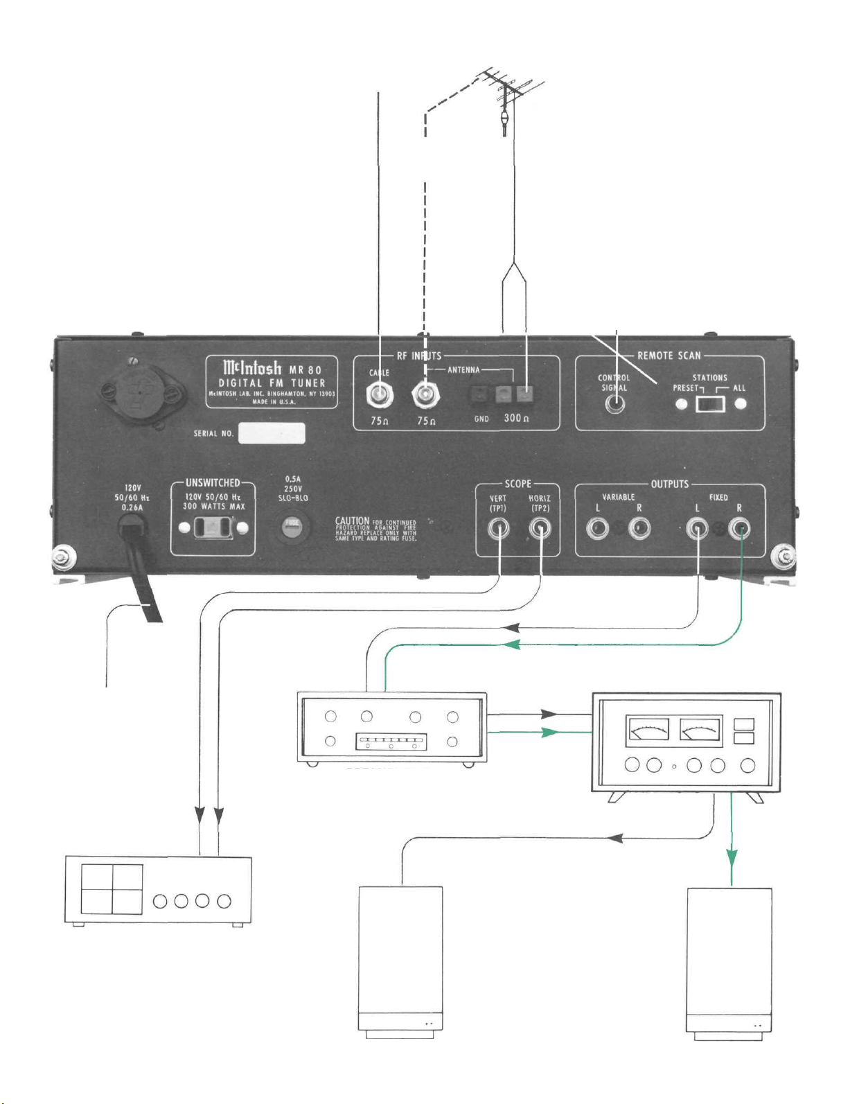
FM CABLE
INPUT OR
2ND 75W ANTENNA
LEAD-IN
OPTIONAL
75W
ANTENNA
LEAD-IN
FM ANTENNA
REMOTE CONTROL
PUSH BUTTON
TO AC
POWER
SOURCE
MAXIMUM PERFORMANCE
INDICATOR
OR
OSCILLOSCOPE
PREAMPLIFIER
LEFT SPEAKER
5
POWER AMPLIFIER
RIGHT SPEAKER

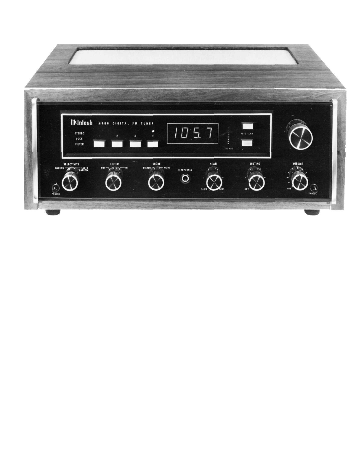
Front Panel Information and
Use of Controls
The MR 80 Tuner has the most flexible control
system ever designed in a stereo FM tuner. Correct
use of these controls will yield a higher level of performance than previously possible with conventional tuners.
VOLUME CONTROL AND AC POWER SWITCH
The VOLUME control has been precision tracked
throughout the listening range (0 to - 65 dB) for ac-
curate stereo balance.
It sets the output level of the VARIABLE OUTPUT
jacks and the front panel HEADPHONE jack. The
FIXED OUTPUT jacks are not affected by the position of the VOLUME control. The AC power switch is
part of the VOLUME control. Turning the VOLUME
control fully counterclockwise turns the AC power
off.
TUNING CONTROLS AND FREQUENCY DISPLAY
Frequency Display
The Frequency Display indicates the received fre-
quency to the nearest 100 kHz.
Tuning
There are four methods of tuning your MR 80.
Automatic selection of the tuning method is provided by touch sensors associated with each of the
tuning controls.
Manual Tuning
When power is applied to the MR 80, the circuitry
automatically selects the manual or knob tuning
control mode. Turning the tuning knob clockwise
will increase the received frequency. Counterclockwise decreases the received frequency.
Note: When the MR 80 is operated but is not connected to any other device (preamp, power amp,
antenna, test equipment, etc.), there is a chance the
frequency display will blank out when tuning with
the main tuning knob. This is normal and can easily
be corrected by reversing the 120V AC line plug or by
connecting the MR 80 to any other equipment.
Auto Scan
AUTO SCAN is provided by two touch pads immediately to the left of the tuning knob. These two
touch pads start the tuner searching for a new station. The small arrow will light next to the pad
touched and indicate the direction of scanning. It
will scan in the direction chosen until it stops at a
station or reaches the end of the band. At the band
end the tuner will reverse its scan direction.
Preset 1, 2, 3 & 4
These touch pads located to the left of the frequency display select one of the four preset stations. Just touch to operate. A small rectangle will
light above the pad indicating which preset has been
selected.
Remote SCAN
Remote SCAN of either the presets or all stations
is provided for as described under back panel information.
INDICATOR LIGHTS
Three indicator lights are provided immediately to
the left of the preset touch pads. The uppermost
STEREO indicates when a stereo broadcast is being
received. The second, LOCK, indicates when the
tuner is locked to the station. The lock circuit in the
MR 80 is unique in that tuned frequency is locked to
the station, not to an internal standard as in the case
of many digital tuners. This allows the MR 80 to be
tuned to any frequency within the FM band and lock
on that frequency. Other digital tuners can only lock
on specific channel assignments. This lock circuit is
so powerful that it must be disabled in order to tune
the tuner. You will notice that the moment that you
touch any one of the tuning controls the lock light
extinguishes and only comes on when the station is
properly tuned. Once lock has been established it
will remain on even if the station being received
should drift up to 2 megacycles either side of the
center of the carrier. Thus, perfect tuning is always
assured. The third indicator light, FILTER, indicates
when the stereo noise filter is in operation. The in-
dicator lights are in three different colors: red for
STEREO, amber for LOCK, and green for FILTER.
SELECTIVITY SWITCH
Two degrees of IF selectivity are selectable by the
SELECTIVITY switch. The NARROW or normal position provides adequate selectivity for stereo reception even under severe receiving conditions. Five
linear phase piezoelectric IF filters provide low
distortion reception with this high degree of selectivity. Setting the SELECTIVITY switch to SUPER
NARROW adds an additional 4-pole 4-zero quartz
crystal filter to the five previously mentioned filters.
Use the SUPER NARROW position to receive stations from distant cities which are on channels adjacent to local stations. There may be useable signals
which were never heard before with ordinary FM
tuners.
6
SIGNAL COLUMN
A column of LED lamps respond to the signal
strength of the station being received. The stronger
the signal the higher the column reaches. There is a
control on the tuner top panel to adjust the column
height for full scale when receiving the strongest
signal in your listening area.
FILTER SWITCH AND FUNCTION INDICATOR
The MR 80 FILTER switch provides automatic
stereo noise reduction on weak stereo stations. With
the switch in the AUTO position the filter will be on
only when the station is broadcasting a stereo pilot
tone and the signal strength is below 100 microvolts.
With the switch in the IN position the filter is connected at all times. The filter has no affect on mono
stations. The filter function indicator light glows
green when the filter is on.
MODE SWITCH
A two position MODE switch is provided so that
you may select either automatic stereo or mono
reception. In the STEREO position the tuner
automatically switches from mono to stereo mode
when a pre-determined signal to noise ratio has
been reached. In the MONO position all stations will
be received monophonically but the STEREO indicator
will light if the station is broadcasting in stereo.
HEADPHONE JACK
A HEADPHONE jack is provided to drive low impedance dynamic headphones from an internal
power amplfier.
SCAN CONTROL
The SCAN control adjusts the speed at which the
tuner searches for the next station, when using the
AUTO SCAN mode of tuning. If the dial is crowded
with stations use a slow scan speed. If there are few
stations fast scanning can be used.
MUTING CONTROL
MUTING suppresses the background noise and
hiss normally heard between stations. Turning the
control counterclockwise to the OUT position disables the muting circuits. Turning the control clockwise increases the signal level required to unmute.
This control also adjusts the sensitivity of the AUTO
SCAN tuning circuits and the number of stations
you will receive when using this tuning mode.
7
 Loading...