

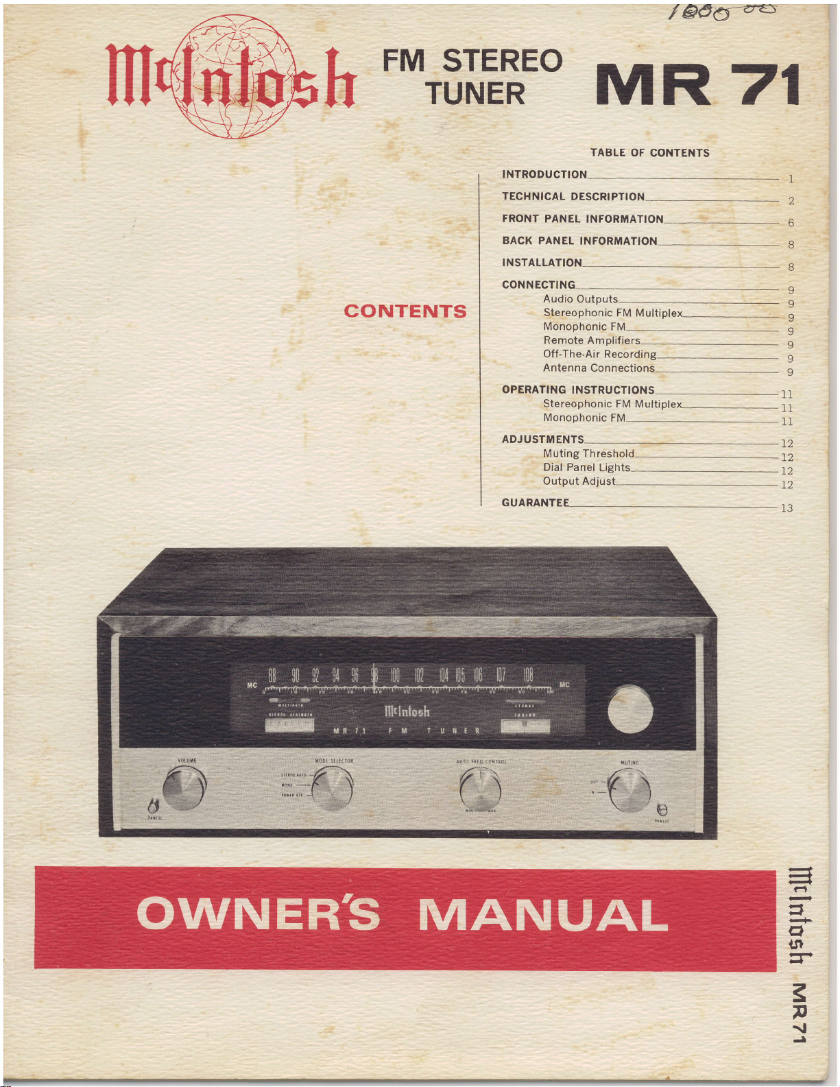
Mcintosh MR 71 Owner’s Manual
@o5:a-5
/
i
i
FM
STEREO
TUNER
CONTENTS
TABLE
INTRODUCTIONTECHNICAL
FRONT
BACK
INSTALLA
CONNECTIN
oPERAT|NG
ADJUSTMENTS
GUARAN
DESCRIPT]ON
PANEL
PANEL INFORMATION
Audio
Stereophonic
Monophonic
Remote Amplifie
Off-The-Air
Antenna
Stereophonic FM
Monophonic
Muting Threshol
Dial Panel
Output Adjust--
INFORMATION
Outputs
Connections-
TNSTRUCTTONS-_--=--
MR 7I
OF CONTENTS
FM
Multiplex
FM
Recording_
Multiplex_
FM
Lights-
11
11
I1
1l
T2
T2
IZ
T2
l3
1
2
6
8
B
9
I
v
l,
9
9
F?
a
lJr
F
-
3
p
{
-t
l-)

THANK
YOU
Judging
from
among discriminating
freshman when
to read
successful
and
partnership
equrpment.
You
have "THE BEST."
now
thousands of
you
lf
outline of
for
this manual
in ahurry,
are
what
MR 71 FM
The Mclntosh
neered,
The research staff of
has developed f ive new
ments
1.
is "clickless"
(Patent
2.
path
na
mum
3.
first
sponses.
4.
increased sensitivity which
setting
5. A new
duce noise from
carrier
tuner uses
The MR 71
lntosh PANLOC method
PANLOC
installation,
highly sensitive FM Multiplex Tuner.
for
the MR 71.
Automatic
applied
Multipath indicator to eliminate
reception by showing when
rotated
is
multipath
Double
amplifier
R.F.
New
D'Arsonval movement
adjustments.
auxiliary music
system
MR 71
stereo-mono switching that
and
for.)
to the correct
distortion.
tuned
computer
stations broadcasting
a filter.
such
also
gives you
operation, and maintenance.
is a
Mclntosh
tuner circuit
completely electronic.
position
input circuits
reduce
to
do not
designed filter
services.
uses
the exclusive Mc-
installation.
of
absolute
stereo equipment
the
music listeners.
comes
it
carefully
to stereo.
follow
these
between
hours
each control
musical enjoyment.
of
page
read
and
is 30 minutes. This
STEREO
INTRODUCTION
precision
your
spurious re-
engi-
Laboratory
improve-
multi-
anten-
mini-
for
before the
meters
need
No other
zero
to re-
sub-
The
ease
of
of
you
You are
Never-the-less
instructions
you
and
Used
properly you
first. This
3
indicator does. Reading
is time well
you
own,
your
gives you
spent.
rank high
probably
we ask
to
new
you
insure a
stereo
are in for
a brief
time
no
TUNER
PANLOC is
technique
In the PANLOC
mounted
on this shelf. Depressing
tons on the front
place
into
the
tuner depress
second
front
the
position,
the tuner from
the holding latches allows
taken
into
back
The
phonic
casts is assured
tu ner.
Once
performance
stand why Mclntosh
their reputation as "THE BEST." Your
Intosh
finest
valued
the first
to be used on stereo instruments.
first.
for normal
time. The tuner
panel,
preventing
out of the PANLOC
position
finest
possible
possible
and FM multiplex
you
have
of the MR
MR 71 tuner will
part
of
professional
system a metal
The tuner
panel
The
the
againstthe
by the Mclntosh MR 71
enjoyed the outstanding
FM
your
slides
the PANLOC
locks the tuner firmly
operation.
PANLOC
the
can
tuner
installation.
reception, and will
home
will
accidental
reception of FM mono-
stereophonic
71,
products
give you years
music
installation
into
To
buttons
now
slide
lock
release of
Depressing
the
tuner to be
shelf or to slide
mounting
you
will under-
have
system.
is
shelf
position
but-
unlock
a
from
into
this
panel.
broad-
earned
Mc-
of the
a
be
TECHNICAL
DESCRIPTION
a 6DS4
tuner
71
MR
The
the
Nuvistor
tor
form
to
of the
cascade
range
noise
A
with
reduces
value.
possible rating,
selectivity.
A
Control
As
automatically
After
gradually comes
iecond
brings
automatic
time
tion.
justable
diode
silicon
formance.
changes.
nates
temperature'compensated
tector
circuit.
narrow
tuning
muting
circuit
tion
tuning
stations
noise
muting.
be
stations.
tory
for
(triode) operates
a cascade
operating
amplifier
signals
of
ratio.
double-tuned
Nuvistor-tube
the
spurious
Sensitivity
newly
the
The
The
developed
(AFC)
circuit
tuning
station
the
interval.
tuningto
the
tuning
tuning
the
amount
The
with
circuit
AFC
place
in
diode
lt
lt has
chance
the
supplies
insures
This
band
meter
circuit.
Mclntosh
automatically
noise,
cut
set
including
in and
that
interference
and
A front
for
off
back
A
the
to
has
amplifier'
RF
first
a second
into
amplifier.
characteristics
handle
to
excellent
with
input
RF
cascade
signals
is
while
knob
cuts
is tuned
The
dial
a front
is
of
improves
unaffected
is
no
operating
detector
amplifier
developed
of
out
can't
panel
listening
correct
to
increased
still
Automatic
greatly
moved,
is
for
off
in,
operation
into
action
AFC
minimum
repeats
moved
is
action
AFC
of
panel
unique.
a conventional
the
warm-up
tube
of
signals
positive
also
and
suppresses
noises
the
a
station.
override
are
switch
to
panel adjust
muting
high-grain
Nuvis-
The
triode
Careful
a wide
circuit
extremely
an
the
to
retaining
simplifies
the
sharpest
the
automatically
distortion'
action
its
to
control'
uses
lt
overall
temperature
by
drift
filament
narrow
AFC
operates
the
ultrasonic
usually
Weak
the
suppressed
allows
weak
control
threshold
tube
design
allows
dynamic
signal-to-
combined
amplifier
highest
high
Frequency
tuning'
circuit
AFC
tuning'
circuit
AFC
over
each
new
a
fully
is
a silicon
tube'
AFC
elimi-
and
hum'
band
the
to
action'
the
ultrasonic
muting
intersta-
all
heard
distant
or
background
by
muting
and
is
the
low
a 3
This
sta-
ad'
The
per-
A
de-
AFC
The
FM
the
to
noisy
fac-
level'
mixer
The
intermediate
topped
lF transformers
The
sponse
rejection.
assures
mechanical
adequate
limiters
plete
limiters
signal-to-noise
separate
A
audio
only
frequency
wide
Both
shielded
suppression
lF
and
The
Mclntosh
this
of
adjustments
multiplex
minus
Then
main
signals
nel
separation.
A temperature
locks-in
oscillator.
noise
38KC
the
providing
ceptibility
interference
ing
highly
A
reduces
auxiliary
frequency
the
mately
27sdb
without
The
which
station
unique
output
frequency
highly
with
Construction
electrical
on
the
frequencies.
MR
circuit
right)
automatically
carrier
immunity.
50db.
per
MR
lights
circuit
selective
maximum
shock
gain
is
weakest
the
are
ratio.
wide
frequencies
resPonse'
and
RF
in excess
radiation
of
multiPlex
71
developed
is the
necessary
matrixing
stereo
signal'
then
are
highly
a
This
signal
distortion
low
spurious
to
selective
noise
music
The
octave.
affecting
has
71
when
broadcasting
using
amplified
is
stages
response
wide
have
adjacent
of the
stability
and
provided
used
band
circuits
lF
of
detector.
methods'
sidebands
combined
The
produced
stabilized
stable
method
Balanced
components
minimized
is
computer
from
services'
from
band
filter
The
normal
multiplex
a
the
a transistor
lF transformers
and
vibration'
to
signals.
for the
detector
low
for
requirements
FCC
the
of
decoder
elimination
with
left
3BKC
gives
detectors
and
signals'
stations
The
63J4KC
response
noise
program
pointer
dial
multiplex
through
flat'
with
curves'
band
channel
resistance
than
More
operate
best
distortion
are
FM
The
commonly
The
are
with
and
with
igKC
synchronous
in the
reduced
Tape
this
by
designed
broadcasting
filter
is eliminated
stereo
both
com-
Two
possible
handles
completely
oscillator
uses
advantage
critical
of
L-R
detected'
the
chan-
right
excellent
amplifier
exceptional
cancel
output,
record-
method'
reduces
approxi'
slope
material'
indicator
crosses
stereo'
operates
five
re-
to
and
for
a
used
(left
L*R
sus-
filter
is
a
A
the
2
stereo indicator lamp. The transistor
MPX
controlled
detecting bridge circuit. The circuit discriminates between noise
pilot
the 19KC signal
broadcast.
The MR 71
automatic mono-stereo switching circuit.
(Pat.
out switching
The circuit switches smoothly
when the 19KC
The
ing dial is an
exclusive
signal
distortion
tion.
reception,
rotated to reduce or eliminate the
signal. The MR 71
by a noise-rejecting
and
the 19KC
signal. The
Pend.) The
multipath
Mclntosh development. Multipath
reception causes
and
knowing
By
a directional FM antenna may
indicator will light only on
present
uses a new
switching
clicks or transients.
multiplex
signal
electron
poor
the
in a multiplex stereo
Mclntosh
is electronic with-
carrier
indicator on
ray tube. This
moderate
stereo channel separa-
presence
multipath indicator
differential
multiplex
developed
and
present.
is
the tun-
to severe
multipath
of
multipath
is
silently
is
an
be
shows
if there
rapid fluctuation
With the
indicator
showing
eliminated.
Two
back
only by
other
back
feedback
nels
than sufficient output volume is available
feed
A new type of mechanical
gives
tuning action. The
directly, and in
lash
lined
duce friction and
smooth and
are multipath
of the electron
antenna
beams
that
pairs
panel.
front
the
pair
of
panel
output adjust controls.
type
provide
poweramplif
the MR
is
eliminated
pointer
remain relatively
multipath distortion
audio output
of
pa.ir
One
panel
jacks
preamplifiers
low impedance outputs.
iers as wellas
71 extremely smooth
tuning
turn
with
carriage
wear to
quiet
dial action.
signals
correctly
jacks
of
volume
is controlled
capacitor is
drives
the
this
and nylon
give
present
ray
beams.
positioned,
steady,
has been
jacks
are
on
is
controlled
control. The
only by
Two stage
on both chan-
More
preamplifiers.
tuning
design.
assembly
flywheel
driven
pointer.
an unusually
Back-
A
teflon
pulleys
by
the
the
the
to
re-
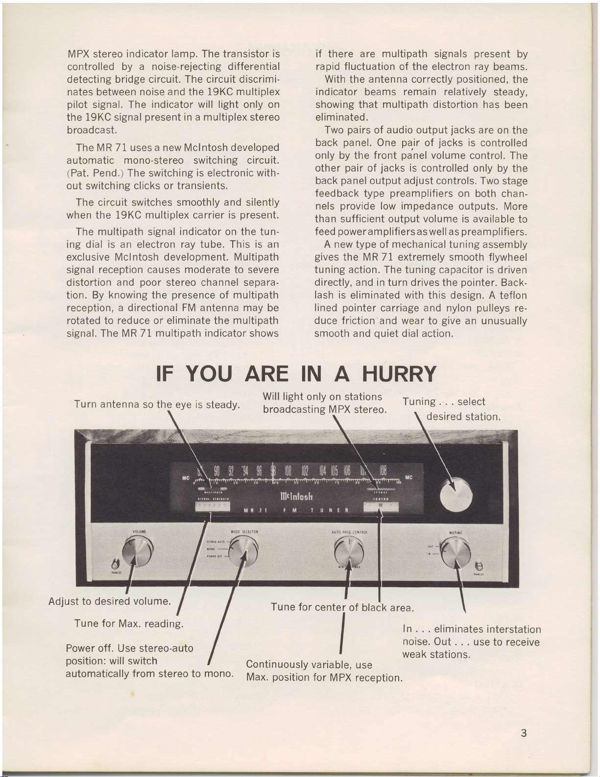
Turn antenna
Adjust to
desired
for
Tune
Power
position:
automatically from
off.
will
Use
IF YOU ARE IN A HURRY
so the
volume.
Max. reading.
stereo-auto
switch
eye is steady.
stereo to
mono.
Will light only
broadcasting M PX
for
^at
vari
for
Tune
Continuously
position
Max.
on stations
stereo.
lle
nl
te
r
black area.of
I
ablr
)lg,
ia
MP,
PX
reception.
Tuning...select
desired
ln...
noise.
weak
statio n s.
eliminates
Out...usetoreceive
station.
interstation
SPECIFICATIONS
Useable
2.5
deviation)
harmonic
IHF standards.
Audio
Within
Distortion
Less
deviation
Capture
1.5db
Muting
lF
noise
Oscillator
Less than
gible
lmage
70db
Hum
Output
Antenna
RF Amplifier
lF Stages
Limiters
Radiation
Multiplex
Multiplex
Multiplex
Multiplex
SCA Filter
Sensitivity
microvolts
for less than3/s
distortion
Frequency
lzdb
n O.5/o
tha
Ratio
at IOO%
injected
Better
Better
Approximately
300
Cascode
Five,
response.
Two.
Substantially
Better
Greater
pilot
Front
19KC
by
Peak-detecting,
50db
octave
ultrasonic
reduction
Drift
25KC
AFC
with
Rejection
than
105MC.
at
than
lnputs
balanced;
ohms
with
with
Channel
than 30db
Filter
than 48db
and
38KC
Indicator
panel
carrier-only.
Type
down
slope.
at 100%
ResPonse
from
atloo%mod
modulation.
in oPeration.
80db
70db
2.5
6DS4
200KC
below
multiplex
at 67KC
modulation
in accordance
to
20
muting:
between
AFC
with
at
below
volts;
75
Nuvistor
bandwidth,
FCC requirements.
Separation
at 1000
suppression
carrier.
stereo
self'matrixing
lo 74KC
total
20,000
u lation
at least
stations'
disabled;
90MC;
lOOTo
impedance'
low
ohms
in
cYcles.
light
(+
75KC
and
noise
with
cycles.
KC
75
t
60db
negli'
better
modulation.
unbalanced.
detector.
275db
than
first stage'
flat toP
19KC
of
activated
Per
Automatic
An exclusive
electronic
ing
Tube and
1-6DS4
I-72Af7
1-6BN4A,
1-6AU6,
1-6AU6,
1-6AU6,
1-6AU6,
1-6CS6, 5th
1-6BN8,
2-6818,
1-6U8,
i-6HU6/EM87
I-I2AU7,
1-ST2-27
1-MAi 13
2-IN542
2-1N542
4-IN542
2-LN542
2-Selenium
1-No.
Power Gonsumption
70
Dimensions
Front
high; chassis
inches
deep,
front of
172
Weight
Chassis
In shipping
Mono-Stereo
Mclntosh
automatic
(Pat.
circuit.
Semiconductor
Nuvistor,
,2nd
2nd
3rd
4th
Detector,
Left
Audio
Control.
Amplifiers.
MPX
Switch.
Lamp
Discriminator
Discriminator.
Detector.
Indicator.
MPX
Power
1850
watts,
Panel;
wide by 5
including
mounting
inches.
only, 27
Pend.).
RF
Oscillator.
lF.
1st
lF.
lF.
lF
lF 2nd
Muting
AVC ClamPer.
and Right,
Amplifier,
PX
M
Voltage
5,
(Transistor),
Diodes,
Diodes,
Diodes,
Diodes,
Rectifiers,
Supply.
Lamp, MPX
to 125
105
16
(including
carton, 37
Switch
development;
mono-stereo
Gomplement
RF.
1st
and Mixer.
and 1st
AmPlifier,
Multipath
Oscillator'
inches
inches
connectors;
pounds.
Limiter.
Limiter
Muting
1st
MPX
I ndicator.
Reference.
MPX
Band
Wide
Narrow
Balanced
Balanced
panel
Band
High
Indicator'
50 to
volts,
wide by
PANLOC
high
including
Pounds.
and 2nd
MPX
all'
switch-
and
Muting.
Indicator
ndicator
I
Detector
Voltage
5%s
by 13
clearance
for
cycles.
60
inches
shelf)
inches
knobs.
15
in
4

o
=
\
o
l!
o
.E
ff,
\-a-a-a-/
.UUf''
o
z
o
\-A-a-a-,
\
.fur\
o
()
=
\-a-A-A-/
.6fn
(IF-
!s!
=g
()
E
@
I
6
@
(L
=
l!
E
.L
=
l!
E
o
=
@
6
I
@
@
U-A-A-/
rUUU'\
(o
f
(o
(o
l
(o
(o
-*(,
@
ffir-
t-
NF
----t(9
\<
g
sl
(t
o
@
Itsl
K.Hr'
U
C)
o
(9
o
.l
z.l
I
\____.]
I
Ir
I
I
Iri
I
I
\____l
--l
I
I
I
l<
iA=F
-\_-/
FZ
z-
l'*
E.
=
E.
/11
L]
]<
O
o
tl.l
E,
o
E+
-z
=ct
8(o
o
C)
=
\
I
I
\
(o
o
q9
HEfH
'5Eu
t-qn|lr
--J
H
(.)
+
Y
|()
o
z
C)
\-A.A
9.)
Y
o
.|tu
r\
.E
9oP
6Y=
soo
:=
EEF
(\l
o-
at
c
F
=
=
tr
o
a
E
\.!
.l
Tir\
(o
v,
o
@
\-A-a.q-l
rrur\
=-
l
(o
F
T'
o=E
o
=
F
!Tl!
_
6IIJ
z=arE
i]
t-
I(
t:
lr
l(
L-
-ff1
'/)l-
_
-ii
E3
E.
O.J
kt9
PrE
eff
dE
JO;:
d*a
o
s*
J
*8H
=85
T
.,,I
oa
6!
zl
o
o
d<
=
(,
z
.E
9P'
trH6
JF(o
=ld
o
oP
z*
dtJ
(o(L
gE
;tr
g.
F
z
=
E
C)
I
o
.L
F
o
(,
F
Ff,
L(L
lr,
J=l
F
o
F
(L
(9
F
(!
f
o
qd'
E
UJ
5
J
q^ul
(lt==
(o=J
E<g
.E
+
|r,
z_
\P
isi
-@rJ
s'"g
o
TE
l.- Or
L=
{:iE
s-gg
@^trJ
Eo+
e=+
E<=
ll
tt
tl
-----z--
o-
:)
j
u,
6
U
lrl
o
E
E
l|
|
dF-
l!
2
t
xo
5cb
HEH
=uJ
o
ti
<Fl
()
i
r
3oH
.I!==
@5#
Q<=
@hJ
JOi;@==
(o=-l
E<g
9.
U'
U
u
o
:a
E
!
I
lr
z
j
I
G
*qrF
8#a
(E
.hP
:fd<
-to
o-:
o-
=z
-3gE
\La,/(9Hld
-
@F=
at,
(L
(J
@
o
(t
tr
5
 Loading...