

Page 1
Enviromental Equalizer
OWNERS
MANUAL
MQ109B
McIntosh Laboratory, Inc. 2 Chambers Street Binghamton, New York 13903-2699 Phone: 607-723-3512 FAX: 607-724-0549
Page 2

Thank You, Please Take A Moment,
Customer Service and Table of Contents
Thank You
For your decision to own this McIntosh MQ109B
Enviromental Equalizer ranks you at the very top among
discriminating music listeners. You now have The Best.
The McIntosh dedication to Quality, is assurance that you
will receive many years of musical enjoyment from this
unit.
Please take a short time to read the information in this
manual. We want you to be as familiar as possible with all
the features and functions of your new McIntosh MQ109B.
This will ensure that you receive all the performance benefits this equipment can offer you, and that it will become a
highly valued part of your home entertainment system.
Please Take A Moment
The serial number, purchase date and McIntosh dealer name
are important to you for possible insurance claim or future
service. The serial number is located on the rear panel of the
equipment. The spaces below have been provided for you to
record that information:
Serial Number:
Table of Contents
Thank You.......................................................................... 2
Please Take a Moment ....................................................... 2
Customer Service ............................................................... 2
Table of Contents ............................................................... 2
Safety Instructions ............................................................. 3
Introduction ........................................................................ 4
Performance Features ........................................................ 4
Installation ......................................................................... 4
Side and Rear Panel Connections ...................................... 5
How to Connect ................................................................. 6
Front and Panel Controls and Switches ............................. 7
How to Operate .................................................................. 8
Specifications ................................................................... 11
Packing Instruction .......................................................... 11
NOTES:
1. Balanced and Unbalanced Outputs can be mixed.
For example, you may also use Balanced and
Unbalanced outputs simultaneously, connected to
different power amplifiers.
Purchase Date:
Dealer Name:
Customer Service
If at any time you have questions about your MQ109B
Enviromental Equalizer, please contact:
McIntosh Laboratory, Inc.
2 Chambers Street
Binghamton, New York 13903
Phone: 607-723-3512
FAX: 607-724-0549
Copyright 1997 ã by McIntosh Laboratory, Inc.
2
Page 3
IMPORTANT SAFETY
INSTRUCTIONS!
Safety Instructions
8. Do not use attachments not recommended in this
owners manual as they may cause hazards.
PLEASE READ THEM BEFORE
OPERATING THIS EQUIPMENT.
WARNING SHOCK HAZARD DO NOT OPEN.
AVIS RISQUE DE CHOC NE PAS OUVRIR.
NO USER-SERVICEABLE
PARTS INSIDE. REFER
SERVICING TO
QUALIFIED PERSONNEL
General:
1. Read all the safety and operating instructions, contained
in this owners manual, before operating this equipment.
2. Retain this owners manual for future reference about
safety and operating instructions.
3. Adhere to all warnings and operating instructions.
4. Follow all operating and use instructions.
5. Warning: To reduce risk of fire or electrical shock,
do not expose this equipment to rain or moisture.
This unit is capable of producing high sound pressure
levels. Continued exposure to high sound pressure
levels can cause permanent hearing impairment or
loss. User caution is advised and ear protection is
recommended when playing at high volumes.
6. Caution: to prevent electrical shock do not use this
(polarized) plug with an extension cord, receptacle or
other outlet unless the blades can be fully inserted to
prevent blade exposure.
Attention: pour pevenir les chocs elecriques pas
utiliser cette fiche polarisee avec un prolongateur, une
prise de courant ou un autre sortie de courant, sauf si
les lames peuvent etre inserees afond ans en laisser
aucune partie a decouvert.
7. For added protection for this product during a lightning
storm, or when it is left unattended and unused for long
periods of time, unplug it from the wall outlet and disconnect the antenna or cable system. This will prevent
damage to the product due to lightning or power line
surges.
Installation:
9. Locate the equipment for proper ventilation. For example, the equipment should not be placed on a bed,
sofa, rug, or similar surface that may block ventilation
openings; or, placed in a built-in installation, such as a
bookcase or cabinet, that may impede the flow of air
through the ventilation openings.
10. Locate the equipment away from heat sources such as
radiators, heat registers, stoves, or other appliance (including amplifiers) that produce heat.
11. Mount the equipment in a wall or cabinet only as described in this owners manual
12. Do not use this equipment near water; for example,
near a bathtub, washbowl, kitchen sink, laundry tub, in
a wet basement or near a swimming pool, etc.
13. Do not place this product on an unstable cart, stand,
tripod, bracket, or table. The equipment may fall, causing serious injury to a person, and serious damage to
the product.
Connection:
14. Connect this equipment only to the type of AC power
source as marked on the unit.
15. Route AC power cords so that they are not likely to be
walked on or pinched by items placed upon or against
them, paying particular attention to cords at plugs, convenience receptacles, and the point where they exit from
the instrument.
16. Do not defeat the inherent design features of the polarized plug. Non-polarized line cord adapters will defeat
the safety provided by the polarized AC plug. If the
plug should fail to fit, contact your electrician to replace your obsolete outlet. Do not defeat the safety purpose of the grounding-type plug.
17. Do not overload wall outlets, extension cords or integral convenience receptacles as this can result in a risk
of fire or electric shock.
Care of Equipment:
18. Clean the instrument by dusting with a dry cloth. Unplug this equipment from the wall outlet and clean the
panel with a cloth moistened with a window cleaner. Do
not use liquid cleaners or aerosol cleaners.
19. Do not permit objects of any kind to be pushed and/or
fall into the equipment through enclosure openings.
3
Page 4

Safety Instructions cont, Introduction,
Performance Features and Installation
Never spill liquids into the equipment through enclosure
openings.
20. Unplug the power cord from the AC power outlet when
left unused for a long period of time.
Repair of Equipment:
21. Unplug this equipment from the wall outlet and refer
servicing to a qualified service personnel under the following conditions:
A. The AC power cord or the plug has been damaged,
B. Objects have fallen, or liquid has been spilled into
the equipment,
C. The equipment has been exposed to rain or water,
D. The equipment does not operate normally by follow-
ing the operating instructions contained within this
owners manual. Adjust only those controls that are
covered by the operating instructions, as an im-
proper adjustment of other controls may result in
damage and will often require extensive work by a
qualified technician to restore the product to its nor-
mal operation,
E. The equipment has been dropped or damaged in any
way,
F. The equipment exhibits a distinct change in perfor-
mance - this indicates a need for service.
22. Do not attempt to service beyond that described in the
operating instructions. All other service should be referred to qualified service personnel.
23. When replacement parts are required, be sure the service technician has used replacement parts specified by
McIntosh or have the same characteristics as the original part. Unauthorized substitutions may result in fire,
electric shock, or other hazards.
24. Upon completion of any service or repairs to this product, ask the service technician to perform safety checks
to determine that the product is in proper operating condition.
usually at frequencies of 1200Hz and lower. and can alter
frequency response as much as ± 30dB.
Standing waves or room resonances occur due to reflections of the sound from wall to wall, from floor to ceiling
and from any other room structures. These frequency response variations are the greatest in a cube shape room,
with equal dimensions from wall to wall and floor to ceiling.
A high quality loudspeaker with the ability to radiate perfectly uniform frequency response can have its sound characteristics changed drastically by a room with severe standing waves. In most every case the change will degrade the
listening. The most common effect is one or more peaks/dips
in the bass frequency range.
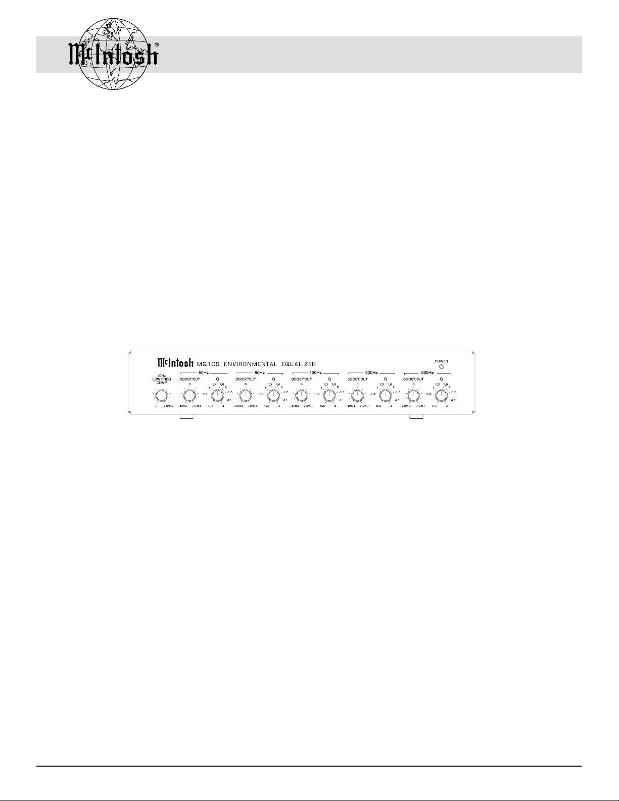
Performance Features
· Low Frequency Compensation
Low Frequency Compensating Control centered at 30Hz
allows bass centered at 30Hz to be boosted by up to 12dB.
· Five Equalizer Bands
Five Equalization bands centered at 50Hz, 80Hz, 150Hz,
300Hz and 600Hz. provide adjustment for the five most significant frequency bands which are affected by room acoustics.
· Variable Equalizer Controls
Five Boost and Cut Controls, one for each band. Each of
the five frequency bands can be boosted or cut by up to
12dB.
· Variable Q Controls
Five Q controls, one for each band. The Q or bandwidth of frequencies above and below the center frequencies
can be adjusted from a narrow with Q of 4 to a broad
bandwidth with a Q of 0.6.
Introduction
The MQ109-B Environmental Equalizer provides an easy
and convenient way to correct room acoustic conditions that
can affect the performance of a quality loudspeaker system.
Loudspeaker performance is affected by the listening room
due to loudspeaker location, position of the listener, room
dimensions, room surfaces, and reflections from furniture or
substructures in the room. The acoustic characteristics of a
typical listening room can affect loudspeaker performance
4
· Balanced and Unbalanced Connections
Both Balanced and Unbalanced Inputs and Outputs are provided.
Installation
The MQ109B can be placed upright on a table or shelf.
Cool operation ensures the longest possible operating life
for any electronic instrument. Do not install the MQ109B
directly above a heat generating component such as a high
powered amplifier.
Page 5

MQ109B Rear and Side Panel Connections
MQ109B Rear and Side Panel
Connections
BALANCED OUTPUTS
connect to the Inputs of a
Power Amplifier.
BALANCED INPUTS
connect to the Outputs of
a Preamplifier or Control
Center.
POWER ON/OFF
switch turns power
on and off to the
MQ109B
UNBALANCED OUTPUTS
connect to the Inputs of a
Power Amplifier.
UNBALANCED INPUTS
connect to the Outputs of a
Preamplifier or Control
Center.
To AC outlet
5
Page 6

How to Connect the MQ109B
1. Connect the AC power cord to a switched outlet on a
Control Center, Preamplifier or Power Control unit. Refer to information on the MQ109-B side panel to determine the correct voltage for your unit.
How to Connect the MQ109B
2. Connect the MQ109-B INPUTS to the Outputs of a
Preamplifier or Control Center.
3. Connect the MQ109-B OUTPUTS to the inputs of a
Power Amplifier.
NOTE: Either Balanced or Unbalanced Inputs and Outputs
can be used. You can intermix Balanced and
Unbalanced connections. For example, use
Unbalanced Inputs and Balanced Outputs.
To AC Outlet
NOTE: Optional connecting methods are through a signal
processor loop or tape monitor loop.
McIntosh Preamplifier
McIntosh Power Amplifier
(Left Channel)
Power Amplifier
Top View
insert
6
McIntosh Power Amplifier
(Right Channel)
Page 7

MQ109B Front and Side Panel Controls and
Switches
30Hz LOW FREQ COMP, (Low
Frequency Compensation) boosts
bass response centered at 30Hz as
much as 12dB.
The Q controls can
widen or narrow the
bandwidth of each of
the five frequency
bands.
MQ109B Front and Side Panel
Controls and Switches
POWER ON LED
BOOST/CUT controls
can increase or decrease
the volume level of each
of the five frequency
bands by 12dB.
POWER
switch turns
all AC power
completely
ON or OFF.
7
Page 8

How to Operate the MQ109B
How to Operate the MQ109B
The most effective means for accurately setting the
MQ109B controls is by use of a One Third Octave Pink
Noise Generator and calibrated sound level pressure meter.
A one third octave real time analyzer can also be used. The
pink noise generator output is connected to the preamplifier
or control center, (set for flat response), and on to the power
amplifier and speakers. The sound level microphone should
be located in the primary listening area.
1. Measure the backround noise level in the room.
2. Adjust the output level of the pink noise generator until
the output is at least 20dB above the backround noise
level in the room, as measured in step one.
NOTE: The Pink Noise Generator should be set to broad
band noise.
3. Adjust the output of
the pink noise generator for one third
octave noise.
4. Sweep the frequency
range of the pink
noise generator
from 20Hz to
10,000Hz.
Select the MQ109B BOOST/CUT control that is closest
to the frequency of each of the undesired peaks or dips in
response and adjust them as needed to correct the amplitude
deviations. Refer to figure 1.
5. Adjust the appropriate Q controls to compensate for the
bandwidth of the peak or dip.
6. Adjust the LOW FREQ COMP control to achieve the
best possible low frequency response.
NOTE: Figures 2 through 8 show the frequency range,
bandwidth and amplitude characteristics of each of the
MQ109B controls.
It will be necessary to repeat steps 4 through 6 as often as
necessary to confirm that the equalization adjustments have
corrected the response deviations.
The room sound level
measurements will indicate the frequency response of the system
and reveal the specific
frequency ranges where corrective equalization is needed.
The variation from the ideal may be either a peak or a dip
in the response at more than one frequency. The variations
can also be of different amplitudes, and may be broad or
narrow in bandwidth..
NOTE: Do not try to adjust for a perfectly flat response from
20Hz to 20,000Hz as this will result in a totally
unnatural sound quality. Rather adjust for a smooth
response.
8
Figure 1
Page 9

Figure 2
30 Hz Low Frequency Compensation
How to Operate the MQ109B, cont
100Hz 1000Hz 10000Hz
Figure 3
50Hz Maximum Boost/Cut
50Hz Maximum Q and Minimum Q
Figure 4
80Hz Maximum Boost/Cut
80Hz Maximum Q and Minimum Q
100Hz 1000Hz 10000Hz
100Hz 1000Hz 10000Hz
9
Page 10

Figure 5
150Hz Maximum Boost/Cut
150Hz Maximum Q and Minimum Q
How to Operate the MQ109B, cont
100Hz 1000Hz 10000Hz
Figure 6
300Hz Maximum Boost/Cut
300Hz Maximum Q and Minimum Q
Figure 7
600Hz Maximum Boost/Cut
600Hz Maximum Q and Minimum Q
100Hz 1000Hz 10000Hz
10
100Hz 1000Hz 10000Hz
Page 11

NOTE: The following table may be used to record your
adjustments for future reference.
Specifications and Packing Instructions
Maximum Input Signal
2.5V
&RQWURO 'HIDXOW 6HWWLQJ 1HZ6HWWLQJ
+]/RZ)UHT&RPS G%
+]%RRVW&XW G%
+]4
+]%RRVW&XW G%
+]4
+]%RRVW&XW G%
+]4
+]%RRVW&XW G%
+]4
+]%RRVW&XW G%
+]4
Low Frequency Compensation
+12dB maximum at 30Hz
Equalizer Center Frequencies
50Hz, 80Hz, 150Hz, 300Hz and 600Hz (± 5%)
Boost/Cut Range
± 12dB at center frequency (± 5%)
Q Control Range
0.6 to 4 (± 5%)
Power Requirements
100 Volts, 50/60Hz at 7 watts.
110 Volts, 50/60Hz at 7 watts.
120 Volts, 50/60Hz at 7 watts.
220 Volts, 50/60Hz at 7 watts.
230 Volts, 50/60Hz at 7 watts.
240 Volts, 50/60Hz at 7 watts.
NOTE: Refer to the side panel of the MQ109B for the correct
voltage
Specifications
Frequency Response
± 0.5dB from 20Hz to 20,000Hz (equalization set to flat)
Total Harmonic Distortion
0.004% From 20Hz to 20,000Hz (at rated output)
Signal To Noise Ratio, A-Weighted
100dB below rated output of 2.5V (equalization set to flat)
98dB below rated output of 2.5V (worst case setting)
Maximum Voltage Output
6.5V from 20Hz to 20,000Hz (balanced and unbalanced
outputs)
Output Impedance
600 ohms (balanced and unbalanced outputs)
Sensitivity
2.5V for 2.5V rated output (equalization set to flat)
Input Impedance
47K ohms
Dimensions
12.4 (31.5cm) W, 7.3 (18.5cm) D, 2.3 (5.8cm) H
Weight
6 lbs net, 7 lbs in shipping carton
Packing Instructions
In the event it is necessary to repack the equipment for shipment, use the original shipping carton and packing material
only if they are in good serviceable condition. If a shipping
carton or packing material are needed, please call or write
Customer Service Department of McIntosh Laboratory and
order the following:
Quantity Part Number Description
1 033939 Shipping carton
1 033085 Bubble Pack
11
Page 12

McIntosh Laboratory, Inc.
2 Chambers Street
Binghamton, NY 13903
McIntosh Part No. 04038201
 Loading...