

Page 1
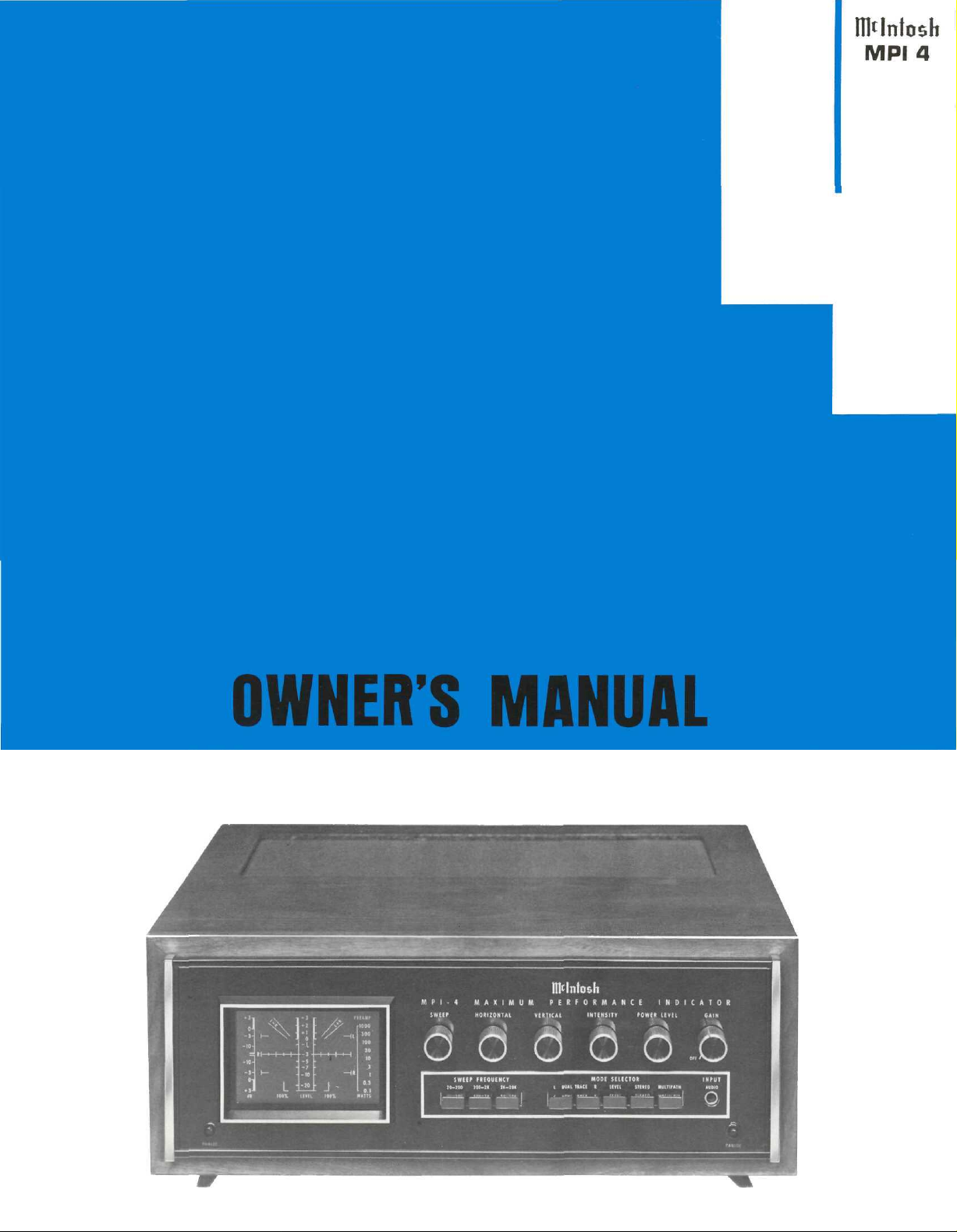
THE MclNTOSH MPI 4 MAXIMUM PERFORMANCE INDICATOR
Reading Time 40 Minutes
Price $1.25
Page 2

Page 3

Your MPI 4 Maximum Performance
Indicator will give you many years of
pleasant and satisfactory performance.
If you have any questions concerning the
operation or maintenance of this
instrument, please contact:
CUSTOMER SERVICE
Mclntosh Laboratory Inc.
2 Chambers Street
Binghamton, New York 13903
Phone: 607-723-3512
Take Advantage of 3 years
of FREE Factory Service . . .
Fill in the Application NOW.
contents
GUARANTEE ... 1
GENERAL ... 2
INSTALLATION ... 2, 3
HOW TO CONNECT . . . 3-5
FRONT PANEL INFORMATION ... 6-8
LEVEL SET PANEL INFORMATION ... 8
REAR PANEL INFORMATION ... 9
INITIAL SETUP ... 9, 10
HOW TO USE THE MPI 4 ...
PERFORMANCE LIMITS ... 18, 19
TECHNICAL DESCRIPTION ... 19, 20
BLOCK DIAGRAM ... 21
10-18
Guarantee
Mclntosh Laboratory Incorporated guarantees this instrument
to be capable of performance as advertised. We also guarantee
the mechanical and electrical workmanship and components to
be free of defects for a period of 90 days from date of purchase.
If such defects occur, Mclntosh Laboratory or one of its authorized
THREE YEAR FACTORY SERVICE CONTRACT
An application for a FREE THREE YEAR FACTORY SERVICE
CONTRACT is included with this manual. The terms of the contract
are:
For Three Years from date of purchase—
1. Mclntosh will provide all parts, materials and labor needed
to return the measured performance of the instrument to the
original performance limits free of any charge. The SERVICE
CONTRACT does not cover any shipping costs to and from
the authorized service agency or the factory.
2. Any Mclntosh authorized service agency will repair all Mclntosh instruments at normal service rates. To receive the free
service under the terms of the SERVICE CONTRACT, the
SERVICE CONTRACT CERTIFICATE must accompany the instrument when taken to the service agency.
3. Always have service done by a Mclntosh authorized service
agency. If the instrument is modified or damaged, as a result
of unauthorized repair the SERVICE CONTRACT will be cancelled. Damage by improper use or mishandling is not covered
by the SERVICE CONTRACT.
agencies will repair the defect at no cost to the purchaser. This
guarantee does not extend to components damaged by improper
use nor does it extend to transportation to and from the factory
or service agency.
4. The SERVICE CONTRACT is issued to you as the original
purchaser. To protect you from misrepresentation this contract
cannot be transferred to a second owner.
5. The SERVICE CONTRACT is given to purchasers who live
in the 50 United States or Canada only.
6. For your protection Mclntosh selects its dealers carefully.
Only one dealer in ten qualifies for a Mclntosh franchise,
To receive the SERVICE CONTRACT your purchase must be
made from a Mclntosh franchised dealer.
7. Your completely filled in application for a SERVICE CON-
TRACT must be postmarked within 30 days of the date of
purchase of the instrument.
8. To receive the SERVICE CONTRACT all information on the
application must be filled in. The SERVICE CONTRACT will
be issued when the completely filled in application is re-
ceived at Mclntosh Laboratory Incorporated in Binghamton,
New York, If the application is not received at Mclntosh
Laboratory, only the service offered under the 90-day guarantee will apply.
Copyright © 1973 By Mclntosh Laboratory Inc.
1
Page 4
General
installation
The MPI 4 is a laboratory-grade instrument. It provides
the facility to continuously monitor the quality of the performance of a stereo system. The MPI 4 can sample and dis-
play signals from the tuner, preamplifier and power amplifier without reconnecting cables. Signals are displayes on an
oscilloscope screen calibrated with scales for tuning,
measuring and testing.
As a tuning aid, the instrument is a guide to exact FM
station selection and precise tuning. The screen displays
FM signal strength, modulation percentage and mulitpath
interference. Audio signals may be viewed for stereo balance, strength, phase and channel separation. Output power
of the power amplifier can be seen at any instant during
program performance, or stored to develop a trend over
several minutes.
With the addition of test records, the MPI 4 can show
compliance and trackability of a phono pickup, frequency
response of the preamplifier and power amplifier, audio
distortion and stereo speaker balance.
In one of its operational modes, the MPI 4 becomes a
"dual trace" oscilloscope. When operated in the dual trace
mode the left and right stereo channels appear simul-
taneously and separately on the screen for direct comparison. The instrument also has "triggered sweep." It permits
the viewer to choose a single tone and lock it on the screen
for careful inspection.
In a search for convenient equipment-mounting tech-
nique, Mclntosh developed the PANLOC system. Pressing
the two PANLOC buttons on the front panel of the MPI 4
releases the unit to slide in or out of its mounting. This
allows easy access to cable connections at the rear. It
brings top panel controls into view for easy adjustments,
adjustments.
Ventilation extends the trouble-free life of an instru-
ment by preventing excessive internal temperature and
insulation breakdown. To accomplish this, allow cool air
to enter at the bottom of the instrument and warm air to
escape at the top. The MPI 4 Maximum Performance Indicator may be mounted in any position. It requires a
mounting space 15 inches deep (38.1 cm), 17½ inches
wide (44.45 cm), and 6 inches high (15.24 cm).
To mount in the Mclntosh cabinet follow the instructions enclosed with the cabinet. For any other installation,
remove the instrument, PANLOC brackets, parts bag and
mounting template from the carton. Remove the MPI 4
from the plastic bag and place it upside down on the
shipping pallet. Then remove the four plastic feet fastened
to the bottom of the chassis.
1. POSITION TEMPLATE AND MARK
Position the plastic mounting template over the area of
the cabinet panel where the MPI 4 is to be installed.
Be sure that the edges of the equipment marked on the
template clears any shelves, partitions or existing
equipment located behind the panel. With the template
in place mark the six "A" and "B" holes and four smalt
holes locating the corners of the cutout. Next, join the
four corner marks with pencil lines. The edge of the
template is used as a straight edge.
2. DRILL HOLES
With the drill perpendicular to the panel, drill the
six "A" and "B" holes using a 3/16 inch drill. THE
SIX HOLES MUST BE DRILLED BEFORE MAKING
THE CUTOUT.
2
Page 5
3. SAW CUTOUT
Carefully cut the rectangular opening on the inside of
the pencilled rectangle.
How to connect
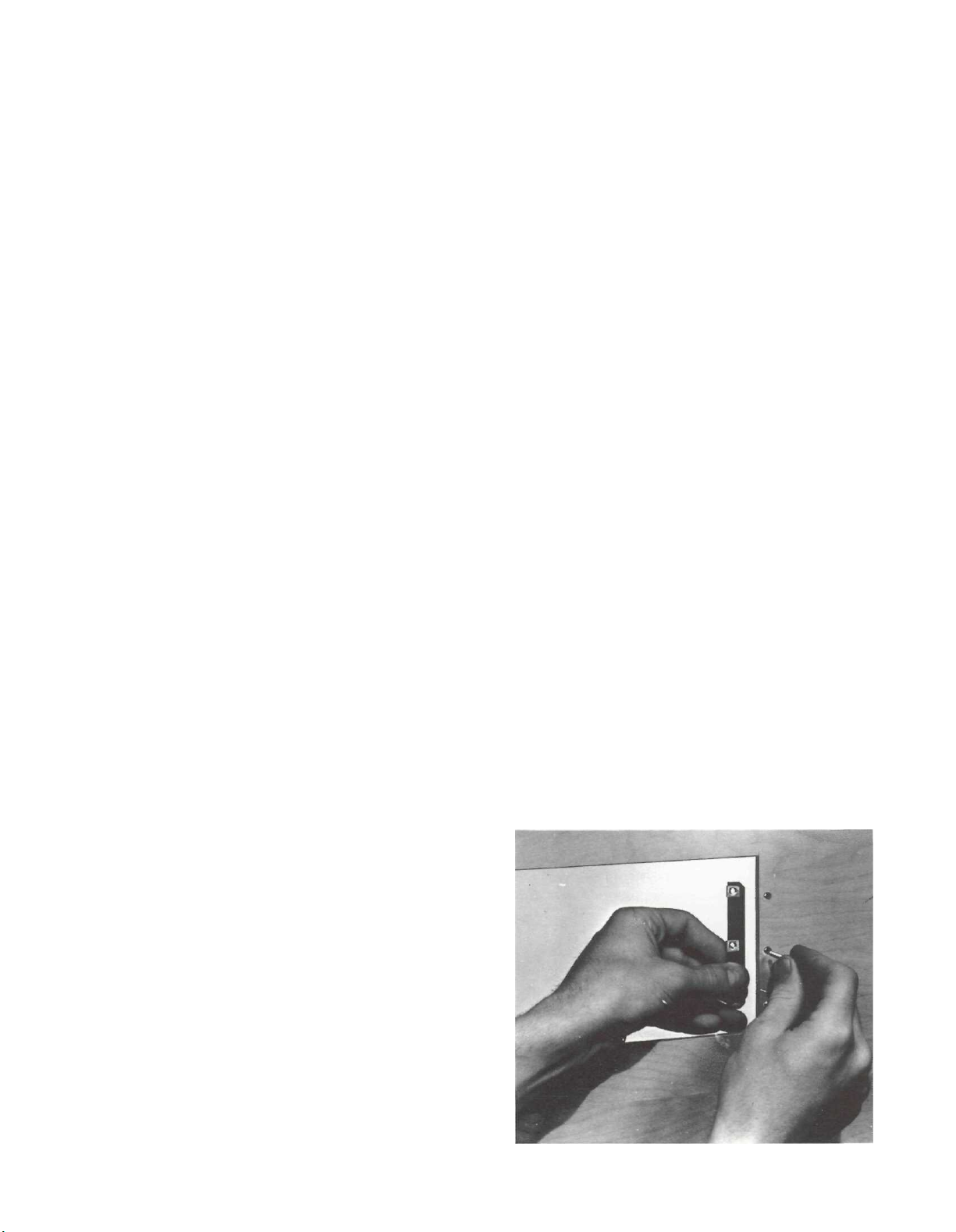
4. SECURE MOUNTING STRIPS
Install the mounting strips (supplied in the hardware
package) on the inside of the cabinet panel. Insert
two screws (supplied in the hardware package) into
the center holes ("B" holes on the template). Use the
¾-inch long screws for panels under ½-inch thick or
1¼-inch screws for panels ½-inch thick or over. Place
a mounting strip on the back of the cabinet panel.
Align it with the three holes in the panel and tighten
the screw. The screw head should pull slightly into the
wood panel. Attach the other mounting strip by repeating the procedure.
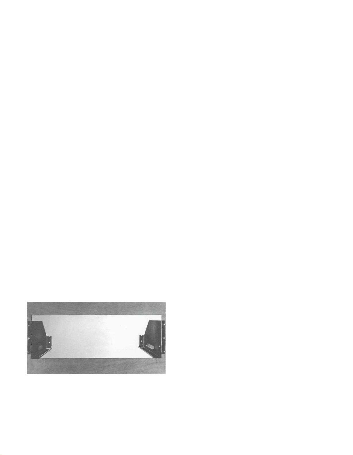
5. MOUNT THE PANLOC BRACKETS
Attach the PANLOC brackets to the cabinet panel
using four screws of the proper length. Place the template over the mounting screws. The screws should
be centered on the "A" and "B" holes in the template.
If necessary, loosen the screws and push the mounting
brackets into alignment then retighten.
6. INSTALL THE UNIT
Thread the power cord through the opening in the
cabinet panel. Carefully slide the instrument into the
opening so the rails on the bottom of the instrument
engage the track on the mounting brackets. Slide the
instrument in until it stops at the ad|ust position
latches. Press the latches in and continue to slide the
instrument until its front panel is flush with the cabi-
net panel. At the bottom front corners are the PANLOC
buttons. Depressing the PANLOC buttons will lock the
instrument firmly in the cabinet panel. Pressing the
PANLOC buttons a second time will release the instru-
ment You can then slide the instrument forward to the
adjust position. Pressing the adjust position latches
will allow the instrument to be removed from the
cabinet.
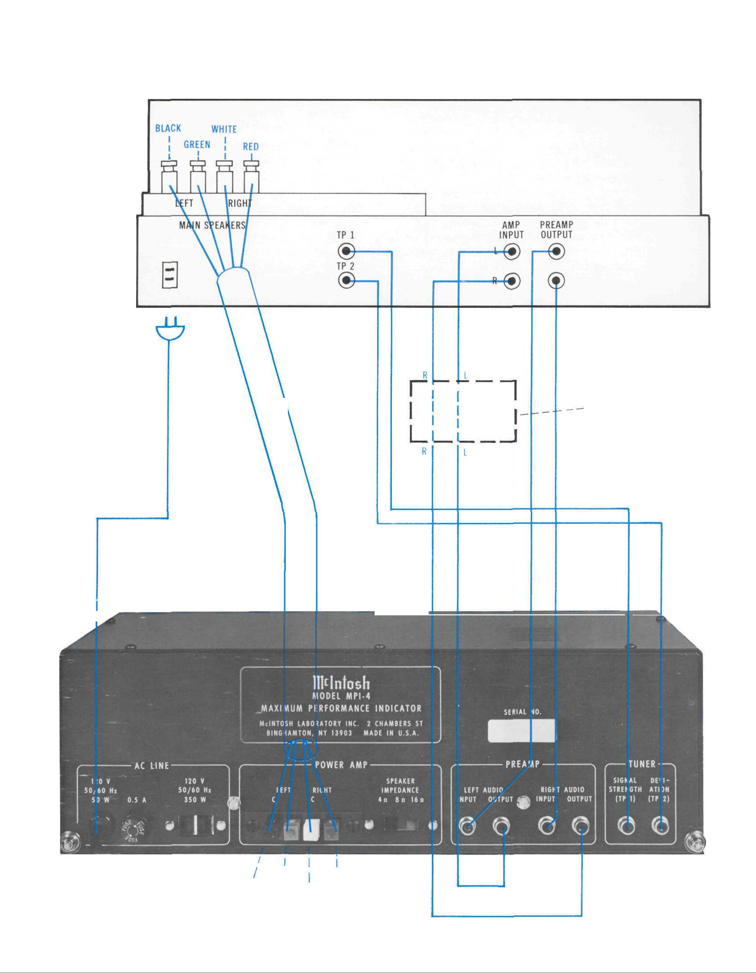
The MPI 4 may be connected to a stereo receiver (Fig.
1) or to a component system with a separate preamplifier and power amplifier (Fig. 2). Choose which most
closely resembles your system.
AUDIO INPUTS
Low Level Audio Input
Use one of the 6-foot shielded cables supplied, to connect the left channel output on your preamplifier to the
LEFT AUDIO INPUT on the MPI 4 back panel. Similarly,
connect the right channel preamplifier output to the
RIGHT AUDIO INPUT.
SPEAKER INPUT
There are four color-coded push connectors on the back
panel of the MPI 4. Connect these with two pairs of speaker
cables to the left and right output on the power amplifier.
Black Left speaker common terminal
Green Left speaker high terminal
White Right speaker common terminal
Red Right speaker high terminal
Set the SPEAKER IMPEDANCE switch on the MPI 4 back
panel to agree with the speaker system impedance: 4W,
8W, or
16W.
TUNER INPUTS
Signal Strength Input
Mclntosh tuners and receivers provide signal for the
SIGNAL STRENGTH INPUT at a connector marked TP 1
on the back of each tuner. Using the 3-foot low-capacity
shielded cable supplied, connect the TP 1 output to the
SIGNAL STRENGTH INPUT.
TO PREVENT HIGH FREQUENCY LOSSES, THE SPECIAL
3-FOOT CABLES SUPPLIED MUST BE USED. DO NOT
SUBSTITUTE ORDINARY AUDIO CABLE.
For other tuners or receivers which do not provide a
signal strength output, consult the manufacturer or their
authorized service agency.
Deviation Input
Mclntosh tuners and receivers provide signal for the
DEVIATION INPUT at a connector marked TP 2 on the back
of each tuner. Using the 3-foot low-capacity shielded
cable supplied, connect the TP 2 output to the DEVIATION INPUT.
TO PREVENT HIGH FREQUENCY LOSSES, THE SPECIAL
3-FOOT CABLES SUPPLIED MUST BE USED. DO NOT
SUBSTITUTE ORDINARY AUDIO CABLE.
For tuners or receivers which do not provide a deviation output, consult the manufacture or their authorized
service agency.
3
Page 6
HOW to Connect
FIG. 1 CONNECTING THE MPI 4 TO STEREO RECEIVER
(TYPICAL CONNECTIONS)
STEREO RECEIVER
AC CORD
ENVIRONMENTAL
EQUALIZER. IF
USED
BLACK
GREEN
RED
WHITE
4
Page 7
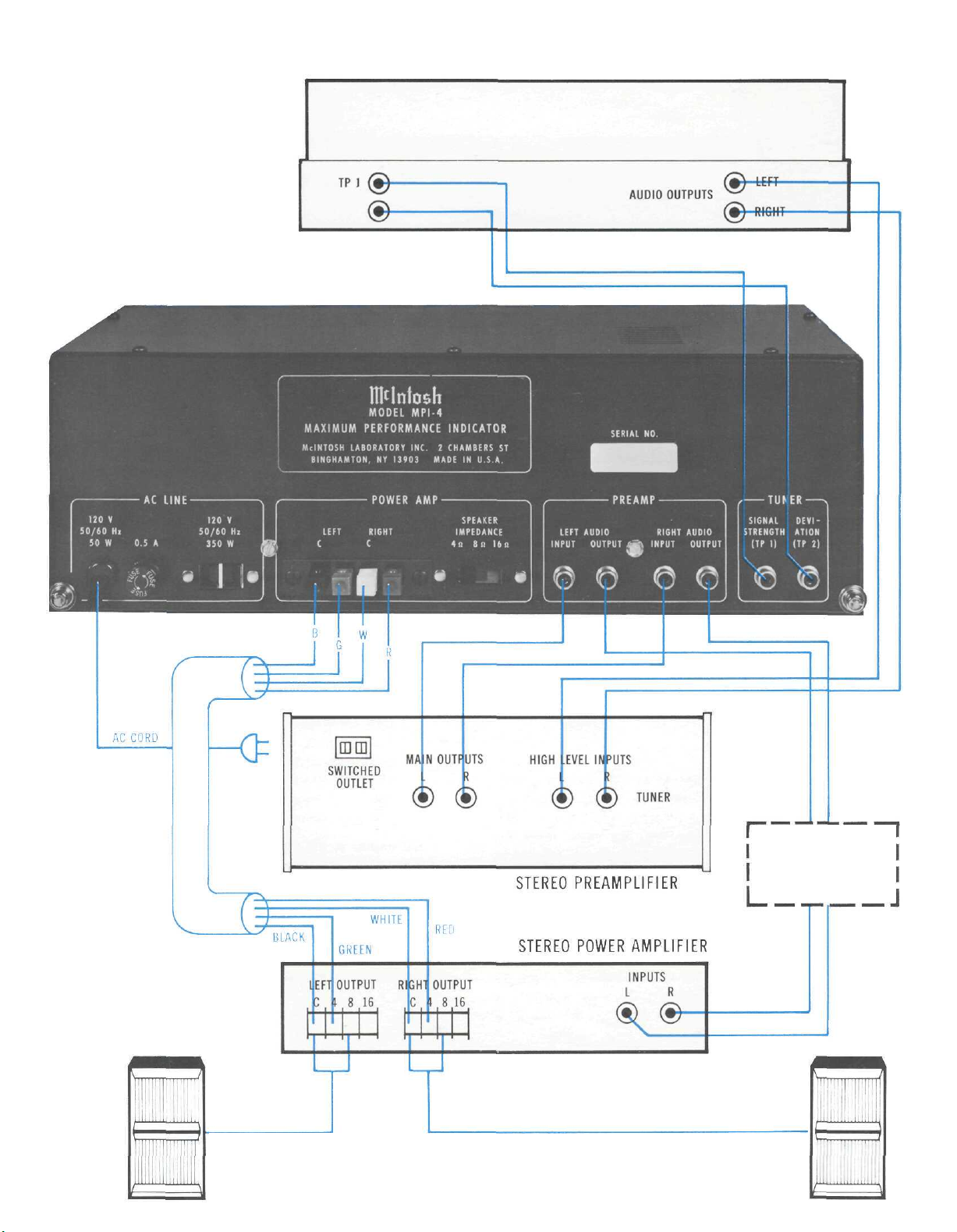
FIG. 2. CONNECTING MPI 4 TO COMPONENT SYSTEM
(TYPICAL CONNECTIONS)
STEREO FM TUNER
LEFT
SPEAKER
ENVIRONMENTAL
EQUALIZER
(OPTIONAL)
RIGHT
SPEAKER
5
Page 8
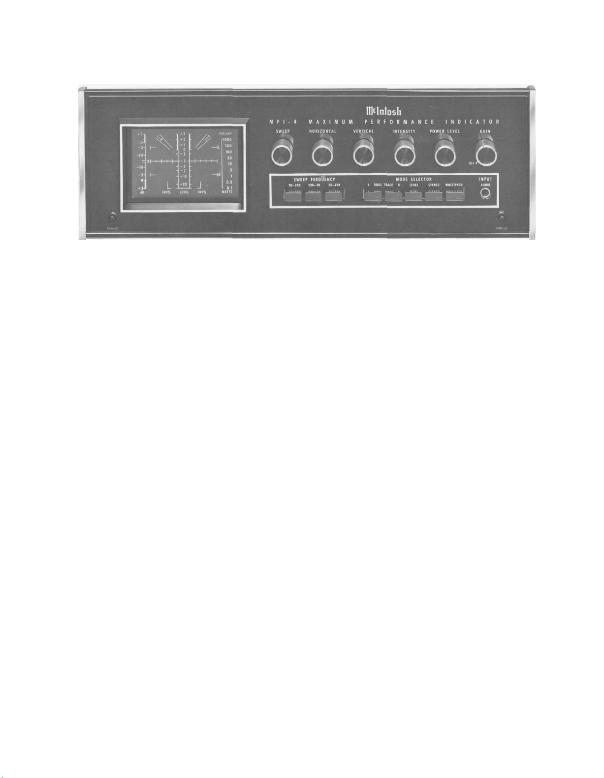
Front Panel information
FIG. 3 FRONT PANEL
MODE SELECTOR
The MODE SELECTOR pushbuttons select the type of
display seen on the screen of the MPI 4. Each of the five
pushbuttons selects a trace—a glowing line of green light—
which shows a variety of information about signals from
the tuner, preamplifier or power amplifier. To assist the
evaluation of each display, the reticle in front of the
screen is marked with calibration points which are used to
measure signal characteristics. As MODE SELECTOR
buttons are pressed, the screen reticle is illuminated in
these colors:
Mode Color
Multipath Blue
Stereo Red
Level Amber
Sweep Green
MULTIPATH
When properly connected to an FM tuner the MPI 4
will detect and display multipart reception. Multipart
reception is the result of a reflected signal arriving at the
tuner antenna slightly later than the direct signal. By
rotating or repositioning the FM antenna it is possible to
reduce multipath reception. The MPI 4 makes it easy to
know when the FM antenna is oriented for the best reception of any station.
To show multipart reception the MPI 4 displays instantaneous signal strength versus frequency deviation.
Signal strength is shown as vertical deflection of the indicator display beam. Frequency deviation is shown as
horizontal deflection. Multipath reception appears as a
peak or valley in the display.
Multipath reception degrades FM tuner performance in
several ways:
1. Usually there is an increase in background noise
level.
2. Distortion is often heard in the program signal
3. Stereo separation may be reduced.
4. The stereo effect may be completely lost.
5. Stereo indicators may fail to function, or function
erratically.
To overcome multipart reception it is usually necessary
to turn the antenna to receive the FM signal by one predominant path. Rotating a directional antenna is effective
at correcting multipath reception. In areas where a simple
antenna such as a dipole is used repositioning the antenna
can achieve similar results.
In the MULTIPATH mode the MPI 4 is a very effective
tuning indicator:
1. Signal strength is shown by the vertical position of
the display trace. The higher the position of the
trace the greater the signal strength.
2. Correct tuning occurs when the display trace is
centered horizontally on the screen. Since the display trace effectively follows the tuner IF response
curve, centering the trace tunes the detector to
the center of the IF curve.
The display of the signal, when there is no multipath
reception affecting the program, appears as a smooth
curving line, (Fig. 4). The calibration points are the two
100% marks at the bottom of the screen. As the program
material grows louder or softer, the trace expands and
contracts. The 100% points indicate the highest modulation percentage normally transmitted by an FM station.
(A more detailed description appears in the "How to Use
Section.")
STEREO
A stereo program causes a complex display which
varies between a circular shape and an elliptical shape.
A mono program causes the display to be a slanted line.
With an in-phase mono program, the signal falls between
the L + R boundaries; in out-of-phase mono program the
trace falls along the L — R boundaries.
6
Page 9

FIG. 4 MULTIPATH DISPLAY
LEVEL
The audio LEVEL of stereo signals is displayed as two
vertical columns on the screen ( Fig. 5). The height of
each column is determined by the power or amplitude of
the input signal. The calibration scale between the two
columns and the position of the POWER LEVEL knob
indicate the actual power of the signal. The nomenclature
on the recticle is shown in decibels (dB).
(20-200 Hz), mid-range frequencies (200-2000 Hz) and
high-range frequencies (2000-20,000 Hz). Use the SWEEP
control for fine tuning of the sweep within any range.
GAIN
The GAIN control operates only when preamplifier
signals are being displayed. The GAIN control varies the
vertical size of the image in all audio modes of operation.
When a signal of unknown strength is to be viewed, start
with the GAIN fully counterclockwise, then turn the control until the display reaches comfortable viewing size.
When the GAIN control is set to OFF, AC power is removed
from the MPI 4.
POWER LEVEL
The POWER LEVEL switch determines the full-scale
calibration in watts of signals displayed on the screen.
When the switch is turned, a red indicator illuminates
the selected power range of the WATTS column along
the right side of the screen ( Fig. 6). These ranges meas-
ure the actual power level of the power amplifier. (How
to use these ranges will be described in the next section.)
When the red indicator is opposite the topmost marking,
PREAMP, the screen displays the amplitude of the pre-
amplifier signal.
FIG. 5 LEVEL DISPLAY OF L & R CHANNEL
DUAL TRACE
When the DUAL TRACE buttons are pressed, the L
(Left) program and the R (Right) programs are seen as
separate traces on the screen. The left channel is the
upper trace; the right channel is the lower.
If only one button under DUAL TRACE is pressed (L
or R), the screen displays only the signal selected.
SWEEP and SWEEP FREQUENCY
Musical program material has many frequencies and it
may be displayed as a complex jumble of waves that are
difficult to view. By changing the timing, or sweep, of the
trace, the MPI 4 can lock onto any portion of the audio
spectrum. The result is a clear, easy-to-view wave that
remains stable on the screen. Use the SWEEP FREQUENCY
pushbuttons to provide a choice of low range frequencies
FIG.
6
INTENSITY
The INTENSITY control adjusts brightness of the trace
on the screen. For longest screen life, use the minimum,
comfortable viewing level.
The trace will disappear when there is no input signal
present. For extended cathode ray tube life a built-in automatic intensity control extinguishes the trace during
non-signal periods to prevent a stationary spot from
burning a permanent mark in the screen surface.
VERTICAL
The VERTICAL control adjusts the up and down location
of the trace on the screen.
HORIZONTAL
The HORIZONTAL control adjusts the left to right loca-
tion of the trace on the screen.
7
Page 10

INPUT AUDIO
TRACE SEPARATION
A microphone, tape recorder, FM tuner or other equip-
ment not normally connected to the rear panel connection of the MPI 4 may be plugged into the INPUT AUDIO
jack on the front panel. Signals are displayed on the screen
for observation or testing. During this time, the POWER
LEVEL selector must be set to the PREAMP position. The
size of the display is adjusted by the GAIN control and
TRIM controls.
Some microphones may not generate enough signal to
drive the display to comfortable viewing levels. This
can be corrected by adding a microphone preamplifier
between the microphone and AUDIO INPUT jack.
Level set Panel
information
AUDIO TRIM LEFT
Adjusts trace height for a left channel preamplifier audio
signal.
AUDIO TRIM RIGHT
Adjusts trace width for stereo display or trace height
for sweep or level display from a right channel preampli-
fier audio signal.
SIGNAL STRENGTH
Adjusts trace height above the bottom or base line of
the multipath display.
DEVIATION
The TRACE SEPARATION control adjusts the distance
between the two traces in the DUAL TRACE mode of
operation.
SWEEP EXPANSION
The SWEEP EXPANSION control adjusts maximum width
of the trace display. SWEEP EXPANSION operates only
when one or both of the DUAL TRACE pushbuttons are
pressed.
TRIGGER SOURCE
The TRIGGER SOURCE switch selects the signal used
to trigger the display sweep. In the DUAL TRACE mode
the sweep may be triggered from the left or right channel,
or from the 60 hertz line frequency.
FOCUS
The FOCUS control adjusts sharpness of the trace.
LOW PASS FILTER
The LOW PASS FILTER switch inserts or removes a filter
that eliminates 19,000 and 38,000 Hz stereo reference
signals. These unwanted signals produce fuzzy and indistinct traces on the screen. The most useful position is
the IN position. Only in special test procedures is it neces-
sary to switch the filter OUT,
RETICLE ILLUMINATION
The RETICLE ILLUMINATION switch turns illumination
of the screen scales on or off.
LEVEL MODE
Adjusts trace width of the multipath display.
MULTIPATH POLARITY
The MULITPATH POLARITY switch controls polarity of
the signal-strength signal. The minus position is used with
most tuners.
In the NORMAL position the two columns rise and fall
like VU meters. In the PEAK position the columns indicate
the "average" peak level for signals that change continuously in amplitude. The Reset position resets the
Peak circuitry and freezes the highest level achieved by
the audio.
FIG. 7 LEVEL SET PANEL
8
Page 11

Rear Panel information
FIG. 8 REAR PANEL
TUNER-SIGNAL STRENGTH (TP 1)
Use the 3 foot low capacity cables provided to connect
Test Point No. 1 (TP 1) on a Mclntosh tuner to this input.
TO PREVENT HIGH FREQUENCY LOSSES, THE SPE-
CIAL 3-FOOT CABLES SUPPLIED MUST BE USED. DO
NOT SUBSTITUTE ORDINARY AUDIO CABLE.
TP 1 supplies the MPI 4 with a voltage which is proportional to the strength of a received FM station. The trace
on the screen will move vertically to indicate relative
signal strength.
TUNER-DEVIATION INPUT (TP 2)
Use the 3 foot low capacity cable provided to connect
Test Point No. 2 (TP 2) on a Mclntosh tuner to this input.
TO PREVENT HIGH FREQUENCY LOSSES, THE SPECIAL 3-FOOT CABLES SUPPLIED MUST BE USED. DO
NOT SUBSTITUTE ORDINARY AUDIO CABLE.
TP 2 supplies a voltage proportional to the modulation
(deviation) of the FM signal. The trace on the screen will
expand in a horizontal direction proportional to a station's
modulation.
PREAMP-LEFT AUDIO INPUT
The left output of a preamplifier connects to this input.
In some modes of MPI 4 operation, the left channel audio
signal causes vertical movement of the trace on the screen.
PREAMP-RIGHT AUDIO OUTPUT
The RIGHT AUDIO OUTPUT jack is directly connected
to the RIGHT AUDIO INPUT jack of the MPI 4. Use the
RIGHT AUDIO OUTPUT jack to connect the preamplifier
output to the right power amplifier input.
POWER AMP-SPEAKER IMPEDANCE
The POWER AMP-SPEAKER IMPEDANCE selector calibrates the MPI 4 to the speaker impedance in use: 4W,
8W or
16W.
POWER AMP CONNECTIONS
The POWER AMPLIFIER push connections are:
Black Left Amplifier Common
Green Left Amplifier High
White Right Amplifier Common
Red Right Amplifier High
AC POWER OUTLET
The AC power outlet may be used to provide AC to
additional equipment drawing up to 350 watts. The outlet
is not fused and is on whenever the MPI 4 power cord is
connected to an AC power outlet.
FUSE
The 0.5 Ampere fuse protects only the MPI 4. It does
not protect additional equipment plugged into the adjacent
AC power outlet. For continued protection replace the fuse
with like value only.
PREAMP-RIGHT AUDIO INPUT
The right output of a preamplifier connects to this input.
In the stereo mode of MPI 4 operation, the right channel
causes the trace on the screen to move horizontally, in
the sweep or level modes the right channel causes the
trace to move vertically.
PREAMP-LEFT AUDIO OUTPUT
The LEFT AUDIO OUTPUT |ack is directly connected
to the LEFT AUDIO INPUT jack of the MPI 4. Use the
LEFT AUDIO OUTPUT jack to connect the preamplifier
output to the left power amplifier input.
Initial Setup
After connecting the MPI 4 as described in the previous
section, turn on all equipment. Release the PANLOC buttons and slide the MPI 4 out to the adjust position. This
allows access to the level set (top panel) controls. Next:
1. Set top panel LEFT AUDIO TRIM and RIGHT AUDIO
TRIM fully counterclockwise, the SIGNAL STRENGTH
and DEVIATION fully counterclockwise, the MULTIPATH POLARITY to minus, the FOCUS control to mid
position, the LOW PASS FILTER to "in", and the
LEVEL MODE switch to NORMAL.
9
Page 12

2. Set front panel GAIN control fully counterclockwise
(but not to Off), the INTENSITY control fully clock-
wise, and the POWER LEVEL switch to PREAMP
(fully clockwise).
3- Depress front panel STEREO pushbutton.
4. Using the front panel HORIZONTAL and VERTICAL
controls, move the spot of light to the center of the
screen, directly behind the 3 in the LEVEL column.
5. Select a mono signal source.
6. Adjust top panel LEFT AUDIO TRIM and RIGHT AUDIO
TRIM to the midpoint in their clockwise travel.
7. Adjust front panel GAIN to obtain a 1- to 2-inch
pattern, and re-adjust both top panel AUDIO TRIM
controls to obtain a pattern similar to Fig. 9.
15. Depress the front panel R button. Determine that the
pattern is similar to that obtained in Fig. 10.
16. Depress both front panel L and R buttons.
17. Adjust top panel TRACE SEPARATION to obtain the
pattern shown in Figure 11.
FIG. 11 DUAL TRACE DISPLAY
18. Depress the front panel LEVEL button.
19. Adjust the front panel POWER LEVEL knob to obtain
the pattern shown in Figure 12.
FIG. 9 STEREO DISPLAY OF A MONO SIGNAL
By adjusting the display within the L + R guide,
the display is balanced for equal amplitude left and
right channels.
8. Adjust intensity control for a comfortable brightness.
9, Adjust top panel FOCUS control for clearest trace.
10- Set the top panel TRIGGER SOURCE switch to LEFT.
11. Depress the front panel L button.
12. Depress the front panel SWEEP FREQUENCY 20-200
button.
13. Adjust the front panel SWEEP control to the approximate midpoint of its range.
14. Adjust the top panel SWEEP EXPANSION control to
obtain the pattern shown in Figure 10. The control
should position near the 1 marking.
FIG. 12 LEVEL DISPLAY OF L & R CHANNEL
20. Depress the front panel MULTIPATH button.
21. Observe that the spot of light is at the bottom center
of the screen.
22. Adjust top panel SIGNAL STRENGTH control to position the spot above the horizontal centerline of the
screen: (If the spot of light moves downward as
the top panel SIGNAL STRENGTH control is adjusted,
set the top panel MULTIPATH POLARITY switch to
its opposite setting.)
23. Adjust the top panel DEVIATION control to obtain
the pattern shown in Figure 13.
FIG. 10 SINGLE TRACE DISPLAY
HOW to use the MPI 4
MULTIPATH MODE
Multipath is caused by an FM signal arriving at your an-
tenna by two (or more) paths, a direct one between an FM
10
Page 13

station and your antenna, and a reflected path which causes
part of the signal to arrive slightly later in time. Such
signals usually degrade stereo reception. Typical multi-
path symptoms include poor channel separation, distortion,
noise or buzzing in the program and erratic operation
of a tuner's stereo indicator.
Multipath free reception is shown in Figure 13. The trace
is formed by a combination of signal strength and modula-
tion (or loudness of the program material). Since signal
strength raises the pattern in a vertical direction, the
higher the trace, the stronger the station. A powerful
local station can be expected to bring the trace to about
½- or ¾-inches below the top of the screen. Weak stations
produce lower heights on the screen.
places the signal at the center of the tuner's IF response
curve, the most desirable point. An example of a detuned
station is shown in Fig. 15: note how the curve is shifted
to the left on the screen. Correct the tuning by adjusting
the tuners tuning knob to center the trace.
FIG. 15 DETUNED STATION
Multipath produces several visible symptons on the
screen. Peaks or valleys may appear on the curve, as shown
in Fig. 16. Note, too, how the entire display is shifted
FIG. 13 MULTIPATH FREE DISPLAY
Program modulation causes the trace to expand in a
horizontal direction. The pattern, therefore, widens in
step with the audio intensity of the program material.
Figure 14 shows a display having multipath. The dips
and peaks are the result of a reflected signal arriving at
the tuner antenna slightly later than the direct signal.
FIG. 14 MULTIPATH INTERFERENCE
By combining displays of strength and modulation,
the MPI 4 will not only show multipath, but is, in addition,
an accurate tuning indicator Adjust the FM tuning dial
until the trace reaches its highest point, while also being
centered horizontally on the screen. Centering the trace
FIG. 16 MULTIPATH & DETUNED
to the left which indicates a combination of both detuning
and multipath reception. In general, a trace that is not
smooth suffers from multipath contamination. In severe
cases, multipath causes considerable fuzziness or blurring
of the overall display.
Multipath is most often overcome by changes in antenna
direction. For outdoor antennas with a rotator, aiming
the antenna in a different direction usually helps. Indoor
dipoles or similar antenna may also be repositioned. In
all cases, best results are clearly indicated on the MPI 4
screen.
Make sure that the MPI 4 is property set up.
1. Turn the POWER LEVEL switch to the PREAMP
position.
2. Set the GAIN control fully counterclockwise (but
not to OFF), and the INTENSITY control fully clockwise.
11
Page 14

3. Depress the STEREO button and check if the spot
of light is in the center of the screen. If not, use
the HORIZONTAL and VERTICAL controls to center
the spot.
To operate the MPI 4 in the MULTIPATH mode:
4. Depress the MULTIPATH button and set the FM
tuner to the desired station. Adjust the INTENSITY
control for desired brightness.
5. Alternately adjust antenna direction and FM
tuning to obtain the highest signal strength and
least multipath, as shown in the illustrations.
STEREO
In this mode, the MPI 4 displays signals sampled from
the preamplifier or power amplifier output. The Left chan-
nel signals cause the trace to deflect in a vertical direction.
Right channel signals extend the trace along a horizontal
line. Randomly phased stereo signals will produce a pattern on the screen appearing like "a ball of twine." (Fig.
23) If left and right signals are present in equal amounts
and equal phase, the display is a diagonal line along the
screen's L + R line (Fig. 17).
This is done by adjusting the left and right gain (or
balance) controls on the preamplifier. If the screen
produces a trace like that of Figure 17, electrical
balance and phase are correct. If the trace is reversed, (Figure 18) the channels are electrically
balanced, but out of phase.
FIG. 18 BALANCED BUT OUT OF PHASE
Consider other possible traces and variations which
may appear during this test. In Figs. 19 and 20 for example, both traces are tilted toward the right which indicates the two channels are correctly in phase. But since
the traces fail to line up with the diagonal screen L + R
calibration they are not equal in electrical strength. In
Fig. 19 the right channel has greater amplitude than the
left channel, and causes the trace to tilt toward the horizontal. In Fig.20, the high vertical tilt of the trace indicates excessive left channel strength. The correct L + R
angle appears when the amplifier gain controls are adjusted for proper balance. Figs. 21 and 22 show the same
effects of electrical unbalance, as well as an out-of-phase
condition.
FIG. 17 IN PHASE & BALANCED
This display also appears when the FM tuner or other
program source is delivering a mono program since right
and left channels are equal.
If only a left channel is present, the trace will extend
only in the vertical direction. If only a right channel is
present the trace will extend only in the horizontal direction. With these indications, you can set the precise balance
of a stereo system.
BALANCE AND PHASE CHECK
Make sure the spot is properly centered (Steps 1, 2
and 3 on pages 11, 12). Then:
1. Depress the STEREO pushbutton.
2. Set the preamplifier or other program source to
deliver a mono signal.
3. Adjust the GAIN control to obtain approximately
a 2-inch display.
4. Balance the program source by making the trace
on the screen fall precisely along the L + R line.
FIG 19
PHASE BUT UNBALANCED
The acoustical balance of the stereo system is affected
by many things including room acoustics, furniture placement, room shape, small differences in loudspeakers, etc.
Electrical balance and acoustical balance may not agree.
12
Page 15

FIG. 20 IN PHASE BUT UNBALANCED
3. Adjust the GAIN control to obtain approximately a
2-inch display.
Stereo separation is usually dictated by the program
source. As you view the screen and listen to a stereo program the pattern may follow several trends. When it extends outward in every direction and approximates a circle,
it is indicating excellent stereo separation between chan-
nels. An example is shown in Fig. 23.
FIG. 23 STEREO DISPLAY
FIG. 21 OUT OF PHASE & UNBALANCED
FIG. 22 OUT OF PHASE AND UNBALANCED
SEPARATION CHECK
A stereo program creates an image on the screen which
vanes between an elliptical and circular pattern. Although
the pattern is irregular and changing, it is possible to
judge the approximate amount of separation between
channels. To make this check make sure the spot is properly
centered, then:
1. Depress the STEREO button.
2. Set the preamplifier or other program source to
the stereo mode.
If the pattern tends toward an elliptical shape, as in
Fig. 24, stereo separation is less than optimum.
FIG. 24 REDUCED SEPARATION
A pattern which tilts toward the left, as in Fig. 25 not
only suggests reduced stereo separation, but indicates an
out-of-phase condition in the program material In judging
any of the patterns just described, allow the program
material to play for enough time for a trend to develop in
the display.
LEVEL MODE
In the LEVEL mode of operation the left channel appears
as a left vertical column on the screen, while the right chan-
nel appears as a right vertical column. Depress the LEVEL
pushbutton and the display should agree with the one
shown in Fig. 26 during a stereo program.
Signals to be viewed are selected by the POWER LEVEL
switch. If the switch is in the PREAMP position, the pre-
L3
Page 16

FIG. 25 OUT OF PHASE
FIG. 26 LEVEL DISPLAY
amplifier outputs are displayed, and their heights can be
adjusted by the GAIN control. For other positions of the
POWER LEVEL selector, the GAIN control is disabled and
power output from the power amplifier is indicated on
the scale in ranges from 100 watts to 0.1 watt. The
level columns respond to the peak voltage present in
the supplied power amplifier signal. The power calibration is in average watts for sine wave signals. Each step
of the POWER LEVEL switch indicates a difference of
5 dB in power output. Turn the POWER LEVEL switch until
you discover a position which completely contains the
peaks of the program material. To convert the display
readings to actual power amplifier output in watts, use the
Power Table, Fig. 31.
Example: Assume the POWER LEVEL control is set so
the red indicator is opposite "10" on the WATTS scale.
While playing program material, assume the trace reaches
a height of "+1" on the LEVEL SCALE (center of the screen).
Consult the POWER TABLE and find "+1" in the LEVEL
SCALE column at left. Next, read to the right until you
reach the "10" column headed under the WATTS heading.
The figure given there is the exact wattage output of the
power amplifier. In this example 6.3 watts.
LEVEL MODE
The top panel LEVEL mode is activated when the MPI-4
LEVEL button is pressed. With the LEVEL mode switch in
the NORMAL position the height of the two columns, as
read on the center dB scale, is an indication of the audio
level. The vertical lines on the screen rise and fall in step
with the program material. The columns rise very quickly,
(250ms rise time) but decay somewhat slowly (½ sec.
decay rate).
With the LEVEL mode switch in the PEAK mode the
two columns indicate the "average" peak value of the
audio waveform. The two columns rise slower (approx.
½ sec.) than in the NORMAL mode and they also fall
slower (25 sec. decay rate). For sound that continuously
changes in amplitude this mode will give an indication
of the "average" peak level. For a sine wave (a continuous
tone) the NORMAL and the PEAK will give the same dB
reading.
The RESET position of the LEVEL mode switch quickly
discharges the "average" Peak timing circuit for making
another "average" Peak measurement.
In some instances, it is desirable to stop the action
and observe the highest point achieved by the audio
signal over a period of time. This permits close comparison between the highest levels attained by left and right
channels and simplifies their measurement against the
scales on the screen. This may be done by placing the
LEVEL MODE switch in the RESET position. This allows
the changing signal to build up and display its highest,
or peak indication. If a higher peak comes along, while
the switch is still held, the two columns will go up to the
higher value. If the power level switch is in a watt position
the two columns will indicate the "equivalent peak average
power" being delivered to the loudspeakers.
The decay time for "Peak" readings while in the RESET
position is 100 seconds. (For a sine wave the peak value
as read in the RESET position will be slightly greater than
in the NORMAL and PEAK positions.)
Return the switch to NORMAL for conventional display.
SWEEP MODE
In the SWEEP mode the MPI 4 operates as a standard
audio oscilloscope. In this mode it is possible to view individual audio cycles in the program. Since most program
material consists of many tones, the MPI 4 may be adjusted to "trigger" at nearly any frequency in the audio
spectrum. This provides a clear display of the range of
interest. If you wish to view tones in the lower end of the
audio range, press the 20-200 pushbutton on the front
panel. Also press the L or R button under the MODE SELEC-
TOR. As the program plays, you should be able to freeze
one or more cycles on the screen by further adjustment
of the SWEEP control (which acts as a fine tuning control).
A single trace display is shown in Fig. 27.
It is also possible to roughly estimate the frequency of
the audio tone displayed on the screen. Assume the SWEEP
FREQUENCY button is set to 20-200 and the SWEEP
control is turned fully counterclockwise. At this time, the
screen is "sweeping" 20 times per second. If one audio
14
Page 17

FIG. 27 SINGLE TRACE SWEEP
cycle appears stationary on the screen, it is a 20 Hz tone.
If 10 cycles appear on the screen at the same settings, the
tone is 200 Hz.
To examine audio tones in the mid-range, press the 2002,000 button. Further adjustment of the SWEEP control
should lock the waveform on the screen. Again, an esti-
mate of frequency may be made. If the SWEEP is set fully
counterclockwise, the trace is sweeping at the rate of
200 Hz. Count the number of cycles on the screen, multiply
by 200, and the result is the audio frequency.
test record jacket and make certain the spot on the MPI 4
is properly centered, then:
1. Depress the STEREO button.
2. Start the phono turntable and set the pickup on the
appropriate test band.
3. Ad|ust the GAIN control to obtain approximately a
2-inch display. Figure 29 shows good compliance and
tracking, while Figure 30 shows distortion due to
improper tracking.
FIG. 29 GOOD TRACKING
Tones in the highest range are observed with the SWEEP
FREQUENCY button in the 2,000-20,000 band. If the
SWEEP control is set fully counterclockwise, (a 2000 Hz
sweep), two cycles on the screen represent a 4000 Hz
tone; three cycles are a 6000 Hz tone, etc.
The screen can simultaneously display left and right
stereo channels as a dual trace, as shown in Fig. 28. To
view both signals, depress L and R pushbuttons of the
DUAL TRACE MODE SELECTOR.
FIG. 28 DUAL TRACE DISPLAY
It is possible to magnify the display for closer viewing by
adjusting the SWEEP EXPANSION control on the top panel
as desired.
PHONO PICKUP COMPLIANCE AND TRACKING CHECK
With the aid of a test record, compliance and tracking of
a pickup may be checked. Follow the instructions on the
FIG. 30 IMPROPER TRACKING
FREQUENCY RESPONSE CHECK
Check the frequency response of your system with the aid
of a test record. The graph in Fig. 31 shows an ideal RIAA
curve using the CBS STR 100 test record. Make this test
and all single frequency tests at low acoustic levels to
prevent potential loudspeaker damage. To perform a
frequency response check:
1. Play the 1000 Hz test tone on the phonograph.
2. Adjust the preamplifier volume control for an adequate sound level. Be cautious. The use of loud single
frequency program material can overload loudspeaker
systems.
3. Set the POWER LEVEL selector to a setting which provides column heights closest to the 0 dB mark on the
level scale.
4. Adjust your preamplifier volume controls to obtain
precise 0 dB readings for both columns using the
15
Page 18

1000 Hz test tone.
5. Play the other tones on the test record and write
down the column indications for each frequency
played on the test record.
6. Transfer the readings obtained in Step 5 to the
graph in Figure 33. Compare your curve with the
curve on the graph. A deviation of 3 dB is acceptable.
increase the level of the right volume if necessary.
Each step of the POWER LEVEL switch adds 5 dB.
(20 dB is generally considered fair, 30 dB good and
40 dB excellent.
Repeat steps 2, 3 and 4 but play the right channel for
right to left channel separation measurements.
LEVEL
SCALE
(dB)
-10
-20
PHONO CHANNEL SEPARATION CHECK
Check channel separation of your system with the aid
of a test record (such as the CBS STR 100).
Make this test and all single frequency tests at low
acoustic levels to prevent potential loudspeaker damage.
To observe the results follow the instructions furnished
with the test record and:
1. Depress the LEVEL button.
2. Play the left channel spot frequency band on the
3. Set the POWER LEVEL selector to a position that
4. You should obtain a display like that shown in Figure
POWER LEVEL SWITCH SETTING (WATTS)
1000
300
100
30
10
+3
1000
300
100
+2
800
240
80
+1
630
190
63
0
500
150
-1
-3
-5
-7
312
250
126
100
50
5
record.
yields approximately 0 dB deflection on the left
column.
32. The difference in height between left column and
right column indicates left to right channel separation
in dB. The POWER LEVEL switch may be advanced to
50
93
31.2
75
25
38
12.6
30
10
15
5
1.5
0.5
FIG. 31 POWER TABLE
30
24
19
15
9.3
7.5
3.8
3.0
1.5
.15
10
8
6.3
5
3.12
2.5
1.26
1.0
.5
.05
2.4
1.9
1.5
.93
.75
.38
.15
.015
.3
3
1
3
3
1.0
.3
.8
.24
.08
.63
.19
.063
.5
.15
.05
.312
.093
0312
.25
.075
.025
.126
.038
0126
.1
.05
.005
.01
.030
.015
.005
.0005
.0015
.1
.1
FIG. 32 CHANNEL SEPARATION (Approx 15dB)
AMPLIFIER LINEARITY CHECK
With the aid of a test record you may perform an ampli-
fier linearity check.
Make this test and all single frequency tests at low
acoustic levels to prevent potential loudspeaker damage.
High intensity single frequency program material can
overheat the loudspeakers voice coil and cause burn out.
To perform this check:
1. Depress the L button.
2. Play the 1000 Hz test tone on the record.
3. Set the POWER LEVEL selector switch to a setting that
produces an adequate display between 1000 and 0.1
watt.
4. Depress the 200-2,000 SWEEP FREQUENCY button
and adjust the SWEEP control to obtain a few cycle
waveform.
5. Referring to Figure 34: waveform A is sinusoidal and
16
Page 19

IDEAL RIAA SYSTEM RESPONSE USING CBS STR 100 TEST RECORD
4
2
0
-2
-4
6
-8
-10
-12
-14
-16
20
I 00
1,000
10,000
-18
-20
20,000
4
2
0
2
4
-6
-8
10
20
FREQUENCY IN Hz
100
FIG. 33
1,000
12
-14
-16
-18
20
20,00010,000
17
Page 20

indicates the amplifier has low or little distortion:
waveform B indicates poor linearity and clipping:
while waveform C indicates crossover distortion.
6. Depress button R and observe the right channel
waveform.
Performance Limits
All ratings are nominal
MULTIPATH MODE OF OPERATION
Sensitivity: l00mV/cm
Frequency Response: DC to 50kHz (-3dB)
Input Impedance: 250,000 W
Signal Strength Polarity: Selectable positive or negative
STEREO MODE OF OPERATION
Sensitivity - L (Vertical Amp.): 1.75mV rms/cm (5mV
P-P/cm)
Sensitivity - R (Horizontal Amp.): 1 75mV rms/cm (5mV
P-P/cm)
Frequency Response: 5Hz to 50kHz (-3dB)
Input Impedance: 250,000W
FIG. 34 (a) NORMAL
(b) CLIPPING
POWER LEVEL MODE OF OPERATION
Sensitivity
Frequency Response: 5Hz to 100kHz ( -3dB)
Input Impedance: 75,000 W
Calibration: For bridging 4,8 or 16 ohm speaker loads
PREAMP LEVEL MODE OF OPERATION
Sensitivity: 15mV rms for +3dB indication
Frequency Response: 5Hz to 50kHz
Input Impedance: 250,000 W
SWEEP MODE OF OPERATION
Display modes: Left, right, or both (dual trace)
Sensitivity: 1.6mV rms/cm (4 5mV P-P/cm)
Frequency Response: 5Hz to 50kHz ( - 3dB)
Input Impedance. 250,000 W
Sweep Frequency: 20Hz to 20,000 Hz in 3 Decade
ranges
Sweep Expansion: 0.25X to 5X
Sweep I rigger: The sweep is triggered only in the pres-
0.1 to
indication (+3dB) in 9 calibrated steps.
1000
average
ence of an input signal.
In the single trace mode it is triggered
by the displayed waveform.
watts
for
lull
scale
(c) CROSS OVER DISTORTION
In the dual trace mode the trigger is
selectable: left channel, right channel,
or line frequency.
LEVEL INDICATION MODE
Normal 250 m s rise time
500ms fall time
Peak: 500ms rise time
25sec fall time
Reset. 250 m s rise time
l00sec fall time
18
Page 21

LOW PASS FILTER
16,000 Hz L.F. Filter for stereo and sweep modes.
Technical Description
19,000 Hz and 38,000 Hz rejected by at least 30dB
RETICLE LIGHTING
Selectable: On-Off
CRT
3 inch round tube, calibrated 5 x 6cm
1,000 Volt accelerating potential
Automatic Intensity Control: In the absence of a hori-
zontal signal, the intensity is reduced to prevent
phosphor damage.
SEMICONDUCTOR COMPLEMENT:
2 integrated circuits
23 Transistors
10 Light emitting diodes
29 Diodes
POWER SUPPLES
All are regulated to give equivalent performance tor line
voltages of 100 to 135 volts.
POWER REQUIREMENTS: 120 volts 50/60Hz 50 watts
SIZE:
Front panel measures 16 inches wide (40.65 cm) by
5-7/16 inches high (13.8 cm). Chassis measures 15
inches wide (38.1 cm) by 5 inches high (12.7 cm) by
13 inches deep (33.1 cm) including PANLOC mounting
brackets and back panel connectors. Knob clearance
required is 1½ inches (3.85 cm) in front of the mounting panel.
FINISH:
Front panel is anodized gold and black with special
gold/teal nomenclature illumination. Chassis is black.
MOUNTING:
Exclusive Mclntosh developed professional PANLOC.
WEIGHT:
21 pounds (9.55 kg) net, 33 poinds (15 kg) in shipping
carton.
INPUT SWITCHING AND DISPLAY
The MPI 4 has four inputs: tuner, preamplifier, power
amplifier and front panel jack. The first three are perma-
nently connected to the MPI 4, while the front panel jack
provides the flexibility to observe additional signals.
Tuner signals are connected directly to the MODE
SELECTOR-MULTIPATH pushbutton. The preamplifier,
front panel jack and power amplifier signals are routed
to the POWER LEVEL selector switch and then to the
MODE SELECTOR pushbuttons. By setting the POWER
LEVEL switch to PREAMP, preamplifier signals are selected
for display. Whenever a plug is inserted into the front
panel jack, the preamplifier connections at the rear of the
MPI 4 are disconnected and the front panel jack signals
are displayed instead. By setting the POWER LEVEL switch
to a position other than PREAMP, power amplifier signals
are displayed.
SIGNAL PROCESSING
Preamplifier signals and front panel signals are applied
through LEFT and RIGHT AUDIO TRIM controls, the GAIN
control and the POWER LEVEL switch to left and right
preamplifiers. Power amplifier signals are routed through
the IMPEDANCE MATCHING NETWORK, POWER LEVEL
ATTENUATOR selector and POWER LEVEL switch to left
and right signal amplifier.
Each of the signal amplifiers comprises one-half of
a dual high-gain operational amplifier operating in a
non-inverting mode. These amplifiers amplify the input
signals to the level necessary to drive the peak detectors.
Each peak detector consists of a diode and a capacitor
which stores the peak level of the audio signal. Decay
time is controlled by a resistor selected by the LEVEL
MODE switch with Normal, Peak and Reset positions. The
outputs of the signal amplifiers are also applied to a
trigger source switch and the MODE SELECTOR switch.
The MODE SELECTOR switch routes tuner, preamplifier
and peak detector output signals as follows:
1. In the MULTIPATH mode signal strength and deviation signals are applied to vertical and horizontal amplifiers, respectively.
2. In the STEREO mode left and right preamplifier
signals are applied to the vertical and horizontal amplifiers.
3. In the LEVEL mode peak detector outputs are applied
to a switching amplifier.
4. In the DUAL TRACE and SINGLE TRACE mode preamplifier signals are applied to a switching amplifier after
going through or around the LOW PASS FILTER. The
filter removes 19,000 and 38,000 Hz signals which interfere with the display.
The switching amplifier is a unity gain DC amplifier
which alternately selects left and right channels. In the dual
19
Page 22

FIG. 34 LOW PASS FILTER RESPONSE
trace mode the right channel is offset from the left channel
by an amount determined by the TRACE SEPARATION
control. In the single trace mode the switching amplifier
passes the desired channel (left or right) to the vertical
amplifier.
Vertical and horizontal amplifiers are identical wide band
DC coupled amplifiers. Each consists of two cascaded
differential pairs. The input pair is a Darlington configura-
tion for high input impedance. The second pair comprises
high-voltage transistors that drive the deflection plates
of the cathode ray tube.
AUTOMATIC INTENSITY CONTROL
An automatic intensity control circuit is connected to
the output of the horizontal amplifier and senses the AC
component of the horizontal output. The circuit works with
the INTENSITY control; when modulation is not present
intensity is reduced to avoid burning the phosphor on the
face of the cathode ray tube. At all but full intensity settings the spot is extinguished. At full intensity the spot
does not extinguish so it may be located and adjusted for
position on the screen.
The linear ramp is fed into an emitter follower which
provides the time base output and also drives a differential
pair. The amplitude of the time base output is controlled
by the SWEEP EXPANSION. The differential pair senses
when the ramp has reached a certain voltage level. In
single and dual trace modes this level is a fixed voltage
and it determines when the sweep terminates. In the level
mode this voltage corresponds to alternate outputs from
the two peak detectors and determines the height of the
two columns. When this voltage is reached, the differential
pair generates a trigger hold-off pulse long enough to
discharge the capacitor in the R-C network. During the
hold-off period the sweep cannot be restarted and the
cathode ray tube is blanked.
The hold-off pulse feeds one-half of a dual type D flipflop and sets the flip-flop. When the hold-off pulse terminates, the flip-flop allows the capacitor to charge again
after it receives a signal from the trigger amplifier. The
other half of the flip-flop switches each time the ramp
terminates the sweep. This half generates a square wave
signal that drives the Left-Right switching amplifier. During
the LEVEL mode the square wave alternates the column
position to the left and right for a two column display.
POWER SUPPLIES
There are five power supplies in the MPI 4: -5 volts;
+ and -- 15 volts; 200 volts; and -1000 volts. Each is
regulated to assure that the calibrated display does not
change due to line voltage variations.
The - 5 and - 15 volt supplies are derived from a full-
wave rectifier and are regulated by zener diodes. The 200
volt supply is derived from a half-wave rectifier and is
regulated by an active voltage regulator. The -1000
volts supply, which provides cathode ray tube anode
acceleration voltage, is obtained from a zener-regulated
voltage doubler.
TRIGGER AMPLIFIER
The trigger amplifier operates in single and dual trace
modes. Depending on the TRIGGER SOURCE switch setting, it uses left or right preamplifier outputs, or line
frequency signals, to provide a steady presentation of small
vertical deflection signals on the cathode ray tube. The
trigger amplifier is a two-transistor high gain amplifier
whose output voltage is compatible with the digital IC
in the sweep generator.
SWEEP GENERATOR
When the sweep is triggered a linear ramp is generated
by an R-C network consisting of a high-voltage source
charging a capacitor through a high-value resistor. The
resistor value is set by the SWEEP control, while the capacitor value is selected by SWEEP FREQUENCY push-buttons.
The high-value resistor and high voltage effectively serve
as a current source.
20
Page 23

Block Diagram
Page 24

038-439
MclNTOSH LABORATORY INC.
2 CHAMBERS ST., BINGHAMTON, N. Y. 13903
607-723-3512
Design subject to change without notice.
Printed in U.S.A.
 Loading...