

Page 1
McIntosh Laboratory, Inc. 2 Chambers Street Binghamton, New York 13903-2699 Phone: 607-723-3512 www.mcintoshlabs.com
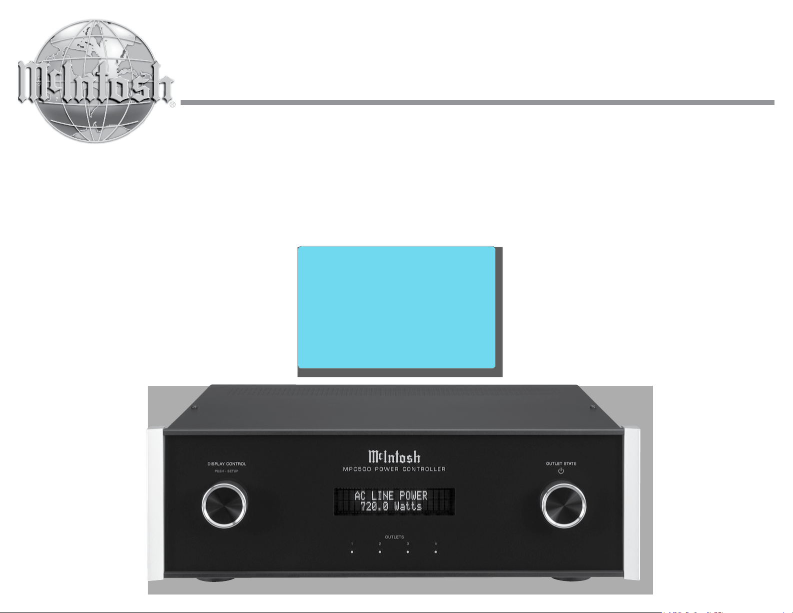
MPC500
Power Controller
Owner’s Manual
Page 2

Important Safety Information is supplied in a separate document “Important Additional Operation Information Guide”
Thank You
Your decision to own this McIntosh MPC500 Power
Controller ranks you at the very top among discriminating music listeners with the desire to protect your
audio components. You now have “The Best.” The
McIntosh dedication to “Quality,” is assurance that
you will receive many years of enjoyment from this
unit.
Please take time to read the information in this manual. We want you to be as familiar as possible with all
the features and functions of your new McIntosh.
Please Take A Moment
The serial number, purchase date and McIntosh Dealer
name are important to you for possible insurance
claim or future service. The spaces below have been
provided for you to record that information:
Serial Number: _______________________________
Purchase Date: _______________________________
Dealer Name: ________________________________
Technical Assistance
If at any time you have questions about your McIntosh products, contact your McIntosh Dealer who is
familiar with your McIntosh equipment and any other
brands that may be part of your system. If you or your
Dealer need additional help concerning a suspected
problem, you can receive technical assistance for all
McIntosh products at:
McIntosh Laboratory, Inc.
2 Chambers Street
Binghamton, New York 13903
Phone: 607-723-3512
Fax: 607-724-0549
Customer Service
If it is determined that your McIntosh product is in
need of repair, you can return it to your Dealer. You
can also return it to the McIntosh Laboratory Service
Department. For assistance on factory repair return
procedure, contact the McIntosh Service Department
at:
McIntosh Laboratory, Inc.
2 Chambers Street
Binghamton, New York 13903
Phone: 607-723-3515
Fax: 607-723-1917
Table of Contents
Safety Instructions ..................................................... 2
(Separate Sheet) ................... Important Additional
Operation Information Guide
Thank You and Please Take a Moment ....................... 2
Technical Assistance and Customer Service .............. 2
Table of Contents ........................................................ 2
General Information ................................................... 2
Connector and Cable Information ..............................3
Introduction .................................................................3
Performance Features ................................................. 4
Dimensions .................................................................5
Installation ..................................................................6
Rear Panel Connections (100V-120V) ........................7
How to Connect for 100V-120V .................................. 8
Rear Panel Connections (220V-240V) ........................ 9
How to Connect for 220V-240V ...............................10
Front Panel Displays and Controls ............................ 12
How to Operate .................................................... 13 -15
Photos ................................................................... 16-17
Specifications ............................................................ 18
Packing Instruction ................................................... 19
Copyright 2019 © by McIntosh Laboratory, Inc.
General Information
1. For additional connection information, refer to the
Owner’s Manual(s) for component(s) connected to
the MPC500.
2. McIntosh MPC500 Products are marketed world
wide. There are two different versions of the
MPC500 Components. Each of the different versions of MPC500 have different AC Outlet Connectors and operate with either 100Volts to 120Volts
or 220Volts to 240Volts. This MPC500 Owner’s
Manual contains information about both versions
of the MPC500 to meet the different AC Power and
Safety Requirements for use in your country.
3. The Main AC Power going to the MPC500 and any
other McIntosh Component(s) should not be applied
until all the system components are connected
together. Failure to do so could result in malfunctioning of some or all of the system’s normal operations.
4. The MPC500 is designed for connection with Audio/Video Components. This would include components such as Preamplifiers, A/V Control Centers,
Source Components, Integrated Amplifiers and
Power Amplifiers with low to modest power output.
5. The total amount of current drawn by all the
components connected to the MPC500 should not
exceed the Current Amperage Rating indicated on
the rear panel of your MPC500. Typically, components consuming low amounts of energy are rated
in wattage instead of current. Refer to the MPC500
Versions chart on the next page for converting a
wattage rating into an approximate current rating.
6. Caution: Verify the protective earthing connection
of socket-outlet for the plug of AC input
power cord by a Skilled person.
2
Page 3
Connector and Cable Information
Pin 1
Pin 1
Pin 8
MPC500 Versions
120VAC 230VAC
Watts Rating
on component
0- 50 Watts
51-100 Watts
101-150 Watts
151-200 Watts
201-250 Watts
Approximate
current
0.5A 0.25A
1A 0.5A
1.5A 0.75A
2A 1A
2.5A 1.25A
Approximate
current
7. For additional information on the MPC500 and
other McIntosh Products please visit the McIntosh
Website at www.mcintoshlabs.com.
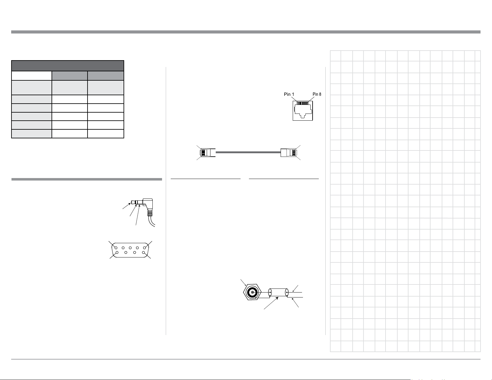
Connector and Cable Information
RS232 Data Port Cable
The RS232 Data Cable has 3.5mm stereo mini
phone plug at both ends of the
cable. Some Source Component
Products use a sub miniature
DB9 Connector on their rear
panels. Therefore, connecting
from those Source Components
requires an adaptor cable with a
3.5mm Stereo Mini Phone Plug
on one end to a DB9 Connector
on the other end of the cable.
Those type of cables are available from various retail
stores that sell Computer Cables.
PIN 1
PIN 6
Data In
(DB9-pin2)
Data Out
(DB9-pin3)
Ground
(DB9-pin5)
DB9
(male connector)
PIN 5
PIN 9
following information includes the eight pin connector
Socket and the Ethernet Connection Cable.
Ethernet RJ45 Socket
1. Transmit Data (+) 5. N/C
2. Transmit Data (-) 6. Receive Data (-)
3. Receive Data (+) 7. N/C
4. N/C 8. N/C
Ethernet Cable - Straight Thru Connections
Pin 8
Pin Number - Wire Color Pin Number - Wire Color
1. Orange/White → 1. Orange/White
2. Orange → 2. Orange
3. Green/White → 3. Green/White
4. Blue → 4. Blue
5. Blue/White → 5. Blue/White
6. Green → 6. Green
7. Brown/White → 7. Brown/White
8. Brown → 8. Brown
Antenna “F” Connector
ANTenna IN, connects to the Cable Company Signal.
The ANTenna OUT, connects to a FM Tuner Connector.
“F” Connector
Data Signal
Ethernet Network Cable
The Ethernet Data Cable is for the connection of Data
Signal from an Outside Data Network Source to various Audio/Video System Components. The Ethernet
RJ45 Socket has eight electrical connections of which
includes Receiving Data and Transmitting Data. The
Coaxial
Shielded
Cable
Ground
3
Page 4
Introduction
The McIntosh MPC500 Power Controller provides a
High Degree of Continuous Surge Protection to the
Audio/Video Components that are connected to the
MPC500 while performing their operational functions.
Performance Features
• Illuminated Multifunction Display
The comprehensive On-Screen Display makes it easy
to perform setup. The Front Panel display indicates
Voltage and Current at all times of connected McIntosh Components along with other operating functions.
• AC Line Surge Protection & EMI Filtering
The McIntosh MPC500 utilizes the finest, most
sophisticated surge suppression technology available.
It incorporates TPMOVs that are thermally protected
from abnormal overvoltage occurrences and have
four times the surge capability of the common MOVs
(Metal Oxide Varistor) devices used by other companies. The MPC500 also offers EMI Filtering from the
AC Line source for the components connected to it.
nected components by continuously monitoring the
input voltage and then switching off the rear outlets
during a fault.
• Power Control Assignment
The Power Control input connection provides convenient switching ON/OFF of any connected components by removing/connecting the power from the
desired outlet. All the Power Control ports are individually configured allowing for extreme customization.
• Power Control
The Power Control Input connection provides convenient Turn-On/Off of the McIntosh MPC500 with your
McIntosh System.
• Glass Front Panel and Super Mirror Chassis
Finish
The famous McIntosh Illuminated Glass Front Panel
uses long life Light Emitting Diodes (LEDs) and
the Steel Chassis ensures the pristine beauty of the
MPC500 will be retained for many years.
• Low Voltage DC Surge Protection
The McIntosh MPC500 utilizes GDT (Gas Discharge
Tubes), PTC (Positive Temperature Coefficient
thermistors) and TVS (Transient Voltage Suppression)
components to protect your low voltage devices. This
cascade approach provides a lower clamping voltage
with increased surge capability.
• Over/Under Voltage Protection
The McIntosh MPC500 Over/Under Voltage Protection circuitry prevents possible damage to your con-
4
Page 5
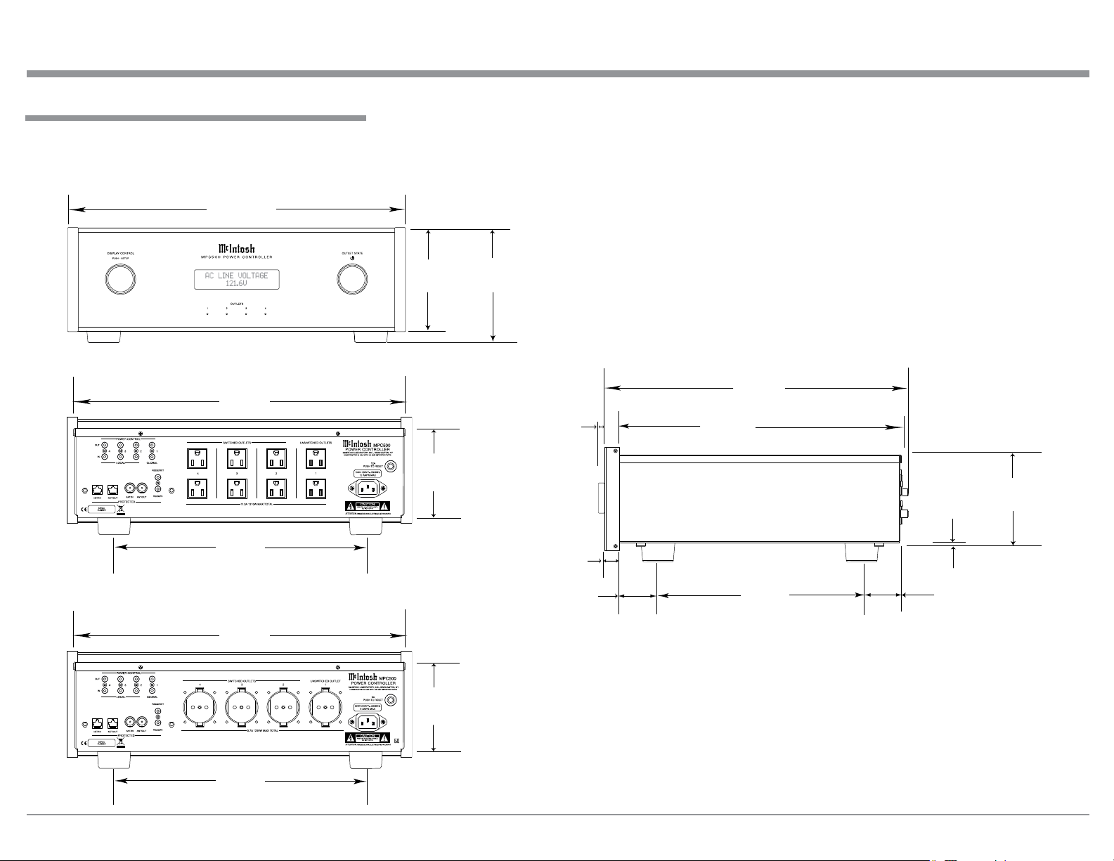
Dimensions
The following dimensions can assist in determining
the best location for your MPC500.
Front View of the MPC500
17-1/2"
44.5cm
Dimensions
Rear View of the MPC500 (100V-120V)
17-1/8"
43.5cm
13-1/4"
33.7cm
Rear View of the MPC500 (220V-240V)
17-1/8"
43.5cm
5-3/8"
13.7cm
4-5/8"
11.8cm
6"
15.2cm
5/8"
1.6cm
13/16"
2.1cm
2"
5.1cm
Side View of the MPC500
15-3/4"
40cm
14-5/8"
37.1cm
10-9/16"
26.8cm
3/16"
0.5cm
1-15/16"
4.9cm
4-13/16"
12.2cm
13-1/4"
33.7cm
4-5/8"
11.8cm
5
Page 6
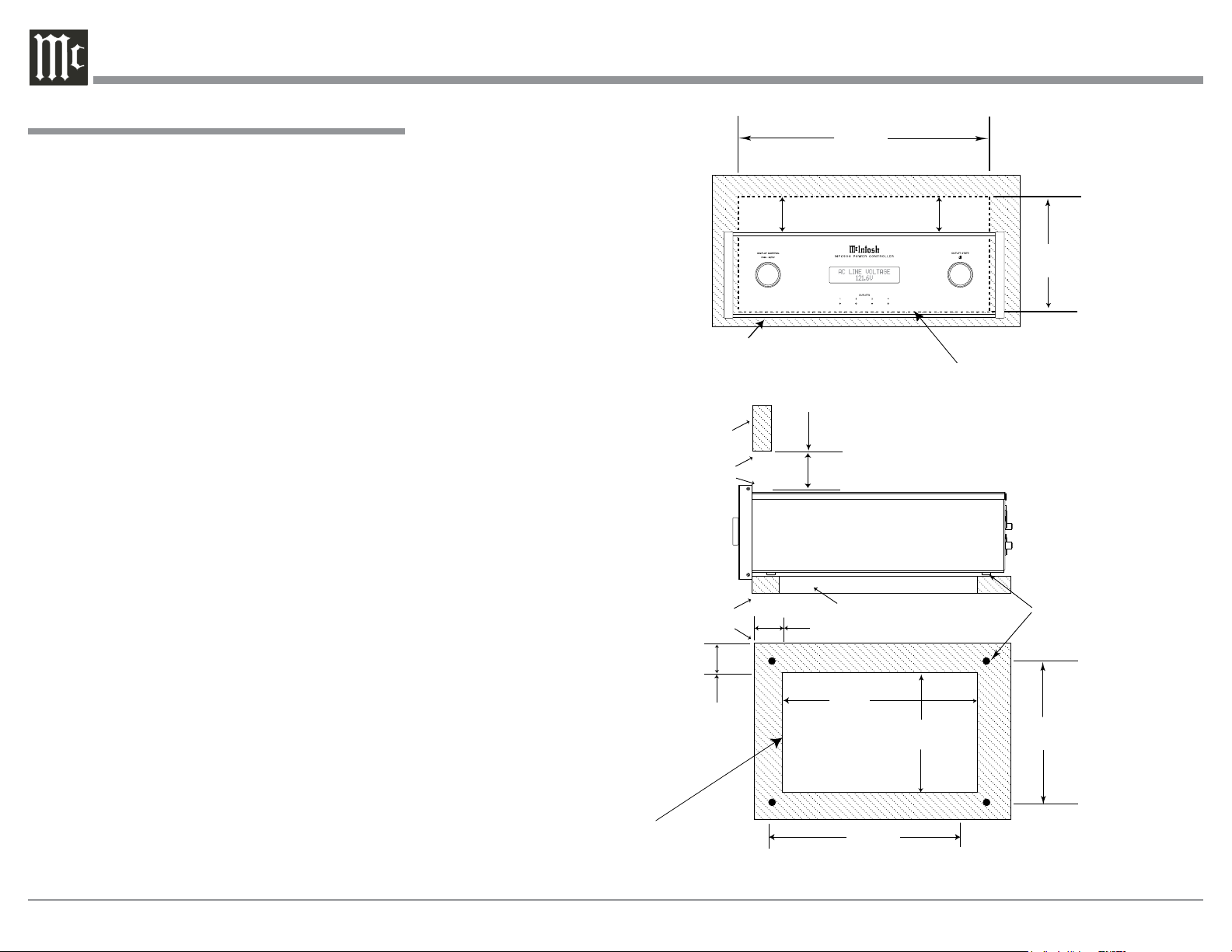
Installation
Installation
The MPC500 can be placed upright on a table or
shelf, standing on its four feet. It also can be custom
installed in a piece of furniture or cabinet of your
choice. The four feet may be removed from the bottom
of the MPC500 when it is custom installed as outlined below. The four feet together with the mounting
screws should be retained for possible future use if the
MPC500 is removed from the custom installation and
used free standing. The required panel cutout, ventilation cutout and unit dimensions are shown.
Always provide adequate ventilation for your
MPC500. Cool operation ensures the longest possible
operating life for any electronic instrument. Do not
install the MPC500 directly above a heat generating component such as a high powered amplifier. If
all the components are installed in a single cabinet, a
quiet running ventilation fan can be a definite asset in
maintaining all the system components at the coolest
possible operating temperature.
A custom cabinet installation should provide the following minimum spacing dimensions for cool operation.
Allow at least 2 inches (5.08cm) above the top, 2
inches (5.08cm) below the bottom, 3 inches (7.62cm)
behind the rear panel and 2 inches (5.08cm) on each
side of the Power Controller, so that airflow is not
obstructed. Allow 7/8 inch (2.22cm) in front of the
mounting
ventilation hole in the mounting shelf according to
the dimensions in the drawing.
1
When the MPC500 is installed together with other Mc-
Intosh Components, check clearances on all components
before proceeding.
1
panel for clearance. Be sure to cut out a
MPC500 Front Panel
Custom Cabinet Cutout
MPC500 Side View
in Custom Cabinet
MPC500 Bottom View
in Custom Cabinet
Note: Center the cutout Horizontally
on the unit. For purposes of
clarity, the above illustration
is not drawn to scale.
Cabinet Front Panel
Cabinet
Front
Panel
Opening
for Ventilation
Support
Shelf
2"
5.08cm
17-1/16"
43.34cm
Opening for Ventilation
Cutout Opening for Custom Mounting
2"
5.08cm
Cutout Opening for Ventilation
1-5/8"
4.13cm
10"
25.4cm
Cutout
Opening
for
Ventilation
13-11/16"
34.77cm
15"
38.1cm
7-3/8"
18.78cm
Chassis
Spacers
15"
38.1cm
6
Page 7

7
Page 8

Rear Panel Connections MPC500 (100V-120V)
POWER CONTROL OUTputs send turn On/Off
Signals to a connected McIntosh Component.
POWER CONTROL INputs receive turn On/Off
signals from a McIntosh Component
SWITCHED AC OUTLETS (2-4) are controlled by MPC500 POWER CONTROL
Settings and/or the received Power Control
Signal from other components
UNSWITCHED AC OUTLETS (1) become
active when the MPC500 AC POWER CORD is
connected to an active external AC Outlet
CIRCUIT BREAKER
PRESS TO RESET if the
MPC500 Power Controller
will not power up
NETwork/IN provides protection for input Data
Signal from Outside Data Network Source.
NETwork/OUT provides the protected Data
Signal from the Network Input for connection to
Audio/Video Components
ANTenna/IN provides protection for the FM RF
Signal from Outside FM Network Source.
ANTenna/OUT provides the protected FM RF Signal
for connection to Audio/Video Tuner Components
8
RS232/IN provides protection for the Serial Data Input Signal
from a RS232 Output from another connected Audio/Video
Component.
RS232/OUT provides a protected Serial Data Output Signal
to be connected to other Audio/Video Components
Connect the MPC500 power cord
to a live AC outlet. Refer to information on the back panel of your
MPC500 to determine the correct
voltage for your unit
Page 9

How to Connect MPC500 for (100V-120V)
Caution: Do not connect the AC Power Cord to the
MPC500 Rear Panel until after the Audio/
Video Components have been Connected to the
MPC500.
The connection instructions below, together with the
MPC500 Connection Diagram located on the separate folded sheet “Mc1A”, are an example of a typical
Audio/Video System. The MPC500 has the ability
to automatically switch AC Power On/Off to Components connected to the MPC500 SWITCHED AC
OUTLETS (2 thru 4) via the Power Control Connection (1 thru 4). Your system may vary from this,
however the actual components would be connected in
a similar manner. For additional information refer to
“Connector and Cable Information” on page 3.
Power Control Connections:
1. Connect a Control Cable from the A/V Control
Center TRIGger (Power Control) 1 Jack to the
POWER CONTROL INput 2 Jack on the MPC500
for primary listening.
2. Connect a Control Cable from the MPC500
POWER CONTROL OUTput 2 Jack to the Media
Bridge PWR CTRL (Power Control) IN Jack.
3. Connect a Control Cable from the Media Bridge
PWR CTRL (Power Control) OUT Jack to the
AM/FM Tuner Power Control IN Jack.
Network Connections:
Use CAT 5/6 Ethernet Type Cables to provide con-
nections between the MPC500 and all the Network
Connectors on the Audio/Video Components along
with Network Router/Switch and Ethernet Crossover
Adapter.
4. Connect a Ethernet Cable from the Cable Company Connection unit Net Output Connector, to the
MPC500 NET/IN Connector.
5. Connect a Ethernet Cable from the MPC500 NET/
OUT Connector to the Network Router/Switch and
Ethernet Crossover Adapter Input Connector.
6. Connect Network Cables from the Router/Switch
or Ethernet Crossover Adapter NETWORK Output
connectors to each of the Audio/Video Components (A/V Control Center, Media Bridge, and any
addition components) with NETWORK Connectors.
RS232 Connections:
Use either type of RS232 Cables to make the neces-
sary RS232 Connections. Either a 3.5mm stereo mini
phone plug RS232 Cable on both cable ends or when
necessary, a cable with Sub Miniature DB9 Connector
on one end and a 3.5mm stereo mini phone plug on
the other end.
7. Connect the appropriate RS232 Cable from the
A/V Control Center RS232 Connector to MPC500
RS232/IN Connector.
8. Connect the appropriate RS232 Cable from the
MPC500 RS232/OUT Connector to the AM/FM
Tuner RS232 Connector.
Antenna Connections:
Use a RF Cable with “F” Connectors for providing
FM Radio Frequency (or Video) Transmitted Signal
between components.
9. Connect a RF Cable from the Cable Company
Connection unit to the MPC500 ANT/IN Input
Connector.
10. Connect the MPC500 ANT/OUT Connector via
a RF Cable with “F” Connectors to the AM/FM
Tuner FM ANT Connector.
Switched AC Power Outlets:
Use the AC Power Cords that were supplied with each
of the Audio/Video Components in the following
steps:
How to Connect MPC500 for (100V-120V)
11. Connect an AC Power Cord from the A/V Control
Center to the MPC500 UNSWITCHED Upper
Outlet Number 1.
12. Connect an AC Power Cord from the Media
Bridge External Power Supply to the MPC500
Switched Upper Outlet Number 2.
13. Connect an AC Power Cord from the AM/FM
Tuner to the MPC500 Switched Lower Outlet
Number 2.
14. Optionally, connect additional Audio/Video Components AC Power Cords to the MPC500 Switched
AC Outlets. Add up the current Amperage ratings
of the connected components, making sure that
the Total Components do not exceed a total of 12
Amps.
9
Page 10

Rear Panel Connections MPC500 (220V-240V)
POWER CONTROL OUTputs send turn On/Off
Signals to a connected McIntosh Component.
POWER CONTROL INputs receive turn On/Off
signals from a McIntosh Component
SWITCHED AC OUTLETS (2-4) are controlled by MPC500 POWER CONTROL
Settings and/or the received Power Control
Signal from other components
UNSWITCHED AC Outlets (1) become active when the MPC500 AC POWER CORD
is connected to an active external AC Outlet
CIRCUIT BREAKER
PRESS TO RESET if the
MPC500 Power Controller
will not power up
NETwork/IN provides protection for input Data
Signal from Outside Data Network Source.
NETwork/OUT provides the protected Data
Signal from the Network Input for connection to
Audio/Video Components
ANTenna/IN provides protection for the FM RF
Signal from a FM Antenna or Outside FM Network
Source.
ANTenna/OUT provides the protected FM RF Signal
for connection to Audio/Video Tuner Components
10
RS232/IN provides protection for the Serial Data Input Signal
from a RS232 Output from another connected Audio/Video
Component.
RS232/OUT provides a protected Serial Data Output Signal
to be connected to other Audio/Video Components
Connect the MPC500 power cord
to a live AC outlet. Refer to information on the back panel of your
MPC500 to determine the correct
voltage for your unit
Page 11

How to Connect MPC500 for (220V-240V)
How to Connect MPC500 for (220V-240V)
Caution: Do not connect the AC Power Cord to the
MPC500 Rear Panel until after the Audio/
Video Components have been Connected to the
MPC500.
The connection instructions below, together with the
MPC500 Connection Diagram located on the separate folded sheet “Mc1B”, are an example of a typical
Audio/Video System. The MPC500 has the ability
to automatically switch AC Power On/Off to Components connected to the MPC500 SWITCHED AC
OUTLETS (2 thru 4) via the Power Control Connection (1 thru 4). Your system may vary from this,
however the actual components would be connected in
a similar manner. For additional information refer to
“Connector and Cable Information” on page 3.
Power Control Connections:
1. Connect a Control Cable from the A/V Control
Center TRIGger (Power Control) 1 Jack to the
POWER CONTROL INput 2 Jack on the MPC500
for primary listening.
2. Connect a Control Cable from the MPC500
POWER CONTROL OUTput 2 Jack to the Media
Bridge PWR CTRL (Power Control) IN Jack.
3. Connect a Control Cable from the Media Bridge
PWR CTRL (Power Control) OUT Jack to the
AM/FM Tuner Power Control IN Jack.
Network Connections:
Use CAT 5/6 Ethernet Type Cables to provide con-
nections between the MPC500 and all the Network
Connectors on the Audio/Video Components along
with Network Router/Switch and Ethernet Crossover
Adapter.
4. Connect a Ethernet Cable from the Cable Company Connection unit Net Output Connector, to the
MPC500 NET/IN Connector.
5. Connect a Ethernet Cable from the MPC500 NET/
OUT Connector to the Network Router/Switch and
Ethernet Crossover Adapter Input Connector.
6. Connect Network Cables from the Router/Switch
or Ethernet Crossover Adapter NETWORK Output
connectors to each of the Audio/Video Components (A/V Control Center, Media Bridge, and any
addition components) with NETWORK Connectors.
RS232 Connections:
Use either type of RS232 Cables to make the neces-
sary RS232 Connections. Either a 3.5mm stereo mini
phone plug RS232 Cable on both cable ends or when
necessary, a cable with Sub Miniature DB9 Connector
on one end and a 3.5mm stereo mini phone plug on
the other end.
7. Connect the appropriate RS232 Cable from the
A/V Control Center RS232 Connector to MPC500
RS232/IN Connector.
8. Connect the appropriate RS232 Cable from the
MPC500 RS232/OUT Connector to the AM/FM
Tuner RS232 Connector.
Antenna Connections:
Use a RF Cable with “F” Connectors for providing
FM Radio Frequency (or Video) Transmitted Signal
between components.
9. Connect a RF Cable from the Cable Company
Connection unit to the MPC500 ANT/IN Input
Connector.
10. Connect the MPC500 ANT/OUT Connector via
a RF Cable with “F” Connectors to the AM/FM
Tuner FM ANT Connector.
Switched AC Power Outlets:
Use the AC Power Cords that where supplied with
each of the Audio/Video Components in the following
steps:
11. Connect an AC Power Cord from the A/V Control
Center to the MPC500 UNSWITCHED Upper
Outlet Number 1.
12. Connect an AC Power Cord from the Media
Bridge External Power Supply to the MPC500
Switched Outlet Number 2.
13. Connect an AC Power Cord from the AM/FM
Tuner to the MPC500 Switched Outlet Number 3.
14. Optionally, connect an additional Audio/Video
Component AC Power Cords to the MPC500
Switched AC Outlet Number 4. Add up the current
Amperage ratings of the connected components,
making sure that the Total Components do not
exceed a total of 6 Amps.
11
Page 12

Front Panel Displays and Controls
DISPLAY CONTROL selects various operation functions. Push in the DISPLAY CONTROL to activate
the SETUP Operation Modes of various functions
selectable by rotating the Control
OUTLET STATE Control switches the MPC500
On or Off by pushing the Control In. Rotate the
Control to activate various functions of the AC
Outlets
Front Panel Display indicates various operation
functions, times and various measurements
12
LED 1 indicates the
condition of the AC 1
Power Outlet
LED 2 indicates the
condition of the AC 2
Power Outlet
LED 3 indicates the
condition of the AC 3
Power Outlet
LED 4 indicates the
condition of the AC 4
Power Outlet
Page 13

How to Operate
AC LINE CURRENT
How to Operate
Power On and Off
After the MPC500 is connected for Audio/Video
Components 100V-120V (refer to page 8) or 220V240V (refer to page 10), press the OUTLET STATE
Control to switch it On. The Front Panel Display will
indicate the “MPC500” for several seconds and then
followed by “MPC500 --Protected --”. Refer to figures
1 and 2. The
MPC500 will
then measure
the “The AC
Line Voltage
Level” that it is
connected to.
The Front Panel Display will
then indicate
the measured Voltage, for the MPC500 (100V-120V)
or (220V-240V) unit. Refer to figure 3A or figure 4A.
The actual measurements will vary according to the
incoming AC Line Voltage for the building where the
MPC500 and the rest of the Audio/Video Equipment
is physically located.
MPC500
Figure 1
MPC500
Protected
Figure 2
AC LINE VOLTAGE
120.0 Volts
Figure 3A
AC LINE VOLTAGE
Figure 4a
220.0 Volts
Figure 4A
Note: If during the last time the MPC500 was On
and the selection of the various Setup Operating Function was previously changed using the
DISPLAY CONTROL, figures 3A or 4A will now
indicate a different display status like figure
3B/4B.
MOV SURGE STATUS
Protected
Figure 3B/4B
Status of the Power AC Outlets
After the MPC500 has displayed the incoming line
voltage, rotating the OUTLET STATE Control clockwise will allow for the indication of the MPC500
Operational Status. Rotating the Control will Display
the following. Refer to figures 5 thru 8.
Outlet 1: On
Power Ctrl: On
Figure 5
Outlet 2: On
Power Ctrl: On
Figure 6
Outlet 3: On
Power Ctrl: On
Figure 7
Outlet 4: On
Power Ctrl: On
Figure 8
Each of the displays indicate the Status of the
MPC500 AC Power Outlets and the Power Control Settings for the AC Power Outlets.
Display Control
After the MPC500 is switched On and the Front Panel
Display has indicated the previous figures (3A, 4A
or 3B/4B), rotate the DISPLAY Control Clockwise to
display additional Function Displays. Refer to figures
9 thru 11.
1.39 Amps
Figure 9
AC LINE POWER
180.6 Watts
Figure 10
MOV SURGE STATUS
Protected
Figure 11
By using the DISPLAY Control to select Figure
3A/4A, 3B/4B, 9, 10 or 11, it will now determine, when
the MPC500 is switched on, which figure will be displayed after Figure 1 and Figure 2 is displayed.
13
Page 14

How to Operate, con’t
Setup Operating Mode
After the MPC500 is On and the Front Panel is Displaying Figures 3A/4A, 3B/4B, 9, 10 or 11, it is now
time to operate the MPC500 SETUP Mode. Press
DISPLAY CONTROL and the following is displayed.
Referring to figure 12 of which is displaying the Version Number and Serial Number of this MPC500.
MPC500 V1.00
S/N: _______
Figure 12
Figures 13 thru 15 are MPC500 Settings where adjustments can be made for each of the operating functions.
SETUP: Outlet Config
(Hold SETUP)
Figure 13
DISPLAY
Brightness
Figure 14
FACTORY RESET
(Hold SETUP)
Figure 15
Setup Outlet Configuration
The Power Control Output Connections of 2, 3 & 4 on
the MPC500 can be changed from the normal default
settings of ON to a setting of ON, GLOBAL or LOCAL. The GLOBAL Setting provides the same Power
Control Output Setting as the Power Control 1 Output
of which is On. The LOCAL Setting for the selected
Power Control Output provides the same function as
its Power Control Input Connection.
Follow the steps below to change the current setting
for one or more of the MPC500 Power Control Output
Connectors:
1. After the MPC500 has been switched on for several seconds, rotate the OUTLET STATE Control
Clockwise to display the following for Power
Control 2. Refer to figure 16.
Outlet 2: On
Power Ctrl: On
Figure 16
2. Press DISPLAY CONTROL and then rotate the
control until it displays “SETUP: Outlet Config
(Hold SETUP)”. Refer to figure 17.
SETUP: Outlet Config
(Hold SETUP)
Figure 17
3. Press DISPLAY CONTROL and the Front Panel
Display will indicate the following setting for
Power Control 2. Refer to figure 18.
SETUP: Outlet 2
Power Ctrl: On
Figure 18
4. Rotate the OUTLET STATE Control to select the
setting of GLOBAL or LOCAL. Refer to figures
19 and 20.
SETUP: Outlet 2
Power Ctrl: Global
Figure 19
SETUP: Outlet 2
Power Ctrl: Local
Figure 20
5. Once the new Power Control Setting has been
selected, press the DISPLAY CONTROL.
Setup Display Brightness Configuration
The Front Panel Display Brightness is adjustable via a
Setup Mode of operation.
1. Press DISPLAY CONTROL and then rotate the
control until it displays “DISPLAY Brightness”.
Refer to figure 21.
DISPLAY
Brightness
Figure 21
2. Then rotate the OUTPUT STATE Control clockwise to increase the current Brightness Level or
rotate Control Counter Clockwise to reduce the
current Brightness Level.
3. After the Brightness Level has been adjusted to
the desired level, then press the DISPLAY CONTROL to end the adjustment of the Brightness
Level.
14
Page 15

Setup Factory Reset Operation
If the MPC500 Operational Settings need to be re-
stored to the default settings perform the following:
1. Press DISPLAY CONTROL and then rotate the
Control until the Front Panel displays “FACTORY
RESET (Hold SETUP). Refer to figure 22.
FACTORY RESET
(Hold SETUP)
Figure 22
2. Then press in and hold the DISPLAY CONTROL
as the Front Display changes from figure 22 to
figure 23 followed by figure 24. Then release the
Display Control.
FACTORY RESET
In Progress
How to Operate, con’t
Figure 23
FACTORY RESET
Completed!
Figure 24
3. The AC Power to the MPC500 will now be
switched Off.
4. Press the OUTPUT STATE Control to switch the
MPC500 AC Power back On.
15
Page 16

16
Page 17

Photos
17
Page 18

MPC500 - Specifications (100V-120V and 220V-240V
MPC500 Protection and Technologies
AC Mains Protection
Surge: 20kA (8x20kA) PER MODE
Modes of Protection: L-N, L-G, N-G
RS232 Connections
Thermally Protected and Low Voltage DC
Protection:
Surge: 5kA (8x20us)
Maximum Operating Voltage: 15VDC
Maximum Operating Current: 350mA
DC Clamping Voltage: 24Volts
Technology: GDT, PTC and TVS
ETHERNET Connections
Thermally Protected and Low Voltage DC
Protection:
Surge: 10kA (8x20us)
Maximum Operating Voltage: 58VDC
Technology: TVS
COAXIAL Connections
Thermally Protected and Low Voltage DC
Protection:
Surge: 5kA(8x20us)
DC Clamping Voltage: 75VDC
Technology: GDT
Voltage and Power Specifications
MPC500 (100V-120V)
Input Voltages
100 - 120 Volts AC Nominal
Output Voltages
100 - 120 Volts AC Nominal
Power Requirement
100V - 120V ~ 50/60Hz
12 Amps, maximum current
1440 Watts, maximum wattage
MPC500 (220V-240V)
Input Voltages
220 - 240 Volts AC Nominal
Output Voltages
220 - 240 Volts AC Nominal
Power Requirement
220V - 240V ~ 50/60Hz
6 Amps, maximum current
1440 Watts, maximum wattage
General Specifications
Overall Dimensions
Width is 17-1/2 inches (44.5cm)
Height is 6 inches (15.2cm) including feet
Depth is 19 inches (48.26cm) including the Front
Panel, Knobs and Cables
Weight
18.5 pounds (8.39 kg) net, 34 pounds (15.42 kg) in
shipping carton
Shipping Carton Dimensions
Width is 26-1/2 inches (67.3cm)
Depth is 24-1/4 inches (61.6cm)
Height is 11-3/4 inches (29.9cm)
18
Page 19

Packing Instructions
In the event it is necessary to repack the equipment for
shipment, the equipment must be packed exactly as
shown below. It is very important that the four plastic feet are attached to the bottom of the equipment.
This will ensure the proper equipment location on the
bottom pad. Failure to do this will result in shipping
damage.
Use the original shipping carton and interior parts
only if they are all in good serviceable condition. If
a shipping carton or any of the interior part(s) are
needed, please call or write Customer Service Department of McIntosh Laboratory. Refer to page 2. Please
see the Part List for the correct part numbers.
Packing Instructions
Quantity Part Number Description
1 033838 Shipping carton only
2 033837 End caps
1 033836 Inside carton only
1 033725 Top pad
1 034576 Bottom pad
4 017937 Plastic foot
4 400159 #10-32 x 3/4” screw
4 404080 #10 Flat washer
19
Page 20

McIntosh Laboratory, Inc.
2 Chambers Street
Binghamton, NY 13903
www.mcintoshlabs.com
The continuous improvement of its products is the
policy of McIntosh Laboratory Incorporated who
reserve the right to improve design without notice.
Printed in the U.S.A.
McIntosh Part No. 04193301
 Loading...