

Page 1

THE BIG SOLDER JOINT
Sometimes in our high fidelity
industry it seems like if you want
to attract attention to a product or
a listening experience, the best
way to do it is to concoct a new bit
of technical jargon or say that
"the listening panel" decided this
or that. Contractions and
acronyms run rampant. One
begins to feel like an outsider if he
doesn't know what CD, DAD, THD.
SID, TIM, AFC, LSI, VHP, MPX,
RF, or some other combination of
the alphabet means. Confusion
reigns for many if not all.
On the other hand, once in a
while a statement is made that
makes one stop short and think
about how the statement compares with practical experience.
One such statement recently overheard was made by a well respected and experienced recording engineer. He stated that
loudspeaker leads must not be
spliced by soldering two sections
of lead together. He stated
"soldered connections produce
distortion". Further, "anyone" can
hear the difference between a
"soldered connection" and a mechanically "clamped connection".
At first though one might prefer
to pooh-pooh the statement. After
all, how many solder connections
are there in the electronics between the microphone to recorder,
and from the playback device
through the amplifier to the
speaker. Amplifiers have tens, hun-
dreds, perhaps even thousands of
solder connections. Power transistors have their chips soldered
to their heat sinks internally.
Loudspeakers have the voice coil
leads soldered to other leads.
Crossover networks have soldered
connections. So why worry about
soldered connections?
On the other hand, speaker
leads might be special. Some feel
the bigger the better, so maybe a
little solder might introduce some
kind of "impedance" or some such
thing. Let's think about it.
First, to make a good solder
joint, one is suppose to make a
IF,
good mechanical connection. The
wires to be joined are to be clean
so solder can adhere. The wires
are then soldered. Solder, made of
tin and lead, has a much higher
resistance than copper wire. The
resistance is about 9 times as
much for the same cross sections
and length. It is hard to say how
thick the solder is in a well made
solder joint, but you can easily
estimate that it most certainly is
less than say three times the
thickness of the paper this is written on, which would be 1/100th of
an inch. Therefore, the resistance
of a solder joint joining two copper
wires would be no more than the
resistance of adding an additional
lenght of copper wire 9/100th of an
inch long to the circuit. This
sounds negligible.
But some might say, well, solder
isn't like copper. The resistance
might be non-linear, and this will
cause distortion. We decided to
test for non-linearity in solder.
There might be all kinds of
solder joints, some bigger than
others. We decided to make a
solder joint that really had a lot of
solder. We made the joint real
long. Verrrrrry loooooong. We
determined that 6 feet of #20 wire
gauge Ersin 63/37 multicore wire
solder measures 0.5 ohm.
Therefore, we selected a length
sixteen times as long, or 96 feet, to
form an 8 ohm solder test resistor.
This was used to represent a
ridiculously huge "solder joint".
How do you test a "solder joint"?
We used a Mclntosh MC-502 power
amplifier and Sound Technology
1700A Distortion Analyzer. First we
tested the Sound Tech 1700A,
oscillator output to analyzer input.
The total harmonic distortion (THD)
measured 0.0016% at 1 kHz, the
residual limit for the instrument.
Next, we fed the test signal through
the MC-502 to an 8 ohm non-
inductive dummy load. The THD
measured the same, 0.0016%. We
also tested the MC-502 into an open
circuit and into 16 ohms with the
same result, 0.0016%.
Next, we made a voltage divider
of the 8 ohm "solder joint" 96 foot
length of solder and the 8 ohm noninductive load resistor. We fed the
MC-502 into the divider, which gave
a 16 ohm load to the amplifier, and
placed the distortion analyzer
across the 8 ohm non-inductive
resistor. The output to the analyzer
was attenuated to 1/2 (or by 6 dB)
by the divider, so the analyzer had
to be readjusted for "set level".
Surprise of surprises, the
analyzer indicated 0.1% distortion! Someone is correct, solder is
no good! But wait, what kind of
distortion is it? An oscilloscope
across the analyzer output might
show. Viewing the scope quickly
indicated the trouble. The "distortion" was our local AM station at
680 kHz being picked up by 96 feet
of solder spread out about the lab
bench.
To revise the "solder joint" we
wound the 96 feet of solder on a
plastic bobbin. Solder is bare so it
was necessary to insulate the
turns which was easily done by
winding an insulated copper wire
simultaneously with the solder,
making a bifilar winding. The
layers were insulated using mask-
ing tape. The finished coil looked a
bit like a toroid coil 3 inches in
diameter and 2 inches wide. The
copper wire was connected to the
end of the solder wire so that the
current flowing in the solder was
moving in the opposite direction to
the current moving in the copper
wire right next to it. This, of course,
has the effect of cancelling the
magnetic fields and cancelling the
susceptibility of the coil to any
radiated fields, such as that from
the AM radio station. The new coiled "solder joint" was tested. This
time, lo and behold, we measured
0.0016%.
If we had stopped with the first
test, we might have concluded that
the world is wrong and that solder
is a "no-no". Testing further
proves to us that solder is perfectly
OK and suggests we must be
careful how we view what we hear.
Page 2
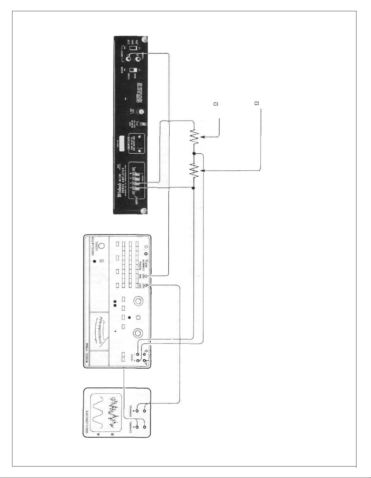
JOINT"
GAUGE SOLDER
"SOLDER
8
96' OF 20
INDUCTIVE
NON
LOAD RESISTOR
8
SET UP
MEASURING TEST
DISTORTION
 Loading...