


INSTALLATION INSTRUCTIONS
OVER-THE-RANGE MICROWAVE OVEN
IMPORTANT: Read all installation instructions thoroughly before installing your microwave oven.
TABLE OF CONTENTS
Requirements for Installation
Important Safety Instructions . . . . . . . . . . . . . . . . . . . . . . . . . . . . 2 Grounding Instructions . . . . . . . . . . . . . . . . . . . . . . . . . . . . . . . . . 2 Mounting Space . . . . . . . . . . . . . . . . . . . . . . . . . . . . . . . . . . . . . . . 3 Wall Construction . . . . . . . . . . . . . . . . . . . . . . . . . . . . . . . . . . . . . . 3 Tools, Parts and Materials . . . . . . . . . . . . . . . . . . . . . . . . . . . . . . . 4 Venting System. . . . . . . . . . . . . . . . . . . . . . . . . . . . . . . . . . . . . . . . 5 Prepare Hood Fan (Roof or Wall Venting) . . . . . . . . . . . . . . . . . . 6 Hood Exhaust Duct. . . . . . . . . . . . . . . . . . . . . . . . . . . . . . . . . . . . . 8
Installation Procedure
Prepare Cabinet Opening. . . . . . . . . . . . . . . . . . . . . . . . . . . . . . . . 10 Mounting Templates . . . . . . . . . . . . . . . . . . . . . . . . . . . . . . . . 10 Drill holes in the wall and upper cabinet template . . . . . . . . 11 Drill the power supply cord hole . . . . . . . . . . . . . . . . . . . . . . . 12 Cut the opening required for the duct. . . . . . . . . . . . . . . . . . . 12
Install Mounting Plate . . . . . . . . . . . . . . . . . . . . . . . . . . . . . . . . . . 12 Mount the Microwave Oven . . . . . . . . . . . . . . . . . . . . . . . . . . . . . 13 Check List . . . . . . . . . . . . . . . . . . . . . . . . . . . . . . . . . . . . . . . . . . . . 16
INSTRUCTIONS D’INSTALLATION . . . . . . . . . . . . . . . . . . . . . . . . 17 INSTRUCCIONES DE INSTALACIÓN . . . . . . . . . . . . . . . . . . . . . . . 33
1
IMPORTANT SAFETY INSTRUCTIONS
WARNING - When using electrical appliances, basic safety precautions should be followed, including the following:
•Install microwave oven as specified in Installation Instructions or as specified on wall or upper cabinet templates.
•It is recommended that two people including a qualified technician install this microwave oven.
•The microwave oven needs to be mounted against and supported by both a flat, vertical wall and an upper cabinet or other horizontal structure.
•The mounting surface must be capable of supporting weight of 150 pounds plus the weight of any items you place inside the oven or upper cabinet.
•Do not mount this product to an island or peninsula cabinet.
•Remove house fuse or open circuit
breaker before beginning installation to avoid severe or fatal shock injury.
•Before you drill into the wall, note where electrical outlets are and where electrical wires might be concealed behind the wall. If you contact electrical wires with your drill bit, you could get an electric shock.
•Save these instructions for the local electrical inspector’s use.
•Do not use this microwave oven for commercial purposes. It is designed for household use only.
•This microwave oven is factory set for room venting operation. To vent through the wall or roof, changes must be made to venting system.
•If the cabinet is covered with a protective film, remove the film.
READ AND SAVE THESE INSTRUCTIONS
GROUNDING INSTRUCTIONS
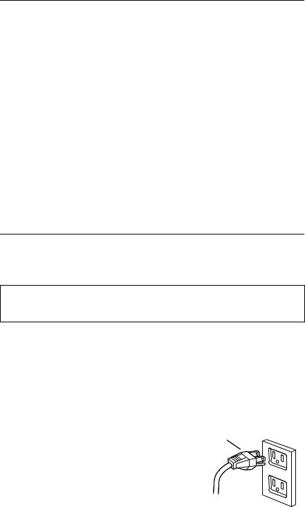
This appliance must be grounded. In the event of an electrical short circuit, grounding reduces the risk of electric shock by providing an escape wire for the electric current. This appliance is equipped with a cord having a grounding wire with a grounding plug. The plug must be plugged into an outlet that is properly installed and grounded.
DANGER - Improper use of the grounding plug can result in a risk of electric shock. Do not plug into an outlet until appliance is properly installed and grounded.
Consult a qualified electrician if the grounding instructions are not completely understood, or if doubt exists as to whether the appliance is properly grounded.
•Electrical rating is 120 volts, AC,
60 Hertz. This microwave oven must be connected to a supply circuit of proper voltage and frequency.
•The power supply cord and plug should be brought to a separate
15 to 20 ampere branch circuit single grounded outlet. The outlet box should be located in the cabinet above the microwave oven.
•The outlet box and supply circuit should be installed by a qualified electrician and conform to the
National Electric Code and the prevailing local code.
•Where a standard two-prong wall receptacle is encountered, replace it with a properly grounded threeprong wall receptacle, installed by a qualified electrician.
•Do not use an extension cord.
•Do not remove or cut any of the prongs from the power cord.
NOTE: The dealer can not accept any liability for damage to the oven or personal injury resulting from failure to observe the correct electrical connection procedures. It is the customer’s responsibility.
Three-pronged (grounding) plug
Recommended Grounding Method
2

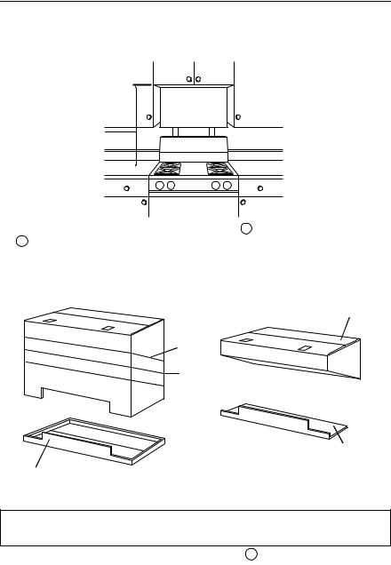
MOUNTING SPACE
Your microwave oven requires mounting space on a wall as shown.
• 13" recommended upper cabinet |
• The bottom of the microwave oven |
depth. |
should be at least 2" above the |
• The bottom edge of the cabinet |
range backsplash for proper |
that will be above the microwave |
installation and servicing. |
oven is at least 30" from the |
• 30” width is required to mount the |
cooking surface. |
microwave oven. |
13"
30"
2" |
Wall Stud |
30"
WALL CONSTRUCTION
This microwave oven should be mounted against and supported by a flat, vertical wall.
• To find the location of the studs, |
• After locating the stud, the center |
one of following methods may be |
can be found by probing the wall |
used: |
with a small nail to find the edges |
1. Stud Finder--magnetic device |
of the stud and then placing a mark |
which locates nails in the stud. |
halfway between the edges. |
2. Use a hammer to tap lightly |
• Wall construction should be a |
across the mounting surface to |
minimum of 2" x 4" wood studding |
find a solid sound. |
and 3/8" or more thick drywall or |
|
plaster/lath. |
|
• Studs are usually at regular |
|
intervals spaced 16" or 24” apart. |
3
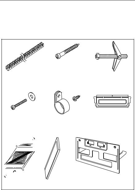
TOOLS, PARTS AND MATERIALS
Remove the microwave oven and all materials from the carton. To install microwave over the range, you will need following materials and tools. Check all materials and accessories before you begin installation. If you find some parts missing, contact an Authorized Service Center.
Parts you need to install your oven
(You may not need to use all of these parts.)
• |
Upper Cabinet Template |
1 |
• |
Wall Template |
1 |
Power Supply Cord Bushing (1) |
1/ ” x 2” Wood Screw |
1/ |
” x 3” Bolt and Spring |
Use with metal cabinet. |
4 |
4 |
|
(4 screws) |
Toggle Heads (4 each) |
||
For drywall holes.
1/4” x 3” Bolt and Washer |
Power Supply Cord Clamp |
Damper Assembly (1) |
(2 each) |
and Mounting Screw |
For roof/ wall venting |
To secure to the upper |
(1 each) |
installation. |
cabinet. |
To hold the power cord. |
|
Grease Filter (2)
,
Charcoal Filter (2) For room venting.
Mounting Plate (1)
Attached on back of microwave.
Tools recommended for installation
• |
Phillips screwdriver |
• |
3/4” wood drill bit |
• |
Pencil |
• |
Stud finder |
• |
Measuring tape |
• 2” diameter hole drill bit |
|
• |
Clear tape |
• |
Hammer |
• |
Duct tape |
• |
Caulk (wall venting) |
•Electric drill
•Keyhole saw
•3/8” wood drill bit
4
VENTING SYSTEM
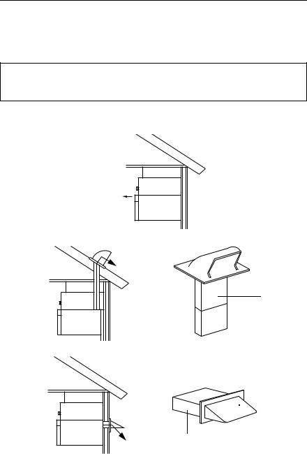
This microwave oven is set for room venting installation. For roof or wall venting, changes to the venting system must be made. If wall venting is chosen, make sure there is proper clearance within the wall for the exhaust vent.
This oven is designed for adaptation to the following three types of ventilation. Select the type of ventilation required for your installation.
CAUTION: To reduce risk of fire and to properly exhaust air, be sure to vent air correctly. Do not vent exhaust air into spaces within walls or ceilings or into attics, crawl spaces or garages.
A.Room venting
The charcoal filters are required for room venting installation.
This venting system is normally used for condominiums or apartments.
B. Roof venting

 Roof cap
3-1/4” x10” through-the- roof ducting
C. Wall venting
 Wall cap
3-1/4” x10” through- the-wall ducting
NOTE:
•The duct work and cap you need for wall or roof venting are not included. All wall and roof caps must have a back-draft damper.
•Check the exhaust duct and change it if required. (See pages 8 - 9 for more information.)
•We recommend that a qualified electrician install the venting system.
5
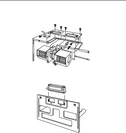
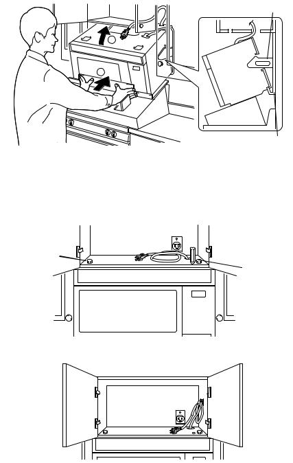
PREPARE HOOD FAN
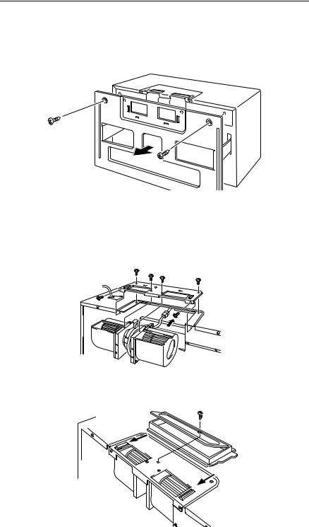
Your microwave oven is shipped with the blower assembled for room venting. If wall or roof venting is chosen, it is necessary for you to change vent blower to the appropriate orientation for the chosen venting system.
The mounting plate comes attached to the back of microwave oven. Remove and save the two screws from the mounting plate. Remove the mounting plate.
ROOF VENTING
•Remove the 6 screws that attach frame bracket to top of microwave oven. Carefully slide hood fan out of the microwave oven. Rotate hood fan so that exhaust ports of hood fan face the top of microwave oven. Slide hood fan back into microwave oven as far as it will go. Check that exhaust ports face the top of microwave oven. The wires will extend far enough to allow you to adjust hood fan.
•Reattach frame bracket with 6 screws.
•Check that damper assembly moves freely before you insert it into frame bracket. Slide and insert damper assembly into frame bracket as shown.
6
PREPARE HOOD FAN
WALL VENTING
•Remove the 6 screws that attach frame bracket to top of microwave oven. Carefully slide hood fan out of the microwave oven. Rotate hood fan so that the exhaust ports face the rear of the microwave oven as shown. Place hood fan back into microwave oven.
•Reattach frame bracket with 6 screws.
•Check that damper assembly moves freely before you insert it into frame bracket. Slide and insert damper assembly into frame bracket as shown.
7
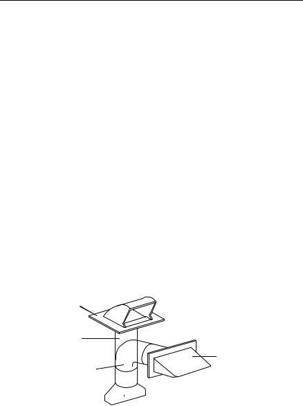
HOOD EXHAUST DUCT
•For roof or wall venting, a hood exhaust duct is required.
•Check that all connections are securely made.
•All duct work must be metal.
Exhaust Connection: The hood exhaust has been designed to connect to a standard 3-1/4" x 10" rectangular duct.
If a round duct is required, a rectangular-to-round transition adaptor must be used. Do not use a duct that is less than 6" in diameter.
Wall Exhaust: If wall exhausting is to be used, care should be taken to align the exhaust with the space between the studs, or wall should be prepared at the time it is constructed by leaving enough space between wall studs to accommodate duct work.
The total length of the vent system including straight vent, elbow, transitions, wall or roof caps must not exceed the equivalent of 140 feet of 3-1/4" x 10” rectangular or 6” diameter round vent (see page 9).
Recommendations:
•Use rigid metal vents.
•Length of vent and number of elbows should be kept to a minimum to provide efficient performance.
•Size of vent should be uniform.
•Use duct tape to seal all joints in the vent system.
•Do not use elbows exceeding 90 degrees.
•Do not install two elbows together.
•Use caulking to seal the exterior wall or roof opening around the cap.
•Do not use flexible metal vents.
Round Vent Transition
Roof cap
6” min. diameter round vent
Wall cap
Elbow

 3-1/4” x 10” to 6” vent transition
8

HOOD EXHAUST DUCT
NOTE: Total length must not exceed the equivalent of 140 Ft.
3-1/4”x10” rectangular vent system |
6” round vent system |
||
3-1/ ” x 10” |
|
|
|
|
6ft. |
|
|
4 |
|
|
|
90° elbow |
|
|
|
|
|
|
|
6ft.
|
|
2ft. |
2ft. |
Wall cap |
|
|
|
|
|
Transition |
90° elbows |
|
|
One 90 degree elbow (25 ft.) |
=25 ft. |
Wall cap (40 ft.) |
=40 ft. |
8 feet straight duct |
= 8 ft. |
Total length |
=73 ft. |
Recommended Standard Fittings
3-1/4” x 10” to 6” transition (5 ft.)= 5 ft.
Two 90 degree elbows (10 ft.) |
=20 ft. |
Wall cap (40 ft.) |
=40 ft. |
8 feet straight duct |
= 8 ft. |
Total length |
=73 ft. |
3-1/ ” x 10” to 6” (5 ft.) |
3-1/4” x 10” roof cap (24 ft.) |
3-1/4” x 10” 90° elbow (25 ft.) |
|
4 |
|
|
|
45° elbow (5 ft.) |
|
90° elbow (10 ft.) |
45° elbow (5 ft.) |
3-1/4” x 10” flat elbow (10 ft.) |
3-1/ ” x 10” wall cap (40 ft.) |
||
|
|
4 |
|
|
|
9 |
|
INSTALLATION PROCEDURE
PREPARE CABINET OPENING
•Remove burner grates (if there are any) from top of the range and place a piece of cardboard or other heavy material over the countertop or cooktop to protect it. Failure to protect these surfaces could result in product damage.
•Remove microwave, all shipping materials and parts. Check the microwave for any damage such as a misaligned or bent door, damaged door seals and sealing surfaces, broken or loose door hinges and latches and dents inside the cavity or on the door. If there is any damage, do not install the oven and contact an Authorized Service Center.
MOUNTING TEMPLATES
This product comes with an upper cabinet template and a wall template to help ensure proper installation.
•Locate the center of the opening where the oven is to be installed. Using a measuring tape, find and clearly mark the vertical center line of the cabinet opening on the wall directly under the upper cabinet.
•Line up paper wall template center line with center line on wall. Tape wall template to wall. Top of template must be located a minimum of 30" above cooking surface or countertop.
NOTE: Top of wall template must be on the same level as the front edge of cabinet. THE MICROWAVE OVEN MUST BE LEVEL.
Back wall
•Find and mark the location of all wall studs on wall template. If there are no wall studs in the opening area, do not install microwave oven and consult with your building inspector.
CAUTION: Do not attempt to install the microwave oven if you cannot find a wall stud.
•Measure bottom of upper cabinet to line up the paper upper cabinet template. Trim the edges of A, B and C on upper cabinet template so template will fit on bottom of upper cabinet. If upper cabinet has a frame and the bottom of cabinet is recessed, trim template to fit inside the recessed area. Align center line of upper cabinet template with center line of wall template. Tape to cabinet bottom.
10
DRILL HOLES IN THE WALL AND UPPER CABINET TEMPLATE
•Turn off electricity at the fuse box for any outlets or circuits located in the area you will be drilling or cutting.
DANGER: Special care must be taken when drilling holes into the wall. Electrical wires could be concealed behind the wall covering and if the drill hits them you could get an electric shock.
•Check if points D and E or F and G on wall template are over a wall stud.
If points are over a wall stud, drill 3/16" holes. If points are over drywall, drill 3/4" holes.
•If there are no wall studs at points D, E, F, G or at only one set of points, find within area H and I the screw points closest to the center of wall stud. Drill 3/16" holes into wall stud. If there is no stud, drill 3/4" holes.
The microwave must be connected to at least one wall stud. Make sure to use 2 wood screws in a stud, and 4 toggle bolts in the drywall or the plaster to secure mounting plate to wall. IF THERE IS NO STUD WITHIN THE AREAS MARKED H, I AND NOT BEHIND POINTS D, E, F AND G, DO NOT INSTALL MICROWAVE OVEN.
•Find the points on the upper cabinet template labeled J, K and N. Drill 3/8" diameter holes.
•The marked points J, K will be used to secure microwave oven to upper cabinet.The marked point N will be used to secure microwave oven temporarily.
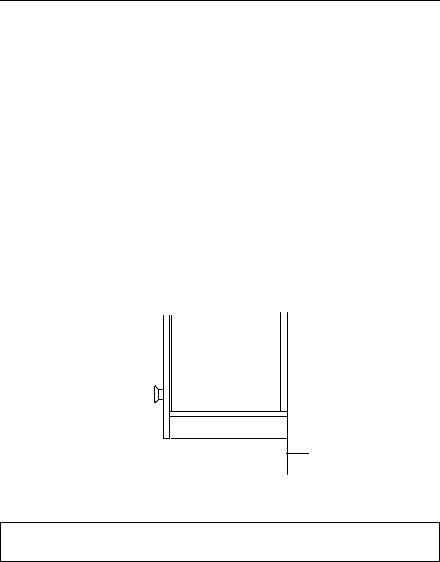
Filler Block
•If the bottom of the upper cabinet is recessed 3/4" or more, you must use 2" x 2" filler blocks (not included) to provide additional support for the bolts.
Cabinet bottom shelf
Cabinet
front
 Filler block
•Mark the center of each filler block and drill a 3/8" diameter hole at the marks.
•Align filler blocks over the two openings in the top of the microwave oven cabinet and attach to cabinet with masking tape.
 Filler
blocks
11
DRILL THE POWER SUPPLY CORD HOLE
•Cut or drill a 2" diameter hole at the area marked M for the power supply cord hole on the upper cabinet template.
NOTE: If the upper cabinet is metal, you will need to cover the edge of the hole with the power supply cord bushing to prevent damage to the cord from the rough metal edge.
WARNING: cover the edge of the power supply cord hole in a metal cabinet with the power supply cord bushing. Failure to do so could result in damage to the cord and may cause electric shock.
CUT THE OPENING REQUIRED FOR THE DUCT
•Room Venting: Remove the upper cabinet and wall templates and go to next step, INSTALL MOUNTING PLATE.
•Roof Venting: Cut out the shaded area marked L on the upper cabinet template with keyhole saw. Remove the upper cabinet and wall templates. Go to next step, INSTALL MOUNTING PLATE.
•Wall Venting: Cut out the shaded area marked O on the Wall template with keyhole saw. Remove the upper cabinet and wall templates. Insert wall vent through vent opening. Use caulking to seal wall opening around exhaust cap. Go to next step, INSTALL MOUNTING PLATE.
INSTALL MOUNTING PLATE
•Remove any adhesive tape from door. Take out all the items from inside the oven. Put adhesive tape back on the door.
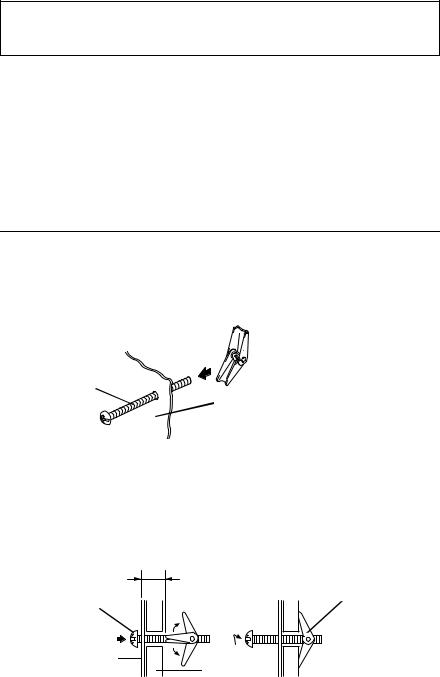
•Insert 1/4" x 3" toggle bolts through holes in mounting plate that match the location of the 3/4" holes in the drywall. Start a spring toggle nut on the end of each toggle bolt. Leave enough space for the toggle to open when pushed through the wall.

 Spring toggle head
1/4" x 3” toggle bolt 
 Mounting Plate
•Position mounting plate on the wall. Push toggle bolts and nuts through the holes in the drywall.
NOTE: Insert 4, 1/4" x 2" wood screws into 3/16" holes drilled into wooden wall stud. Make sure that top of mounting plate is on the same level as the front edge of cabinet bottom or cabinet frame, securely tighten wood screws and toggle bolts.
When tightening toggle bolts, make sure toggle heads have opened against drywall by leaving at least one wall thickness of space between the head of the toggle bolt and the spring toggle head.
1/4" x 3” toggle Spring toggle head bolt head
Mounting Plate
Wall
12
MOUNT THE MICROWAVE OVEN
Carton will be used in order to assist positioning the microwave oven during mounting.
•Measure the height from cooking surface (or countertop) to the bottom edge of the top cabinet.
Measure here
•Cut out carton A along one of the dotted lines A . Determine the correct line A according to the height you just measured (Fig. 1).
Example: If the height is 33", cut the line marked 33".
If the correct height is not shown on the box, draw a line between the two closest lines. For example, if the height is 32", draw a line 2" below the line marked 30", and then cut the box along the line you have drawn.
Carton A
 30”
30”
33”
 36”
36”
Carton B’
Carton B |
Fig. 2 |
|
Fig. 1 |
||
|
If the dimension is over 36”, do not use carton. At least two people will be required to lift and mount the microwave oven.
•Cut out carton B (Fig. 1) along the dotted line B . Then remove staple on the bottom of carton B (carton B’, Fig. 2).
•Place cut portion of Carton A on top of the range.
NOTE: Prepare phillips screw driver, bolts and washers on top of the upper cabinet. Protection of the range cooking surface is recommended.
13

•Place cut portion of Carton B on top of the Carton A. At this point, cut Area C as shown and turn flaps upward.
 Carton B
Area C
Carton A
•After you have placed cut portion of Carton B as shown above, bend Area C and secure carton with tape as shown below.
Area C
 Carton B
Tape
•Place microwave oven on top of carton B and A as shown. Remove tape and lift up Area C. Thread power supply cord through the power supply cord hole in the bottom of the upper cabinet.
NOTE: Lift flaps in Area C to help prevent microwave oven from slipping off of carton.
Area C 

WARNING: Be careful when lifting microwave oven. It is recommended that two people lift and install this microwave oven. Failure to use more than one person could result in personal injury.
14
•Raise the flap on Carton B as shown and carefully slide microwave oven up with Carton B until it hangs on support tabs at the bottom of mounting plate. NOTE: There are holes on back of microwave oven. The arm on mounting plate should fit into these holes until the microwave oven touches and hooks onto the wall.
Arm
2
1
Support tabs
•Rotate microwave upward so that top of oven is against bottom of upper cabinet or cabinet frame.
•Drop a phillips screw driver into hole N from above and push it down as far as it will go. Pull the screw driver towards you until the gap between the upper cabinet and microwave oven is closed. Place washers over two 1/4" x 3" bolts. Insert bolt down through each hole in the upper cabinet bottom. Remove screw driver and tighten two bolts with a screw driver.
 Screw driver
1/4" x 3” bolt with
washer |
1/4" x 3” bolt |
|
|
|
with washer |
•Coil power supply cord through clamp. Secure clamp to cabinet side with mounting screw.
 Clamp
Clamp
15
 Loading...