


Maytag MEDB750YW2, MEDB850YG2, MEDB950YW2, MEDB850YW2, MEDB850YG1 Installation Instructions Manual
...
Electric Dryer Installation Instructions
Table of Contents
DRYER SAFETY ......................................................................... 2
iNSTALLATiON REQUIREMENTS ............................................. 3
Tools and Parts ...................................................................... 3
LOCATION REQUIREMENTS .................................................... 4
ELECTRICAL REQUIREMENTS ................................................ 5
iNSTALL LEVELING LEGS ......................................................... 6
ELECTRICAL CONNECTION .................................................... 7
Power Supply Cord Connection ........................................... 7
Direct Wire Connection ......................................................... 9
VENTING ................................................................................... 12
Venting Requirements ......................................................... 12
PLAN VENT SYSTEM ............................................................... 13
iNSTALL VENT SYSTEM ......................................................... 15
CONNECT iNLET HOSES ........................................................ 15
CONNECT VENT ...................................................................... 17
LEVEL DRYER .......................................................................... 17
COMPLETE iNSTALLATiON CHECKLIST .............................. 18
REVERSE DOOR SWING ......................................................... 18
TROUBLESHOOTING .............................................................. 19
iNSTALLATiON NOTES
Date of purchase:
Date of installation:
Installer:
Model number:
Serial number:
Para obtener acceso al manual de uso y cuidado en espa_ol, o para obtener informaci6n
adicional acerca de su producto, visite: www.whirlpool.com
Tenga listo su nOmero de modelo completo. Puede encontrar el nOmero de modelo
y de serie dentro de la cavidad superior de la puerta.
W10392124A
W10392125A-SP
DRYER S_ETY
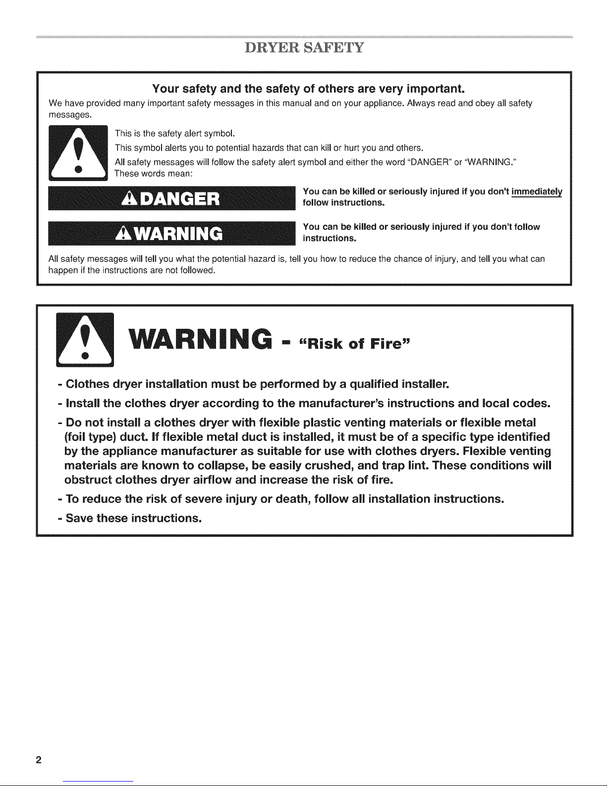
Your safety and the safety of others are very important.
We have provided many important safety messages in this manual and on your appliance. Always read and obey all safety
messages.
This is the safety alert symbol.
This symbol alerts you to potential hazards that can kill or hurt you and others.
All safety messages will follow the safety alert symbol and either the word "DANGER" or "WARNING."
These words mean:
You can be killed or seriously injured if you don't immediately
follow instructions.
You can be killed or seriously injured if you don't follow
instructions.
All safety messages will tell you what the potential hazard is, tell you how to reduce the chance of injury, and tell you what can
happen if the instructions are not followed.
WARNING - ,,.i.. ofFi..,,
- Clothes dryer installation must be performed by a qualified installer,
- install the clothes dryer according to the manufacturer's instructions and local codes.
- Do not install a clothes dryer with flexible plastic venting materials or fle×ible metal
(foil type) duct. if flexible metal duct is installed, it must be of a specific type identified
by the appliance manufacturer as suitable for use with clothes dryers. Flexible venting
materials are known to collapse, be easily crushed, and trap lint. These conditions will
obstruct clothes dryer airflow and increase the risk of fire.
- To reduce the risk of severe injury or death, follow all installation instructions.
- Save these instructions.
2
IN$ LATION REQUIREMENTS
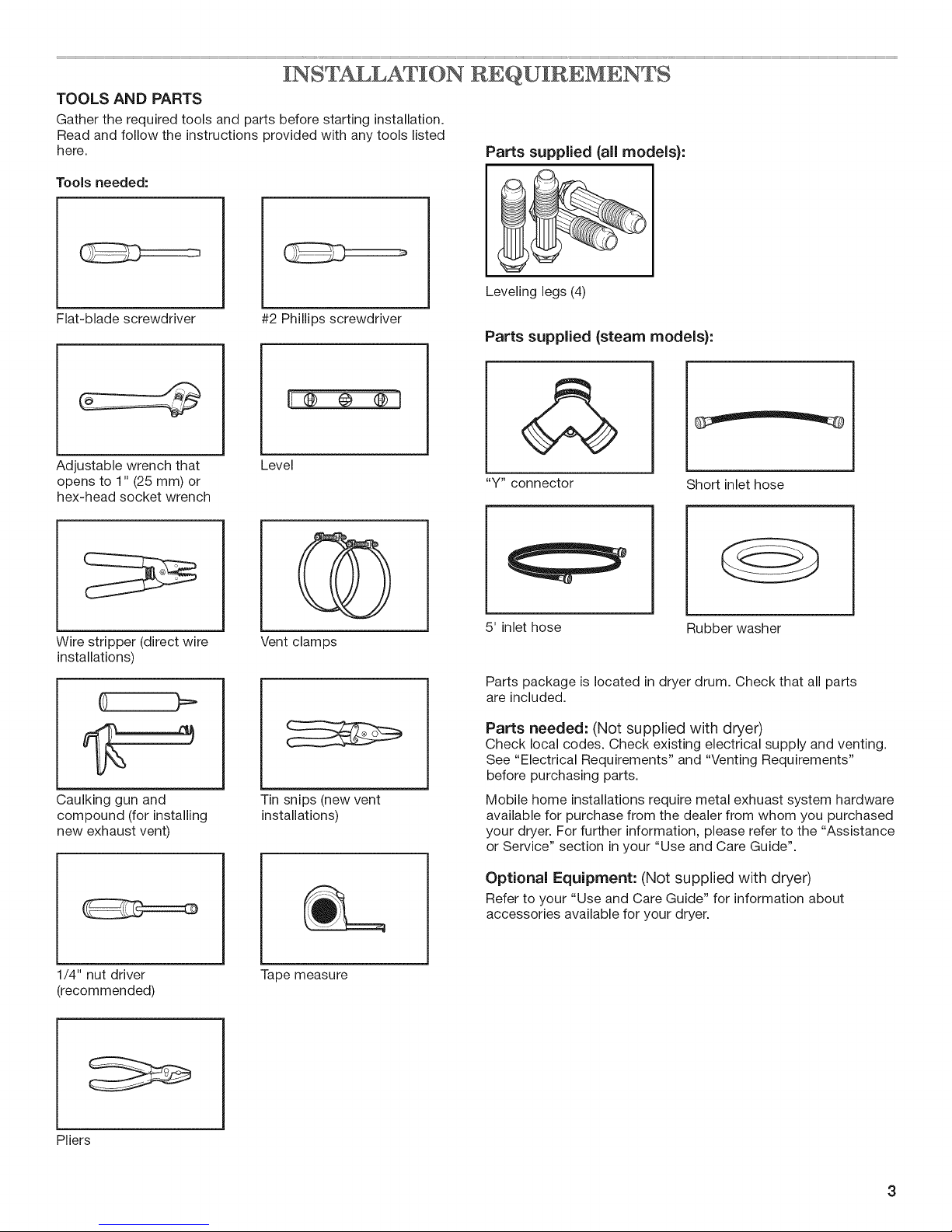
TOOLS AND PARTS
Gather the required tools and parts before starting installation.
Read and follow the instructions provided with any tools listed
here. Parts supplied {all models):
Tools needed:
Leveling legs (4)
Flat-blade screwdriver
#2 Phillips screwdriver
Parts supplied {steam models):
I1®®®1
&
Adjustable wrench that
opens to 1" (25 mm) or
hex-head socket wrench
Wire stripper (direct wire
installations)
Caulking gun and
compound (for installing
new exhaust vent)
Level
Vent clamps
Tin snips (new vent
installations)
"Y" connector
5' inlet hose Rubber washer
Parts package is located in dryer drum. Check that all parts
are included.
Parts needed: (Not supplied with dryer)
Check local codes. Check existing electrical supply and venting.
See "Electrical Requirements" and "Venting Requirements"
before purchasing parts.
Mobile home installations require metal exhuast system hardware
available for purchase from the dealer from whom you purchased
your dryer. For further information, please refer to the "Assistance
or Service" section in your "Use and Care Guide".
Optional Equipment: (Not supplied with dryer)
Refer to your "Use and Care Guide" for information about
accessories available for your dryer.
Short inlet hose
1/4" nut driver
(recommended)
Pliers
Tape measure
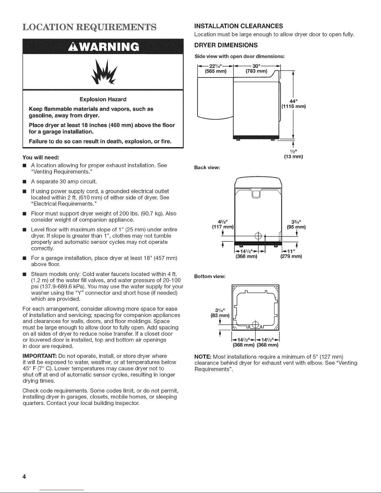
INSTALLATION CLEARANCES
Location must be large enough to allow dryer door to open fully.
DRYER DiMENSiONS
Side view with open door dimensions:
22%"---_
(565 ram}
30"-----_
Explosion Hazard
Keep flammable materials and vapors, such as
gaso|ine, away from dryer.
Place dryer at least 18 inches (460 ram) above the floor
for a garage installation.
Failure to do so can result in death, explosion, or fire.
You will need:
[]
A location allowing for proper exhaust installation. See
"Venting Requirements."
[]
A separate 30 amp circuit.
[]
If using power supply cord, a grounded electrical outlet
located within 2 ft. (610 mm) of either side of dryer. See
"Electrical Requirements."
[]
Floor must support dryer weight of 200 Ibs. (90.7 kg). Also
consider weight of companion appliance.
[]
Level floor with maximum slope of 1" (25 mm) under entire
dryer. If slope is greater than 1", clothes may not tumble
properly and automatic sensor cycles may not operate
correctly.
[]
For a garage installation, place dryer at least 18" (457 mm)
above floor.
[]
Steam models only: Cold water faucets located within 4 ft.
(1.2 m) of the water fill valves, and water pressure of 20-100
psi (137.9-689.6 kPa). You may use the water supply for your
washer using the "Y" connector and short hose (if needed)
which are provided.
For each arrangement, consider allowing more space for ease
of installation and servicing; spacing for companion appliances
and clearances for walls, doors, and floor moldings. Space
must be large enough to allow door to fully open. Add spacing
on all sides of dryer to reduce noise transfer. If a closet door
or Iouvered door is installed, top and bottom air openings
in door are required.
IMPORTANT." Do not operate, install, or store dryer where
it will be exposed to water, weather, or at temperatures below
45° F (7° C). Lower temperatures may cause dryer not to
shut off at end of automatic sensor cycles, resulting in longer
drying times.
Check code requirements. Some codes limit, or do not permit,
installing dryer in garages, closets, mobile homes, or sleeping
quarters. Contact your local building inspector.
44"
(1118 ram)
W=========_n
i
1/2H
(13 ram)
Back view:
45/8"
(I17ram)
_14,112"-_'-I-_4 -4-11"
(368 ram) (279mm)
Bottom view:
31/4"
(83_nm)
+
"_-141/2'''_ -_-141/2'''_
(368 ram} (368 ram)
NOTE: Most installations require a minimum of 5" (127 mm)
clearance behind dryer for exhaust vent with elbow. See "Venting
Requirements".
33/4"
(95_m)
4
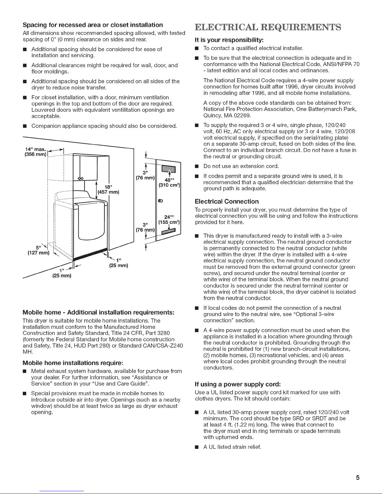
Spacing for recessed area or closet installation
All dimensions show recommended spacing allowed, with tested
spacing of 0" (0 ram) clearance on sides and rear.
[] Additional spacing should be considered for ease of
installation and servicing.
[] Additional clearances might be required for wall, door, and
floor moldings.
[] Additional spacing should be considered on all sides of the
dryer to reduce noise transfer.
For closet installation, with a door, minimum ventilation
openings in the top and bottom of the door are required.
Louvered doors with equivalent ventilitation openings are
acceptable.
[] Companion appliance spacing should also be considered.
14" max,
(356 rnm) l
g
(76
g
(76
(127 mm)
(25 rnm)
Mobile home = Additional installation requirements:
This dryer is suitable for mobile home installations. The
installation must conform to the Manufactured Home
Construction and Safety Standard, Title 24 CFR, Part 3280
(formerly the Federal Standard for Mobile home construction
and Safety, Title 24, HUD Part 280) or Standard CAN/CSA-Z240
MH.
Mobile home installations require:
[] Metal exhaust system hardware, available for purchase from
your dealer. For further information, see "Assistance or
Service" section in your "Use and Care Guide".
[]
Special provisions must be made in mobile homes to
introduce outside air into dryer. Openings (such as a nearby
window) should be at least twice as large as dryer exhaust
opening.
ELECTRIC, REQUIREMENWS
it is your responsibility:
[] To contact a qualified electrical installer.
[] To be sure that the electrical connection is adequate and in
conformance with the National Electrical Code, ANSVNFPA 70
- latest edition and all local codes and ordinances.
The National Electrical Code requires a 4-wire power supply
connection for homes built after 1996, dryer circuits involved
in remodeling after 1996, and all mobile home installations.
A copy of the above code standards can be obtained from:
National Fire Protection Association, One Batterymarch Park,
Quincy, MA 02269.
[]
To supply the required 3 or 4 wire, single phase, 120/240
volt, 60 Hz, AC only electrical supply (or 3 or 4 wire, 120/208
volt electrical supply, if specified on the serial/rating plate)
on a separate 30-amp circuit, fused on both sides of the line.
Connect to an individual branch circuit. Do not have a fuse in
the neutral or grounding circuit.
[] Do not use an extension cord.
[] If codes permit and a separate ground wire is used, it is
recommended that a qualified electrician determine that the
ground path is adequate.
Electrical Connection
To properly install your dryer, you must determine the type of
electrical connection you will be using and follow the instructions
provided for it here.
[]
This dryer is manufactured ready to install with a 3-wire
electrical supply connection. The neutral ground conductor
is permanently connected to the neutral conductor (white
wire) within the dryer. If the dryer is installed with a 4-wire
electrical supply connection, the neutral ground conductor
must be removed from the external ground connector (green
screw), and secured under the neutral terminal (center or
white wire) of the terminal block. When the neutral ground
conductor is secured under the neutral terminal (center or
white wire) of the terminal block, the dryer cabinet is isolated
from the neutral conductor.
[]
If local codes do not permit the connection of a neutral
ground wire to the neutral wire, see "Optional 3-wire
connection" section.
[]
A 4-wire power supply connection must be used when the
appliance is installed in a location where grounding through
the neutral conductor is prohibited. Grounding through the
neutral is prohibited for (1) new branch-circuit installations,
(2) mobile homes, (3) recreational vehicles, and (4) areas
where local codes prohibit grounding through the neutral
conductors.
If using a power supply cord:
Use a UL listed power supply cord kit marked for use with
clothes dryers. The kit should contain:
[]
A UL listed 30-amp power supply cord, rated 120/240 volt
minimum. The cord should be type SRD or SRDT and be
at least 4 ft. (1.22 m) long. The wires that connect to
the dryer must end in ring terminals or spade terminals
with upturned ends.
[] A UL listed strain relief.
if your outlet looks like this:
Then choose a 4-wire power supply cord with
ring or spade terminals and UL listed strain
relief. The 4-wire power supply cord, at least
4 ft. (1.22 m) long, must have 4 10-gauge solid
copper wires and match a 4-wire receptacle of
4-wire
receptacle
(14-30R)
If your outlet looks like this:
3-wire
receptacle
(10-30R)
NEMA Type 14-30 R. The ground wire (ground
conductor) may be either green or bare. The
neutral conductor must be identified by a
white cover.
Then choose a 3-wire power supply cord with
ring or spade terminals and UL listed strain
relief. The 3-wire power supply cord, at least
4 ft. (1.22 m) long, must have 3 10-gauge solid
copper wires and match a 3-wire receptacle of
NEMA Type 10-30R.
INSTALL LE¥ LING LEGS
Excessive Weight Hazard
Use two or more people to move and install dryer.
Failure to do so can result in back or other injury.
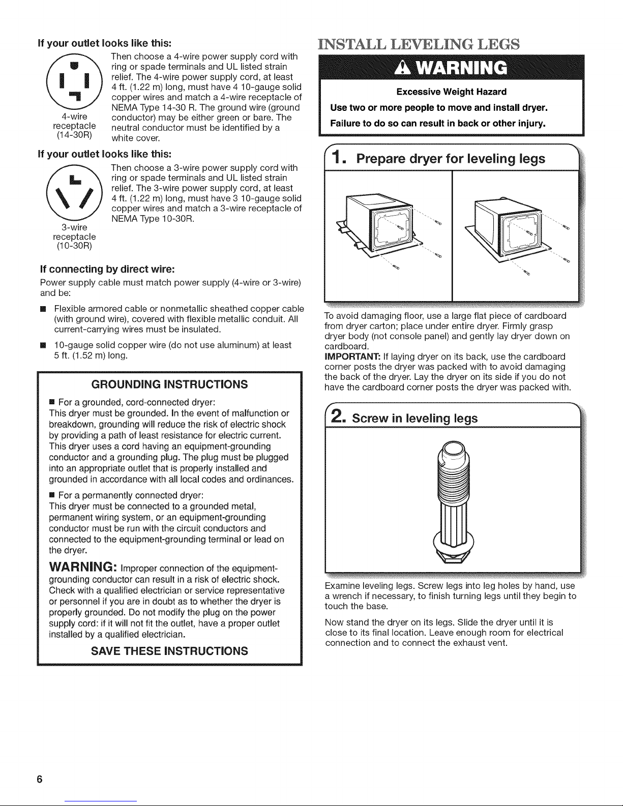
"1, Prepare dryer for leveling legs
If connecting by direct wire:
Power supply cable must match power supply (4-wire or 3-wire)
and be:
[] Flexible armored cable or nonmetallic sheathed copper cable
(with ground wire), covered with flexible metallic conduit. All
current-carrying wires must be insulated.
[] 10-gauge solid copper wire (do not use aluminum) at least
5 ft. (1.52 m) long.
GROUNDING INSTRUCTIONS
[] For a grounded, cord-connected dryer:
This dryer must be grounded, in the event of malfunction or
breakdown, grounding will reduce the risk of electric shock
by providing a path of least resistance for electric current.
This dryer uses a cord having an equipment-grounding
conductor and a grounding plug. The plug must be plugged
into an appropriate outlet that is properly installed and
grounded in accordance with all local codes and ordinances.
[] For a permanently connected dryer:
This dryer must be connected to a grounded metal,
permanent wiring system, or an equipment-grounding
conductor must be run with the circuit conductors and
connected to the equipment-grounding terminal or lead on
the dryer.
WARNING: Improper connection of the equipment-
grounding conductor can result in a risk of electric shock.
Check with a qualified electrician or service representative
or personnel if you are in doubt as to whether the dryer is
properly grounded. Do not modify the plug on the power
supply cord: if it will not fit the outlet, have a proper outlet
installed by a qualified electrician.
SAVE THESE INSTRUCTIONS
"%
To avoid damaging floor, use a large flat piece of cardboard
from dryer carton; place under entire dryer. Firmly grasp
dryer body (not console panel) and gently lay dryer down on
cardboard.
IMPORTANT: If laying dryer on its back, use the cardboard
corner posts the dryer was packed with to avoid damaging
the back of the dryer. Lay the dryer on its side if you do not
have the cardboard corner posts the dryer was packed with.
Screw in leveling legs
Examine leveling legs. Screw legs into leg holes by hand, use
a wrench if necessary, to finish turning legs until they begin to
touch the base.
Now stand the dryer on its legs. Slide the dryer until it is
close to its final location. Leave enough room for electrical
connection and to connect the exhaust vent.
6
 Loading...