


System Manual
MAXDATA PLATINUM 220 Server

2 Contents
3MAXDATA PLATINUM 220 Server

3MAXDATA PLATINUM 220 Server
Contents
1 Setting up the system 5
Server position ........................................................................................................................................5
Connecting the system ........................................................................................................................... 6
Rear Connectors.................................................................................................................................6
Powering up the system ......................................................................................................................... 6
2 Server Description 7
Back Panel Connectors ...........................................................................................................................8
Server Board Connector and Component Locations ...............................................................................9
Processor ..............................................................................................................................................10
Memory.................................................................................................................................................10
Intel® 875P Chipset ...............................................................................................................................11
Intel® 82875P Memory Controller Hub (MCH) .................................................................................11
Intel® 82801ER I/O Controller Hub (ICH5-R).....................................................................................11
Video .....................................................................................................................................................12
AGP Connector.................................................................................................................................12
ATI Rage XL Video Controller ...........................................................................................................12
Video Modes ....................................................................................................................................12
Super I/O ............................................................................................................................................... 13
Serial Port .........................................................................................................................................13
Parallel Port ......................................................................................................................................14
Floppy Drive Controller..................................................................................................................... 14
Keyboard and Mouse Connectors ....................................................................................................14
USB ....................................................................................................................................................... 14
High-Speed USB 2.0 Support ...........................................................................................................14
Legacy USB Support ........................................................................................................................14
PCI I/O Subsystem ................................................................................................................................15
Data Storage..........................................................................................................................................16
Serial ATA (SATA)............................................................................................................................. 16
IDE Interfaces...................................................................................................................................16
Network Interface Controller (NIC)........................................................................................................17
NIC Connector and Status LEDs ......................................................................................................17
Power Management..............................................................................................................................18
Software Support through ACPI....................................................................................................... 18
Wake-up Devices and Events................................................................................................................20
LAN Wake ........................................................................................................................................20
PCI via PME# Wake-up Support....................................................................................................... 20
Resume on Ring............................................................................................................................... 20
Wake from USB ...............................................................................................................................21
Wake from PS/2 Devices .................................................................................................................21
Hardware Support ................................................................................................................................. 21
Power Connector ..................................................................................................................................21
Fan Connectors ..................................................................................................................................... 22
Instantly Available PC Technology.........................................................................................................22
Hardware Management and Monitoring ...............................................................................................23
Password Security.................................................................................................................................23
Real-Time Clock, CMOS SRAM, and Battery ........................................................................................24
Recovering the CMOS ..........................................................................................................................25

4 Contents
BIOS ......................................................................................................................................................25
PCI Auto Configuration..................................................................................................................... 26
IDE Auto Configuration.....................................................................................................................26
Boot Options ....................................................................................................................................26
CD-ROM and Network Boot.............................................................................................................26
Booting Without Attached Devices ..................................................................................................27
Fast Booting Systems with Intel® Rapid BIOS Boot..............................................................................27
Intel® Rapid BIOS Boot .....................................................................................................................27
3 Regulatory and Integration Information 29
Product Regulatory Compliance ............................................................................................................29
Product Safety Compliance ..............................................................................................................29
Product EMC Compliance .................................................................................................................... 29
Product Regulatory Compliance Markings ............................................................................................29
Electromagnetic Compatibility Notices .................................................................................................30
FCC (USA) ........................................................................................................................................30
Europe (CE Declaration of Conformity) ............................................................................................30
Installation Precautions .........................................................................................................................30
Installation Requirements......................................................................................................................31
Prevent Power Supply Overload ......................................................................................................31
Place Battery Marking ......................................................................................................................31
Use Only for Intended Applications.......................................................................................................31
Figures
1. Rear connectors .............................................................................................................................. 6
2. The Controls ....................................................................................................................................6
3. Back Panel Connectors....................................................................................................................8
4. Server Board Components ..............................................................................................................9
5. Location of the Standby Power Indicator LED CR7J1...................................................................23
6. Location of Clear CMOS Jumper...................................................................................................25
Tables
1. Server Board Features.....................................................................................................................7
2. Supported Processors ...................................................................................................................10
3. Video Modes ................................................................................................................................. 13
4. PCI Bus Characteristics .................................................................................................................15
5. 10/100 Ethernet LAN Connector LEDs..........................................................................................17
6. 10/100/1000 Gigabit Ethernet LAN Connector LEDs ....................................................................18
7. Effects of Pressing the Power Switch under ACPI .......................................................................19
8. Wake-up Devices and Events........................................................................................................20
9. Fan Connector Function/Operation................................................................................................22
10. Supervisor and User Password Functions.....................................................................................24
11. Product Certification Markings ......................................................................................................29

5MAXDATA PLATINUM 220 Server
1 Setting up the system
Server position
Please take note of the following criteria for creating a practical and safe workplace when setting up
your computer:
The system can be used anywhere the temperature is suitable for people. However, rooms
with humidity over 70%, and dusty or dirty areas are not appropriate. In addition, do not
expose the server to any temperatures over +30° C or under +10° C.
Make sure that the cables connecting the server to peripheral devices are not tight.
Make sure that all power and connection cables are positioned so that they are not trip
hazards.
When you save data to your server‘s hard disks or to a floppy disk, they are stored as
magnetic information on the media. Make sure that they are not damaged by magnetic or
electromagnetic fields.
Because the electronics in your computer can be damaged by jarring, no mechanical devices
should be placed on the same surface as the server. This is especially important for impact
printers whose vibrations could damage the hard disk.
Please take care to ensure a free air flow to the server at all times. Do not block the ventilation
slots of the server case and particularly the power supplies. An insufficient air flow may
damage the server and / or it’s components.
ATTENTION
In order to fully separate the server from current, the power cord must be removed from the wall
outlet
6 Setting up the System
Connecting the system
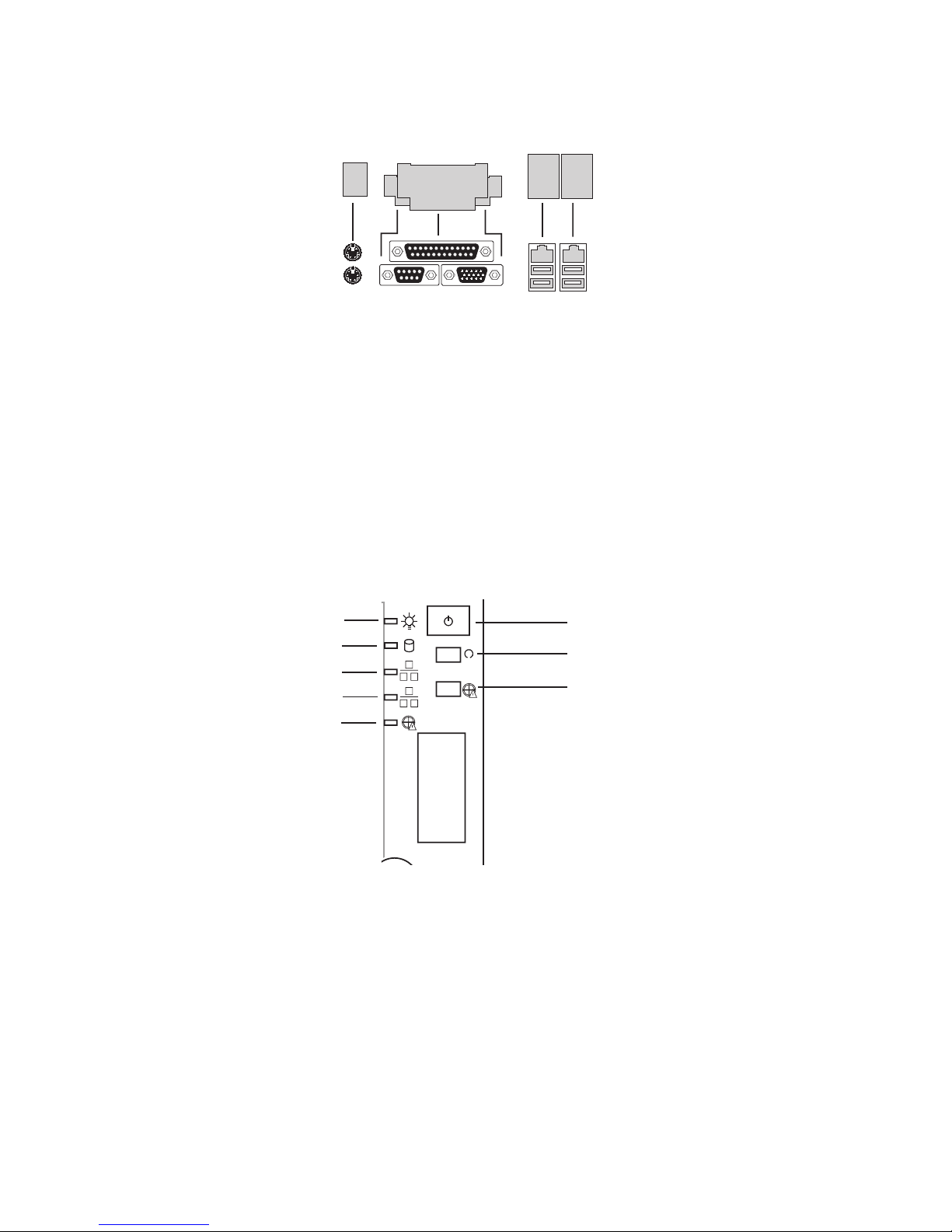
Rear Connectors
Figure 1. Rear connectors
A. PS/2-Mouse F. NIC 1
B. PS/2-Keyboard G. NIC 2
C. Parallel port (Parallelport) H.
USB-Connector 1
D. Serial port A (Serieller Port A) I.
USB-Connector 2
E. VGA port
Powering up the system
At the front of the case, you can find the neccessary controls like power button, reset button and the
HDD Leds. Press the power button one time briefly in order to boot the server.
Figure 2. The Controls
A.
Power switch
E.
NIC1 LED
B.
Reset switch
F.
NIC2 LED
C.
Disable Fan Warning
G.
HDD LED
D.
Fan Warning LED
H.
Power LED
7MAXDATA PLATINUM 220 Server
2 Server Description
This chapter briefly describes the main features of Intel® Server Board S875WP1-E.
Table 1 summarizes the major features of the desktop board.
Table 1. Server Board Features
Feature Description
Processors Support for an Intel® Pentium® 4 processor in an mPGA478 package with
an 800/533/400 MHz system bus
Memory • Four 184-pin DDR SDRAM Dual Inline Memory Module (DIMM)
sockets.
• Support for up to 4 GB Unbuffered ECC system memory.
• Support for single-sided or double-sided DIMMs (DDR266/333/400).
Chipset Intel® 875P Chipset, consisting of:
• Intel® 82875P Memory Controller Hub (MCH).
• Intel® 82801EB I/O Controller Hub (ICH5-R) with support for up to
six High-Speed Universal Serial Bus 2.0 (USB 2.0) ports.
• Intel® 82802AC 8 megabit Firmware Hub (FWH).
I/O Control SMSC LPC47M172 super I/O controller:
Peripheral Interfaces • Four external USB ports on the back panel with an additional
internal header, which provides support for an optional two USB
ports for front panel support (total possible six USB ports).
• One serial port and one serial header.
• One parallel port.
• Two IDE interfaces with ATA-66/100 support.
• Two Serial ATA connectors.
• One floppy drive interface with support for one drive.
• PS/2 keyboard and mouse ports.
LAN • One Intel® 82562ET 10/100 Fast Ethernet Controller.
• One Intel® 82547EI Gigabit Ethernet Controller.
Expansion CapabilitiesOne independent PCI bus (32-Bit/33 MHz, 5V) with three PCI connectors
and two embedded devices:
• 2D/3D graphics controller – ATI Rage XL Video Controller with 8 MB
of SDRAM.
• Serial ATA: SATA-150 controller, Promise Technology PDC20319.
• Accelerated Graphics Port (AGP) connector providing AGP 8x
support.
continued
8 Server Description
9MAXDATA PLATINUM 220 Server
Table 1. Server Board Features (continued)
BIOS Intel®/AMI BIOS with support for:
• Advanced Configuration and Power Interface (ACPI).
• 8 megabit symmetrical flash memory.
• Support for SMBIOS.
• Intel® Rapid BIOS Boot.
• Intel® Express BIOS Update.
Power Management Support for ACPI:
• Suspend to RAM (STR).
• Wake on USB, PCI, RS-232, PS/2, LAN, and front panel.
Hardware Management Hardware monitor with:
• Four fan sensing inputs used to monitor fan activity.
• Remote diode temperature sensing.
• Intel® Precision Cooling Technology fan speed control that automatically adjusts chassis fan speeds Based on system temperature.
• Voltage sensing to detect out of range values.
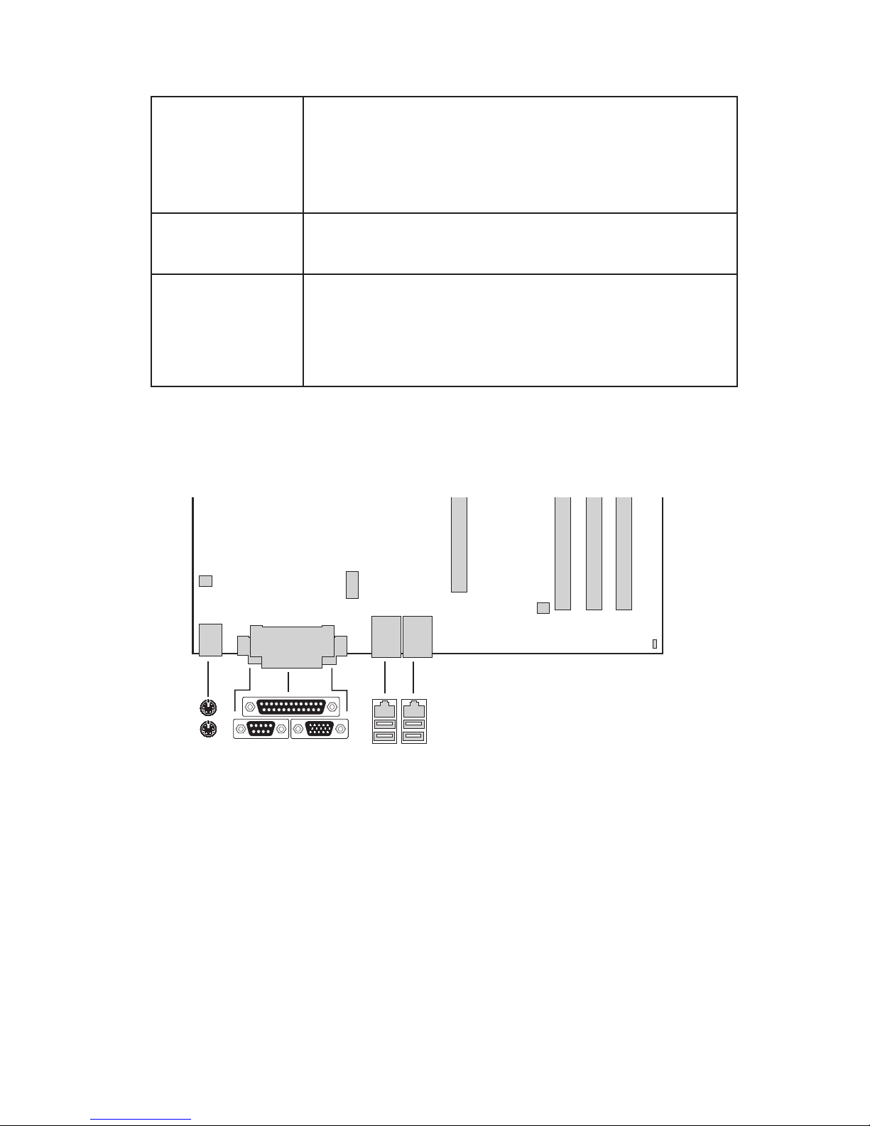
Back Panel Connectors
The back panel connectors are color-coded in compliance with PC 99 recommendations.
Figure 3. Back Panel Connectors
A. PS/2 mouse F.
NIC 1 (1 GB)
B. PS/2 keyboard G.
NIC 2 (10/100 MB)
C. Parallel port H. USB ports 1 and 2
D. Serial port A I. USB ports 3 and 4
E. Video port
9MAXDATA PLATINUM 220 Server
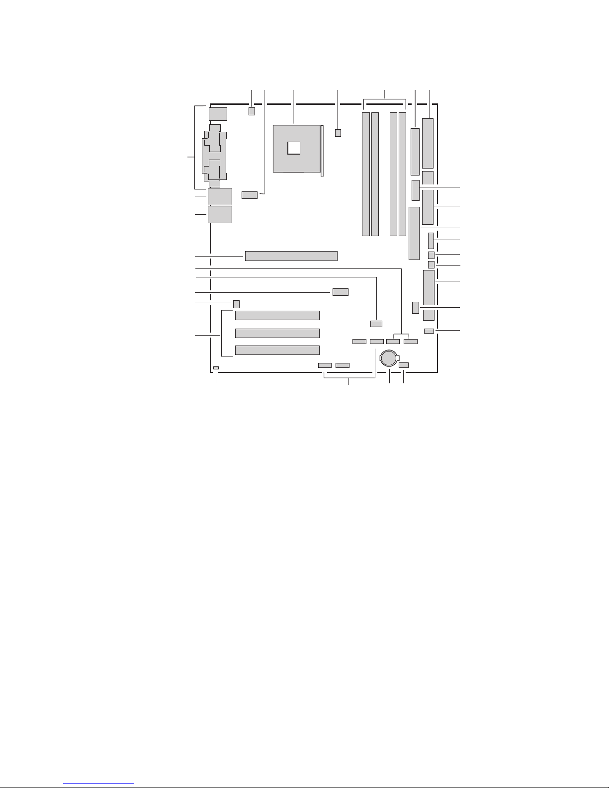
Server Board Connector and Component Locations
�
Figure 4. Server Board Components
A.
System Fan 4 Header
O.
BIOS Configuration Jumper (J8J2)
B.
+12V CPU Power Connector
P.
SCSI LED Header
C.
Processor Socket
Q.
Hot Swap Backplane Header
D.
CPU Fan
S.
SATA-A1 through SATA-A4 Connector
(S875WP1LX only, from left to right:
SATA-A4, SATA-A2, SATA-A3, SATA-A1)
E.
DIMM Sockets
T.
Chassis Intrusion Header
F.
Main Power Connector
U.
PCI 32/33 Slots 1 – 3
(slots numbered from top to bottom)
G.
Floppy Drive Connector
V.
System Fan 3 Header
H.
Auxiliary Power Connector
W.
Front Panel USB Header
I.
Primary IDE Connector
X.
Clear CMOS Jumper J8G1
J.
Secondary IDE Connector
Y.
SATA-B1 and SATA-B2 Connectors
(slots numbered from left to right)
K.
Serial B Header
Z.
AGP Connector
L.
System Fan 1 Header
AA.
NIC2 (10/100 MB)
M.
System Fan 2 Header
BB.
NIC1 (1 GB)
N.
Front Panel Connector
CC.
Back Panel I/O Ports

10 Server Description
11MAXDATA PLATINUM 220 Server
Processor
The S875WP1-E server board supports a single Intel® Pentium® 4 processor with an mPGA478 socket.
The processor connects to the server board through the mPGA478 socket. The Intel® Pentium® 4
processor can be removed and replaced to accommodate a supported higher speed processor.
The server board S875WP1-E supports the following processors.
Table 2. Supported Processors
Type Designation System Bus L2 Cache
Size
Pentium® 4 processor with HyperThreading (HT) Technology
2.40, 2.60, 2.80, and 3.0 GHz 800 MHz
512 KB
3.06 GHz 533 MHz
512 KB
Pentium® 4 processor 2.0, 2.26, 2.4B, 2.53, 2.66 and
2.80 GHz
533 MHz
512 KB
2.0, 2.4 GHz 400 MHz
512 KB
Memory
The S875WP1-E server board contains four 184-pin DIMM sockets and supports up to four DDR
SDRAM DIMMs. The minimum supported memory configuration is 128 MB and the maximum
configurable memory size is 4 GB with stacked unbuffered DDR266/333/400 ECC DIMMs.
Supported memory configurations are as follows:
Up to four dual-channel 184-pin Double Data Rate (DDR) SDRAM DIMMs connectors with gold-plated
contacts. Supported memory configuration are:
1. DDR400: To run DDR400 memory at full speed requires an Intel® Pentium® 4 processor with
800 MHz front side bus (FSB) frequency.
2. DDR333: To run DDR333 memory at full speed requires an Intel® Pentium® 4 processor with
533 MHz FSB frequency. DDR333 memory will run at 320 MHz frequency when using an
Intel® Pentium® 4 processor with 800 MHz FSB frequency.
3. DDR266: DDR266 memory may only be used with an Intel® Pentium® 4 processor with
400 MHz or 533 MHz FSB frequency only.
Support for:
1. Single-channel memory.
2. Unbuffered, single or double-sided DIMMs.
3. Serial Presence Detect (SPD) memory only.
4. Support for Suspend to RAM (STR), S3 ACPI state.
5. ECC and non-ECC RAM.
6. 2.5V memory.
Support for 128 MB, 256 MB, and 512 MB memory technologies for the following memory configurations:
1. Up to 1.0 GB utilizing 128 MB technology.
2. Up to 2.0 GB utilizing 256 MB technology.
3. Up to 4.0 GB utilizing 512 MB technology.
Only DIMMs tested and qualified by Intel® or a designated memory test vendor will be supported
on the board. Note that all DIMMs are supported by design, but only fully qualified DIMMs will be
supported. Mixed mode DDR DS-DIMMs (x8 and x16 on the same DIMM) is not supported.
 Loading...