

Page 1

MAXDATA PLATINUM 2210R Server Chassis
User‘s Manual
Page 2

Contents
Page 3

3
Tools and Supplies Needed
Warnings and Cautions
Page 4

Figures
Tables
Page 5

A.
J.
Tape drive bay (tape drive available from others)
Page 6
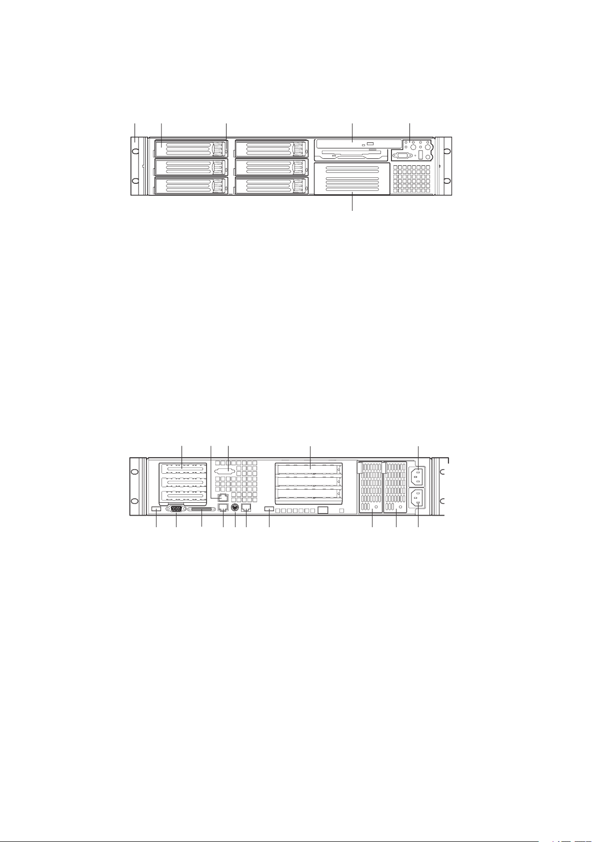
To access the system controls and peripherals when a front bezel is installed, grasp the
A.
Tape drive bay (tape drive not included)
J.
AC power input (primary)*
AC power input (redundant)*
Video connector
*480 Watt redundant power supply shown. Your power supply may be different.
Page 7
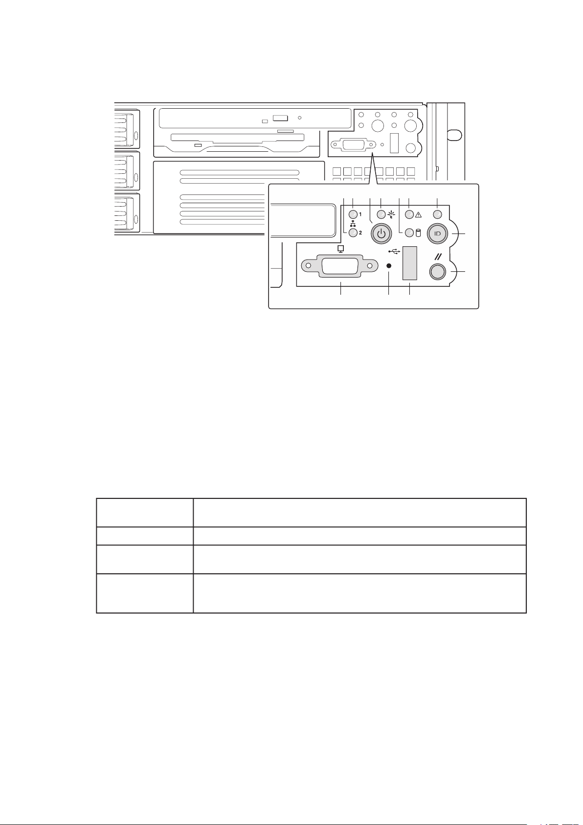
J.
Video Connector
Table 1. Control Button Functions
Toggles the system power on/off. Or sleep button for ACPI compliant operating
Toggles on/off the front panel ID LED and the baseboard ID LED. The baseboard
ver you’re working on from behind a rack of servers.
Page 8
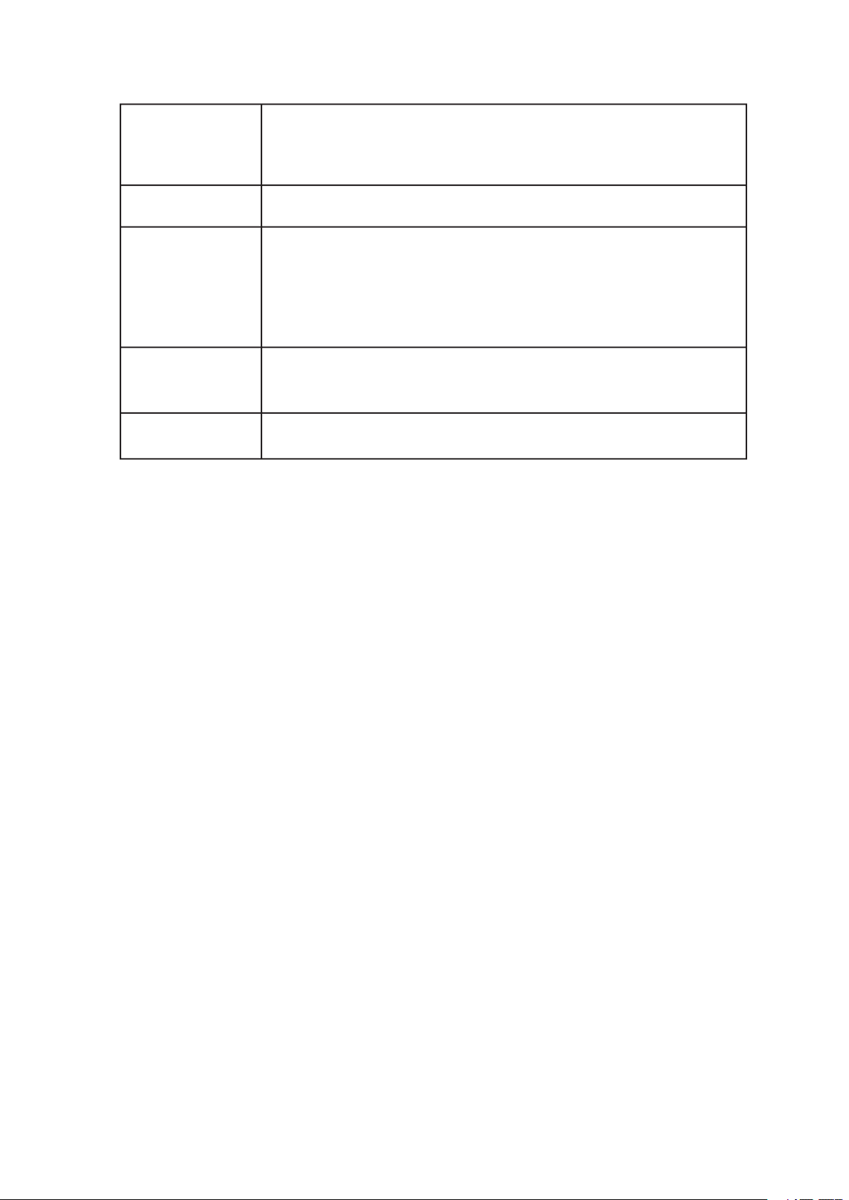
Table 2. LED Indicator Status
which it is connected.
The Amber status takes precedence over the Green status. When the Amber LED is
Also off when the system is powered off or in a sleep state.
The Power LED sleep indication is maintained on standby by the chipset. If the system
Page 9
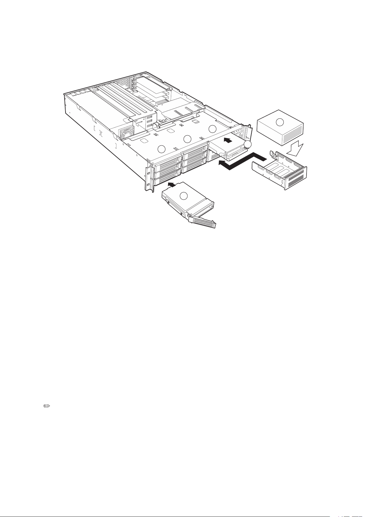
The chassis provides external bays for peripherals that can be purchased separately and
added to the system. The following describes the available options.
A.
Tape drive
The chassis ships with four drive carriers for mounting SCSI hard drives in the hard drive
bays. The SCSI hard drives are hot swappable. When a drive fails, the SCSI backplane detects
the failure, reports it, and powers down the failed drive. The drive fault LED becomes a
continuous amber light. After the failed drive is removed and a new drive is inserted, there is
a short wait before power is applied to the drive and the drive fault LED becomes a random
blinking green light.
Page 10

The flex bay can be used with either the optional DVD/FDD module, CD-ROM/FDD module,
The DVD/CD-ROM/FDD module may only be inserted or removed from the flex bay when
The power supply consists of the power supply bay and one power supply module. A second
The power supply operates within the following voltage ranges and is rated as follows:
The power subsystem supports implementation of remote management features including
The power supply consists of the power supply; no modules are available. The power supply
The power subsystem supports implementation of remote management features including
The chassis includes three 60-mm non-hot-swappable system fans for cooling the processor(s),
To help prevent unauthorized access to the system’s peripherals and control panel, install
To unlock the bezel, insert the key in the lock and turn the lock counterclockwise until it
To lock the bezel, insert the key in the lock. Turn the lock clockwise until it stops (about a
Page 11
Your chassis comes equipped with a rack mount kit that can be configured for front-mount,
Anchor The Equipment Rack: The equipment rack must be anchored to an unmovable
support to prevent it from falling over when one or more servers are extended in front of it
on slide assemblies. The equipment rack must be installed according to the manufacturer’s
instructions. You must also consider the weight of any other device installed in the rack.
Main AC Power Disconnect: You are responsible for installing an AC power disconnect for
the entire rack unit. This main disconnect must be readily accessible, and it must be labeled
as controlling power to the entire unit, not just to the server(s).
Grounding The Rack Installation: To avoid the potential for an electrical shock hazard, you
must include a third wire safety grounding conductor with the rack installation. If server power
cords are plugged into AC outlets that are part of the rack, then you must provide proper
grounding for the rack itself. If server power cords are plugged into wall AC outlets, the safety
grounding conductor in each power cord provides proper grounding only for the server. You
must provide additional, proper grounding for the rack and other devices installed in it.
Over Current Protection: The server is designed for an AC line voltage source with up to 20
amperes of over current protection. If the power system for the equipment rack is installed
on a branch circuit with more than 20 amperes of protection, you must provide supplemental
protection for the server. If more than one server is installed in the rack, the power source
for each server must be from a separate branch circuit.
Temperature:
The operating temperature of the server, when installed in an equipment rack,
Ventilation:
The equipment rack must provide sufficient airflow to the front of the server
An extra 500 BTU/hr over many systems would translate into a large error calculating air
Page 12

Page 13
This chapter describes how to replace components in your server after it has been set up.
All references to left, right, front and rear are based on the reader facing the front of the
chassis.
Antistatic wrist strap (recommended)
Turn off all peripheral devices connected to the system.
Turn off the system by pressing the power button on the front of the system. Then
Attach a wrist strap to a chassis ground of the system – any unpainted metal surface –
These warnings and cautions apply whenever you remove the chassis cover to access
components inside the server. Only a technically quali ed person should integrate and
con gure the server.
WARNING
valent type recommended by the manufacturer. Dispose of used batteries according to the
Page 14
Working Inside Your Server
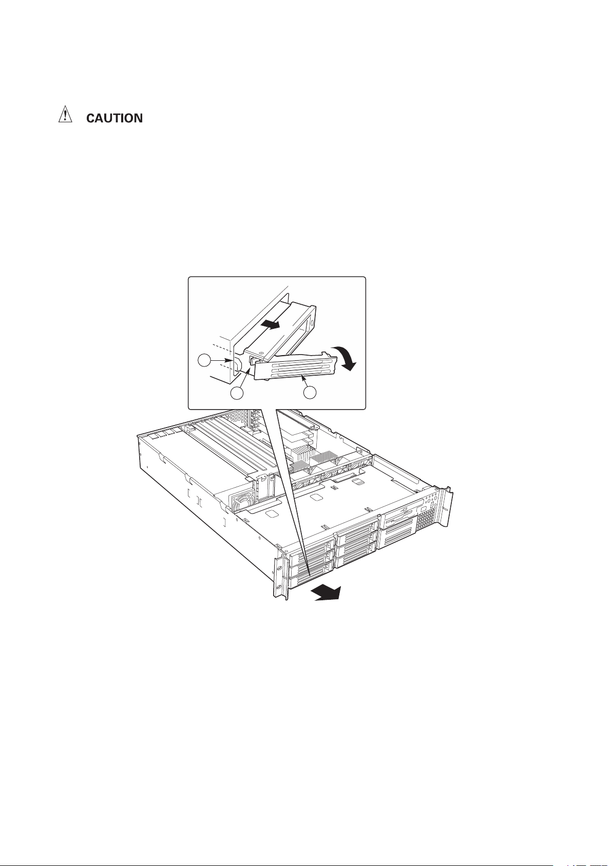
To allow proper airflow and cooling during operation, all drive bays must contain either a
Page 15
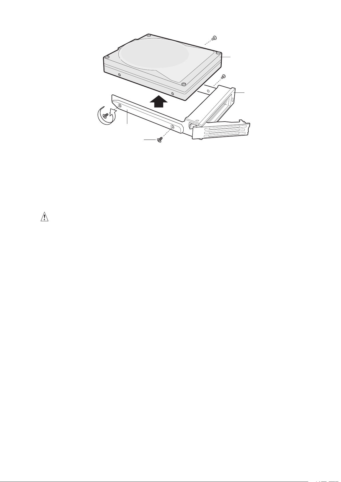
Figure 7. Removing a Hard Drive from a Carrier
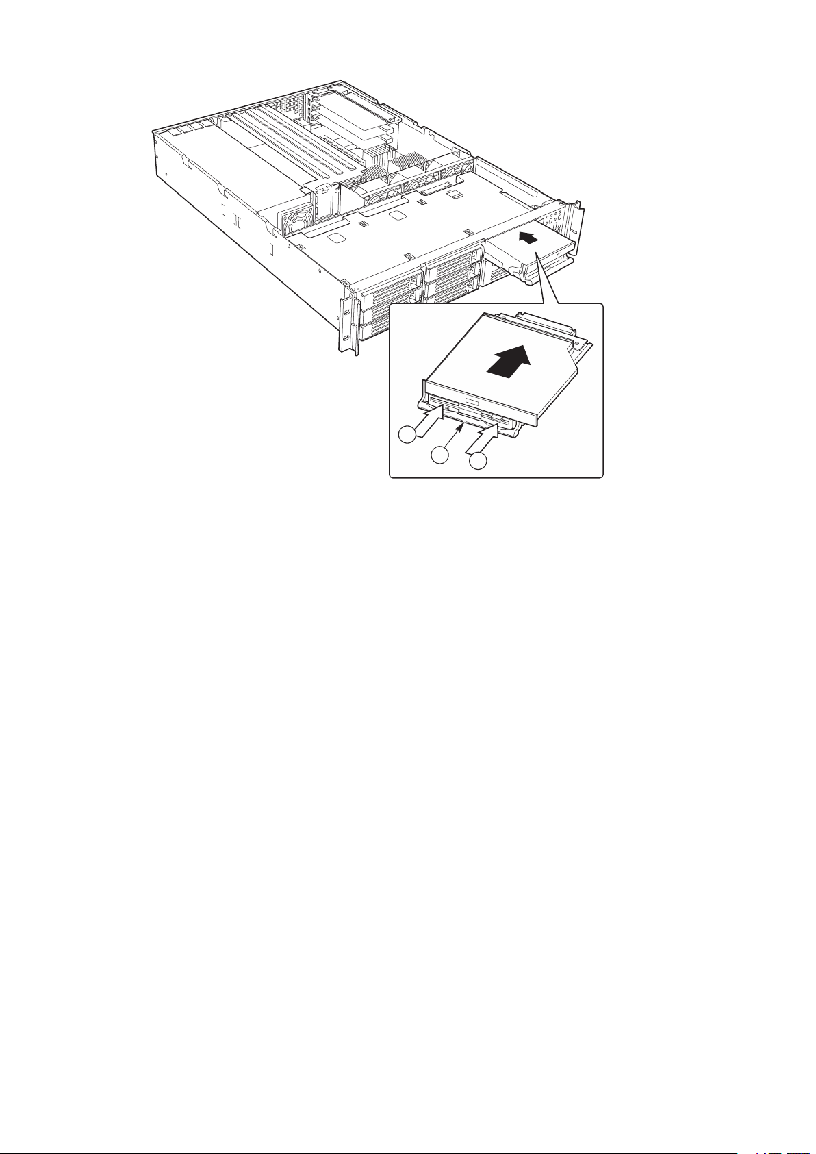
A DVD/CD-ROM drive/FDD module is NOT hot swappable. Before replacing it, you must
you first pull, resistance will be high until the connector disengages.)
With your thumbs positioned above the handle bar indentations (B), push the module in
Page 16
Working Inside Your Server
Page 17
Page 18
Working Inside Your Server
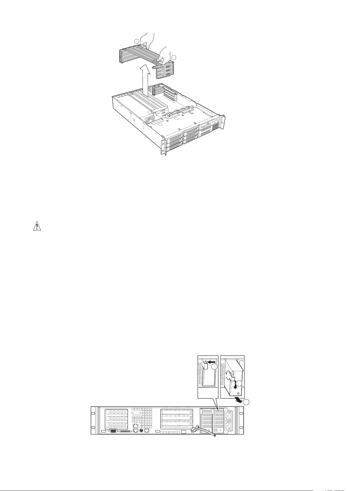
The 500 Watt redundant power supply system consists of the power supply bay and either
one or two power supply modules. The optional second module provides a redundant, 1+1
system.
When the module is nearly all of the way in, the handle will rotate up. At this time, push
The power supply module is now functional and the power supply fault indicator should
Page 19
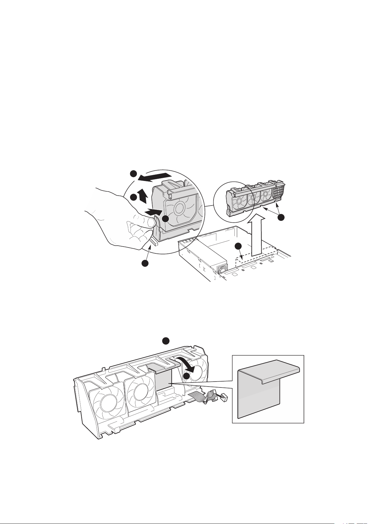
At the end of the fan module closest to the chassis centerline, push on the tab to release
While pushing on the tab, lift up on the module to clear the retention stub.
Page 20
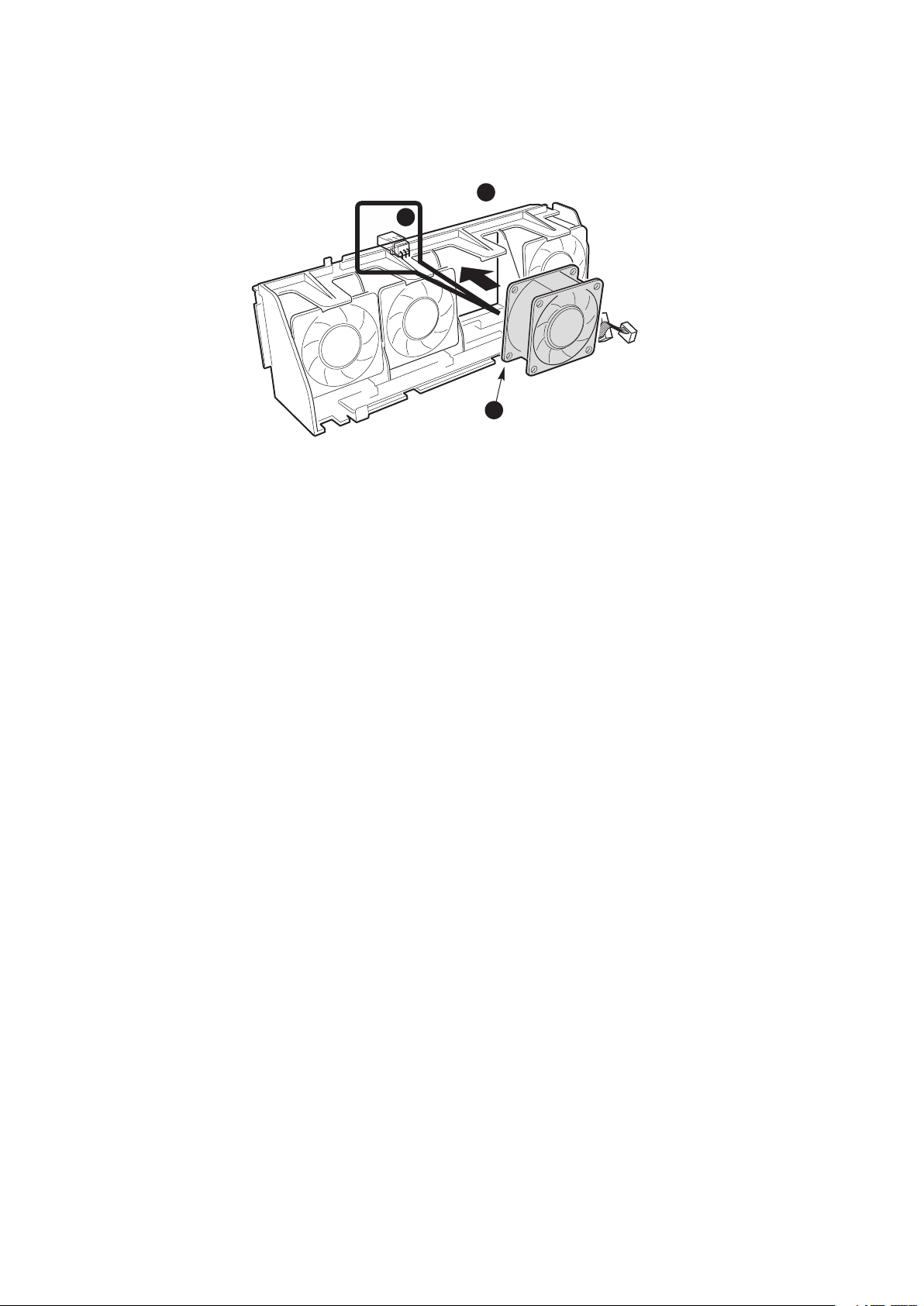
Working Inside Your Server
Align the holes in the fan module with the raised tabs on the chassis and lower the fan
Page 21
WARNING
You must adhere to the assembly instructions in this guide to ensure and maintain
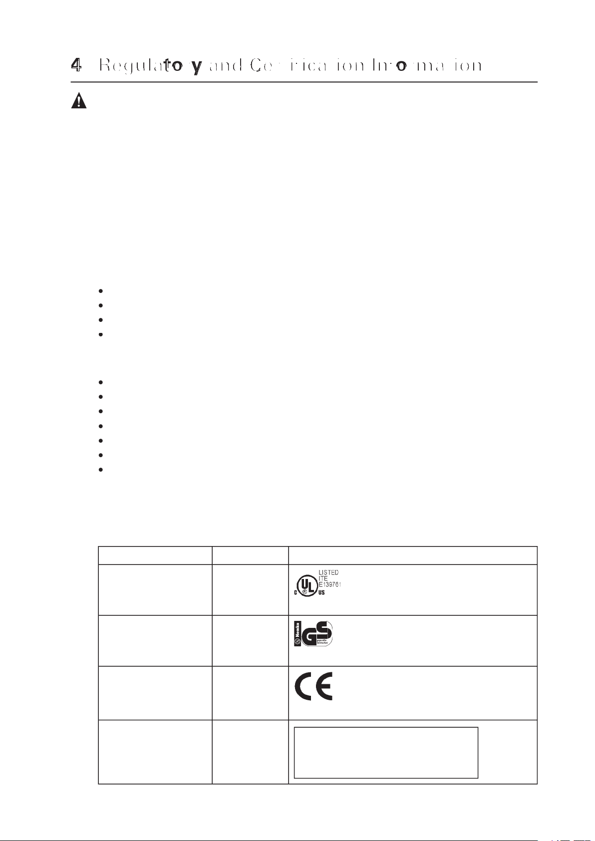
The MAXDATA PLATINUM 2210R chassis subassembly, when correctly integrated per this
The MAXDATA PLATINUM 2210R server chassis will be marked with the following re-
This device complies with Part 15 of the FCC Rules. Operation
Page 22

This device complies with Part 15 of the FCC Rules. Operation is subject to the following two
This equipment has been tested and found to comply with the limits for a Class A digital
Any changes or modifications not expressly approved by the grantee of this device could
void the user’s authority to operate the equipment. The customer is responsible for ensuring
with FCC Class A or B limits may be attached to this computer product. Operation with
All cables used to connect to peripherals must be shielded and grounded. Operation with
This product has been tested in accordance too, and complies with the Low Voltage Directive
(73/23/EEC) and EMC Directive (89/336/EEC). The product has been marked with the CE
Mark to illustrate its compliance.
 Loading...