

Maxdata 7200IRM5 user manual

MAXDATA PLATINUM 7200 IR M5
User’s Manual

2 3MAXDATA PLATINUM 7200 IR M5Contents

Contents
1 Safety Information 7
Safety Warnings and Cautions ................................................................................................................7
Intended Application Uses ......................................................................................................................7
General Warnings ....................................................................................................................................8
Place Battery Marking ........................................................................................................................8
Site Selection ..........................................................................................................................................9
Equipment Handling Practices ................................................................................................................9
Power Cord Warnings ...........................................................................................................................10
System Access Warnings .....................................................................................................................10
Rack Mount Warnings ...........................................................................................................................11
Electrostatic Discharge (ESD) ................................................................................................................11
Other Hazards .......................................................................................................................................11
Battery Replacement ........................................................................................................................11
Cooling and Airflow ..........................................................................................................................11
Laser Peripherals or Devices ............................................................................................................ 12
2 Platform Description 13
Platform Features ..................................................................................................................................14
Platform Front .......................................................................................................................................15
Standard Control Panel ..........................................................................................................................16
Local Control Panel ................................................................................................................................18
Platform Rear ........................................................................................................................................20
Processors .............................................................................................................................................21
Plug-in Voltage Regulator Module (VRM) Converters ...........................................................................21
System Memory ....................................................................................................................................21
Available Memory Configurations ....................................................................................................22
Power Subsystem .................................................................................................................................24
Power Supply Modules ....................................................................................................................24
Cooling Subsystem ...............................................................................................................................26
Hot-swap PCI Slots ...............................................................................................................................26
Peripherals .............................................................................................................................................27
Hot-Swap SCSI Hard Disk Drive Support .........................................................................................27
Removable Media Drive Bay Support ..............................................................................................27
5 ¼-inch Half-height Drive Bay .........................................................................................................27
Platform Board Set ................................................................................................................................28
Main Board ............................................................................................................................................ 29
RAID Support ........................................................................................................................................31
Memory Board ......................................................................................................................................32
3 Starting Up and Shutting Down the Server 33
Plugging the Server into AC Power .......................................................................................................33
Powering On the Server ........................................................................................................................33
Shutting Down the Server .....................................................................................................................34
4 Server Platform Utilities 35
BIOS Setup Utility .................................................................................................................................35
BIOS Setup Utility Page Layout .............................................................................................................35
Keyboard Commands ............................................................................................................................ 36
Console Redirection ..............................................................................................................................37
Serial Configuration Settings .................................................................................................................37
Keystroke Mappings ..............................................................................................................................38

Setup Alias Keys ....................................................................................................................................38
Limitations .............................................................................................................................................38
Interface to Server Management ..........................................................................................................38
Sample Setup for Console Redirection .................................................................................................38
Server Configuration .........................................................................................................................38
Console Configuration ......................................................................................................................39
LSI Logic MPT SCSI Utility ....................................................................................................................40
System Configuration Wizard (SCW) .....................................................................................................42
Starting the System Configuration Wizard ............................................................................................43
Using the Server Configuration Wizard Option .....................................................................................43
Configuring Channels ............................................................................................................................45
LAN Channel Configuration Screen 1 - LAN IP Setup ...........................................................................45
LAN Channel Configuration Screen 2 - Server Management and Serial Over LAN Setup ....................47
LAN Channel Configuration Screen 3 - LAN Alerting Setup ..................................................................48
Configuring the Serial/Modem Channel ................................................................................................49
Serial/Modem Configuration Screen 1 - Modem Setup ........................................................................49
Serial/Modem Configuration Screen 2 -
Configuring Remote Server Management Options for a Serial / Modem Connection ..........................50
Serial/Modem Configuration Screen 3 - Configuring Alerting over a Serial/Modem Connection ..........51
Select Users to Configure Screen .........................................................................................................52
Configure Users Screen ........................................................................................................................52
Configuring the Advanced Features ......................................................................................................54
Advanced Features Configuration Screen 1: SNMP, KVM, Telnet ........................................................54
SNMP Settings ................................................................................................................................. 54
KVM Settings ...................................................................................................................................54
Telnet Settings .................................................................................................................................54
Advanced Features Configuration Screen 2: HTTP Settings .................................................................55
Advanced Features Configuration Screen 3: SMTP Alert Settings .......................................................55
Saving the Configuration to a Disk ........................................................................................................56
Saving the Configuration to the Server .................................................................................................56
5 User Serviceable Platform Components 57
Tools and Supplies Needed ...................................................................................................................57
Removing and Installing the Top Cover .................................................................................................57
Removing the Top Cover ..................................................................................................................58
Installing the Top Cover ....................................................................................................................58
Hot-swapping a System Fan Assembly .................................................................................................59
Hot-swapping Hard Disk Drives ............................................................................................................60
Determining Drive Status .................................................................................................................60
Removing a Hard Disk Drive ............................................................................................................61
Mounting a Hard Disk Drive in a Carrier ...........................................................................................61
Installing a Hard Disk Drive Assembly ..............................................................................................61
Hot-swapping Power Supplies ..............................................................................................................62
Removing a Power Supply ...............................................................................................................62
Installing a Power Supply .................................................................................................................62
Installing and Removing PCI Cards .......................................................................................................63
Removing Hot-plug PCI Card with Operating System Hot-Plug Interface ........................................63
Removing Hot-plug PCI Card with Hardware Hot-Plug Interface ..................................................... 64
Installing a Hot-plug PCI Add-in Card ................................................................................................65
Removing a Non-Hot-Plug PCI Card .................................................................................................66
Installing a Non-Hot-Plug PCI Card ...................................................................................................66
Installing and Removing the Fibre Channel Module ..............................................................................67
Removing the Fibre Channel Module ............................................................................................... 67
Installing the Fibre Channel Module ................................................................................................. 68
4 5MAXDATA PLATINUM 7200 IR M5Contents

Installing and Removing Memory Boards .............................................................................................68
Removing Memory Board Air Baffle ................................................................................................69
Installing Memory Board Air Baffle ..................................................................................................69
Hot Removal of a Memory Board .....................................................................................................70
Hot Insertion of a Memory Board .....................................................................................................71
Cold Removal of Memory Board ......................................................................................................71
Cold Insertion of a Memory Board ...................................................................................................71
Installing and Removing DIMMs ...........................................................................................................72
Rules for Adding Memory ................................................................................................................72
Installing DIMMs ..............................................................................................................................73
Removing DIMMs ............................................................................................................................74
6 Replacing the CMOS Battery 75
7 Regulatory and Integration Information 77
Product Regulatory Compliance ............................................................................................................77
Product Safety Compliance ..............................................................................................................77
Product EMC Compliance .....................................................................................................................77
Product Regulatory Compliance Markings ............................................................................................77
Electromagnetic Compatibility Notices .................................................................................................77
Europe (CE Declaration of Conformity) ............................................................................................77

Figures
1. PLATINUM 7200 IR Server Front View ...........................................................................................13
2. Front Components ..........................................................................................................................15
3. Front Panel Controls and Indicators ................................................................................................16
4. Local Control Panel .........................................................................................................................18
5. Rear Platform Features ...................................................................................................................20
6. Power Supply Indicators ..................................................................................................................25
7. Hard Disk Drive Carrier .................................................................................................................... 27
8. Main Board Component Locations .................................................................................................. 29
9. Hot-Plug Memory Board LEDs and Buttons ....................................................................................32
10. Removing the Top Cover ................................................................................................................58
11. System Fan Location and Removal .................................................................................................59
12. Hard Disk Drive Carrier ....................................................................................................................60
13. Removing the Battery .....................................................................................................................76
Tables
1. Safety Warnings and Cautions ..........................................................................................................7
2. Chassis Feature Summary ..............................................................................................................14
3. Front Components ..........................................................................................................................15
4. Front Panel Controls and Indicators ................................................................................................16
5. Local Control Panel .........................................................................................................................18
6. Rear Platform Features ...................................................................................................................20
7. Power Supply Indicators ..................................................................................................................25
8. Power Indicator ...............................................................................................................................26
9. Attention Indicator ........................................................................................................................... 26
10. Hard Disk Drive Carrier ....................................................................................................................27
11. Main Board Component Locations ..................................................................................................30
12. Hot-Plug Memory Board LEDs and Buttons ....................................................................................32
13. BIOS Setup Utility Page Layout .......................................................................................................35
14. BIOS Setup: Keyboard Commands .................................................................................................36
15. Hard Disk Drive Carrier ....................................................................................................................60
16. Product Certification Markings ........................................................................................................77
6 MFMAXDATA PLATINUM 7200 IR M5Contents
1 Safety Information
This document applies to MAXDATA PLATINUM Server Boards, MAXDATA PLATINUM Server Chassis
(pedestal and rack-mount) and installed peripherals. To reduce the risk of bodily injury, electrical shock,
fire, and equipment damage, read this document and observe all warnings and precautions in this
guide before installing or maintaining your MAXDATA PLATINUM server product.
In the event of a conflict between the information in this document and information provided with the
product or on the website for a particular product, the product documentation takes precedence.
Your server should be integrated and serviced only by technically qualified persons.
You must adhere to the guidelines in this guide and the assembly instructions in your server manuals
to ensure and maintain compliance with existing product certifications and approvals. Use only the
described, regulated components specified in this guide. Use of other products/components will void
the UL Listing and other regulatory approvals of the product, and may result in noncompliance with
product regulations in the region(s) in which the product is sold.
Safety Warnings and Cautions
To avoid personal injury or property damage, before you begin installing the product, read, observe,
and adhere to all of the following safety instructions and information. The following safety symbols
may be used throughout the documentation and may be marked on the product and/or the product
packaging.
Table 1. Safety Warnings and Cautions
Indicates potential hazard if indicated information is ignored
Indicates shock hazard that results in serious injury or death if safety
instructions are not followed
Indicates hot components and surfaces
Indicates electrostatic discharge cautions
Indicates do not touch fan blades, may result in injury
Indicates to unplug all AC power cord(s) to disconnect AC power
Intended Application Uses
This product was evaluated as Information Technology Equipment (ITE), which may be installed in
offices, schools, computer rooms, and similar commercial type locations. The suitability of this product
for other product categories and environments (such as medical, industrial, residential, alarm systems,
and test equipment), other than an ITE application, may require further evaluation.
7MAXDATA PLATINUM 7200 IR M5
General Warnings
The power supply in this product contains no user-serviceable parts. There may be
more than one supply in this product. Refer servicing only to qualified personnel.
Do not attempt to modify or use the supplied AC power cord if it is not the exact type
required. A product with more than one power supply will have a separate AC cord
for each supply.
The DC push-button on/off switch on the front panel does not turn off system AC
power. To remove power from the system, you must unplug each AC power cord
from the wall outlet or power supply.
Ensure that the system is disconnected from its power source and from all telecommunication links, networks, and modem lines whenever the chassis cover is to be
removed. This may require disconnecting multiple power cords. Do not operate the
system with the cover removed.
A microprocessor and heat sink may be hot if the system has been running. Also,
there may be sharp pins and edges on some board and chassis parts. Contact should
be made with care. Consider wearing protective gloves.
Danger of explosion if the battery is incorrectly replaced. Replace only with the same
or equivalent type recommended by the equipment manufacturer. Discard used
batteries according to manufacturer’s instructions.
Depending on the weight of the product, two people together should lift it.
The system is designed to operate in a typical office environment. Choose a site that
is:
• Clean and free of airborne particles (other than normal room dust).
• Well ventilated and away from sources of heat including direct sunlight.
• Away from sources of vibration or physical shock.
• Isolated from strong electromagnetic fields produced by electrical devices.
• In regions that are susceptible to electrical storms, we recommend you plug your
system into a surge suppresser and disconnect telecommunication lines to your
modem during an electrical storm.
• Provided with a properly grounded wall outlet.
• Provided with sufficient space to access the power supply cords, because they
serve as the product’s main power disconnect.
Place Battery Marking
There is insufficient space on this server board to provide instructions for replacing and disposing of
the battery. For system safety certification, the following statement or equivalent statement may be
required to be placed permanently and legibly on the chassis near the battery.
CAUTION
Risk of explosion if battery is incorrectly replaced.
Replace with only the same or equivalent type recommended by the manufacturer. Dispose of used
batteries according to the manufacturer’s instructions.
8 Safety Information

Site Selection
The system is designed to operate in a typical office environment. Choose a site that is:
• Clean, dry, and free of airborne particles (other than normal room dust).
• Well-ventilated and away from sources of heat including direct sunlight and radiators.
• Away from sources of vibration or physical shock.
• Isolated from strong electromagnetic fields produced by electrical devices.
• In regions that are susceptible to electrical storms, we recommend you plug your system
into a surge suppresser and disconnect telecommunication lines to your modem during an
electrical storm.
• Provided with a properly grounded wall outlet.
• Provided with sufficient space to access the power supply cord(s), because they serve as the
product’s main power disconnect.
Equipment Handling Practices
Reduce the risk of personal injury or equipment damage:
• Conform to local occupational health and safety requirements when moving and lifting
equipment.
• Use mechanical assistance or other suitable assistance when moving and lifting equipment.
• To reduce the weight for easier handling, remove any easily detachable components.
CAUTION
The power button, indicated by the stand-by power marking, DOES NOT completely turn off the system
AC power, 5 V standby power is active whenever the system is plugged in. To remove power from
system, you must unplug the AC power cord from the wall outlet. Your system may use more than
one AC power cord. Make sure all AC power cords are unplugged. Make sure the AC power cord(s)
is/are unplugged before you open the chassis, or add or remove any non hot-plug components.
Do not attempt to modify or use an AC power cord if it is not the exact type required. A separate AC
cord is required for each system power supply.
Some power supplies in MAXDATA PLATINUM Servers use Neutral Pole Fusing. To avoid risk of
shock use CAUTION when working with power supplies that use Neutral Pole Fusing.
The power supply in this product contains no user-serviceable parts. Do not open the power supply.
Hazardous voltage, current and energy levels are present inside the power supply. Return to
manufacturer for servicing.
When replacing a hot-plug power supply, unplug the power cord to the power supply being replaced
before removing it from the server.
To avoid risk of electric shock, turn off the server and disconnect the power cord, telecommunications
systems, networks, and modems attached to the server before opening it.
9MAXDATA PLATINUM 7200 IR M5
Power Cord Warnings
If an AC power cord was not provided with your product, purchase one that is approved for use in
your country.
CAUTION
To avoid electrical shock or fire, check the power cord(s) that will be used with the product as
follows:
• Do not attempt to modify or use the AC power cord(s) if they are not the exact type required to
fit into the grounded electrical outlets
• The power cord(s) must meet the following criteria:
- The power cord must have an electrical rating that is greater than that of the electrical
current rating marked on the product.
- The power cord must have safety ground pin or contact that is suitable for the electrical
outlet.
• The power supply cord(s) is/are the main disconnect device to AC power. The socket outlet(s)
must be near the equipment and readily accessible for disconnection.
• The power supply cord(s) must be plugged into socket-outlet(s) that is /are provided with a
suitable earth ground.
System Access Warnings
CAUTION
To avoid personal injury or property damage, the following safety instructions apply whenever accessing
the inside of the product:
• Turn off all peripheral devices connected to this product.
• Turn off the system by pressing the power button to off.
• Disconnect the AC power by unplugging all AC power cords from the system or wall outlet.
• Disconnect all cables and telecommunication lines that are connected to the system.
• Retain all screws or other fasteners when removing access cover(s). Upon completion of
accessing inside the product, refasten access cover with original screws or fasteners.
• Do not access the inside of the power supply. There are no serviceable parts in the power
supply. Return to manufacturer for servicing.
• Power down the server and disconnect all power cords before adding or replacing any non hotplug component.
• When replacing a hot-plug power supply, unplug the power cord to the power supply being
replaced before removing the power supply from the server.
CAUTION
If the server has been running, any installed processor(s) and heat sink(s) may be hot. Unless you
are adding or removing a hot-plug component, allow the system to cool before opening the covers.
To avoid the possibility of coming into contact with hot component(s) during a hot-plug installation,
be careful when removing or installing the hot-plug component(s).
CAUTION
To avoid injury do not contact moving fan blades. If your system is supplied with a guard over the
fan, do not operate the system without the fan guard in place.
10 Safety Information

Rack Mount Warnings
The equipment rack must be anchored to an unmovable support to prevent it from tipping when a
server or piece of equipment is extended from it. The equipment rack must be installed according to
the rack manufacturer’s instructions.
Install equipment in the rack from the bottom up, with the heaviest equipment at the bottom of the
rack.
Extend only one piece of equipment from the rack at a time.
You are responsible for installing a main power disconnect for the entire rack unit. This main disconnect
must be readily accessible, and it must be labeled as controlling power to the entire unit, not just to
the server(s).
To avoid risk of potential electric shock, a proper safety ground must be implemented for the rack
and each piece of equipment installed in it.
Electrostatic Discharge (ESD)
CAUTION
ESD can damage disk drives, boards, and other parts. We recommend that you perform all procedures
at an ESD workstation. If one is not available, provide some ESD protection by wearing an antistatic
wrist strap attached to chassis ground - any unpainted metal surface - on your server when handling
parts.
Always handle boards carefully. They can be extremely sensitive to ESD. Hold boards only by their
edges. After removing a board from its protective wrapper or from the server, place the board
component side up on a grounded, static free surface. Use a conductive foam pad if available but
not the board wrapper. Do not slide board over any surface
Other Hazards
Battery Replacement
CAUTION
There is the danger of explosion if the battery is incorrectly replaced. When replacing the battery, use
only the battery recommended by the equipment manufacturer.
Dispose of batteries according to local ordinances and regulations.
Do not attempt to recharge a battery.
Do not attempt to disassemble, puncture, or otherwise damage a battery.
Cooling and Airflow
CAUTION
Carefully route cables as directed to minimize airflow blockage and cooling problems. For proper
cooling and airflow, operate the system only with the chassis covers installed. Operating the system
without the covers in place can damage system parts. To install the covers:
1. Check first to make sure you have not left loose tools or parts inside the system.
2. Check that cables, add-in boards, and other components are properly installed.
3. Attach the covers to the chassis according to the product instructions.
11MAXDATA PLATINUM 7200 IR M5

Laser Peripherals or Devices
CAUTION
To avoid risk of radiation exposure and/or personal injury:
• Do not open the enclosure of any laser peripheral or device.
• Laser peripherals or devices are not user serviceable.
• Return to manufacturer for servicing.
12 Safety Information
2 Platform Description
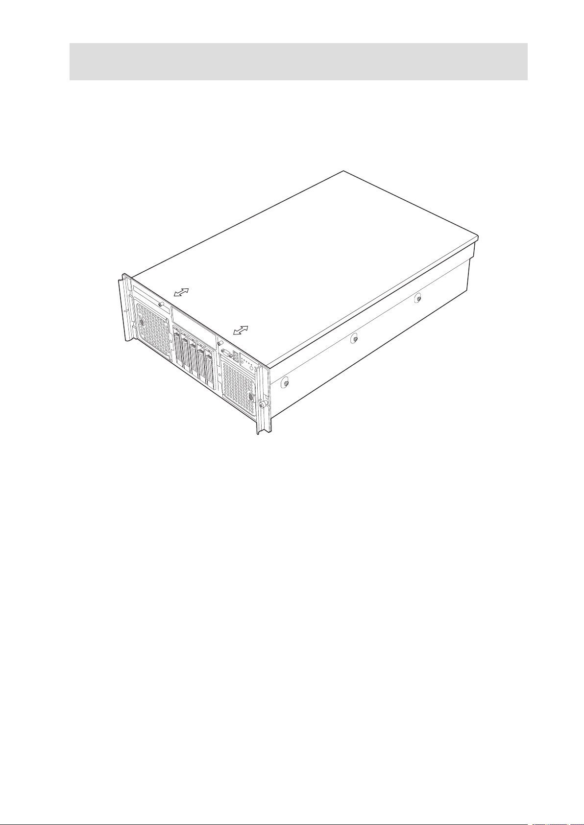
The PLATINUM 7200 IR Server is a compact, high-density, rack-mount system with support for one
to four Intel® Xeon™ processors and 64 GB of DDR2 400 MHz SDRAM memory. The system is based
on the PLATINUM 7200 IR Server Board using the Intel® E8501 chipset. The platform supports hot
plug PCI-X and PCI-Express add-in cards; hot-swap, redundant power supply modules; hot swap,
redundant cooling fans, hot-plug memory with RAS features, and hot-swap hard disk drives. The
server platform is shown below.
Figure 1. PLATINUM 7200 IR Server Front View

Platform Features
The platform features are outlined in the following table.
Table 2. Chassis Feature Summary
Feature Description
Dimensions (4U rackmount platform)
Clearance
requirements
Configuration
flexibility/Scaleability
Serviceability • Front access to hot-swap hard disk drives
Availability • Four hot-plug PCI-Express slots
Manageability • Server Management support through the Management Module - Profes
Front control panel • System power button and LED
Height: 6.8 inches (173 mm)
Width: 17.6 inches (447 mm)
Depth: 27.8 inches (706 mm)
Weight of fully configured system: 90 lbs (40 kg)
• Front clearance: 3 inches (76 mm)
• Side clearance: 1 inch (25 mm)
• Rear clearance: 6 inches (152 mm)
• Support for one to four processors
• Support for at least two generations of processors
• Support for up to five Ultra 320 SCSI hard disk drives
• Support for up to seven PCI adapters
• Support for up to 64 GB Double Data Rate-2 (DDR-2) 400 MHz Synchro
nous Dynamic Random Access Memory (SDRAM) memory support
• Option for front control panel with or without a LCD
• Option for 2 Gbps Fibre Channel Module
• Choose either Management Module - Professional or Management
Module - Advanced
• Front access to hot-swap fans
• Rear access to hot-swap power supplies
• System power and system status LEDs
• System ID buttons and LEDs on front panel and rear of system
• Memory configuration and status LEDs
• Processor failure LEDs
• Color-coded parts to identify hot-swap and non-hot-swap serviceable
components
• One hot-plug PCI-X 133 MHz slot
• Two PCI-X 100 MHz slots (not hot-swap)
• Two 1470 W power supplies in a redundant (1+1) configuration
• Dual power cords (1+1) when two power supplies are installed
• Four hot-swap system fans in a redundant (2+2) configuration
• Five hot-swap 1-inch Ultra-320 SCSI hard disk drives
• Four hot-plug Memory Boards (operating system support required)
• RAID on MotherBoard (ROMB) with a battery-backed DDR2 400 MHz
DIMM for disk cache
sional or Management Module - Advanced
• Remote management
• Emergency Management Port (EMP)
• Intelligent Platform Management Interface (IPMI) 1.5 compliant, partial
IPMI 2.0 compliance
• Wired For Management (WfM) 2.0 compliant
• Remote diagnostics support
• System reset button
• NMI button
• System ID button and LED
• Optional LCD
• System status LED
• Hard drive status LED
• LAN1 and LAN2 status LEDs
• Video connector
• Three USB 2.0 ports
-
-
14 15MAXDATA PLATINUM 7200 IR M5Platform Description

Platform Front
A
B
C ED
F F
G
Table 3. Front Components
Figure 2. Front Components
Item Description
A. CD-ROM / DVD-ROM drive bay
B.
C. Video connector
D. USB 2.0 ports
E. Front control panel. Standard control panel shown.
F. Hot-swap fan modules
G. Hot-swap disk drives
5 ¼ peripheral bay
Standard Control Panel
A
B
J L
K
C ED
F
H
G
I
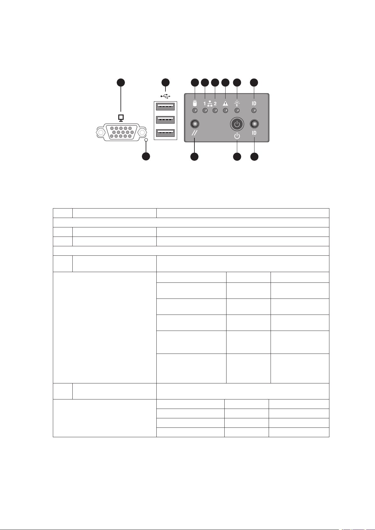
The standard control panel provides a user interface for system management via switches and status
LEDs. The control panel also contains the speaker. Figure 3 shows the location of the buttons and
status LEDs on the standard control panel.
Figure 3. Front Panel Controls and Indicators
Table 4. Front Panel Controls and Indicators
Item Feature Description
Front Panel Connectors
A Video connector Video port, standard VGA compatible, 15-pin connector
B Three USB connectors Three USB 2.0 ports, 4-pin connectors
Front Panel Buttons and LED Indicators
C Hard Drive Activity LED
(Green/Amber)
D,
E
LAN1, LAN2 Status LEDs
(Green)
Indicates hard drive activity and fault status.
LED State Description
Green, On A hard drive is
being initialized.
Green, Blinking A hard drive is
active.
Amber, On Hard drive/slot
failure.
Amber, Slow Blinking
(~1 Hz)
Amber, Fast Blinking
(~2.5 Hz)
Indicates LAN activity status
LED State Description
Off
On Inactive No Access
Blinking Active Access
Idle
A predictive hard
drive/slot failure or
rebuild in process.
Hard drive rebuild
interrupted or
rebuild on empty
slot.
16 17MAXDATA PLATINUM 7200 IR M5Platform Description
Item Feature Description
F System Status/Fault LED
(Green/Amber)
G System Power LED
(Green)
H System ID LED (Blue) Identifies the system via server management or locally.
I NMI button Asserts NMI.
J System Reset button Press to reset the system.
K System Power button Press to turn the system power on or off.
L System ID button Press to turn the System ID LED on or off.
Indicates system status.
LED State Description
Off
Green, On Ready System booted
Green, Blinking Degraded CPU or DIMM
Amber, On Critical Alarm Critical Power
Amber, Blinking
Indicates system power status.
LED State ACPI
Off Power off
On Power on No
Off
Blinking S1 Yes
On S0 Yes
Not ready AC Power Off,
POST error
and ready
disabled
Supply, Blower,
Voltage, or
Temperature
failure
Non-Critical
Alarm
S4/S5 Yes
Redundant Power
Supply or Blower
failure. NonCritical Blower,
Voltage, and
Temperature
failure.
No
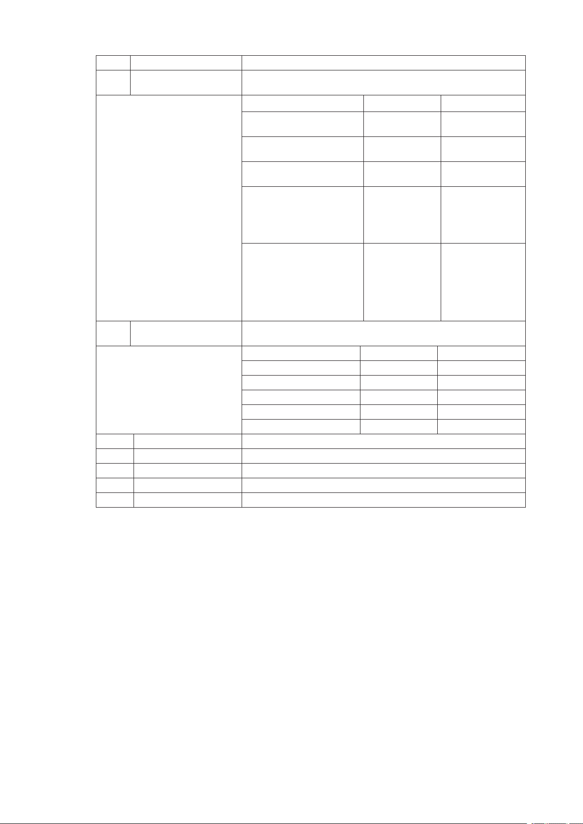
Local Control Panel
A
B
C
D
E
M L K J I GH F
Table 5. Local Control Panel
Item Feature Description
A LCD display Video display
B Scroll up button Press to scroll up on the LCD.
C Scroll down button Press to scroll down on the LCD.
D Back button Press to move to the previous LCD screen.
E Select button Press to enter a command or select an option on the LCD.
F System ID LED (Blue) Helps identify the system via server management.
G System Power LED (Green) Indicates system power status.
H System Power button Toggles system power
I System Status/Fault LED
(Green/Amber)
J,K
LAN1, LAN2 Status LEDs
(Green)
Figure 4. Local Control Panel
Off Power off ACPI: No
Off Power on ACPI: No
Off
Blinking S1 ACPI: Yes
On S0 ACPI: Yes
Indicates system status.
Off
Green, On Ready System booted and ready
Green, Blinking Degraded Processor or DIMM disabled
Amber, On
Amber, Blinking
Indicates LAN activity status.
Off
On Inactive No access
Blinking Active Access
S4 / S5 ACPI: Yes
Not ready AC power off, POST error
Critical
Alarm
Non-Critical
Alarm
Idle
Critical power supply, blower,
voltage, or temperature failure
Redundant power supply or
blower failure.
Non-critical blower, voltage, or
temperature failure.
18 19MAXDATA PLATINUM 7200 IR M5Platform Description

Item Feature Description
L Hard Drive Status LED
(Green/Amber)
M System Reset button Resets the system.
Indicates hard drive activity and fault status.
Green On A hard drive is being
Green Blinking A hard drive is active.
Amber On Hard drive/slot failure.
Amber Slow
Amber Fast Blinking
Blinking
(~1 Hz)
(~2.5 Hz)
initialized.
A predictive hard drive/slot
failure or rebuild in process.
Hard drive rebuild interrupted
or rebuild on empty slot.
Platform Rear
A
C D
1 7
432 5 6
B
E
F
G
H1
JH2L
K
I
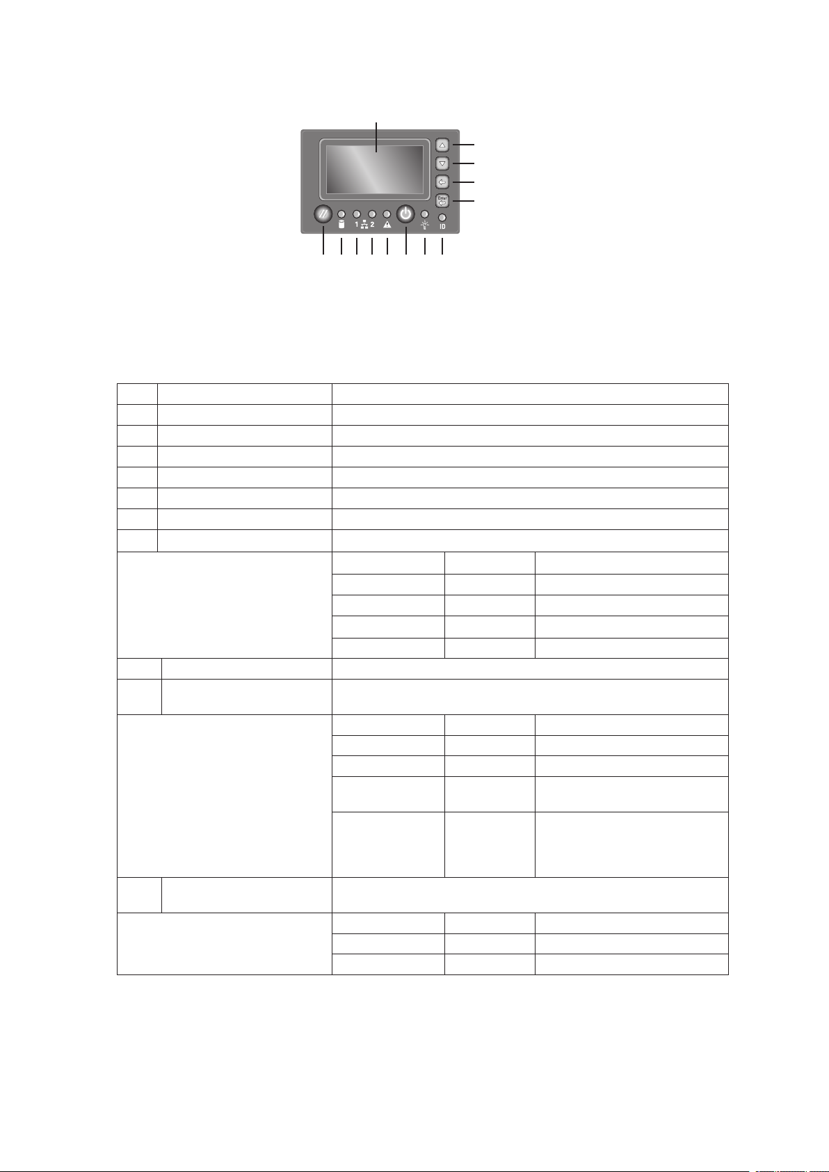
Figure 5 shows the features on the chassis back panel.
Figure 5. Rear Platform Features
Table 6. Rear Platform Features
Item Description
A Serial port connector. Emergency Management Port access is provided through the serial port.
B PCI Slots
Slot 1 PCI-Express x8 (hot-plug)
Slot 2 PCI-X 133 MHz, 64-bit (hot-plug)
Slot 3 PCI-Express x4 (hot-plug)
Slot 4 PCI-Express x4 (hot-plug)
Slot 5 PCI-Express x4 (hot-plug)
Slot 6 PCI-X 100 MHz, 64-bit (not hot-plug)
Slot 7 PCI-X 100 MHz, 64-bit (not hot-plug)
C External SCSI connector. The external SCSI bus supports both LVDS and SE signals through
the external SCSI connector.
D Fibre Channel Module Slot
E Video port, standard VGA compatible, 15-pin connector
F Two USB 2.0 ports
G Two LAN ports, RJ45 connector (LAN1 on top, management features, LAN2 on bottom)
LAN port LEDs:
Status LED
(Green)
Speed LED
(Green/Amber
dual color)
AC input power connectors
H1,
H2
I System ID button
J System ID LED (blue)
K DC jack (not used)
L Server Management RJ-45 connector (GCM) (Advanced Management Module only)
On: ethernet link is detected
Off: no ethernet connection
Blinking: ethernet link is active
Off: 10 Mbps
Green On: 100 Mbps
Amber On: 1000 Mbps
20 21MAXDATA PLATINUM 7200 IR M5Platform Description

Processors
The PLATINUM 7200 IR Server supports from one to four 64-bit Intel® Xeon™ Processor MP with 1 MB
L2 Cache or one to four 64-bit Intel® Xeon™ Processor MP with 8 MB L3 Cache. These processors
are targeted for multiprocessor servers. Several architectural and microarchitectural enhancements
have been added to this processor, including an increased L2 cache size and an integrated L3 cache
(64-bit Intel® Xeon™ Processor MP with 8 MB L3 Cache).
Plug-in Voltage Regulator Module (VRM) Converters
Two types of plug-in voltage regulator module (VRM) converters are used in the system:
• VRM 9.1
• VRM 10.2
Input power to the Main Board is 12 V and 3.3 V Standby (VSB). All other voltages must be generated
on the board set including 3.3 V and 5 V. There are numerous VRDs used to generate the required
voltage levels. Processor core voltage to processors 1 and 2 is generated by embedded VRDs.
Processors 3 and 4 require one plug-in 10.2 VRM each to provide the core voltage. A plug-in VRM
9.1 is required when using more than 2 processors with iL3 cache.
System Memory
The Memory Boards connect to the Main Board through x16 PCI Express connectors. Between one
and four Memory Boards can be installed. Each Memory Board has four DIMM sockets and supports
two DDR2 channels with two DIMMs per channel. The Memory Boards support both single-rank and
double-rank registered DIMMs.
The DIMMs on each Memory Board must be installed in pairs. Each pair is referred to as a bank.
A bank may consist of one rank (a pair of single-sided DIMMs) or two ranks (a pair of double-sided
DIMMs). The BIOS executes a memory test prior to configuring the memory in POST and when a
Memory Board is inserted into the system during a hot plug operation.
A DIMM bank will be disabled if any of the following occur:
• Uncorrectable errors are found during a memory test
• An uncorrectable ECC error occurred during runtime
• The DIMM rank correctable error count passes the error sparing threshold on a Memory Board
where sparing is enabled
• A Memory Board fails
If a DIMM fails the memory test, an LED will light on the Memory Board to identify the location of the
bad DIMM and the DIMM bank will be disabled. The failing DIMM event is logged to the System Event
Log (SEL) and the BIOS disables the memory DIMM and/or the Memory Board. Upon subsequent
reboots, this memory is not initialized unless the BIOS setup option “Retest all system memory” or
“Retest board memory” is selected.

Available Memory Configurations
Four memory configurations are available in the BIOS Setup utility.
• Maximum Performance: Maximum Performance is the default configuration in BIOS setup.
With this configuration, the BIOS first attempts to configure the Memory Boards as fourway interleaved. If four-way interleaving cannot be accomplished, it will attempt to two-way
interleave. It will then use one-way interleaving if any remaining memory cannot be fourway or two-way interleaved. This interleaving process configures the memory for maximum
performance. This configuration cannot be used if you want hot-add or hot-replace memory.
• Maximum Compatibility: Maximum Compatibility provides the most flexibility with DIMMs
and Memory Boards. This option allows memory to be hot-added and hot-replaced. Server
performance will be reduced due to one-way interleaving.
• Memory Mirroring: The Memory Mirroring feature provides redundancy. It uses either two
or four Memory Boards, paired as sets of two. Memory Boards in slots A and B form one set.
Memory Boards in slots C and D form the second set. One board within a set of Memory
Boards duplicates the second board in the set. Each Memory Board in a set must have the
same amount of memory installed.
When a hardware or DIMM error is detected on a primary Memory Board, the second board
becomes the primary board and remains primary until the failing board or DIMM is replaced.
Memory Mirroring uses board-level redundancy, allowing for hot-replacement. The hot-add is
supported by adding two addition mirrored Memory Boards.
The BIOS turns on the mirror LED on each Memory Board when the system is configured for
mirroring.
• Memory RAID: If the server contains four Memory Boards with equal memory capacity, the
system can be configured for Memory RAID. Data is written to three of the Memory Boards
while one is reserved for redundant parity information. This reduces the total overall available
memory by one-fourth. The RAID LED on the Memory Board will indicate that the Memory
Board is in a RAID configuration.
When a DIMM rank or board fails, the system will continue to operate with the remaining
three boards by recreating the data from the failed board. The system loses its redundancy at
this point, and will remain in this non-redundant state until the failing board and/or memory is
replaced.
This configuration allows for hot-replacement of failing Memory Boards and hot-add and hot-
replacement of memory DIMMs.
22 23MAXDATA PLATINUM 7200 IR M5Platform Description

The server BIOS also includes two additional memory reliability, accessibility, and serviceability (RAS)
features:
• Memory Sparing: A rank on each Memory Board can be reserved as a “spare” and can
only be used as a backup for other ranks on the same Memory Board. The memory rank that
is configured as spare is held in reserve and cannot be used by the operating system. Hot
removal cannot be performed when in a Memory Sparing configuration.
When the error rate for a failing rank exceeds an established threshold, the contents of that
rank are copied to the spare rank. At the completion of the copy, the failing rank is disabled
and the spare is used in its place. This is called Memory Sparing. By enabling memory sparing,
the total memory of each Memory Board is reduced by the largest DIMM rank installed on the
Memory Board. This ensures that any failing rank will fit on the spare rank.
When the failing rank switches to the spare, the BIOS will turn on the Memory Board LED to
indicate the bad rank. The failing DIMM rank is then disabled on subsequent system boots.
• Memory Hot Plug: This memory RAS feature provides the ability to hot-replace and hot-add
Memory Boards while the system is running. This feature can be used to perform:
- Memory Hot Replace: While the system is in operation, you can remove a failed Memory
Board, provided it is in a RAID or Mirror configuration, and replace it with a board of the
same memory capacity. The system will test, initialize, and rebuild the data on the Memory
Board and then include this board in the system memory configuration. The activity is
transparent to the operating system,
- Memory Hot Add: You can increase the memory capacity of the system while the
operating system is active. In a RAID configuration, you can remove one Memory Board
at a time to upgrade the memory or replace the Memory Board. In a Mirror configuration
you can add an addition two mirrored Memory Boards. In a Maximum Compatibility
configuration, a new Memory Board can be added to an empty slot. When the initialization
is complete, the operating system is informed of the new memory.
NOTE
Memory Hot Add must be supported by the operating system in order to perform this function. Check
for any operating system restrictions.

Power Subsystem
The power subsystem consists of the following:
• Power supply modules
• Plug-in VRM converters
• The Power Distribution Board
The power subsystem can be configured with two power supply modules installed for 1+1 redundancy
at 220 VAC.
Power Supply Modules
The output rating of the power supply is 1470 W when operated between 170 VAC and 264 VAC. It
is a current-sharing power supply with auto-ranging input. The power supply is approximately 7.75
inches wide by 13.5 inches deep by 1.4 inches high. The power supply modules have universal AC
input with Power Factor Correction (PFC) Distributed Power Supplies (DPS). The AC input receptacle
is an IEC-320 C14.
The power supply has two DC outputs: 12 V and 3.3 VSB. The 12 V main power is distributed
through the server and is converted locally at the point-of-load using either embedded or plug-in VRM
converters. The power supply is capable of power-safe monitoring.
In an N+1 configuration, the 12 VDC outputs have active (forced) current sharing. The two externally
enabled outputs have the following maximum ratings:
• +12 VDC: 121 A
• +3.3 VDCSB: 5 A
Each power supply module requires one power cord to supply AC power to the system. When two
power supply modules and two power cords are installed, the system supports (1+1) power cord
redundancy. This feature allows the system to be powered by two separate AC sources. In the 1+1
configuration, the system continues to operate, without interruption, if one of the AC sources fails.
24 25MAXDATA PLATINUM 7200 IR M5Platform Description
 Loading...