

Marantz PM-KI-PEARL Service Manual
Service
PM-KI-PEARL
PM-13S2
PM-KI-PEARL /
PM-13S2 /
FN/K1G
N1B/U1B
Manual
SECTION PAGE
1. TECHNICAL SPECIFICATIONS............................................................................................1
2. CAUTION ...............................................................................................................................1
3. ALIGNMENTS ........................................................................................................................2
4. SERVICE MODE ....................................................................................................................4
5. PROTECTION MODE ............................................................................................................6
6. MAIN MICROPROCESSOR (QU01) UPDATE PROCEDURE ..............................................8
7. WIRING DIAGRAM ..............................................................................................................23
8. BLOCK DIAGRAM ...............................................................................................................25
9. SCHEMATIC DIAGRAM ......................................................................................................27
10. PARTS LOCATION ..............................................................................................................39
11. EXPLODED VIEW AND PARTS LIST ..................................................................................65
12. MICROPROCESSOR AND IC DATA ...................................................................................71
13. ELECTRICAL PARTS LIST ..................................................................................................77
14. AFTER REPLACEMENT OF U-PRO OR FLASH ROM ......................................................94
Integrated Amplier
TABLE OF CONTENTS
X0477V02DM/DG0910
Please use this service manual with referring to the user guide (D.F.U.) without fail.
修理の際は、必ず取扱説明書を準備し操作方法を確認の上作業を行ってください。
PM-KI-PEARL
PM-13S2
Copyright 2009 D&M Holdings Inc. All rights reserved.
WARNING: Violators will be prosecuted to the maximum extent possible.
Ver. 2
Please refer to the
MODIFICATION NOTICE.
Part no. 90M28AJ855020
First Issue 2009.10
MARANTZ DESIGN AND SERVICE
USA
MARANTZ AMERICA, INC
100 CORPORATE DRIVE
MAHWAH, NEW JERSEY 07430
USA
EUROPE / TRADING
D&M EUROPE B. V.
P. O. BOX 8744, BUILDING SILVERPOINT
BEEMDSTRAAT 11, 5653 MA EINDHOVEN
THE NETHERLANDS
PHONE : +31 - 40 - 2507844
FAX : +31 - 40 - 2507860
KOREA
D&M SALES AND MARKETING KOREA LTD.
CHUNG JIN B/D., #1001,
53-5, WONHYORO 3 GA, YONGSAN-GU,
SEOUL, 140-719, KOREA
PHONE : +82 - 2 - 323 - 2155
FAX : +82 - 2 - 323 - 2154
CANADA
D&M Canada Inc.
5-505 APPLE CREEK BLVD.
MARKHAM, ONTARIO L3R 5B1
CANADA
PHONE : 905 - 415 - 9292
FAX : 905 - 475 - 4159
JAPAN
D&M BUILDING, 2-1 NISSHIN-CHO,
KAWASAKI-KU, KAWASAKI-SHI,
KANAGAWA, 210-8569 JAPAN
D&M Holdings Inc.
CHINA
D&M SALES AND MARKETING SHANGHAI LTD.
ROOM.808 SHANGHAI AIRPORT CITY TERMINAL
NO.1600 NANJING (WEST) ROAD, SHANGHAI,
CHINA. 200040
TEL : 021 - 6248 - 5151
FAX : 021 - 6248 - 4434
Using superior design and selected high grade components,
Only original
MARANTZ
parts can insure that your
MARANTZ
MARANTZ
company has created the ultimate in stereo sound.
product will continue to perform to the specications for
which it is famous.
Parts for your
MARANTZ
ORDERING PARTS :
equipment are generally available to our National Marantz Subsidiary or Agent.
Parts can be ordered either by mail or by Fax.. In both cases, the correct part number has to be specied.
The following information must be supplied to eliminate delays in processing your order :
1. Complete address
2. Complete part numbers and quantities required
3. Description of parts
4. Model number for which part is required
5. Way of shipment
6. Signature : any order form or Fax. must be signed, otherwise such part order will be considered as null and void.
NOTE ON SAFETY :
Symbol Fire or electrical shock hazard. Only original parts should be used to replaced any part marked with symbol .
Any other component substitution (other than original type), may increase risk of re or electrical shock hazard.
安全上の注意:
がついている部品は、安全上重要な部品です。必ず指定されている部品番号のものを使用して下さい。
SHOCK, FIRE HAZARD SERVICE TEST :
CAUTION : After servicing this appliance and prior to returning to customer, measure the resistance between either primary
AC cord connector pins (with unit NOT connected to AC mains and its Power switch ON), and the face or Front Panel of
product and controls and chassis bottom.
Any resistance measurement less than 1 Megohms should cause unit to be repaired or corrected before AC power is applied,
and veried before it is return to the user/customer.
Ref. UL Standard No. 60065.
In case of difculties, do not hesitate to contact the Technical
Department at above mentioned address.
080702MZ
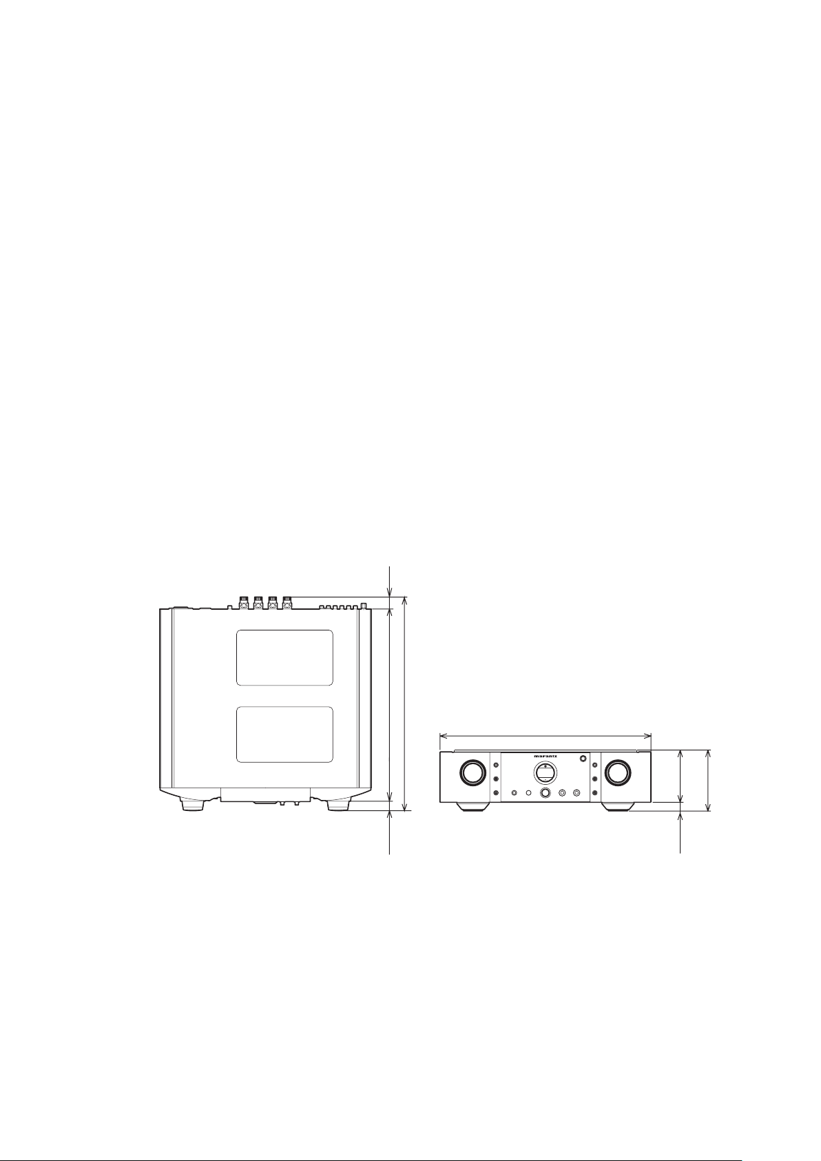
1. TECHNICAL SPECIFICATIONS
127 (5)
109
(4-5/16)
440 (17-3/8)
444 (17-1/2)
400 (15-3/4)
19
(3/4)
25
(1
)
18
(3/4)
Power output (20 Hz – 20 kHz simultaneous drive of both
channels) .................(8Ω load) 90 W x 2 [ N1B / U1B / FN ]
............................................................. 80 W x 2 [ K1G ]
...........................(4Ω load) 140 W x 2 [ N1B / U1B / FN ]
............................................................ 130 W x 2 [ K1G ]
Headphone rated output (When speaker rated output set
to 8 Ω load) .................................... 120mW x 2 (32 Ω load)
Total harmonic distortion (20Hz – 20kHz simultaneous
drive of both channels, 8 Ω load) ............................. 0.05 %
Output band width (8Ω load, 0.05%) ............5 Hz ~ 40 kHz
Frequency response (CD, 1W, 8Ω load)
..................................................... 5 Hz ~ 100 kHz ±3 dB
Dumping factor (8Ω load, 20Hz – 20kHz) ..................... 100
Input sensitivity/Input impedance
PHONO (MC) ............................................ 270 µV/100 Ω
PHONO (MM) .............................................2.7 mV/47 kΩ
CD/LINE ....................................................240 mV/20 kΩ
P.DIRECT IN .................................................1.7 V/20 kΩ
Output voltage/Output impedance
PRE OUT ..................................................... 1.7 V/220 Ω
Maximum allowed PHONO input (1kHz)
MC .........................................................................15 mV
MM ...................................................................... 150 mV
RIAA deviation (20Hz ~ 20kHz) .......................... ±0.5 dB
S/N (IHF-A, 1W, 8Ω load)
PHONO MC (0.5mV input) ..................................... 75 dB
PHONO MM (5mV input) .......................................86 dB
CD/LINE (500mV input) .........................................89 dB
Tone control
Bass (50Hz) .........................................................±10 dB
Treble (20kHz) .....................................................±10 dB
Power requirement
(U.S.A.) ..................................................AC 120 V 60 Hz
(Europe) ............................................AC 230 V 50/60 Hz
(Japan) ..............................................AC 100 V 50/60 Hz
(China) ...................................................AC 220 V 50 Hz
Power consumption
(EN60065 7th Ed.) ................................................220 W
(UL60065) ............................................................. 220 W
(J60065) ................................................................ 220 W
2. CAUTION
The layout of this amplier is well concerned for sound
quality.
1. When screws and washers are removed, those parts
must be set to the same places.
2. When wires are removed, the wires must be installed in
the same roots, same places.
3. Do not hold the side panel (007D) to move the unit when
the unit is disassembled.
2. 注意
当機は音質を考慮したレイアウトになっています。
1. ネジやワッシャ類を取り外した場合、元の位置に取り付けて
ください。
2. ワイヤ類を取り外した場合の配線ルートは、元のルート通り
に戻してください。
3. 当 機を分 解した状 態で移 動するときは、サイドパネル
(007D)を持たないでください。
1
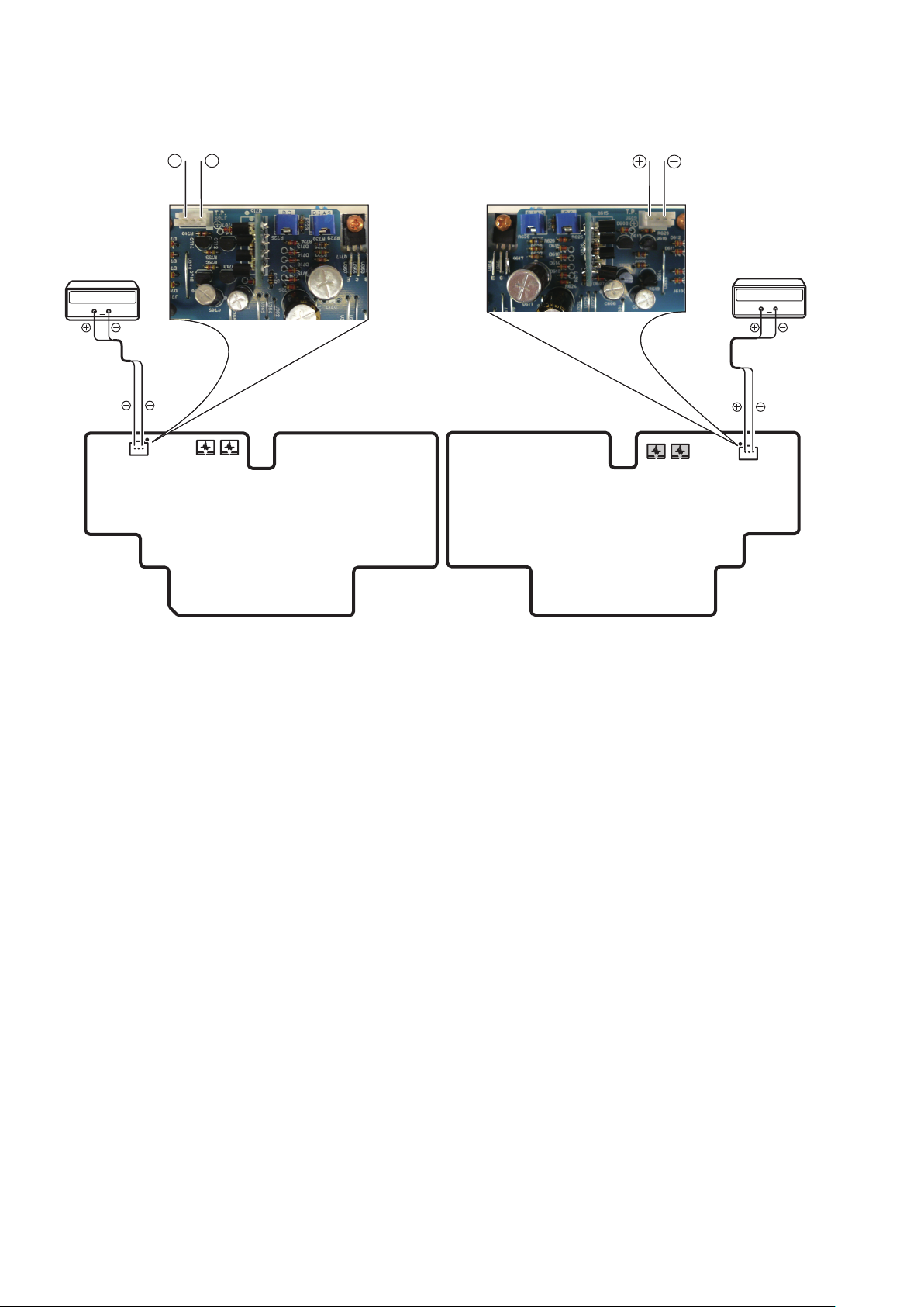
2
P701 P601
R729
J709
R629
R625
J609
R725
Digital Voltmeter
R ch
V
Digital Voltmeter
L ch
V
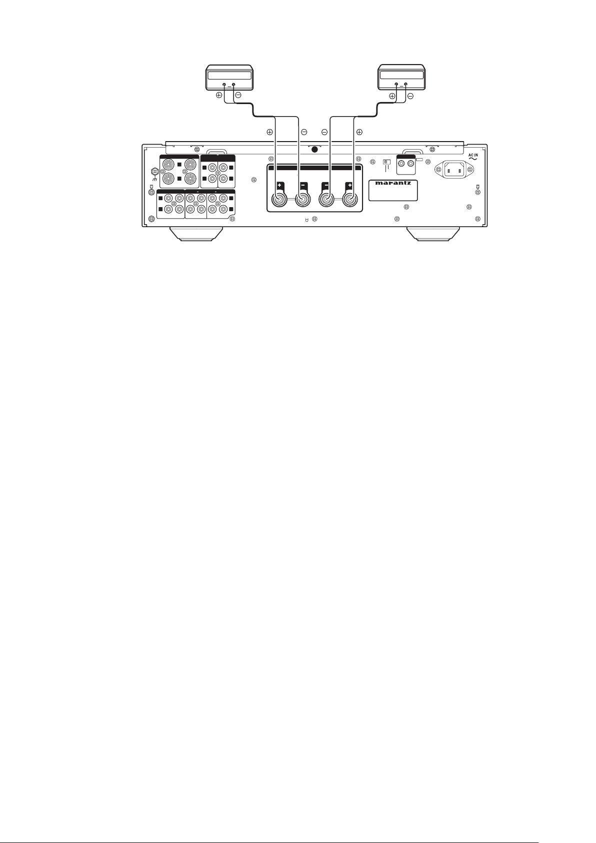
3. ALIGNMENTS
Idling Current Adjustment
アイドリング電流調整
1. Digital voltage is connected with Lch/Rch of the speaker
terminal of a rear panel respectively. "+" of Connect
Digital Voltage is connected to the "+" of the terminal.
"-" of Connect Digital Voltage is connected to the "-" of
the terminal.
2. "+" of Connect Digital Voltage is connected to the No.1
pin and connected "-" to No.3 pin of J609 (J709).
3. Function is CD. Volume is set as -∞. Do not connect
anything with the input terminal.
4. Before turning on the power, R625 and R729 have been
center then R629 and R729 have been counter clockwise
turned with the adjustment driver.
1. リアパネルのSPEAKER の LchとRch の端子にデジタル
ボルトメーターを接続します。デジタルボルトメーターは、
Lch および Rch の "+"を"+" に、 "-"を"-" に接続します。
P601/P701
2.
基板の
J609/J709
にデジタルボルトメーターを
接続します。デジタルボルトメーターは
ピンを"+"、 3 番ピンを"-" に接続します。
3. PM-KI-PEARL / PM-13S2 のファンクションは CD にして、
ボリュームは-∞に、入力端子には何も接続しないでくださ
い。
4. 電源を投入する前に、半固定抵抗
に合わせ、
R629とR729
を、調整ドライバーで反時計方向
R625とR725
に回しきってください。
J609/J709
はセンター
の 1 番
3
DC Offset Voltage Adjustment
PHONO
GND
STEREO
BI.AMP
HC LHC R
SPEAKER SYSTEMS
IN OUT
F.C.B.S.
PRE OUT
RECORDER
21LINE 21
OUTOUTIN IN
PHONOCD
L
R
L
R
L
R
L
R
L
R
SPEAKER IMPEDANCE : 4-8 OHMS
P.DIRECT
IN
ININ
ININ
Digital Voltmeter
V
Digital Voltmeter
V
5. First, adjust the DC offset voltage with the variable resistor
R625 and R725 on the PCB (P601/P701).
6. Turn on the power. Turn on the button of SPEAKERS.
7. After turning on the speaker relay, with seeing the digital
voltage meter connected with the Lch terminal turn the
variable resister slowly to adjust the DC offset adjustment
with R625. Next, with seeing the digital voltage meter
connected with the Rch terminal turn the variable resister
slowly to adjust the DC offset adjustment with R725.
• Turn R625(R725) clockwise to decrease the DC offset
voltage. And counter clockwise to increase.
• The voltage changes delaying, and turn slowly.
• The adjustment value of DC offset voltage is
0mV±10mV each.
DC オフセット電圧調整
5. 最初に、
P601/P701
基板上の半固定抵抗
でDCオフセットを調整します。
6. 電源を投入し、SPEAKERS のボタンをONしてください。
7. スピーカーリレーがオンした後、SPEAKER SESTEM 端子
の Lch に接続したデジタルボルトメーターの電圧値を監視
しながら、
R625
をゆっくりとまわしてください。次にRch に
接続したデジタルボルトメーターの電圧値を監視しながら、
R725
をゆっくりとまわしてください。
R625 とR725
•
を時計方向に回すとオフセット電圧が減少
します、反対に回すと増加します。
• 電圧は遅れて変化しますので、ゆっくり回してください。
• オフセット電圧の調整値はそれぞれ0mV±10mV以内に
します。
R625とR725
Idling Current Adjustment
8. Next, Adjust the Idling Current.
9. Turn on the power. After 2 minutes, with seeing the digital
10. After 7minutes, repeat the same procedure as 9.
Adjustment is completed.
11. Remove connection cable, attach the top cover.
voltage meter turn the variable resister clockwise slowly
to adjust the idling current. Idling adjustment with R629.
R729 is similarly adjusted.
• Turn R629 (R725) clockwise to increase the idling
current.
• The adjustment value of idling current is 5.0mV (25mA)
±0.5mV (2.5mA) each.
• The adjustment value of idling current is 11.0mV
(55mA) ± 0.5mV (2.5mA) each.
アイドリング電流調整
8. 次にアイドリング電流を調整します。
9. 電源を投入してから2 分経過後、
P601
したデジタルボルトメーターの電圧値を監視しながら半固
R629
定抵抗
P701
に
電圧値を監視しながら半固定抵抗
をゆっくりと時計方向に回してください。次
J709
基板の
に接続したデジタルボルトメーターの
R729
方向に回してください。
R625とR725
•
を時計方向に回すとアイドリング電流が増
加します。
• アイドリング電 流の調 整 値はそれぞれ5.0mV±0.5mV
以内にします。
10. さらに7分経過後、上記 9 の手順でもう一度調整します。
• アイドリング電流の調 整 値はそれぞれ11.0mV±0.5mV
以内にします。
以上で調整は完了です。
11. デジタルボルトメーターの接続を外し、トップカバーを取り付
けます。
J609
基板の
をゆっくりと時計
に接続
4
4. SERVICE MODE
DISPLAY button DISPLAY ATT button
POWER ON/OFF button
PHONO
GND
STEREO
BI.AMP
HC LHC R
SPEAKER SYSTEMS
IN OUT
F.C.B.S.
PRE OUT
RECORDER
21LINE21
OUTOUTIN IN
PHONO CD
L
R
L
R
L
R
L
RLR
SPEAKER IMPEDANCE : 4-8 OHMS
P.DIRECT
IN
ININ
ININ
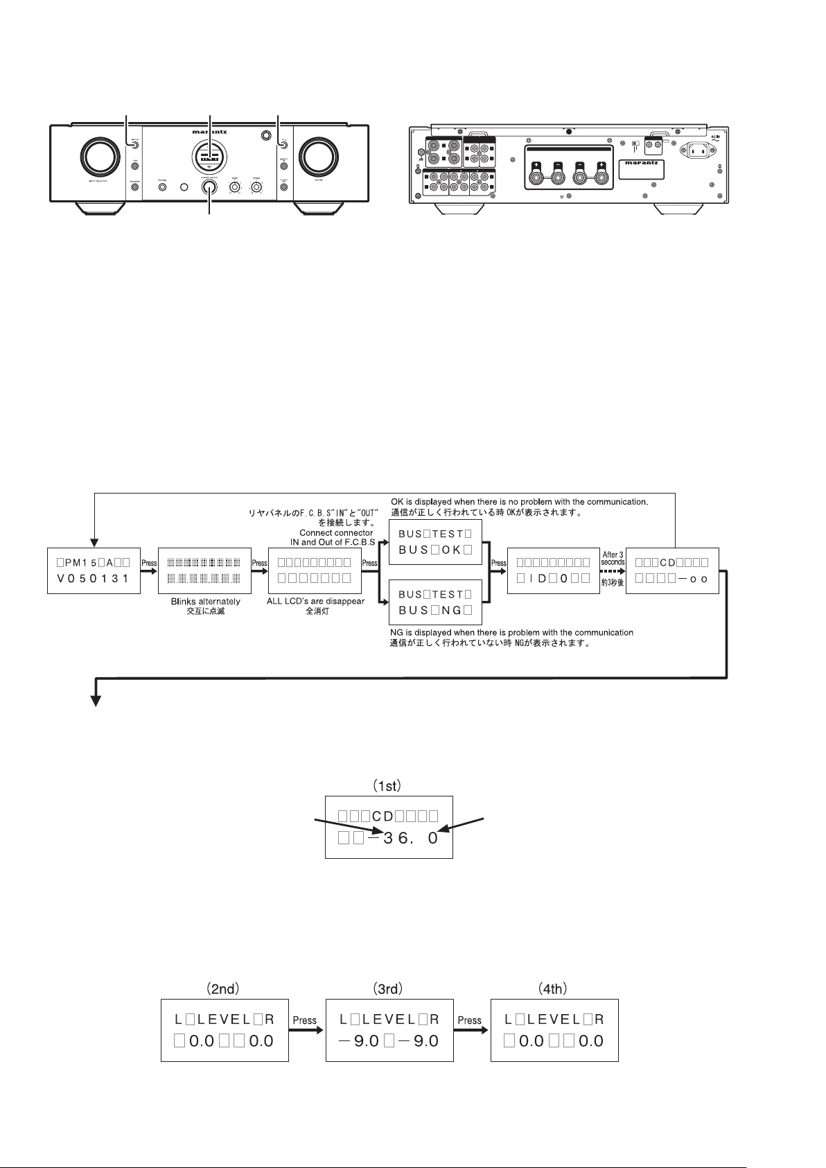
1. To enter the Service Mode, press the POWER ON/OFF
button with pressing the DISPLAY and AT T buttons to
turn on the unit. (Or when the remote code "166363" is
received while power is ON.)
When into the Service Mode, the memory is cleared and
the unit is initialized.
2. The Model name and Version number are displayed on
the Front LCD.
Whenever press the DISPLAY button, the display
changes as follows.
Turn off power to quit service mode.
1. 本 体 の
POWER ON/OFF
DISPLAY
ボタンと
ボタンを押します。
ATT
ボタン を 押し なが ら
(または、電源ON 中にリモコンコード"166363" を受信しま
す。)これでサービスモードに入ります。
注意:サービスモードに入ると、全ての設定がクリアされ出
荷状態になります。
2. 始めにモデル名、バージョンが表示されます。
DISPLAY
POWER ON/OFF
ボタンを押すたびに下記の表示となります。
ボタンを押し、電源を切るとサービスモー
ドが解除されます。
THE TRIM CHECK MODE
1. Press TONE button. (1 st)
Volume Level is displayed .
This is an example
After, whenever press the TONE button, TRIM adjustment
function works and output level changes according to the
display.
Whenever press the TONE button, the display changes
as follows and output level changes according to the
display.
TRIM check mode is completed.
TRIM チェックモード
TONE
1.
ディスプレイに音量が表示されます。
以降、
TRIMチェックモードは終了です。
ボタンを押します。(1 回目)
数値は(例)です
TONE
ボタンを押すごとにトリム調整機能が働き表示
に従い出力レベルが変化します。
TONE
ボタンを押すごとに下記のように表示が変わり、表
示に従い出力レベルが変わります。
5
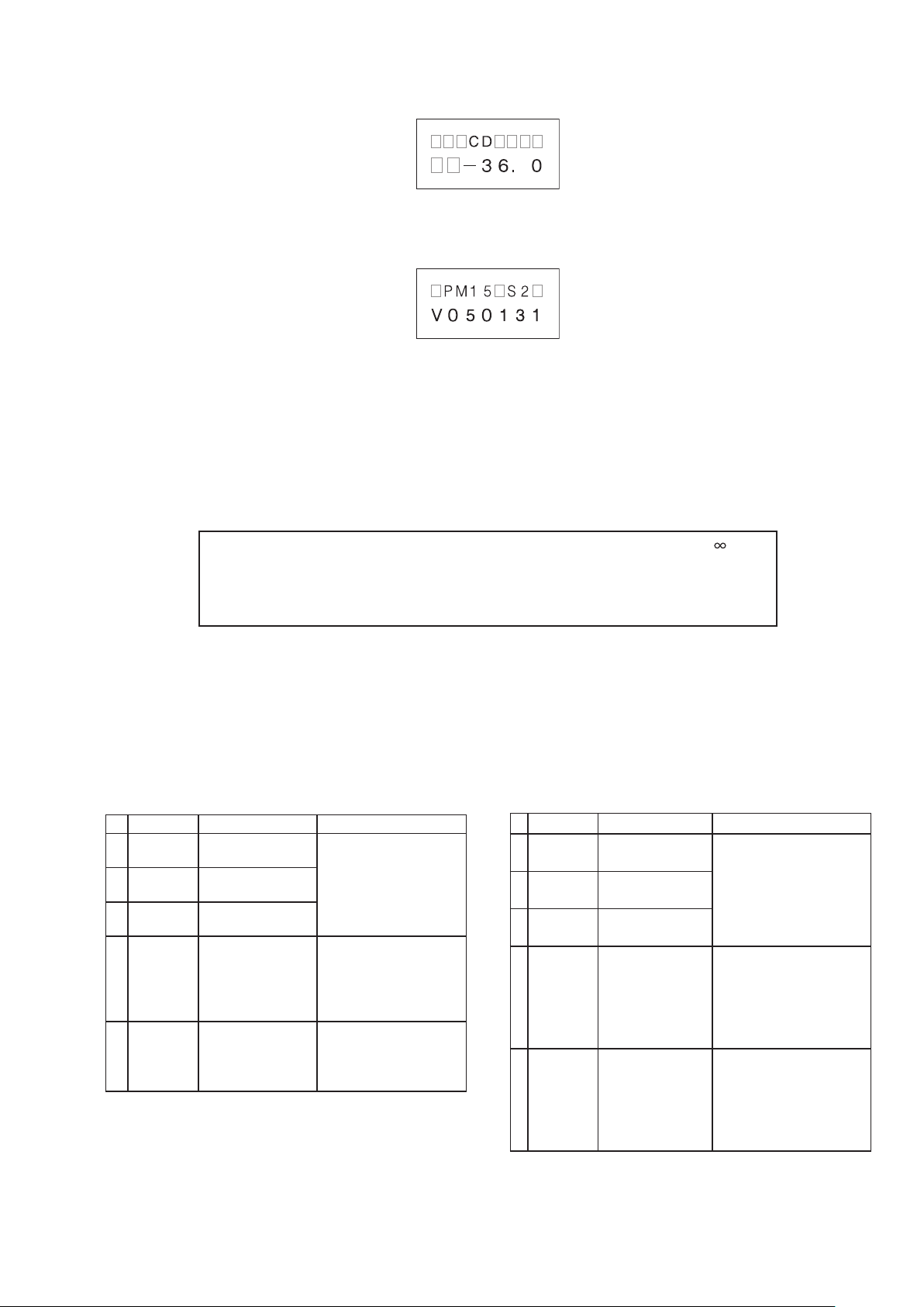
2. Press DISPLAY button, the display will be the following.
DISPLAY
2.
ボタンを押します。下記の表示になります。
3. Press DISPLAY button, the display will be the following.
4. Turn off power to quit service mode.
Service mode can be ended if turn off power from every
procedure.
The memory is cleared and the unit is initialized.
Initial settings
ID No.: 0 INPUT SELECTOR: CD VOLUME: -
SIDE ILLUMINATION: ON DISPLAY: ON ATT: OFF
LEVEL TRIM: 0.0 (L/R) TONE: OFF SPEAKER : OFF
ATT: -20dB P.DIRECT: OFF PHONO MC:OFF
Be sure to set up manually.
MODE SW on Rear panel: STEREO
POWER ON/OFF SW: OFF
DISPLAY
3.
POWER ON/OFF
4.
ボタンを押します。下記の表示になります。
ボタンを押し、電源を切ります。サービ
スモードが解除されます。
サービスモードはどの手順からも電源を切ると終了すること
ができます。
本体の設定は全て下記の出荷状態になります。
出荷状態内容
下記は、手動で設定
MODE SW: STEREO(必ず設定)
POWER ON/OFF SW: OFF
ERROR MESSAGES
Error Contents Measure
1 ERROR 02
2 ERROR 03
3 ERROR 04
4 ERROR 11
5 ERROR 12
The units of ID No.2
overlaps.
The unit of ID No.3
overlaps.
The unit of ID No.4
overlaps.
The unit of ID No.2
to No.4 cannot
communicate with
the unit of ID No.1.
The unit of ID No.1
cannot communicate
with the unit of ID
No.2 to No.4.
ID number is changed into
the ID No. not overlapping.
• If the unit ID number 1 is
not turn on, turn on the
unit ID No.1.
• Check the remote cable
is connected correctly.
• ID No. is changed into ID
No. not overlapping.
• Check the remote cable
is connected correctly.
エラーメッセージ
表 示 内 容 対 策
1 ERROR 02
2 ERROR 03
3 ERROR 04
4 ERROR 11
5 ERROR 12
ID 番 号 2 のアンプが
重複しています。
ID 番 号 3 のアンプが
重複しています。
ID 番 号 4 のアンプが
重複しています。
ID 番 号 2 〜 4 のアン
プがID 番 号 1 のアン
プと通信できません。
ID 番 号 1 のアンプが
ID 番 号 2 〜 4 のアン
プと通信できません。
ID 番号が重複しないようにID
番号を設定してください。
• ID 番 号 1 のアンプに電 源が
入っていない場 合は電 源を
入れてください。
• リモートケーブルが正しく接
続されているか確認してくだ
さい。
• ID 番 号 1 のアンプが重 複し
ている場合はID 番号を正し
く設定してください。
• リモートケーブルが正しく接
続されているか確認してくだ
さい。

6
5. PROTECTION MODE
5. PROTECTION 動作について
Explanation of microprocessor (QU01) [PROT-1 (pin54) and
PROT-2 (pin53)].
[A] The PROT-1(pin54) is the port to detect the following
abnormalities of the Power AMP
1. Detection of an abnormality in the DC offset voltage from
the Speaker Output terminal.
If the voltage from the Speaker Output terminal exceeds
approximately ±1.2V (DC), Q954 or Q955 will turn on
and the signal from the PROT-1 terminal will change to
L from H.
2. Detection of an abnormal current from the power
transistors (Q622, Q623, Q722, Q723).
If an electric current of over 10A ows in Q622 or Q623,
Q624, Q625 and Q957 turn on, and the signal from the
PORT-1 terminal will change to L from H.
If an electric current of over 10A ows in Q722 or Q723,
Q724, Q725 and Q957 turn on, and the signal from the
PORT-1 terminal will change to L from H.
3. Detection of an abnormal temperature of the Heat
Sink.
If the temperature of the Heat Sink exceeds approximately
+110 degrees C, the posistor (R672 and R772) will turn
on Q956 and the signal from the PROT-1 terminal will
change to L from H.
マイコン(QU01)のPROT-1 (pin54) とPROT-2 (pin53)の説明。
[A] PROT-1(pin54)は、パワーアンプの下記の異常動作を検
出するポート
1. スピーカー出力端子のDC オフセット電圧の異常電圧を検
出。
スピーカー出力端子が約±1.2V (DC) を超えるとQ954 も
しくはQ955が ONして、PROT-1 端子が "H→ L" になる。
2. パワートランジスタ (Q622, Q623, Q722, Q723) の異常電
流を検出。
Q622もしくはQ623 に約 10A を超える電 流が流れると
Q624, Q625, Q957が ONして、PROT-1 端子が "H → L"
になる。
Q722もしくはQ723 に約 10A を超える電 流が流れると
Q724, Q725, Q957が ONして、PROT-1 端子が "H → L"
になる。
3. ヒートシンクの異常温度を検出。
ヒートシンクの温 度が約 110 ℃ を超えると、ポジスター
(R672, R772)によってQ956が ONして、PROT-1 端子が
"H → L" になる。
1.〜3. のいずれかの異常検出でPROT-1端子が "H→ L" にな
ると保護回路が動作してSPK_OUT (pin40) を "H → L" にし
て、即座にスピーカーリレー L901をOFFにします。
If any of the above three abnormalities is detected, the
signal from the PROT-1 terminal will change to L from H,
and the protection circuit will be activated, the signal from
the SPK_OUT (pin40) changing to L from H and the speaker
relays L901 immediately turned off.
What this protection operation results in after this depends
on how long the signal from the PROT-1 has to remain L.
• If the PROT-1 (pin54) recovers to “H” within as short a
period of time as one second or less.
The message “PROTECT” flashes on the display,
thereby indicates that the protection circuit has come into
operation and automatically turns down the volume.
The protection circuit is deactivated after approximately 8
seconds, so that readjusting the volume will allow normal
use of the unit again. This protection operation is intended
for the situation wherein the user has misused the unit
temporarily and automatically resets the unit while the
amp circuit is functioning properly.
• If the PROT-1 (pin54) remains L for more than one
second.
The amp will be powered off by the POW-1 (pin25)
changing to L from H and Power relay L852 turned off.
Then, the OPERATION indicator flickers, th ereby
indicating that an error has occurred. This protection
operation is intended for a failure in the amp circuit and
immediately turns the power off to avoid the risk of any
damage. Depending on how the user is handling the unit,
this operation may be performed no matter if the amp is
functioning properly.
このPROTECTION 動 作はPROT-1 端 子が "L" になっている
時間によって、その後の動作が異なります。
• PROT-1 (pin54) が 1 秒以内の短時間の間に "H" に復帰
した場合。
デ ィス プ レ イ 部 に "PROTECT" の 文 字 が 点 滅 し、
PROTECTION 動 作になったことを知らせ、自動 的にボ
リュームを下げます。
約 8 秒後に保護回路が解除しますのでボリュームを再調整
すればそのまま使用することができます。
これは、ユーザーが一時的に使用法を誤った場合を想定し
たPROTECTION 動作で、アンプ回路は故障していない場
合に自動復帰する動作です。
• PROT-1 (pin54)が 1 秒以上 "L" になっている場合。
POW-1 (pin25) を "H → L" にして、電源リレー L852 を
OFFし、アンプの電源をシャットダウンします。
このときOPERATEインジケーターが点滅(1 秒間に約2
回)し、異常が起きたことを表示します。
これは、アンプ回路の故障を想定した PROTECTION 動作
で、危険回避のため即座に電源を切る動作です。
ユーザーの使用状況によっては、アンプが故障していなくて
もこの状態になる可能性もあります。
アンプが故障しているかどうかを確認するには、一旦電源
SWを切り1 分ほど待ってから電源 SWを再投入します。
この操作でPROTECTION 動作が解除します。
電源SW を再投入してもPROT-1 (pin54)が "L" の異常状
態の場合は、約2秒後に再びシャットダウンしてOPERATE
インジケーターが点滅します。
電源を再投入してもPROTECTION 動作が解除されない
場合は、アンプ回路が故障していると考えられます。

7
To check if the amp is in order, switch off the unit and switch
it on again one minute later. This action will deactivate
the protection operation. If the PROT-1 (pin54) remains
“L”, which constitutes an abnormality, the unit shuts down
approximately 2 seconds later and the OPERATION indicator
starts ickering.
If the protection operation will not be deactivated after the
power is turned on again, the amp circuit may be broken.
[B] The PROT-2 (pin53) is the port to detect
abnormalities of the power supply circuit
1. Detection of an abnormality in the power amp power
supply circuit.
This port monitors the midpoint voltage of the power amp
power supply between +50V and -50V. If the voltage at
the connection point of R829 and R830 exceeds DC
±1.2V, Q823 or Q824 will turn on to change the signal
from the PROT-2 (pin53) to L from H.
2. Detection of an abnormality in the preamp power supply
circuit.
This port monitors the midpoint voltage between +30V
and -30V. If the voltage at the connection point of R823
and R824 exceeds DC ±1.2V, Q821 or Q822 will turn on to
change the signal from the PROT-2 (pin53) to L from H
3. Detection of an abnormality in the function relay power
supply circuit.
If the +24V of the relay power supply receives an electric
current of over 120mA, Q831 and Q834 will turn on to
change the signal from the PORT-2 (pin53) to L from
H.
4. The Fuse (F851) inside blows, the signal from the PROT-2
(pin53) terminal will be changed to L from H.
[B] PROT-2 (pin53)は、電源回路の異常を検出するポート
1. パワーアンプ用電源回路の異常を検出。
パワーアンプ用電源の +50V と-50V の中点電圧を監視し、
R829とR830 の接続点の電圧が約 ±1.2V (DC) を超え
ると、Q823もしくはQ824 が ONしてPROT-2 (pin53) が
"H → L" になる。
2. プリアンプ用電源回路の異常を検出。
プリアンプ用電源の +30V と -30V の中点電圧を監視し、
R823とR824 の接続点の電圧が約 ±1.2V (DC) を超え
ると、Q821もしくはQ822 が ONしてPROT-2 (pin53) が
"H → L" になる。
3. ファンクションリレー用電源回路の異常を検出。
リレー用電源の+24V に約 120mA を超える電流が流れる
と、Q831, Q834が ONしてPROT-2(pin53)が "H→ L" に
なる。
4. F851 FUSEが切れている場合、Q835が ONし、PROT-2
(pin53) が "H→ L" になる。
1. 〜 4. のいずれかの異 常を検 出すると、POW-1 (pin25) を
"H→L" にして、電源リレー L852 をOFFしシャットダウンします。
このときOPERATEインジケーターが点滅(1秒間に約8回)し、
異常が起きたことを表示します。
これは、アンプ回 路もしくは電 源 回 路の故 障を想 定した
PROTECTION 動作で、危険回避のため即座に電源を切る動
作です。
OPERATEインジケーターが1 秒間に約8 回の速い点滅状態
になると、電源が再投入できないようになります。
これは、電源を再投入することによる危険を回避するためメモ
リーに書き込まれるためです。
電源を投入できるようにするためには、メモリークリアの処理を
行ってください。
If any of the above four abnormalities is detected, the signal
from the POW-1 (pin25) changing to L from H, the power
relay L852 will be turned off and the unit will be shut down.
Then, the OPERATE indicator ickers and indicates that an
abnormality has occurred.
When the OPERATE LED enters the state of blinking eight
times a second, it doesn't return to the normally state.
Because, when the power supply is turned on again, it is
dangerous.
Return to normally operation.
1. Turn off POWER ON/OFF button.
2. One minute after, POWER ON/OFF buttom is turned on
while pushing at the same time as DISPLAY button with
ATT button.
3. The model name and the version are displayed on the
display.
4. Then, turn off POWER ON/OFF buttom. Next, it starts
with the factory shipped when turning on power.
メモリークリアの手順
1. まず、電源をOFF にしてください。
2. 1 分ほど待ってから、本体の
を押しながら
す。これでサービスモードに入ります。
3. ディスプレーにモデル名とバージョンが表示されます。
POWER ON/OFF SW
4.
リアされます。この操作で電源が投入できるようになります
が、この操作をすると全ての設定がクリアされ出荷状態に戻
りますのでご注意ください。
POWER ON/OFF SW
DISPLAY
を押して電源を切ると、メモリーがク
ボタンと
を押し電源を投入しま
ATT
ボタン
8
6. MAIN MICROPROCESSOR (QU01) UPDATE
2*101
)0&
56'4'1
$+#/2
*%.*%4
52'#-'45;56'/5
+0 176
(%$5
24'176
4'%14&'4
.+0'
176176+0 +0
2*101 %&
.
4
.
4
.
4
.
4
.
4
52'#-'4+/2'�%'1*/5
2&+4'%6
+0
+0+0
+0+0
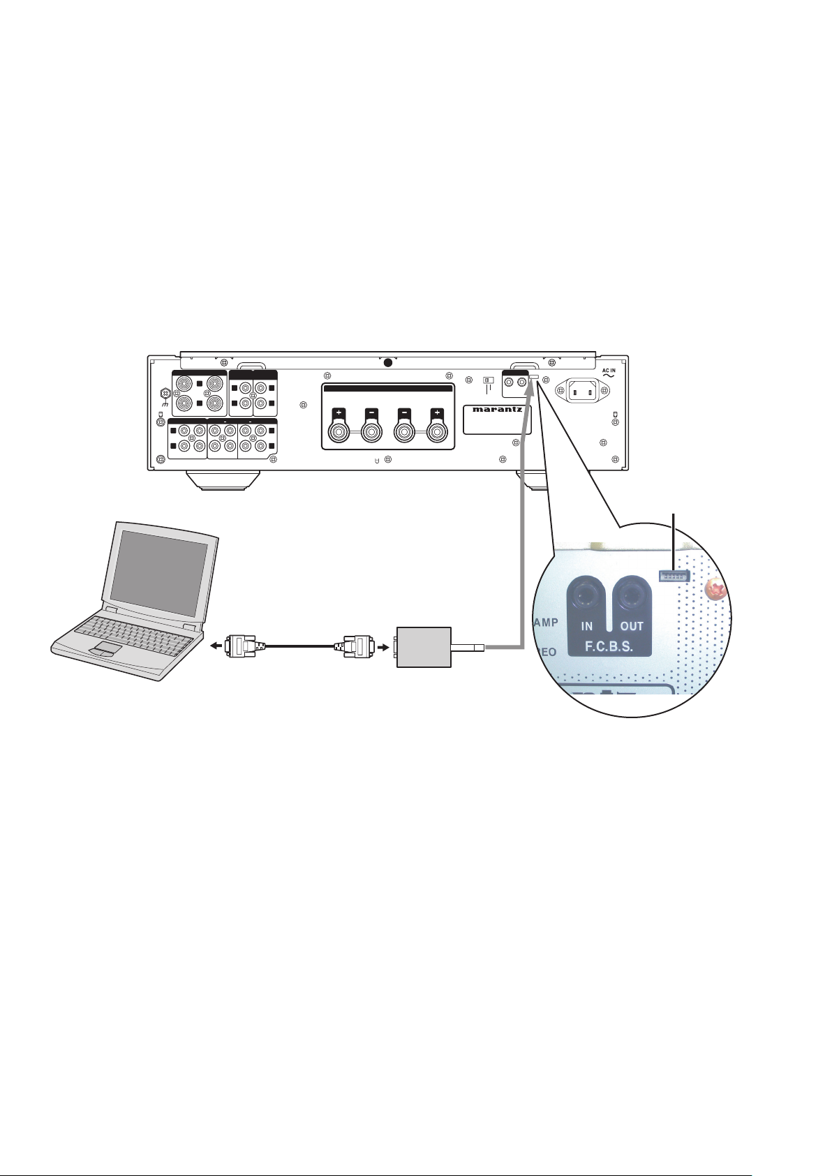
RS232C Dsub-9 pin cable
(female to female/Straight cable)
DATA UPDATE KIT
(Parts No. 90M-PM11S1JIG)
PC (Windows 2000, XP )
with RS-232C port
INSERT POINT
Contact is the bottom
PROCEDURE
6. MAIN MICROPROCESSOR (QU01)
アップデート方法
Necessary Equipment
• Windows PC (Windows2000 or WindowsXP) with
COM port
• RS232C cable straight t ype (9pi n f emale - 9Pin
female)
• Update Disc (90M-PM15S2CDR)
• DATA UPDATE KIT (part no.: 90M-PM11S1JIG)
6.1. Connection
必要機器
• Windows PC (OS:Windows2000 または WindowsXP)
で COM portのあるもの
• RS232Cストレートケーブル (9pinメス- 9pinメス)
• マイコンアップデートディスク (90M-PM15S2CDR)
• マイコンアップデートキット
( 部品番号 : 90M-PM11S1JIG)
6.1. 接続図
9
6.2. Installs of The software
(Flash Development Toolkit 3.0)
6.2. 書き込みソフトウェアのインストール
(Flash Development Toolkit 3.0)
The explanation drawing
• The explanation drawings are using PM-11S1 in this
section. Please replace with PM-KI-PEARL / PM-13S2
the portion currently mentioned as PM-11S1, and operate
it.
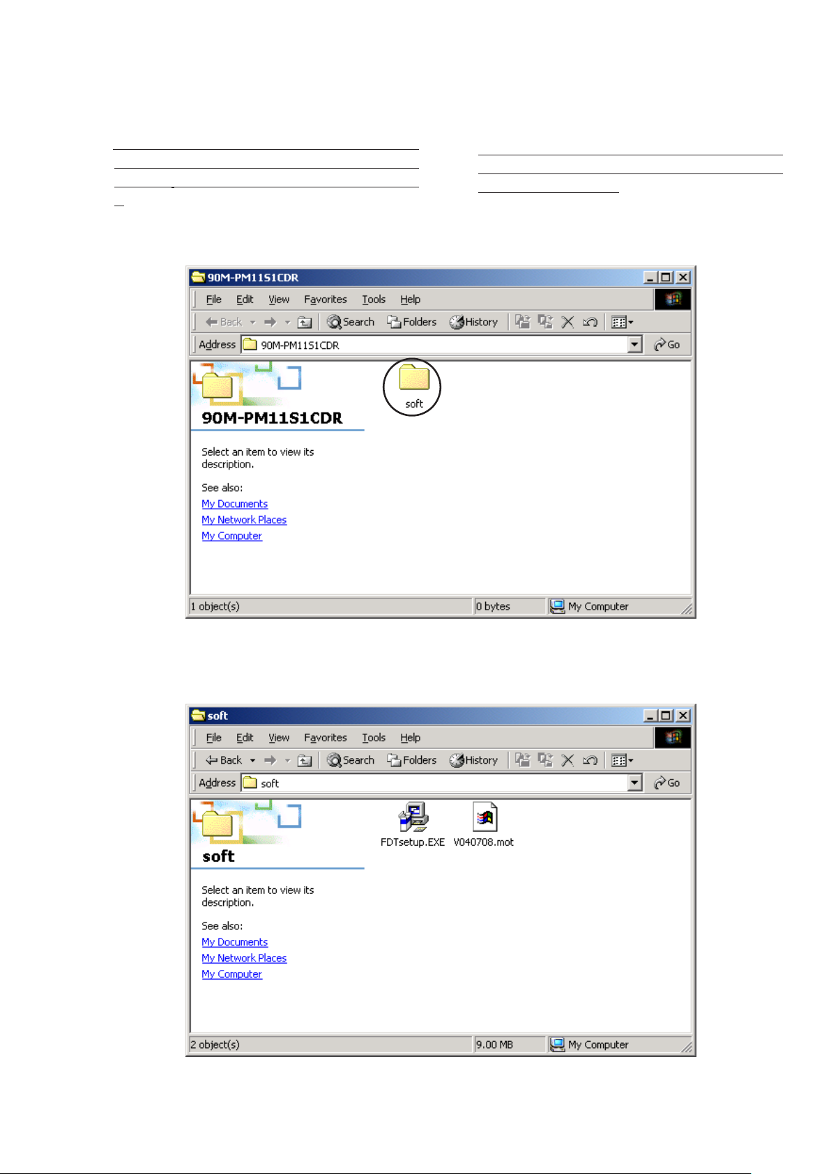
1. Open the CD-ROM (90M-PM15S2CDR) Disc, and double
click soft folder.
説明図について
• 説明図は PM-11S1を使用しています。図中にPM-11S1
と記載されている箇所は PM-KI-PEARL / PM-13S2と置
き換えて操作してください。
1. CD-ROM (90M-PM15S2CDR) の softフォルダをダブル
クリックします。
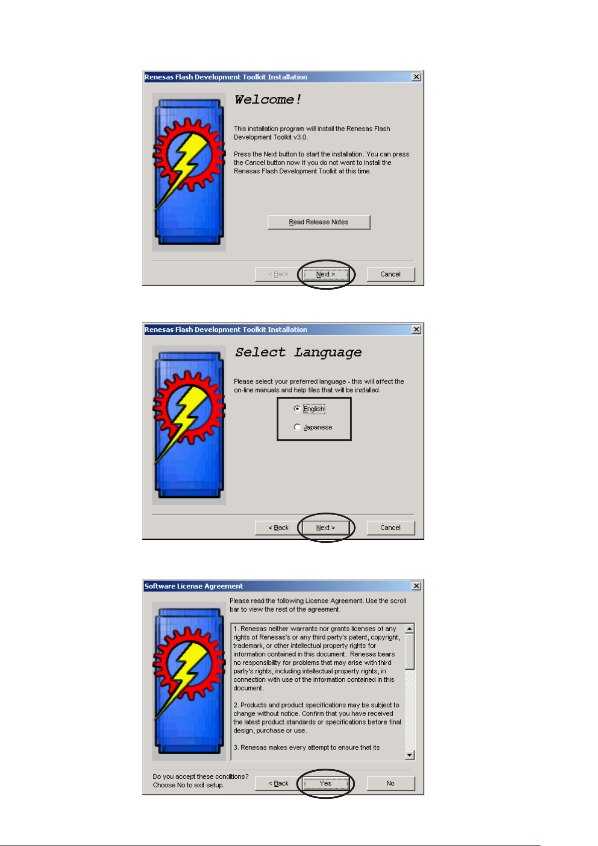
2. Double click the FDT setup.exe.
FDT setup.exe
2.
をダブルクリックします。
10
3. Click Next.
3. インストールウィザードが起動します。
Next
をクリックします。
4. Choose the language. And click Next.
5. Click Yes.
4. 言語を選んで
Yes
5.
をクリックします。
Next
をクリックします。
11
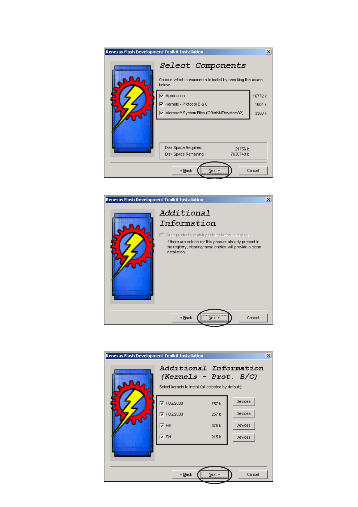
6. Check to the all check boxes. And click Next.
6. チェックボックス全てにチェックが入っていることを確認して
Next
をクリックします。
7. Click Next.
8. Check to the all check boxes. And click Next.
Next
7.
8. チェックボックス全てにチェックが入っていることを確認して
をクリックします。
Next
をクリックします。
12
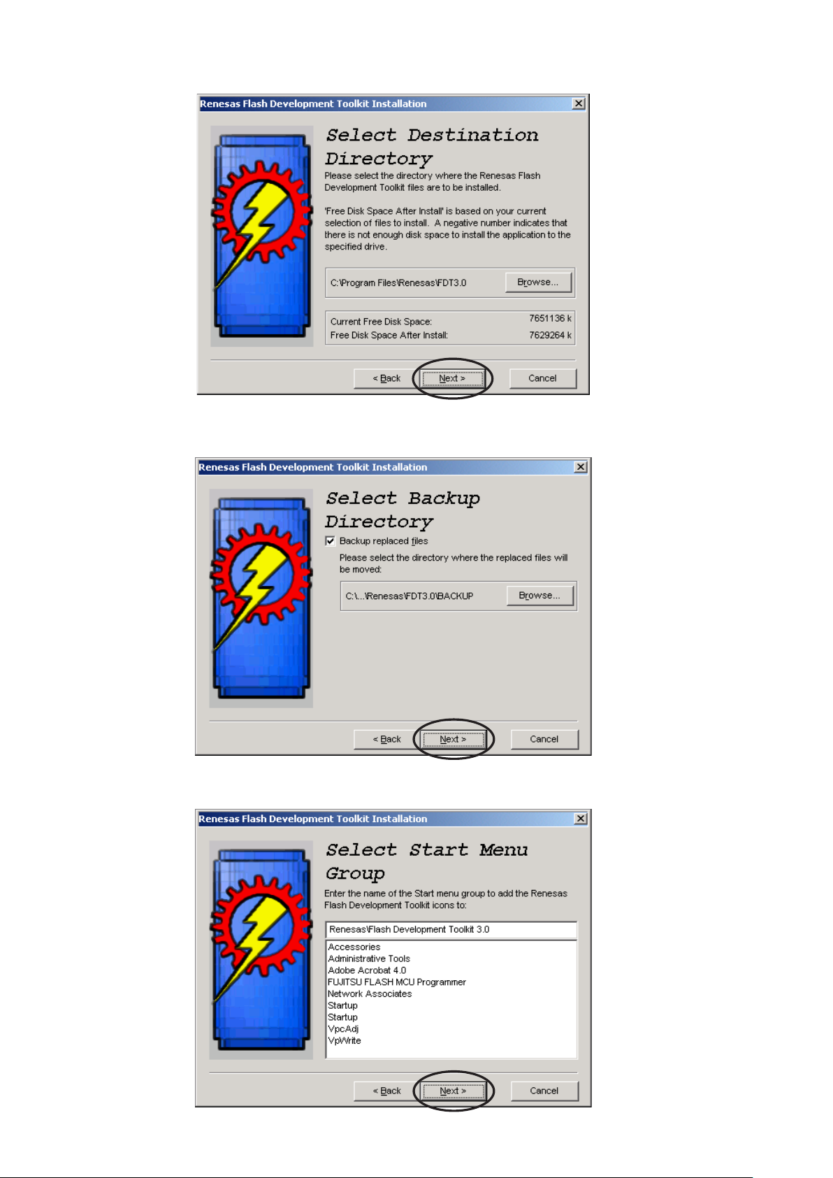
9. Click Next.
9.
Next
をクリックします。
10. Click Next.
11. Click Next.
10.
11.
Next
をクリックします。
Next
をクリックします。
13
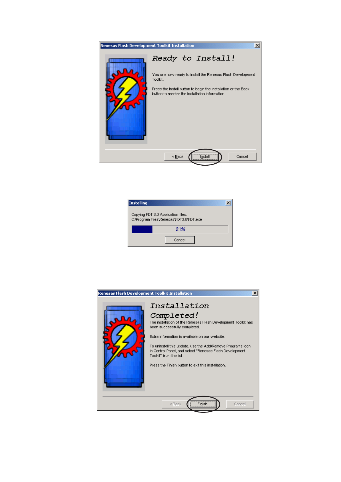
12. Click Install.
12.
Install
をクリックします。
13. The status bar appears.
14. Click Finish.
13. インストールを開始します。
Finish
14.
をクリックして書き込みソフトウェアのインストールを
完了します。
14
6.3. The writing software setup procedure.
6.3. 書き込みソフトウェアの設定
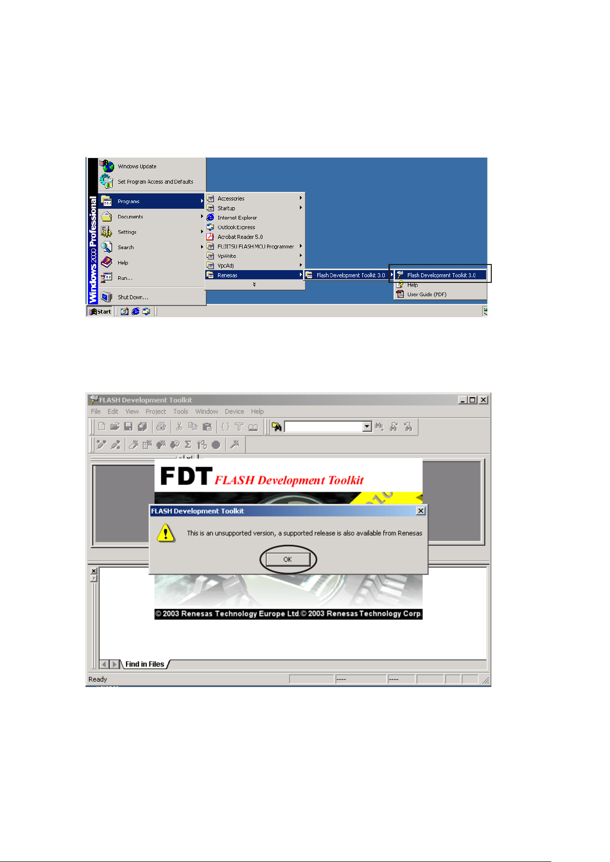
Launch up the writing software.
1. Click Start / Programs / Renesas / Flash Development
Toolkit 3.0 / Flash Development Toolkit 3.0.
2. Click OK. (This window appears at every starting.)
ソフトウェアの起動
Start / Programs / Renesas / Flash Development
1.
Toolkit 3.0 / Flash Development Toolkit 3.0
をクリックします。
2. OKをクリックします。( 起動のたびに下記のコマンドが出ま
すのでその都度OKをクリックしてください。)
15
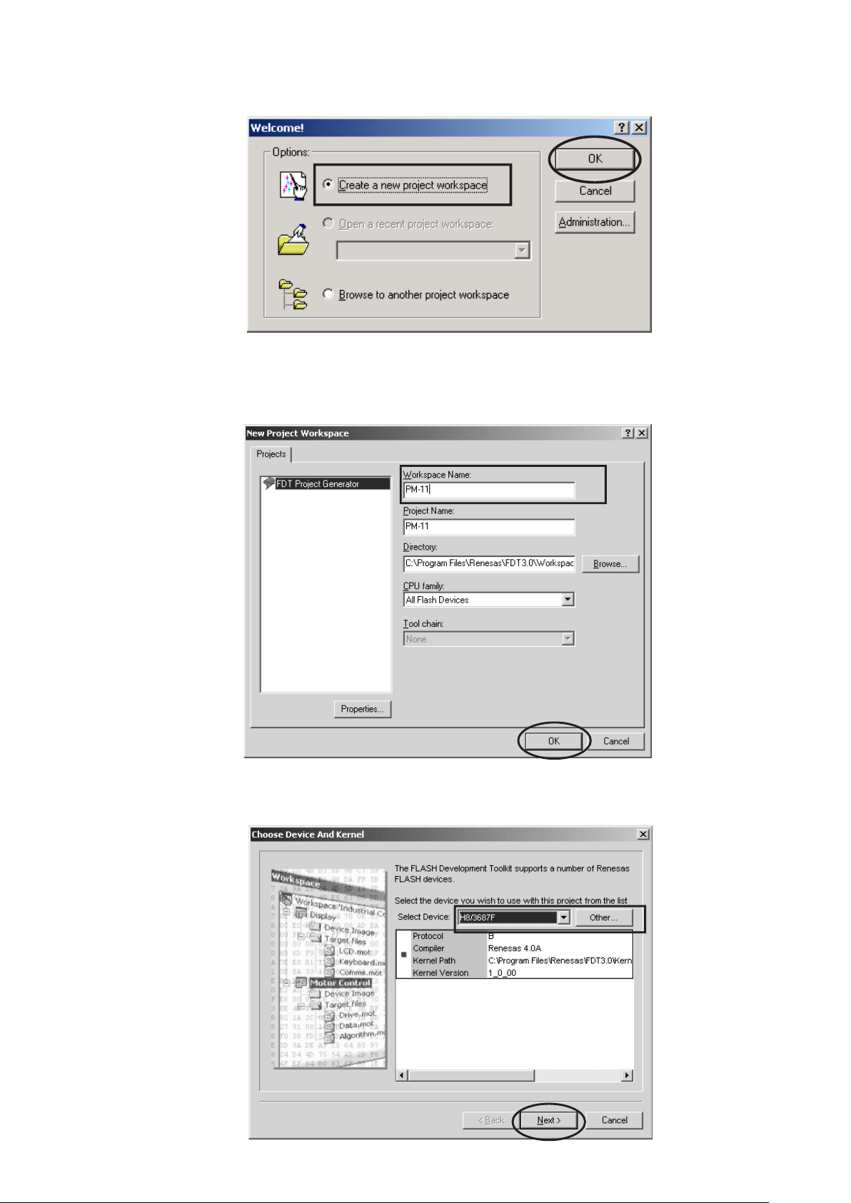
3.
Check Create a new project workspace, and click OK.
Create a new project workspace
3.
をクリックします。
にチェックを入れ、
OK
4. PM-15 is inputted into the Workspace name.
(It is simultaneously inputted into Project Name.)
Click OK.
4. Workspace Nameに
( 同時にProject Nameにも入力されます。)
OK
をクリックします。
PM-15
と入力します。
5. Choose the H8/3687F in Select Device.
Click Next.
5. Select Deviceから
Next
をクリックします。
H8/3687F
を選び、クリックします。
16
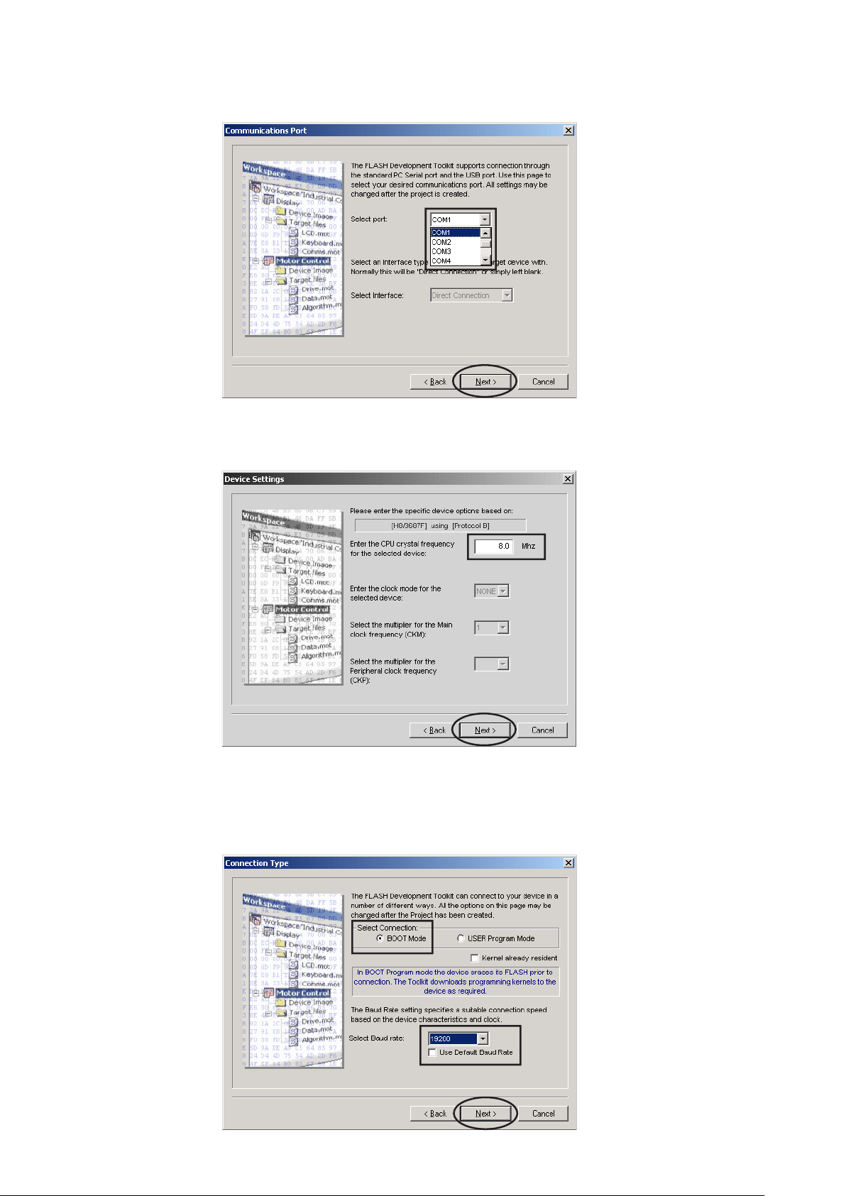
6. Choose the Serial port No. in the Select Port.
Click Next.
6. Select Port から接続する
します。
Next
をクリックします。
Serial Port
番号を選び、クリック
7. 8.0 is inputted into the "Enter the CPU crystal frequency
for the selected device:". Click Next.
8. Check the BOOT Mode in Select Connection.
Choose the 19200 in Select Baud rate. Click Next.
7. "Enter the CPU crystal frequency for the selected
device:"に
8. Select Connection:から
す。Select Baud rate: から
します。
8.0
と入力します。
Next
をクリックします。
BOOT Mode
19200
を選び、
にチェックを入れま
Next
をクリック
Remark :
Please remove check
mark, if it is contained
in Use Default Baud
Rate.
注意 :
Use Default Baud Rate
にチェックが入っていると
Baud Rateを変更できま
せんのでチェックを外し
てください。
17
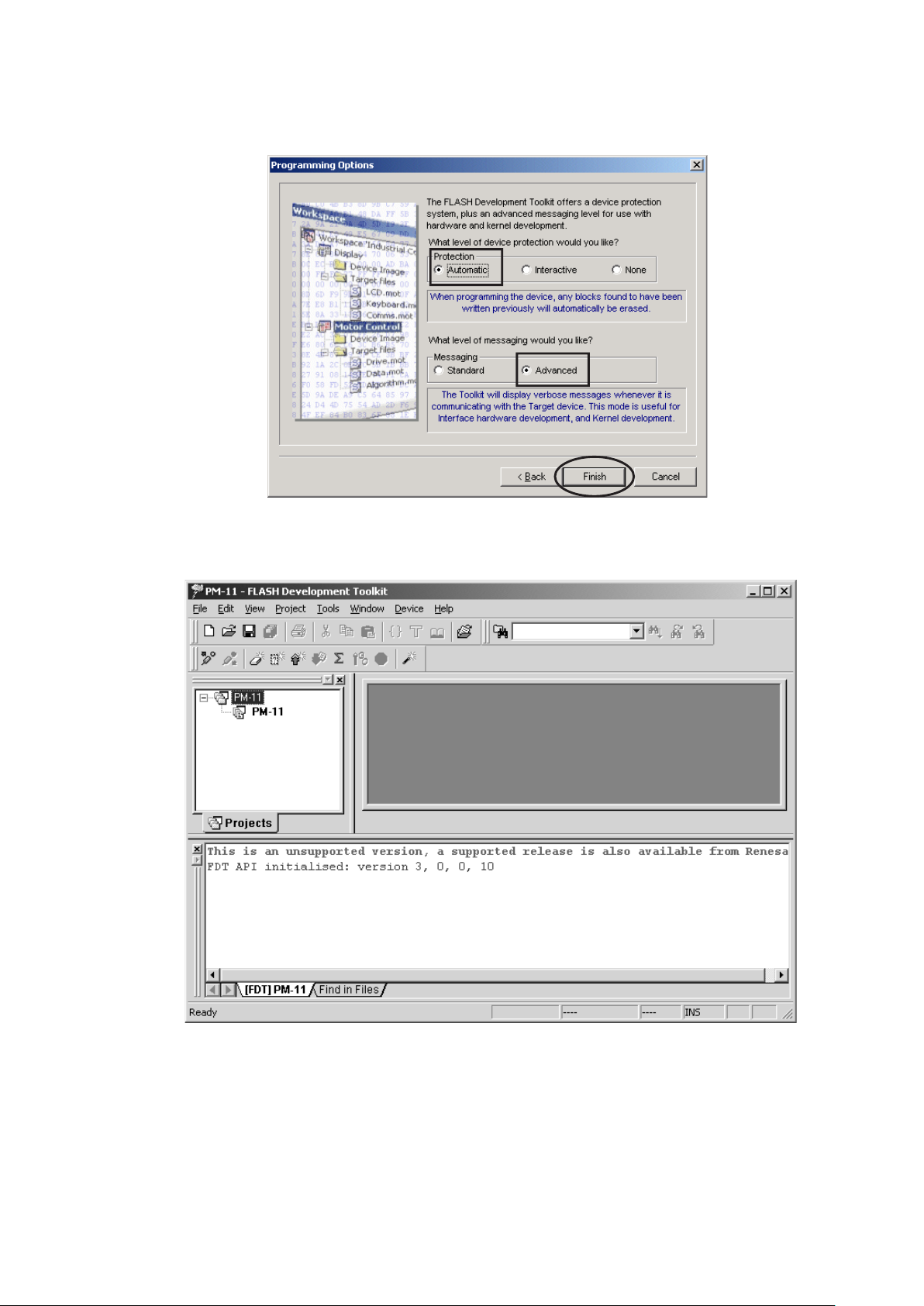
9. Check the Automatic in Protection.
Check the Advanced in Messaging.
Click Finish.
9. Protectionから
Messagingから
Finish
以上で設定は完了です。
をクリックします。
Automatic
Advanced
にチェックを入れます。
にチェックを入れます。
18
6.4. Writing procedure
1. Click Start / Programs / Renesas / Flash Development
Toolkit3.0 / Flash Development Toolkit3.0.
2. Click OK. (This window appears at every starting)
6.4. 書き込み方法
Start / Programs / Renesas / Flash Development
1.
Toolkit3.0 / Flash Development Toolkit3.0
をクリックします。
2. OKをクリックします。(起動のたびに下記のコマンドが出ま
すのでその都度OKをクリックしてください)
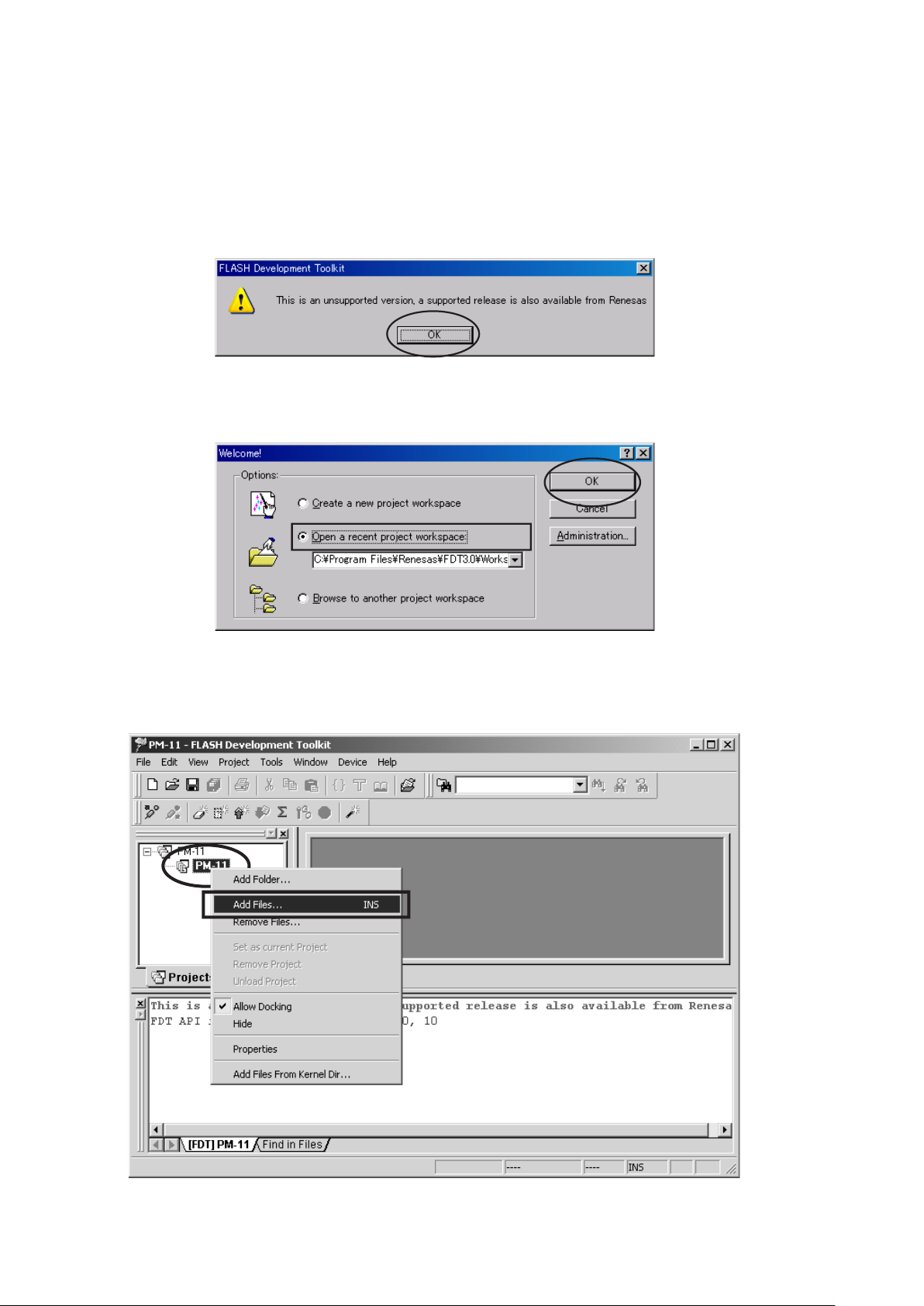
3. Check Open a recent project workspace, and click
OK.
4. The right click PM-15, and Click Add Files....
Open a recent project workspace
3.
OK
をクリックします。
4. 以下の画面が出ましたら、2階層目にある PM-15 のアイコ
ン上で右クリックをして、
Add Files...
にチェックを入れて
をクリックします。
19
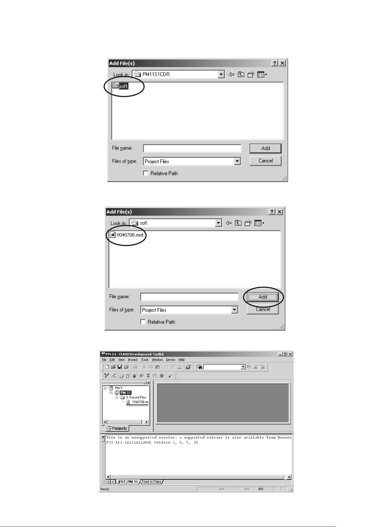
5. Open the CD-ROM (90M-PM15S2CDR) and double click
soft folder.
5. アップデートディスク(90M-PM15S2CDR)の
をダブルクリックします。
soft
フォルダ
6. Select V090507.mot, and Click Add.
7. The holder of V090507.mot is made.
V090507.mot
6.
V090507.mot
7.
を選択し、
のホルダーが出来ます。
Add
をクリックします。
20
8. It checks that PM-KI-PEARL / PM-13S2 and the COM
port are connected by RS232C cable.
8. PM-KI-PEARL / PM-13S2 とWindows PC の COM ポー
トの接続を確認します。
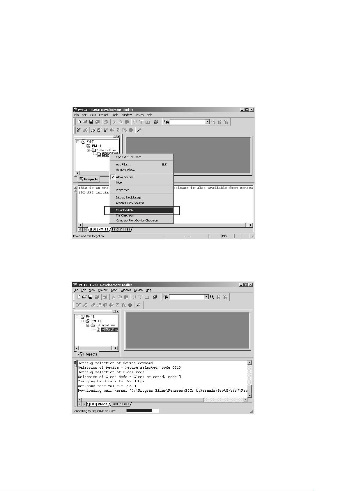
9. Press POWER Button to turn on the unit.
The unit is in the boot mode.( LED and LCD display on
the front panel disappear.)
10. The right click V090507.mot, and Click Download File.
POWER
9.
(この状態より、書き込みモードですが、前面の LED 及び
LCD 表示は消えます。)
10. 4 階層目にある V090507.mot のアイコン上で右クリックを
して
ボタンを押し、Power On 状態にします。
"Download File"
をクリックします。
11. The screen becomes the uploading condition.
When writing is Finished, the below message appears
on the screen.
11. 書き込みが始まると下のような画面が出て状態を表示しま
す。
書き込みが終わると下のような画面が出ます。
 Loading...