

Page 1

PMD371
RS-232 Serial Control
Professional 5 Disc CD Changer
Owners Manual
As found on pages 26-27 of the PMD371
User’s Guide.
Page 2
English
1
The unit can receive external control signals by
connecting a straight cable on the market to the D-sub 9
pin connector for RS232C external control.
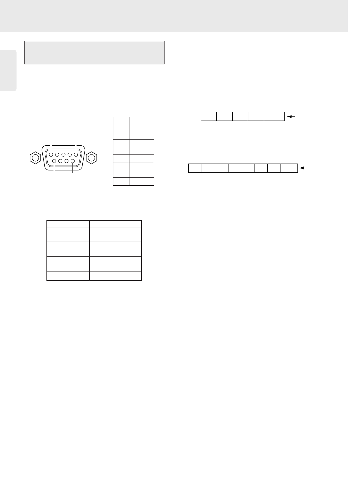
❖ Pin Assignment of the Connector
❖ RS232C Physical Specification
❖ Data Packet
A packet contains data from 5 to 8 bytes in length. In
serial communication, ASCII code from 00h to 7fh is
used. So the HEX data are converted into ASCII code
and set to the data packet. The data packet includes
CR code (0dh) at the end.
Example 1: CD Play (Code: 20 53)
Example 2: T.SIZE (Code 20 104 08)
The unit can identify following commands on next
page.
External Control (Serial Interface)
RS232C
Operations
1NC
2RX
3TX
4NC
5 GND
6NC
7NC
8NC
9NC
Cable Straight-type
Connector D-Sub 9 pin
(Female type)
Baud rate 9600bps
Data bits 8 bits
Parity None
Stop bit 1 bit
Flow control None
RS232C
15
69
[2] [0] [5] [3]
32h 30h 35h 33h 0dh
[2] [0] [1] [0] [4] [0] [8]
32h 30h 31h 30h 34h 30h 38h 0dh
CR code
5 byte
CR code
8 byte
Page 3

English
2
Operations
Key No. Function Code ASCII Code
1 POWER ON/STANDBY 20 12 32h 30h 31h 32h 0dh
2 DISC 20 30 32h 30h 33h 30h 0dh
3 1 20 01 32h 30h 30h 31h 0dh
4 2 20 02 32h 30h 30h 32h 0dh
5 3 20 03 32h 30h 30h 33h 0dh
6 4 20 04 32h 30h 30h 34h 0dh
7 5 20 05 32h 30h 30h 35h 0dh
8 6 20 06 32h 30h 30h 36h 0dh
9 7 20 07 32h 30h 30h 37h 0dh
10 8 20 08 32h 30h 30h 38h 0dh
11 9 20 09 32h 30h 30h 39h 0dh
12 0 20 00 32h 30h 30h 30h 0dh
13 REPEAT (1/ALL) 20 29 32h 30h 32h 39h 0dh
14 A-B (A<->B) 20 59 32h 30h 35h 39h 0dh
15 RANDOM 20 28 32h 30h 32h 38h 0dh
16 PROGRAM (PROG/REV) 20 36 32h 30h 33h 36h 0dh
17 DELETE (DEL/REV) 20 49 32h 30h 34h 39h 0dh
18 INTRO 20 43 32h 30h 34h 33h 0dh
19 PLAY 2 20 53 32h 30h 35h 33h 0dh
20 PAUSE ; 20 48 32h 30h 34h 38h 0dh
21 STOP 9 20 54 32h 30h 35h 34h 0dh
22 PREVIOUS (SKIP) ∞ 20 33 32h 30h 33h 33h 0dh
23 NEXT (SKIP) § 20 32 32h 30h 33h 32h 0dh
24 REW (SEARCH) 5 20 50 32h 30h 35h 30h 0dh
25 FF (SEARCH) 6 20 52 32h 30h 35h 32h 0dh
26 EDIT 20 104 32h 30h 31h 30h 44h 0dh
27 T.SIZE 20 104 08 32h 30h 31h 30h 44h 30h 38h 0dh
28 DIMMER (DISPLAY) 20 71 32h 30h 37h 31h 0dh
29 TIME 20 11 32h 30h 31h 31h 0dh
• Remote Control Unit (RC4300CC) RC-5 Code
The unit can be controlled through its infrared IR sensor on the front panel when it receives remote control
signals that supports RC-5 signals as shown in the table on the following.
These remote control (RC-5) codes can also be used if sent through the RS232C port found on the rear panel
of the unit.
Key No. Function Code ASCII Code
a POWER ON 20 12 01 32h 30h 31h 32h 30h 31h 0dh
b STANDBY 20 12 02 32h 30h 31h 32h 30h 32h 0dh
c DISC 1 20 55 32h 30h 35h 35h 0dh
d DISC 2 20 56 32h 30h 35h 36h 0dh
e DISC 3 20 57 32h 30h 35h 37h 0dh
f DISC 4 20 64 32h 30h 36h 34h 0dh
g DISC 5 20 65 32h 30h 36h 35h 0dh
• Acceptable RC-5 Code
These RC-5 codes are not supported by remote control unit (RC4300CC), but they can also be used if sent
through the RS232C port found on the rear panel of the unit.
 Loading...