

Page 1
Service
PMD351 /N1B/U1B
Manual
TAPE
SECTION PAG E
1. TECHNICAL SPECIFICATIONS ...................................................................................................1
2. SERVICE HINTS AND TOOLS ..................................................................................................... 2
3. TEST EQUIPMENT REQUIRED FOR SERVICING...................................................................... 3
4. ELECTRICAL ADJUSTMENTS .................................................................................................... 3
5. TECHNICAL DESCRIPTION ......................................................................................................10
6. SERVICE PROCEDURE............................................................................................................. 12
7. SERVICE MODE......................................................................................................................... 13
8. WIRING DIAGRAM ..................................................................................................................... 15
9. BLOCK DIAGRAM ...................................................................................................................... 17
10. SCHEMATIC DIAGRAM.............................................................................................................. 19
11. PARTS LOCATION...................................................................................................................... 33
12. MICROPROCESSOR AND IC DATA........................................................................................... 38
13. EXPLODED VIEW AND PARTS LIST......................................................................................... 47
14. ELECTRICAL PARTS LIST ......................................................................................................... 53
Stereo Cassette Deck / Compact Disc Player
HP SELECT
CD
STEREO CASSETTE DECK/COMPACT DISC PLAYER PMD351
QUICK REVERSE
AUTOMATIC TAPE SELECT SYSTEM
DOLBY B-C NR HX PRO
TAPE
PITCH CONT
-
+
CASCADE
CD PITCH CONT.
RESET
MEMO
B
DOLBY NR
REV.MODE
CD-RW PLAYBACK
TIME
0
IR
REC/PAUSE
DUBB.
OFF
C
ON
OFF
ALC
PROGRAM
REPEAT
A-B
EJECT
POWER
TAPE+CD
PHONES
TABLE OF CONTENTS
REC LEVEL
PLAY
PLAY/PAUSE
PLAY PAUSE
STOP
TAPE
PLAY
STOP/EJECT
CD
BALANCE
LR
PMD351
Please use this service manual with referring to the user guide ( D.F.U. ) without fail.
PMD351
R
02AT855010 MIT
First Issue 2003.02
Page 2
MARANTZ DESIGN AND SERVICE
Using superior design and selected high grade components,
Only original
MARANTZ
parts can insure that your
MARANTZ
MARANTZ
product will continue to perform to the specifi cations for which
company has created the ultimate in stereo sound.
it is famous.
Parts for your
MARANTZ
ORDERING PARTS :
equipment are generally available to our National Marantz Subsidiary or Agent.
Parts can be ordered either by mail or by Fax.. In both cases, the correct part number has to be specifi ed.
The following information must be supplied to eliminate delays in processing your order :
1. Complete address
2. Complete part numbers and quantities required
3. Description of parts
4. Model number for which part is required
5. Way of shipment
6. Signature : any order form or Fax. must be signed, otherwise such part order will be considered as null and void.
USA
MARANTZ AMERICA, INC
1100 MAPLEWOOD DRIVE
ITASCA, IL. 60143
USA
PHONE : 630 - 741 - 0300
FAX : 630 - 741 - 0301
AMERICAS
SUPERSCOPE TECHNOLOGIES, INC.
MARANTZ PROFESSIONAL PRODUCTS
2640 WHITE OAK CIRCLE, SUITE A
AURORA, ILLINOIS 60504 USA
PHONE : 630 - 820 - 4800
FAX : 630 - 820 - 8103
EUROPE / TRADING
MARANTZ EUROPE B.V.
P. O. BOX 8744, BUILDING SILVERPOINT
BEEMDSTRAAT 11, 5653 MA EINDHOVEN
THE NETHERLANDS
PHONE : +31 - 40 - 2507844
FAX : +31 - 40 - 2507860
AUSTRALIA
TECHNICAL AUDIO GROUP PTY, LTD
43-53 Bridge Rd.,
STANMORE NSW 2048
AUSTRALIA
PHONE : +61 - (0)2 - 9519 - 0900
FAX : +61 - (0)2 - 9519 - 0600
CANADA
LENBROOK INDUSTRIES LIMITED
633 GRANITE COURT,
PICKERING, ONTARIO L1W 3K1
CANADA
PHONE : 905 - 831 - 6333
FAX : 905 - 831 - 6936
HONG KONG
Jolly ProAudio Broadcast Engineering Ltd.
UNIT 2, 10F, WAH HUNG CENTRE,
41 HUNG TO ROAD, KWUN TONG, KLN.,
HONG KONG
PHONE : 852 - 21913660
FAX : 852 - 21913990
AUSTRALIA
QualiFi Pty Ltd,
24 LIONEL ROAD,
MT. WAVERLEY VIC 3149
AUSTRALIA
PHONE : +61 - (0)3 - 9543 - 1522
FAX : +61 - (0)3 - 9543 - 3677
NEW ZEALAND
WILDASH AUDIO SYSTEMS NZ
14 MALVERN ROAD MT ALBERT
AUCKLAND NEW ZEALAND
PHONE : +64 - 9 - 8451958
FAX : +64 - 9 - 8463554
JAPAN
MARANTZ JAPAN, INC.
35- 1, 7- CHOME, SAGAMIONO
SAGAMIHARA - SHI, KANAGAWA
JAPAN 228-8505
PHONE : +81 42 748 1013
FAX : +81 42 741 9190
Technical
THAILAND
MRZ STANDARD CO., LTD
746 - 754 MAHACHAI ROAD.,
WANGBURAPAPIROM, PHRANAKORN,
BANGKOK, 10200 THAILAND
PHONE : +66 - 2 - 222 9181
FAX : +66 - 2 - 224 6795
TAIWAN
PAI- YUING CO., LTD.
6 TH FL NO, 148 SUNG KIANG ROAD,
TAIPEI, 10429, TAIWAN R.O.C.
PHONE : +886 - 2 - 25221304
FAX : +886 - 2 - 25630415
SHOCK, FIRE HAZARD SERVICE TEST :
SINGAPORE
WO KEE HONG DISTRIBUTION PTE LTD
130 JOO SENG ROAD
#03-02 OLIVINE BUILDING
SINGAPORE 368357
PHONE : +65 6858 5535 / +65 6381 8621
FAX : +65 6858 6078
MALAYSIA
WO KEE HONG ELECTRONICS SDN. BHD.
2ND FLOOR BANGUNAN INFINITE CENTRE
LOT 1, JALAN 13/6, 46200 PETALING JAYA
SELANGOR DARUL EHSAN, MALAYSIA
PHONE : +60 - 3 - 7954 8088
FAX : +60 - 3 - 7954 7088
KOREA
MK ENTERPRISES LTD.
ROOM 604/605, ELECTRO-OFFICETEL, 16-58,
3GA, HANGANG-RO, YONGSAN-KU, SEOUL
KOREA
PHONE : +822 - 3232 - 155
FAX : +822 - 3232 - 154
CAUTION : After servicing this appliance and prior to returning to customer, measure the resistance between either primary AC
cord connector pins ( with unit NOT connected to AC mains and its Power switch ON ), and the face or Front Panel of product and
controls and chassis bottom.
Any resistance measurement less than 1 Megohms should cause unit to be repaired or corrected before AC power is applied, and
verifi ed before it is return to the user/customer.
Ref. UL Standard No. 1492.
In case of diffi culties, do not hesitate to contact the Technical
Department at above mentioned address.
021216MIT
Page 3

1. TECHNICAL SPECIFICATIONS
TAPE DECK
Track System ............................................4 Track, 2 Channel
Recording/Erasure System.......................... AC 105 kHz Bias
Head System (Rotary type combination)
Rec Play Head........................................ Hard Metal Alloy
Erase Head.............................................Dual Gap Ferrite
Motor System
Capstan ................................. DC Servo Controlled Motor
Reel ...................................................................DC Motor
Wow & Flutter
W RMS.................................................................... 0.14%
Frequency Characterstics
Frequency Response (no Dolby NR)
type I (Normal) ..................................... 30Hz-15kHz ±3dB
type II (High) ........................................30Hz-16kHz ±3dB
type IV (Metal) .....................................30Hz-16kHz ±3dB
Overall S/N (no Dolby NR, IEC-A WTD)
type I (Normal) .......................................................... 53dB
type II (High) .............................................................54dB
type IV (Metal) ..........................................................55dB
Dolby NR effect (B/C, S/N improvement, CCIR-ARM WTD)
............................................................... B 9dB, C 18dB
Output Level/Output Impedance.......................... 500mV/1kΩ
Input Sensitivity/Input Impedance
TAPE IN ....................................................... 100mV/47kΩ
MIC IN........................................................... 0.5mV/10kΩ
COMMON PART
Power Supply
/U ...............................................................120V AC 60Hz
/N ...............................................................230V AC 50Hz
Dimensions
Width.................................................. 19 inches (483mm)
Height .......................................... 5 3/16 inches (133mm)
Depth ......................................... 11 1/32 inches (280mm)
Net Weight.......................................................3.1 lbs. (6.8kg)
CD
Channels .............................................................................. 2
Sampling frequency.................................................. 44.1 kHz
Quantization ...........................................16-bit linear/channel
Error correction system ..................... Cross-interleave Reed-
Solomon code (CIRC)
D/A Conversion ........................................1-bit linear/channel
Wow & Flutter................................... Quartz crystal accuracy
Optical Readout System
Laser.............................................AlGaAs semiconductor
Wavelength ........................................................... 780 nm
Frequency Characterstics (Pitch control off)
Frequency Response........................ 20Hz-20kHz ±0.3dB
Dynamic range......................................................... 90 dB
Signal-to-noise ratio.................................................96 dB
Channel separation.................................................. 90 dB
Total harmonic distortion.......................... 0.005% (1 kHz)
Analog output
Output Level............................................2V RMS stereo
Output
Digital output
Coaxial output............................................. 0.5Vp-p/75Ω
Impedance
.............................................................. <1k
Ω
1
Page 4
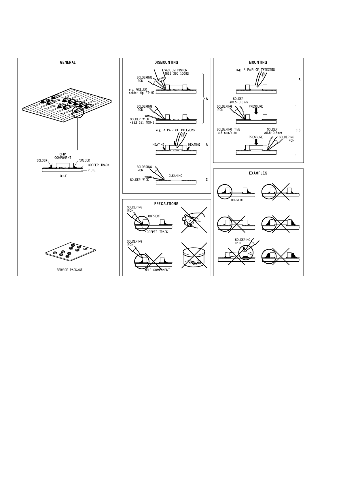
2. SERVICE HINTS AND TOOLS
SERVICE HINTS
SERVICE TOOLS
Audio signals disc 4822 397 30184
Disc without errors (SBC444)+
Disc with DO errors, black spots and fingerprints (SBC444A) 4822 397 30245
Disc (65 min 1kHz) without no pause 4822 397 30155
Max. diameter disc (58.0 mm) 4822 397 60141
Torx screwdrivers
Set (straight) 4822 395 50145
Set (square) 4822 395 50132
13th order filter 4822 395 30204
DVD test disc (PAL) 4822 397 10131
DVD test disc (NTSC) ALMEDIO TDV-540
2
Page 5
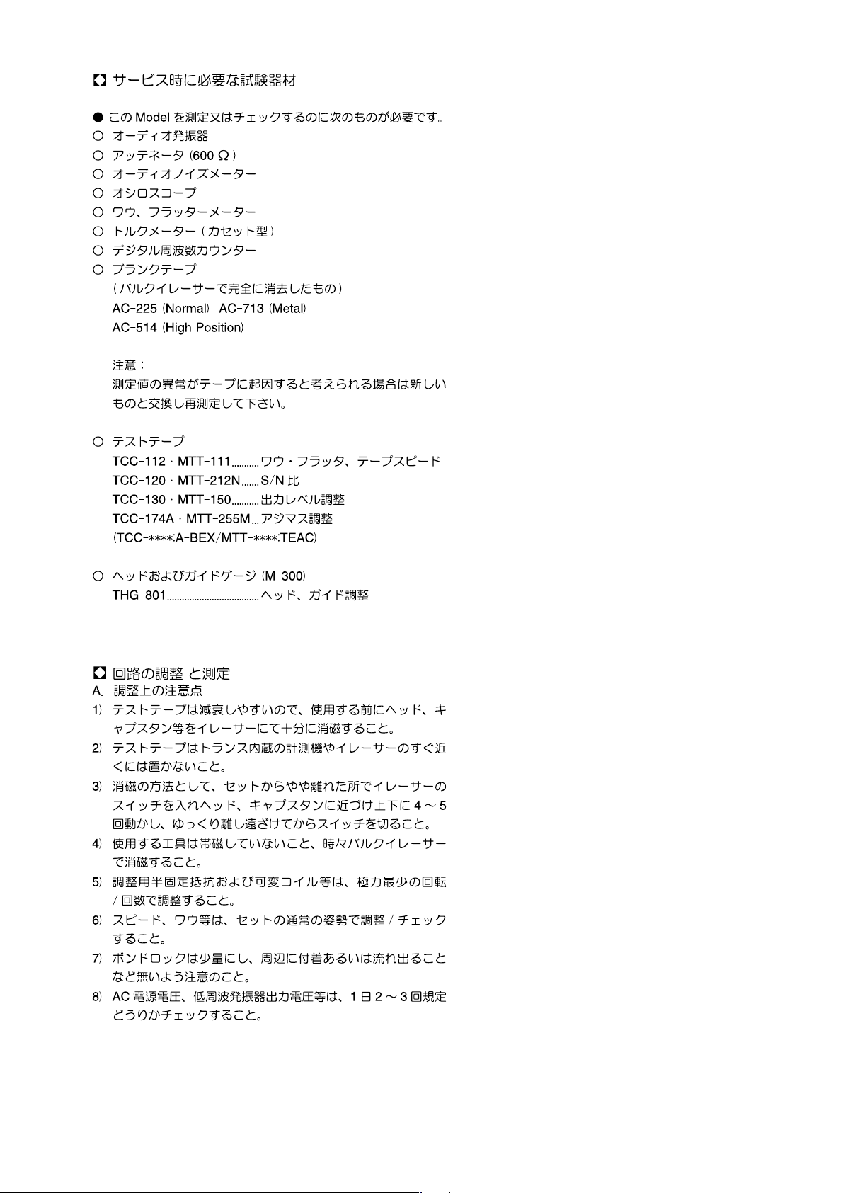
3. TEST EQUIPMENT REQUIRED FOR SERVICING
For measuring or checking a Cassette Deck, the following
instruments and materials are necessary.
• Audio Oscillator (Audio Signal Generator)
• Attenuator (600 ohm)
• Audio Noise Meter
• Oscilloscope
• Wow and Flutter Meter
• Torque Meter (Cassette Type)
• Digital Frequency Counter
• Test Tape
TCC-112/MTT-111 Wow/Flutter, Tape Speed
TCC-120/MTT-212N Signal-to-Noise Ratio
TCC-130/MTT-150 Dolby Level Adjustment
TCC-174A/MTT-255M Azimuth Adjustment
(TCC-
• Blank Tapes (Completely erased with bulk eraser)
AC-225 (Normal)
AC-514 (High Position)
AC-713 (Metal)
NOTE:
If any doubt is noted in a measured value, which is due to a
tape. Re-measurement is necessary by use the new tape.
:A-BEX/MTT-
****
****
:TEAC)
• Mirror cassette 12um padless
TCC-902/MTT-902 Tape fl owing check
• Head guide gauge (M-300)
THG-801
4. ELECTRICAL ADJUSTMENTS
(A) Remark for adjustment
1) Clean and de-magnetize the tape path part before
measurement.
2) Keep cassette tapes away from equipments.
3) De-magnetize tools often.
4) Do not turn adjustment parts by strong force.
5) Keep a cassette deck horizontally while measuring.
6) Keep amount of glue in proper.
7) Confi rm the mains voltage, output level of oscillator and
etc. before adjustment and measurement.
3
Page 6
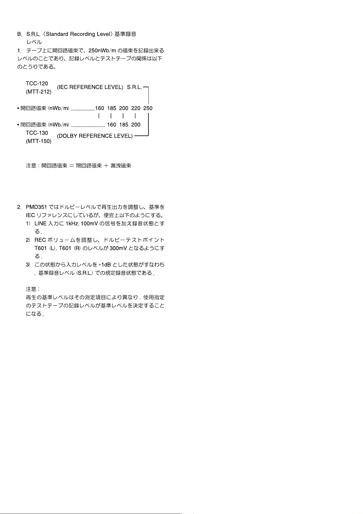
(B) S.R.L. (Standard Recording Level)
1. The Standard Recording Level is a signal of 250nWb/m
on a tape at *OPEN CIRCUIT MAGNETIC FLUX.
The relation between the recording level and a test tape
is as follows.
• OPEN CIRCUIT 160 185 200 220 250
MAGNETIC FLUX
(nWb/m)
• CLOSED CIRCUIT 160 185 200
MAGNETIC FLEX
(nWb/m) **
(*): OPEN CIRCUIT MAGNETIC FLUX = CLOSED
CIRCUIT MAGNETIC FLUX + LEAK
MAGNETIC FLUX.
(**): TCC-130 (DOLBY REFERENCE LEVEL)
(MTT-150)
(***): TCC-120 (IEC REFERENCE LEVEL) (S.R.L.)
(MTT-212N)
2. S.R.L. Setting
1) Apply a 1kHz, 100mV to the LINE INPUT jacks.
2) Put the unit in RECORD mode and adjust the REC
LEVEL control to obtain the following level of signal at
the DOLBY test points T601 (L), T602 (R) 300mV.
3) Adjust the output of the audio oscillator applied to the
LINE INPUT jacks to 112.2mV (+1dB). This is the rated
recording condition for the STANDARD RECORDING
LEVEL.
***
4
Page 7
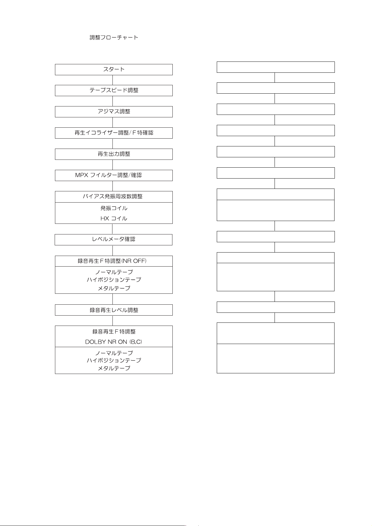
ADJUSTMENT FLOW CHART
Start
TAPE SPEED Adjustment
AZIMUTH Adjustment
PLAY-BACK EQ Adjustment or Check
PLAY-BACK LEVEL Adjustment
MPX Filter Adjustment
BIAS FREQUENCY Adjustment
BIAS OSC Coil
HX Coil
LEVEL METER Sensitivity Check
REC/PB FREQUENCY Response Adjust.
NORMAL Tape
HIGH POSITION Tape
METAL Tape
REC/PB LEVEL Adjustment
REC/PB FREQUENCY Response check
DOLBY NR ON (B,C)
NORMAL Tape
HIGH POSITION Tape
METAL Tape
5
Page 8
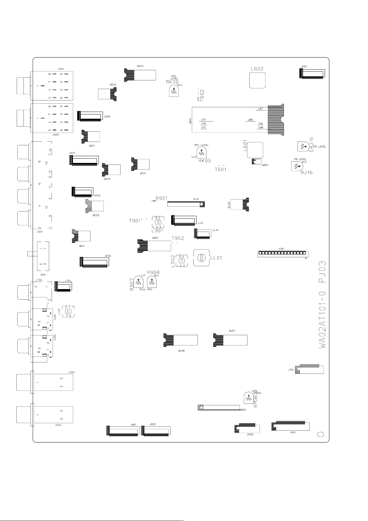
ADJUSTMENT POINT COMPONENT SIDE
6
Page 9
4.1 TAPE SPEED ADJUSTMENT
1) Playback the middle part of the Wow & Flutter test tape.
2) Adjust the variable resistor.
ADJUSTMENT POINT
RM36
for 3000Hz (2990Hz - 3010Hz).
3) Repeat 1) and 2) for both directions.
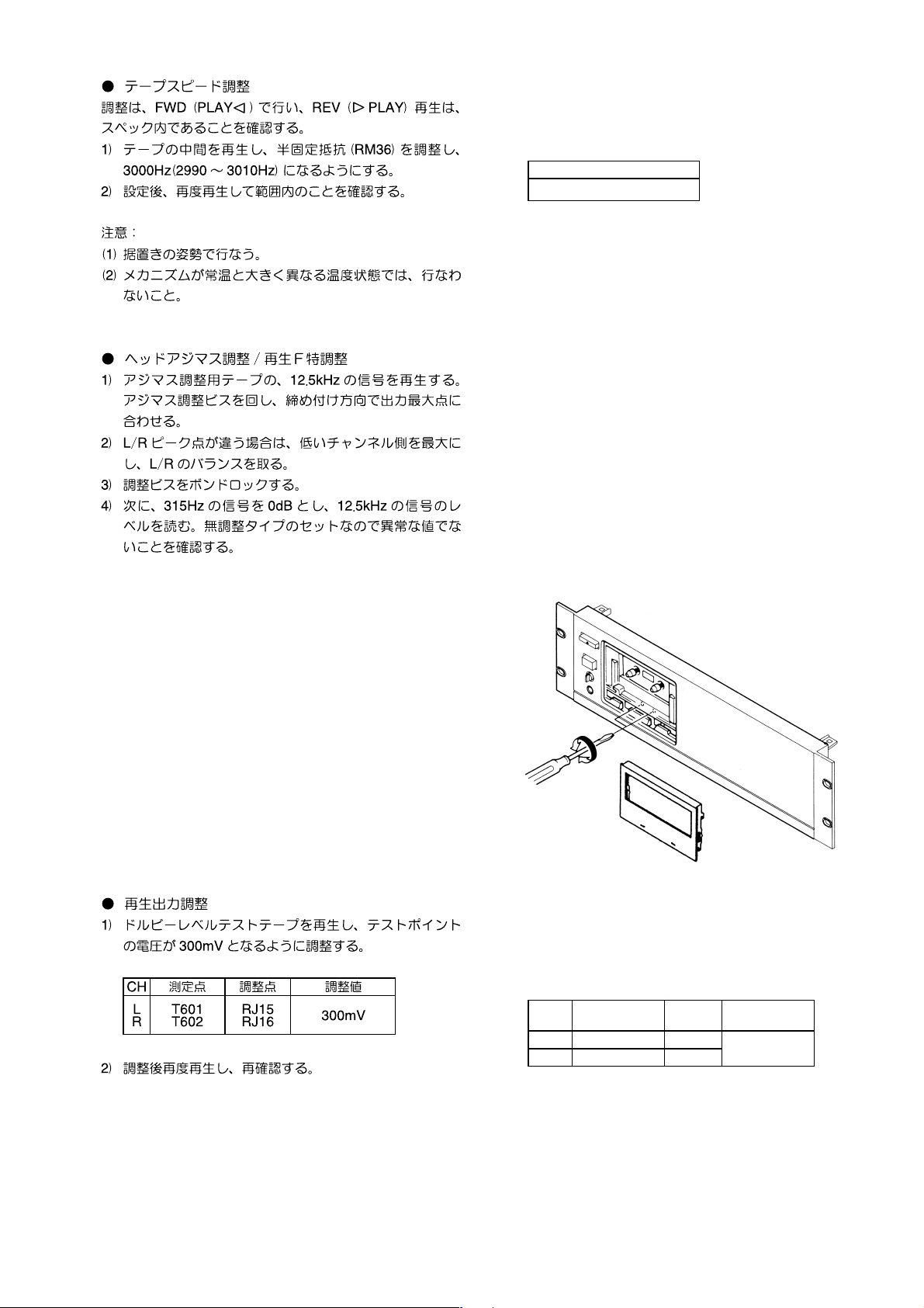
4.2 HEAD AZIMUTH ADJUSTMENT and
FREQUENCY RESPONSE CHECK
1) Playback the 12.5 kHz part of the Azimuth test tape.
2) Adjust the proper azimuth screw in both directions for
maximum output at the LINE OUTPUT jacks.
3) In case the L/R peak points are different, adjust the
lower channel to the maximum.
4) Lock azimuth screws with glue.
5) Playback the 315 Hz part of the test tape and set a 0 dB
ref., then playback the 12.5 kHz part of the test tape and
confi rm that the output is 0 dB, ±3 dB.
4.3 PLAYBACK LEVEL ADJUSTMENT
1) Playback the DOLBY test tape, adjust the following
variable resistors to the values and the test points
indicated below:
ADJ.
CH TEST POINT
L T601 RJ15
R T602 RJ16
RES.
2) After adjustment, replay and check it again.
Remark:
In case of drifting output during replay, check that the tape
running and the test tape are ok, because they may be
defective.
7
ADJUSTMENT
VALUE
300mV
Page 10
4.4 MPX FILTER ADJUSTMENT
1) Put the unit in REC mode with a S.R.L. input.
2) The MPX fi lter switch ON and change the input
frequency to 19kHz(±10Hz).
3) Adjust L601(L), L602(R) for minimum output at the LINE
OUTPUT jacks.
CH ADJ. POINT ADJ. TO
L
R
L601
L602
Minimum
4.5 RECORDING BIAS FREQUENCY AND HX COIL
ADJUSTMENT
1) Put the unit in REC mode.
2) Adjust the following bias oscillator coil for 105kHz at the
bias frequency.
TEST POINT ADJ. POINT ADJ. TO
R901 LL01 105kHz
Remark:
May have to connect FREQUENCY COUNTER through an
AUDIO VOLT METER.
3) Next, connect the Oscilloscope to the HX test point
(T901, T902).
4) Adjust the HX coils for minimum level.
CH TEST POINT COIL ADJ. TO
L
R
T901
T902
L901
L902
Minimum
4.6 LEVEL METER SENSITIVITY CHECK
1) Put the unit in REC mode with a 1kHz, 100mV signal to
the LINE INPUT jacks.
2) Set the REC LEVEL at the test point T601, T602 as
300mV.
3) Check the VU LEVEL METER indicates 0dB.
Remark:
Dolby switch has to be OFF.
8
Page 11
4.7 REC/PLAYBACK FREQUENCY RESPONSE
ADJUSTMENT
1) Adjust the output level of the audio oscillator to 5.0mV
(-26dB) from the S.R.L. recording condition.
Record 400Hz and 12.5kHz signals with DOLBY OFF.
2) Playback the recorded part and confi rm the level of
differences between 400Hz and 12.5kHz are within ±
1.0dB. If the level difference is out of allowance, adjust
the variable resistor and confi rm the playback level of
rerecording
CH. ADJUSTMENT
L
R
R907
R908
3) Repeat steps #1 and 2 with High Position and METAL
type tapes for confi rmation.
4.8 REC/PLAYBACK LEVEL ADJUSTMENT
1) Input the 400Hz signal and put the unit into record
mode. Measure the output level to set the reference
level of 0dB.
2) Playback the just recorded part and adjust proper
variable resistor, until the REC/PB levels are within
±0.5dB.
CH. ADJUSTMENT
L
R
RK05
RK06
3) Repeat steps #1 and 2 with High Position and METAL
type tapes for confi rmation.
4.9 REC/PLAYBACK FREQUENCY RESPONSE
CHECK DOLBY NR
1) Adjust the output level of the audio oscillator to 5.0mV
(-26dB) from the S.R.L. recording condition.
Record the following signals with DOLBY-B ON and
Normal tape at 250Hz, 1kHz, 3kHz, 6.3kHz, 10kHz and
12.5kHz.
2) Playback the just recorded part and confi rm the
difference of levels are within ±1.0dB.
3) Repeat steps #1 and 2, with High Position and METAL
type tapes.
4) Repeat steps #1 and 2, with Dolby-C ON.
9
Page 12

5. TECHNICAL DESCRIPTION
How to use the RS-232C connector
This input/output connector (D-Sub 9-pin female) is used for
RS-232C external control.
A straight cable available on the market can be connected to
this connector to exercise external control and send status
information.
• Connector pin assignment
1NC
69
51
• RS232C Connection
PMD351 Typical HOST
Transmit Data
Receive Data
Ground
RS in
CS out
2
3
5
7
8
D-Sub 9 Pin
(male)
D-Sub 9 Pin
The wiring requirements for a 9 pin to 9 pin serial
con nec tion, are a male to female straight cable.
• RS-232C physical specifi cations
Cable Straight cable
Baud rate 9600 bps
Data bits 8 bits
Parity bit None
Stop bit 1 bit
Flow control CS/RS Hardware Flow
2TX
3RX
4NC
5 GND
6NC
7RTS
8 CTS
9NC
Rx Data
2
Tx Data
3
5
Ground
7
RTS send
8
CTS receive
(female)
Example
:
Reception Time Command (code
@1
2011
)
[@][1][2][0][1][1][CR]
0x40 0x31 0x32 0x30 0x31 0x31 0x0d
When transmitting commands consecutively, put more
than 100ms blank between commands.
Received command data
Command CD Command TAPE Command
0 "@12000"+CR "@11800"+CR
1 "@12001"+CR "@11801"+CR
2 "@12002"+CR "@11802"+CR
3 "@12003"+CR "@11803"+CR
4 "@12004"+CR "@11804"+CR
5 "@12005"+CR "@11805"+CR
6 "@12006"+CR "@11806"+CR
7 "@12007"+CR "@11807"+CR
8 "@12008"+CR "@11808"+CR
9 "@12009"+CR "@11809"+CR
Time "@12011"+CR
Recall "@12015"+CR
Repeat "@12029"+CR
Next "@12032"+CR "@11832"+CR
Previous "@12033"+CR "@11833"+CR
Pitch Reset "@12037"+CR
Pitch Up Start "@12038"+CR
Pitch Up Stop "@1203801"+CR
Pitch Down Start "@12039"+CR
Pitch Down Stop "@1203901"+CR
Program/Memo "@12041"+CR "@11841"+CR
AMS "@12043"+CR "@11843"+CR
Open/Close "@12045"+CR
Pause "@12048"+CR "@11848"+CR
Clear "@12049"+CR
Fast Backward Start "@12050"+CR "@11850"+CR
Fast Backward Stop "@1205001"+CR
Fast Forward Start "@12052"+CR "@11852"+CR
Fast Forward Stop "@1205201"+CR
Play "@12053"+CR "@11853"+CR
Stop "@12054"+CR "@11854"+CR
A-B "@12059"+CR
Direction "@11847"+CR
REC Mute "@11842"+CR
REC "@11855"+CR
• Command reception
The command packets have a data length of 7 - 10 bytes.
ASCII codes from 0x00 to 0x7f are used to receive serial
data. At the transmission end, therefore, take steps to
convert the ASCII codes into HEX data to set the data in
the data packets. CR (0x0d) is added as the data packet
delimiter.
10
Page 13
• Status confi rmation command
When to confi rmation of the RS232C operations, the
following Status transmitting requirement commands is
transmitted to PMD351, status condition is replies.
• Status transmission
The status packets have a fi xed data length of 8 bytes.
ASCII codes from 0x00 to 0x7f are used to transmit serial
data. For this reason, the ASCII codes are converted
into HEX data before the data is set in the data packets
and transmitted. CR (0x0d) is added as the data packet
delimiter.
Request Command for CD Response from CD
Power "@1?20POWE"+CR
TrayMode "@1?20TRAY"+CR
PlayMode "@1?20PLAY"+CR
Disc "@1?20DISC"+CR
RepeatMode "@1?20RPTM"+CR
TimeMode "@1?20TMOD"+CR
Album "@1?20ALBU"+CR "@120Axxx"+CR
Track "@1?20TRAC"+CR "@120Txxx"+CR
Current Display
Time
Request Command for TAPE Response from TAPE
Power "@1?18POWE"+CR
Cassette "@1?18CASS"+CR
PlayMode "@1?18PLAY"+CR
Current Display
Time
Memo "@1?18MEMO"+CR
"@1?20TIME"+CR "@120xxxx"+CR
"@1?18TIME"+CR "@118xxxx"+CR
Standby "@120POFF"+CR
PowerOn "@120PRON"+CR
Open "@120OPEN"+CR
Close "@120CLOS"+CR
Toc Reading "@120TOCR"+CR
Stop "@120STOP"+CR
Play "@120PLAY"+CR
Pause "@120PASE"+CR
FF "@120FASF"+CR
REW "@120FASR"+CR
NoDisc "@120NODI"+CR
ERROR "@120ERDI"+CR
CDDA "@120CDDI"+CR
MP3 "@120MPDI"+CR
OFF "@120RTOF"+CR
ONE "@120RTON"+CR
ALL "@120RTAL"+CR
A- "@120RTA-"+CR
A-B "@120RTAB"+CR
Track "@120TTRA"+CR
TrackRem "@120TTRE"+CR
TotalRem "@120TREM"+CR
TotalLap "@120TTLA"+CR
Standby "@118POFF"+CR
PowerOn "@118PRON"+CR
IN "@118CAIN"+CR
Eject "@118CAEJ"+CR
Stop "@118STOP"+CR
PlayFW "@118PLFW"+CR
PlayRV "@118PLRV"+CR
Pause "@118PASE"+CR
FF "@118FASF"+CR
REW "@118FASR"+CR
Cue "@118CUE_"+CR
Review "@118REVI"+CR
Rec "@118RECO"+CR
Rec Pause "@118RECP"+CR
OFF "@118MEOF"+CR
ON "@118MEON"+CR
Example
1:
Transmission Power On (code
[@][1][2] [0] [P][R][O][N][CR]
@1
20PRON
0x40 0x31 0x32 0x30 0x50 0x57 0x4f 0x4e 0x0d
Transmitted status data
Category Status from CD
Power
TrayMode
PlayMode
Disc
RepeatMode
TimeMode
Category Status from TAPE
Power
Cassette
PlayMode
Memo
Standby "@120POFF"+CR
PowerOn "@120PRON"+CR
Open "@120OPEN"+CR
Close "@120CLOS"+CR
Toc Reading "@120TOCR"+CR
Stop "@120STOP"+CR
Play "@120PLAY"+CR
Pause "@120PASE"+CR
FF "@120FASF"+CR
REW "@120FASR"+CR
NoDisc "@120NODI"+CR
ERROR "@120ERDI"+CR
CDDA "@120CDDI"+CR
MP3 "@120MPDI"+CR
OFF "@120RTOF"+CR
ONE "@120RTON"+CR
ALL "@120RTAL"+CR
A- "@120RTA-"+CR
A-B "@120RTAB"+CR
Track "@120TTRA"+CR
TrackRem "@120TTRE"+CR
TotalRem "@120TREM"+CR
TotalLap "@120TTLA"+CR
Standby "@118POFF"+CR
PowerOn "@118PRON"+CR
IN "@118CAIN"+CR
Eject "@118CAEJ"+CR
Stop "@118STOP"+CR
PlayFW "@118PLFW"+CR
PlayRV "@118PLRV"+CR
Pause "@118PASE"+CR
FF "@118FASF"+CR
REW "@118FASR"+CR
Cue "@118CUE_"+CR
Review "@118REVI"+CR
Rec "@118RECO"+CR
Rec Pause "@118RECP"+CR
OFF "@118MEOF"+CR
ON "@118MEON"+CR
)
11
Page 14
6. SERVICE PROCEDURE
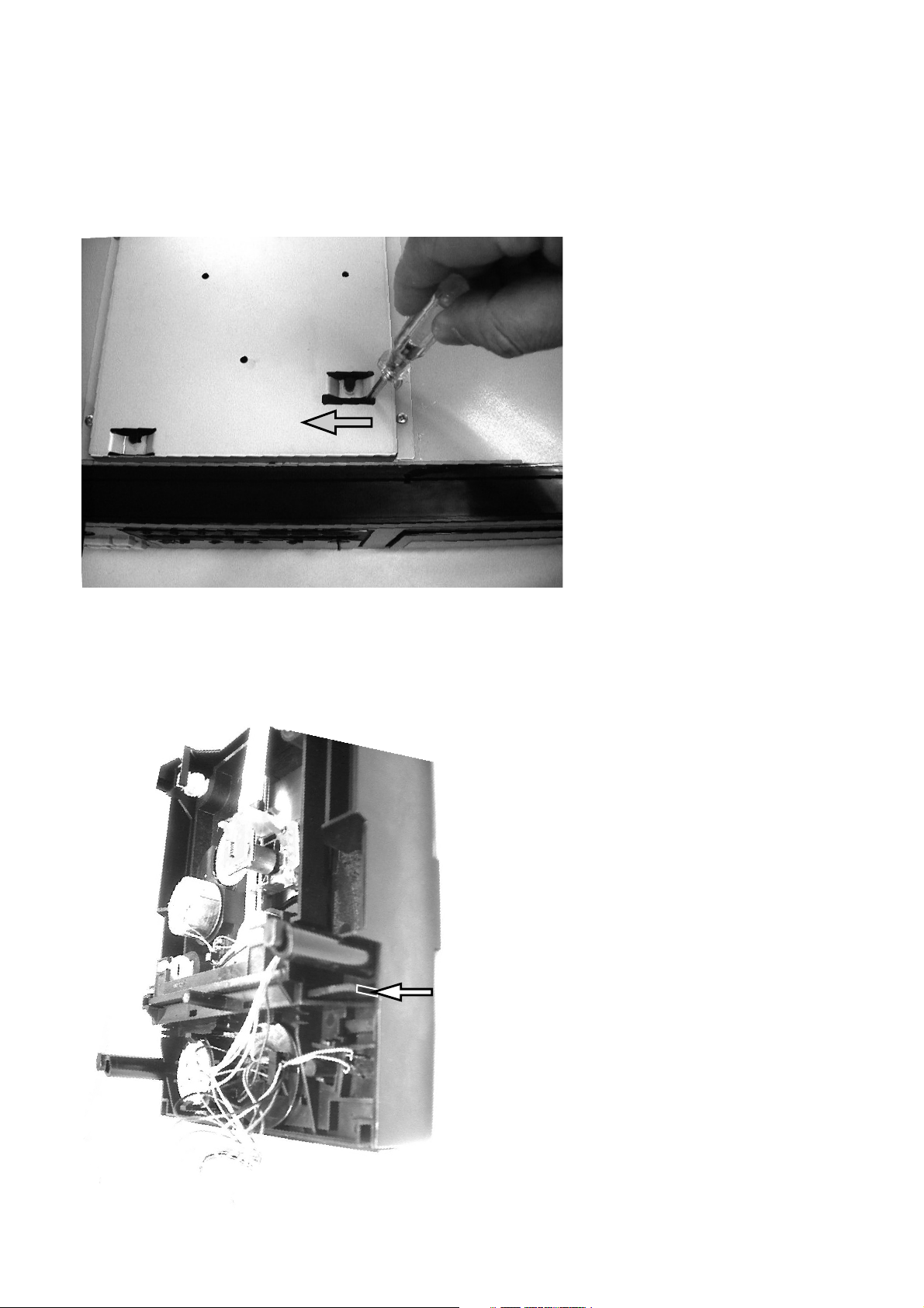
Emergency Eject
1. To open the stucked tray, insert a minus driver into the hole of bottom and push the eject lever.
2. Use a minus driver. (width is about 4 mm)
This picture shows the unit upside down. The eject lever is pointed by the arrow.
The lever is thin so aim the narrow area carefully.
12
Page 15
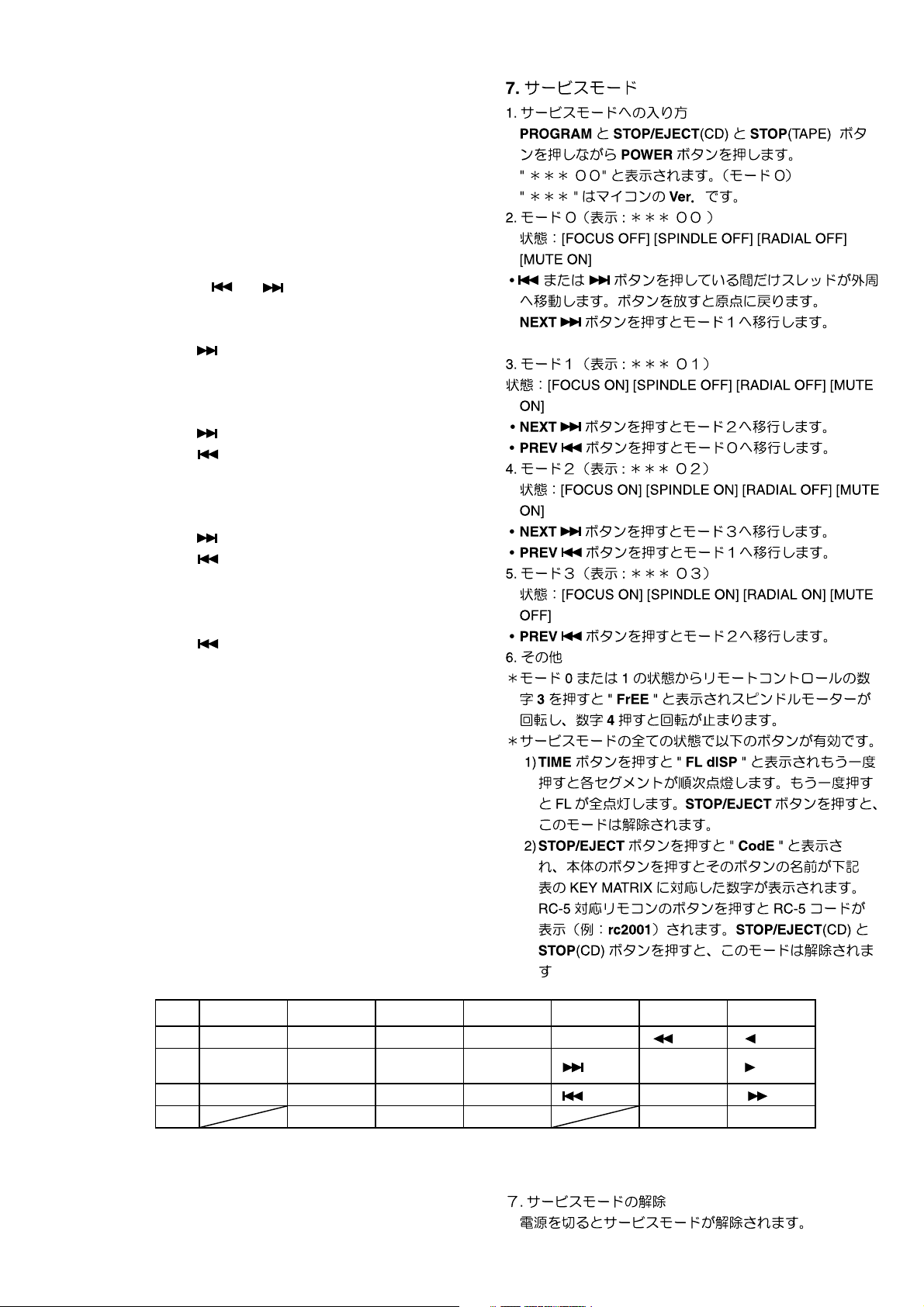
7. SERVICE MODE
1. How to enter into the Service Mode
While pressing PROGRAM, STOP/EJECT(CD) and
STOP(TAPE) buttons, press POWER button.
"
00 " is diaplayed
***
"
" is Version number of the microprocessor.
***
2. Mode0 (Display :
Status: [FOCUS OFF] [SPINDLE OFF] [RADIAL OFF]
[MUTE ON]
• While pressing
toward the outer edge. Release the button makes the
sledge return to the origin.
Press NEXT button to go to Mode 1.
3. Mode 1 (Display :
Status: [FOCUS ON] [SPINDLE OFF] [RADIAL OFF]
[MUTE ON]
• Press NEXT button to go to Mode 2.
• Press PREV button to go to Mode 0.
4. Mode 2 (Display :
Status: [FOCUS ON] [SPINDLE ON] [RADIAL OFF] [MUTE
ON]
• Press NEXT button to go to Mode 3.
• Press PREV button to go to Mode 1.
5. Mode 3 (Display :
Status: [FOCUS ON] [SPINDLE ON] [RADIAL ON] [MUTE
OFF]
• Press PREV button to go to Mode 2.
6. Others
* In the Mode 0 or 1, pressing the number button 3 on the
remote makes the spindle motor rotate and "FrEE" is
displayed. Press the number button 4 to stop rotation.
* In this Service Mode, all of the following button functions
work in any status.
1) Press TIME button, " FL dISP " is displayed. Press
it again then each FL segment lights up one by one.
Press it again then light up all the FL segments. Press
STOP/EJECT button to go to Mode 0
2) Press STOP/EJECT button, " CodE " is displayed.
Then press a button on the unit. The name of the button
is displayed. Pressing a button on the Remote controler
for RC-5 unit display the RC-5 code (Ex. : rc2001) of
the button. Press STOP/EJECT(CD) and STOP(CD)
button to go to Mode 0.
00 )
***
and buttons, the sledge moves
01)
***
02)
***
03)
***
6543210
1 PITCH + TIME One-way mode MEMO STOP/EJECT
2 PITCH 0 REPEAT
3 PITCH - PROGRAM CASCADE ALC ON
4 A-B DOLBY-C DOLBY-B DUBB. REC/PAUSE
Ex.: Press
PITCH +
button,
"1-6"
is displayed.
7. Terminating Service Mode
Turn off power to quit Service Mode.
Continuous
mode
RESET
13
(REW) (PLAY)
(NEXT) STOP (PLAY)
(PREV) PLAY/PAUSE (FF)
Page 16

Personal notes:
14
Page 17

8. WIRING DIAGRAM
TO CD MECHA
TO
CD
MECHA
TO CASSETTE MECHA
15 16
Page 18

9. BLOCK DIAGRAM
AC IN
VAM2202
Mic Input
0.5mV/10K
Line Input
100mV/47K
PT03
Power
Trans.
PS03
Power
Switch
PJ03 MAIN PCB
Q802
Amp
J803
SW
DC
3.3V
15V
12V
8V
CD5V
5V
- 25V
CD Block
RF AMP &
Laser Supply
TZA1024
PG03
REC
VOLUME
Mix
PS01
MP3 Decoder
Control
SAA7324/M2
Cassette Block
EQ AMP
NJM2068
Dolby B/C & REC EQ AMP
HA12155NT (+15V)
uP Block
Micro Processor
uPD784217-8EU
X'TAL
RESET
DAC
CS4338
R/P SWITCH
uPC1330(15V)
16MHz
HXPRO
uPC1297
AUTO REVERSE
R/P HEAD APE MECHANISM
ALPS CMAY2Z3
E-HEAD/
Motor Drive/Ta
pe count ...
Max
PV03
H-Phone
SW/AMP
PP03
RS232C 2Way
01
LT
PY03
IR
FL Driver
uPD16311
Tape Out
(500mV/470Ω)
Mix Out
CD Out
(2Vrms/600Ω)
H-Phone Out
Remote
Digital Out
0.5V
pp/75Ω
Disk/Sled Mtr
Radial/Focus Mtr
CD tray Mtr
TDA7073AT
X3 (8C)
Decoder
Digital Servo
Pitch
Control
BU2630FV
VFD
HQ31207410
PY23
KEY
1817
Page 19

10. SCHEMATIC DIAGRAM
PJ03-1/4
32 1
654
S601
MPX_SW
MICR_IN
ALC_R
RECR_IN
DA
SCK
STB1
MICL_IN
ALC_L
RECL_IN
TAPEL
RECL_IN
RECR_IN
RECL_IN
RECR_IN
LCH
L071 1/2
RCH
H071-2
HEAD
H071-1
HEAD
WO71-1
R/P HEAD
E-HEAD
5
4
3
2
1
WO71
3
2
1
123456789
1
2
3
GND
4
5
JJ01
C908
C902
CJ52
1000P
GND
GND
C901
10p
C916
C907
JL01
3
2
1
CL03
GND
0.012/250V
TO E-HEAD
GND
REC NORMAL=AC22V
DR02 =AC33V
METAL =AC48V
QJ01
UPC1330H
CJ02
470p
GND
RJ22
CJ15
10/16V
L902
105KHZ
L901
105KHZ
LL01
CJ01
470p
RJ02
100k
GND
10k
CJ03
4.7/35V
RJ03
33k
RJ01
100k
RJ21
10k
RJ04
33k
GND
CJ04
4.7/35V
3
2
3
2
C914
0.022
R901
GND
150k
1
2
1
QL01
3
2SD1862
10
RL02
GND
GND
GND
GND
100p/500V
4
560p/250V
61
6
560p/250V
41
100p/500V
4
53
0.1
GND
CL02
+15V
220/10V
CJ14
470/10V
GND
220/10V
2200p
2
CJ16
CJ05
CJ06
RJ08
150k
GND
RJ05
RJ06
68
68
C909
GND
150k
RJ07
1000p
GND
RL01
CL01
ADL
ADR
RECM
TAPER
DUBB
ALC
SCK
STB2
ALC_L
ALC_R
MICL_IN
MICR_IN
DUBB
TAPEL
TAPER
ALC
ADR
ADL
RECM
SCK
DA
STB2
STB1
DA
ALC_L
ALC_R
MICL_IN
MICR_IN
DUBB
TAPEL
TAPER
TO
AUDIO PART
REC
ALC
ADR
ADL
RECM
SCK
DA
STB2
STB1
TO
CPU
CK01
+5VA
R622
LK01
RK11
22MH
10k
CK09
CK07
100p
DM
K 500V
PLAYBACK EQ AMP
+15V
470
100/16V
GND
C912
15k
0.01
1
RL03
CJ09
4.7/35V
QJ03
DTC144ES
GND
CJ10
123456789
181716151413121110
100UH
10k
1
3
GNDGND
4.7/35V
C915
GND
RJ11
3.3k
1
3
RJ12
3.3k
C913
47/16V
GND
100/16V
QL03
DTC114ES
CJ07
0.022
GND
RJ20
10k
CJ08
0.022
R902
150k
C911
0.01
3
33k
CL04
10/16V
1
GND
0.01
C910
1000p
GND
0.047
C904
Q901
UPC1297CA
0.047
C903
RL04
4.7
2
QL04
2SC536
6.8k
RJ09
QJ02
1234
NJM2068DD
8765
CJ13
6.8k
RJ10
T902
R904
15k
0.022
GND
C906
C905
0.022
GND
T901
QL02 LL02
2SD1292
3
2
CL05
10/16V
RJ19
R903
PB_LEVEL ADJ
CJ11
0.022
QJ04
DTC144ES
3
1
2.7k
RJ14
1
32
10k
R907
GND
2
R906
4.7k
RJ15
R905
+15V
RJ13
CJ12
RJ16
2.7k
RJ17
RJ18
0.022
10k
4.7k
32
10k
1
23
1k
GND
2
2
1k
GND
1
32
1
10k
R908
R909
2.7k
1
3
GND
LK02
22MH
CK10
100p
GND
GND
C601
1/50V
CJ17
1000p
C602
1/50V
CJ18
1000p
RK12
10k
CK08
DM
R910
6.8k
1
3
GND
Q902
DTC114ES
Q903
DTC114ES
2
2
C604
1/50V
1/50V
C606
70U
REC
+5V
DM
GND
R621
10k
22k
22k
10p
C635
RU06
CU03
R620
C636
10p
GNDGND
64 63 62 61 60 59 58 57 56 55 54 53 52 51 50 49 48 47 46 45 44 43 42 41 40 39 38 37 36 35 34 33
1234567891011121314151617181920212223242526272829303132
10k
10k
10k
R619
R618
R617
GND
+15V
R633
10 (1/4)
DOLBY_C
DOLBY
100k
DU09
12
16 15 14 13 12 11 10 9
QU06
74HC4094
12345678
C632
1/50V
C603
1000p
GND
HA12155NT
1/50V
Q601
1/50V
C608
GND GND
C630
100u/16
GND
GND
GND
C605
1/50V
C607
1/50V
C629
R616
GND
10/16V
2
DTC114ES
18k
CU02
1
Q603
3
GND
2
L601
MPX
FIL.
531
GND
2.2k
R601
GND
1
2
R603
W601
5.6k
5.6k
2.2k
3.9k
R604
C642 C641
R615
R602
531
L602
MPX
C633
2
FIL.
1
0.1
2
Q604
3
DTC114ES
GND
16 15 14 13 12 11 10 9
12345678
GND
4.7/35V
R605
C611
C612
R606
4.7/35V
GND
C627
2200p
2200p
22k
C628
4700p
C609
22k
R608 R607
C610
FWB
QU07
DUMMY
C613
2200p
560
560
C614
2200p
4700p
REV
R609
10
R610
10
2
CD=P
74HC4094
2
DTC323TS
2200p
0.1/50V
C615
C617
2200p
0.1/50V
C616
C618
4.7k
R612
GND
QK02
DTC323TS
RECI
QK01
T601
R611
0.1/50V
C619
0.1/50V
C620
GND
GND
RK01
3.3k
4.7k
4.7/35V
C621
4.7/35V
C622
3.3k
RK02
0.47/50V
3
1
1
3
CK02
0.47/50V
RK03
R613
100k
GND
1/50V
C623
1/50V
C624
T602
RK04
3.3k1/50V
C626
3.3k
GND
32
CK03
1/50V
C625
1/50V
CK04
GND
RK06
23
RK08
RU21
GND
10k
1/50V
10k
2.2k
R614
1
2.2k
RK07
1
RK05
10k
RK09
10k
GND
GND
GND
100k
REC LEVEL
RK10
10k
RU22
REC_LEVEL
CK05
4.7/35V
24k
RK13
4.7/35V
CK06
GND
10k
RU23
NORMAL=0V , OTHER=1.2V
CR02=0V , OTHER=1.2V
METAL=0V , OTHER=1.2V
220u/16
C634
GND
10k
GND
WJ01A
GND
RK41
100k
RK42
RK43
82k
RK44
RK45
RK46
100k
RK31
120k
RK21
56k
RK32
68k
RK33
68k
RK34
56k
RK35
56k
RK36
100k
RK22
47k
RK23
33k
RK24
56k
RK25
56k
RK26
150k
82k
47k
56k
19 20
Page 20

MIC_L/MONO
MIC_R
BALANCE INPUT
TAPE IN
RG51
REC
VOL
RG54
123456
PJ03-2/4
RG17 RG19
100
47/16V
NJM2068DD
RG15
10k
RG13
100
GND
BU4066
CG06 RG16RG14
QG02
22k 22k
QG03
CG05
47/16V
10k
1234
8765
GND
RG21 RG25
22k 10k
RG26 CG12
10k 470/10V
GND GND
+15V
JG03
6
5
4
2
3
7
8
9
1
GND
6
5
4
2
3
7
8
9
1
CG07
10/16V
+15V
CG08
10/16V
RG08
100
GND
RG07
100
RG10
10k
RG09
10k
14 13 12 11 10 9 8
1234567
RG18 RG20 RG22
100k 22k 100k
CG04
GND
4.7/35V
RG12
100k
GND
RG11
100k
CG03
4.7/35V
JG04
GND
CG11
0.022
GND
GND
CG14
RG41
2.2k
RG42
2.2k
RG01
CG01
6.8k
GND
CG13
DM
GND
RG02
6.8k
RG03
68k
RG04
68k
4.7/35V
RG05
100k
RG06
100k
CG02
4.7/35V
GND
QG01
NJM2068DD
1234
8765
+15V
DM
JG05
EH
1
2
3
4
5
JG01
7
L
8
14
R
13
ALC_L
ALC_R
ALC
GND
+15V
RG28
10k
RG27
10k
QG05 QG06
DTC144ES DTC144ES
1
3
1
2
3
GND GND
CG09
10/16V
CG10
10/16V
RC04
470
+15V
RC03
470
MICL_IN
CC04
4.7/35V
GND
CC03
4.7/35V
+15V
RC09
100
QC03
C
1
2SC536
B
2
E
3
RC10
GND GND
100
QC04
C
1
2SC536
B
2
E
3
GND
RC06CC06
1M220/10V
DC03
GNDGND
DC02
DC01
QC02
DTC114ES
1
2
DC04
3
GND
MICL_IN
MICR_IN
ALC_L
ALC_R
TAPER
TAPEL
2
MICR_IN
4.7/35V
RE20
4.7k
RE19
4.7k
4.7/35V
8765
QC01
NJM4558DD
1234
DUBB
RECL_IN
RECR_IN
PG03
REC VOL.
DUBB
CE24
4.7/35V
4.7k 4.7k
GND
RE39 RE40
CE23
4.7/35V
CE04
CE03
GND
CG32
47k
RC02
47k
RC01
RG29
10k
+15V
+15V
CG31
RE36
10k
RE35
10k
RE16
10k
RE15
10k
CC05
47/16V
GND
7
RG53
RG52
100k
2
54321
GND
RG30
10k
GNDGND
RECR_IN
10/16V
10/16V
RG33 RG34
10k 10k
GND GND
RE34
4.7k
8765
NJM4558DD
1234
RE33
4.7k
RE14
10k
8765
NJM4558DD
1234
RE13
10k
RC12
10k
RC11
10k
GND
PDM_A
1k
RG31
RG32
QE23
1k
REC
BAL
13
WG01
RECL_IN
CE21
10/16V
QE03
CE01
10/16V
C-M U
12345
123
CD_R
CE26 CE25
10/16V 10/16V
RE22 RE21
150 150
22k
22k
CE22
10/16V
RE32
RE31
GND
CE02
10/16V
RE12
RE11
GND
CC02
4.7/35V
CC01
+15V
4.7/35V
ALC
T-MU
TO J302
(PS01)
GND
47k
47k
47k 47k
RE29 RE30
47k47k
RE10RE09
47k
47k
RC14
10k
RC13
10k
GND
GND
4
CD_L
RE28
10k
RE27
10k
RE08
10k
RE07
10k
JE02
EH
1
GND
1
2
2
3
3
4
4
5
5
6
6
2SC536
QE04
321
EBC
RE53
CE05
100/16V
JE03JG02
EHEH
GND
RE02
1k
RE01
1k
TAPEL
TAPER
JV01
CE43
10k
47/10V
RV15
4.7k
RV16
RV17
RV18
4.7k
EH
RE49RE50
+15V
GNDGND
15k
15k
10k10k
678910
SV01
HP SELECT
+15V
GND
47k 47k
RE42 RE41
12345
RV01
10k
RV03
10k
RV02
RV04
10k
10k
RV13
RV14
10k
QE41
NJM4558DD
RE44
CV05
220/10V
CV06
100/16V
RE43
10k
10k
10k
RV07
10k
RV08
10k
1234
8765
CV01
10/16V
10/16V
CE41
10/16V
10/16V
CV02
CE42
PV03
+15V
PDM_A
HEADPHONE
RV05
18k
QV01
NJM4560D
RV06
18k
T-MU
C-MU
RE51
1k
QE43
DTC323TS
2
2
QE44
DTC323TS
RE52
DTC323TS
2
2
DTC323TS
2
2
LV01
CV03
47/16V
1234
RV09
8765
CV04
47/16V
LV02
1k
QE21
QE22
DTC323TS
QE01
QE02
DTC323TS
WV11
CV07
0.1u
RV11
100
RV10
1k
RV12
100
LV03
JV02
1
2
3
1k
W601A
GND
RE47
470
GND
RE48
470
RE25
470
GND
RE26
470
JG01
1
2
9
JG01
3
4
11
10
L OUT
MIX OUT
R OUT
L OUT
CD OUT
R OUT
1
RE45
47k
3
3
RE46
47k
1
1
RE23
47k
3
3
RE24
47k
1
GND
RE05
470
+15V
GND
RE06
470
GND
JG01
5
6
12
JE01
EH
6
5
4
3
2
1
L OUT
TAPE OUT
R OUT
BALANCE OUT
1
RE03
22k
3
3
RE04
22k
1
PJ03
MAIN PCB
MICL_IN
MICR_IN
ALC_L
ALC_R
TO
DECK MAIN
TAPER
TAPEL
DUBB
RECR_IN
RECL_IN
C-MU
PDM_A
TO
CPU PART
ALC
T-MU
2221
Page 21

DY73
DY71
DY75
DY72
DY74
SY73
FF
SY72
REV
12
SY71
FWD
12
12
SY75
STOP
12
SY74
REW
12
DY53
DY52
DY51
DY77
DY76
DY78
DY79
12
SY76
CD_PLAY
12
12
12
SY53
PITCH+
12
SY52
PITCH0
12
SY51
PITCH-
12
SY77
NEXT
SY79
CD_STOP
SY78
PREV
DY54
DY55
DY56
DY57
CD PLAY
LT3K8B
REV PLAY
SY54
TIME
12
SY55
REPEAT
12
SY56
PROG
12
SY57
A-B
12
DY82DY83
LT3K8B
RY71RY72RY73
150150150
DY81
LT3K8B
FWD PLAY
GNDGNDGND
PY23
TO JY61
(PJ03)
JY71
10
9
8
7
6
5
4
3
2
1
JY51
6
5
4
3
2
1
WY51
JY03
PY03 & PY13
JY01
F2
1
2
3
4
5
6
7
8
1
2
3
4
5
6
7
8
9
10
6
5
4
3
2
1
JY02
+5V
SP-F
-30V
SP-V
SP-COM
GNDGND
GND
1
2
4
3
RY51
5k B
PITCH CONT
CD_LED
RPLAY_LED
FPLAY_LED
DGT0
DGT1
DGT2
KEY2
KEY0
KEY1
DGT6
DGT5
KEY0
KEY1
KEY2
KEY3
FLDOUT
FLDIN
FLCLK
FLSTB
RY23
220
E
3
1
C
IR
RY30
RY31
RY32
RY33
220
RY22
CY02
100/10V
GND
QY02 RY21
2
B
FLDIN
FLDOUT
47k
FLCLK
1k
1k
1k
1k
FLSTB
RY28
100K
SEG20
SEG19
SEG18
SEG17
SEG16
SEG15
SEG14
SEG13
SEG1
SEG2
SEG3
SEG4
SEG5
SEG6
SEG7
SEG8
SEG9
SEG10
G6
SEG11
G7
SEG12
G8
SEG13
SEG14
SEG15
SEG16
SEG17
SEG18
SEG19
SEG20
G8
G7
G6
G5
G4
G3
G2
G1
G1G2G3G4G5
CD_LED
REC_LED
FPLAY_LED
RPLAY_LED
40
41
42
434445
46
47
484950
51
52
G5
G4
G3
G2
SEG5
LED4
SEG5
LED5
QY01
SEG6
SEG6
DY07
SEG7
OFF
VDD
SEG7
SEG8
DGT3
G1
SEG8
SEG9
SEG9
DY03
SEG10
SEG10
SY03
SEG11
SEG11
SEG12
DGT1
SEG20
SEG19
SEG18
SEG17
SEG16
SEG15
SEG14
SEG13
SEG12
DY04
VEE
VDD
G6
G7
G8
1212
SY04
REC/PDUBB
REC PLAY
LT3D8B
DY08
27 28 29 30 31 32 33 34 35 36 37 38 39
CY04
DGT0
0.1
GND
REC_LED
RY01
330
GND
GND
12345678910111213
CY03
0.1
GND
CY06
CY07
CY05
180P
22P
22P
GND
GND
GND
22K
22K
22K
RY24
RY25
GND
3
DY10
1
2
GND
RY26
GND
RY27
22K
GND
GND
DGT2
DGT3
DGT4
DGT5
KEY3
KEY2
KEY1
DY01
SY01
DY02
KEY0
1212
SY02
RESETMEMO
3
GND
9
CASCADE
DGT6
DGT4
5
4
SY05
6
2
1
11
10
12
8
SY05
7
REV MODE
B
C
OFF
DY05
DY06
VSS
SW1
SW2
SW3
SW4
DOUT
DIN
IC
CLK
STB
KEY1
KEY2
KEY3
KEY4
OSC
VDD
SEG1
LED1
SEG2
LED2
SEG3
LED3
UPD16311GC-AB6
FL DRIVER
SEG4
14151617181920212223242526
DY26
DY27
DY25
DY24
DY23
DY22
DY21
SEG1
SEG2
SEG3
DGT1
DGT0
SEG4
12 3
GND
ON
654
SY07
54321
109876
SY06
DOLBY NR
ALC
VY01
1
2
4
5
6
7
8
9
10
11
12
13
14
15
16
17
18
19
20
21
22
23
24
25
26
27
28
29
30
31
45
46
47
48
49
50
51
52
54
55
PY33
JY04
KEY0
KEY1
KEY2
PH
KEY3
12345
TO JU53 (PS01)
23 24
FL DISPLAY PANEL
Page 22

0.01
C831
PS03
L831
TO JU54 (PS01)
12345
J802
PJ03-3/4
Q801
NJM7815FA
C803
2200/35V
C833C832
C835
Q803
DTC114ES
GND
GND
PT03
0.1u0.1u
0.1u
2
C810
4.7/35V
R806
10k
1
3
1
3
W831 J801
0.1u
C837
GND GND
C813
10/16V
GND
7
6
5
4
3
2
1
+5V
Q805
DTA144ES
2
D809
D806
R804
10k
D807
RL103E
D801
D3SB20
GND
7
6
5
4
3
2
1
EH
GND
1
3
R803
15k
GND
3
2
C812
1000/16V
GND GND
14
C807
4700/25V
GND
C814
1000/25V
GND
D851D855
RL103E
C851
100/50V
+15V
L001
2
3
1
2
J833
1
2
J832
12
S831
4
22mH x 2
3
J831
2
1
W001
4
5
6
1
2
18
17
16
19
15
14
13
12
1
3
GND
Q807
DTC144ES
2
Q806
DTC114ES
2
R805
4.7k
GND
2
GND
4.7(1/4W)
4.7(1/4W)
Q804
NJM7808AF
GND
2
GND
RL103E
GND
OUTIN
R810
OUTIN
33(1/4W)
R811
10/35V
31
13
R858
C871
R851
GND
100k
C804
100/25V
Q802
NJM7805FA
1k
R852
470
D853
13V
D854
13V
R871
OUTIN
GND
2
GND
Q808
NJM7805AF
OUTIN
GND
2
GND
Q851
2
C
D852
1
B
6.2V
150
R854
2.2k
R872
2
Q872
DTC144EE
31
31
C805
100/10V
2SB1357
3
E
R855
C809
470/10V
GND
GND
15k2.2k
150
2SD2144
1
3
100/10V
Q871
2
10k
C806
GND
R856
R857
GNDGND
R874
10k
C852
47/16V
R873
1
3
PDIN
PDM
3
2
GNDGNDGNDGND GND
6
GND
WJ01B
GND
1
Q873
DTA125TS
TO J303 (PS01)
123
JT01
+5V
CT01 RT01
+15V
+12V
RU09
12k
+5V
+5VA
GNDGND
-5V
-30V
F1
F2
TO CPU
PDIN
TO CPU/MAIN
PDM
PON
0.1 270R
+5V
RU07
22k
RU08
1k
GND
RU10
22k
RU11RU12
1k39k
+5V
+5V
GND
RT02
560R
1
3
GND
1
3
GND
C
E
C
E
RU03
47k
RU17
47k
3
2
QU04
2SC536
2
B
QU02
2SC536
2
B
LT01
PULSE TRANS
3
1
DTA114ES
3
1
DTA114ES
CU09
GND
RU04
47k
GND
RU01
47k
GND
QU08
QU09
0.022
RU05
10k
RU02
10k
3
1
4
61
2
2
DTA144ES
3
1
4700P
GND
GND
GND
QU05
CT02
RCOUT
2
GND
QU03
DTA144ES
RU32
47
GND GND
CT04
0.022
3
2
1
3
2
1
EXC
RCIN
RU31
47
EXRI
2
CT05
CT03
2200P
JU04
JU05
TO CPU
TO CPU
TO CPU
GND
TO CPU
TO CPU
JT02
DM
EXC
RCIN
RCOUT
1
3
2
4
EXRI
EXRO
2
3
1
4
1
2
3
JU31
JU32
CAXL
TAPE FADER
CD FADER
RC5
EXT
2625
Page 23

RS-232C
(D-sub)
CTS
TXD
RTS
RXD
+5VD
DTA144ES
QU62
3
1
5
4
3
2
1
MOT_SW
+5VD
RCOUT
EXRO
RCIN
EXRI
VPP
METAL
FREC
PACK
CRO2
RREC
QS
PR01
9
8
7
6
JR01
+5VD
3
1
2
1
3
GND
GND
RU61
GND
IR
RR39
DM
GND
ADM232AARN
CR36 CR37
22p
GND
DTA144ES
QU64
2
DTC144ES
QU61
2
76
77
78
RU62
DM
79
80
10R
81
82
CU51
100n
83
84
85
GND
86
87
88
89
90
91
92
93
RU63
4k7
94
95
96
97
98
99
100
RU53
47k
+5VD
DU51
1SS301
31
2
CR07
RR35
RR36
QR01
22p
0.1
0
0
8
R2_IN
R2_OUT
9
GND
T2_OUT
T2_IN
10
6V-7
11
T1_IN
CR06
0.1
R1_OUT
12
13
R1_IN
C1-4C2+5C2-
T1_OUT
14
GND
CR05
0.1
2V+3
GND
15
GND
1
16
C1+
VCC
CR04
0.1
CR08
0.1
RR38
RR37
CR10 CR11
220P 220P
GND
GND
GND
PS01-1/3
DTC144ES
QU63
1
2
CDMU
3
GND
4.8V
0V
0V
4.9V
TAPEMU
GND
0V0V4.8V0V0V0V4.2V
LOAD_SW
TRAY_CONT2
IIC_SCL
IIC_SDA
TRAY_CONT1
3.9V
MP_STB
MP_RES
4.8V
4.8V
QU51
UPD784217A
CD_RES
4.8V
5V
0V
3.4V
12345678910111213141516171819202122232425
RU54
+5VD
RU69
10k
RU70
2k2
RU71
10k
QU53
2SC4081
2
0V
+5VD
GND
10R
RCIN
+5VD
1
QU52
BD4742G-TR
3
1
CU54
XU51
3
CSTCC10.0M
GND
RU51
47k
54
5V 4.9V
123
1U
GND
2
GND
RAB
PLL_CS
4.8V0V0.2V
PDIN
MP_RQST
CPU_RES
+5VD
CU55
100n
SCL
SILD
4.5V
4.4V
HFD
MP_RQST
DA_RESET
MP_RQST
SDA
4.2V
REEL1
MP_RES
MP_RES
RU56
REEL2
MP_STB
MP_STB
JR03
100
100
GND
ALC
RECM
10R
GND
+5VD
RU58 RU59RU60
47k DM47k
IIC_SCL
IIC_SDA
IIC_SCL
IIC_SDA
SILD
RM2
51525354555657585960616263646566676869707172737475
SILD
6
5
4
3
2
CPU_RES
1
RM1
CU53
100n
ADR
RAB
RAB
4.2V
0V
4.8V
4.7V
0.1V
1.9V
5V
JR02
9
9
GND
5VD
RXD
TXD
VPP
CTS
RTS
GND
8
8
7
7
6
6
5
5
4
4
3
3
2
2
1
1
JU52
PH9P
GND
+5VD
RXD
TXD
CPU_RES
VPP
CTS
RTS
+5VD
RU78
10k
50
49
48
47
46
45
44
43
42
41
40
39
38
37
RU52
36
10R
35
34
CU52
100n
33
32
31
30
29
28
27
26
GND
RU72
RU73
RU75
RU74
1k
CPM
STB2
STB1
1k
FLCLK
1k
FLDOUT
1k
FLDIN
FLSTB
22k
RU76
+5VD
RU57 RU55
DM DM
RPC
SOL
SCK
RTS
CTS
TXD
RXD
RU77
EXC
ADL
DA
JU53
IR
FLSTB
FLCLK
FLDIN
FLDOUT
1
2
3
TO FRONT PART
4
JY04 (PY13)
5
PJ03-4/4
JU51
PDIN
REEL1
REEL2
QS
ADR
ADL
EXC
STB1
STB2
DA
SCK
CPM
SOL
RPC
RM1
RM2
RECM
TAPEMU
CDMU
RCOUT
EXRO
RCIN
EXRI
METAL
FREC
PACK
22k
CRO2
RREC
ALC ALC
GND GND
30
30
29
29
28
28
27
27
26
26
25
25
24
24
23
23
22
22
21
21
20
20
19
19
18
18
17
17
16
16
15
15
14
14
13
13
12
12
11
11
10
10
9
9
8
8
7
7
6
6
5
5
4
4
3
3
2
2
1
1
JU61
JU55
PDIN
REEL1
REEL2
QS
ADR
ADL
EXC
STB1
STB2
DA
SCK
CPM
SOL
REC
RPC
RM1
RM2
RECM
TAPEMU
CDMU
RCOUT
EXRO
RM2
RCIN
RM1
EXRI
METAL
FREC
PACK
CRO2
RREC
RPC
SOL
CPM
QS
REEL1
REEL2
METAL
FREC
PACK
CRO2
RREC
C691 W601B
0.1
DU01
DU02
R807
100k
-5V
TAPEMU
CDMU
QM03
LB1641
C-MU
T-MU
12345678910
GND
CM32
0.022
PLAY=4.7V
DM03
4.7V
FF/REW=6.8V
1
3
GND
GND
QM04
DTC144ES
DM02
6.2V
2
(47k,47k)
+5V
RU65
22k
22k
22k
RU66
RU67
RU64
22k
D813
D812
R808
100k
RM33
RU68
22k
CM33
10 1/4W
R809
100k
0.022
+12V
PDM
RM32
2.2k
D872
D871
PDM
1
3
GND
3
GND
STOP=8.6V
QM16
DTC144EE
2
REC=4.7V
STOP=8.6V
2
QM15
DTC144EE
PLAY=0.6V
DTC114EE
DTC114EE
1
TO FRONT PART
JY01 (PY13)
JY62
1234567
JY61
CY61
0.1
F2
+5V
10k
RM39
2
1
3
GND
2
1
3
GND
DM01
RL103E
2
QM02
2SD2144
S/U/V
GND
QM06
QM05
LEADER
TAPE=0V
2
PLAY=2V
0.022
GND
2
0.022
GND
GND
+5V
QM14
DTC144EE
QM12
DTA125TS
STOP=10V
PLAY=0V
1
3
CM35
PLAY=2V
CM34
0.1
RM31
CY62
GND
2.2k
GND
F1
-30V
QM13
DTA125TS
2
1
3
STOP=10.4V
REC=8.4V
1
3
STOP=10.4V
REC=8.4V
PLAY=0.6V
QM07
DTC114EE
1
3
REC=7V
8
SP-V
STB1
STB2
DA
SCK
T-MU
C-MU
ADR
ADL
RECM
ALC
REC
D873
PDM
EXC
SP-COM
SP-F
1
3
PDIN
RCOUT
EXRO
RCIN
PDM
EXRI
D874
PDM_A
STB1
STB2
DA
SCK
T-MU
C-MU
ADR
ADL
RECM
ALC
REC
PDM_A
EXC
PDIN
RCOUT
EXRO
RCIN
PDM
EXRI
PON
TO TAPE / AUDIO
TO POWER SUPPLY
SPEED
10k
RM36
1
23
8.2k
RM35
RM38
220k
STOP=10V
CM31
PLAY=0V
0.022
1
2
QM31
2SD2144
S/U/V
3
GND
JM02
7
7
7
6
6
5
5
4
4
3
3
2
2
1
1
MM02-1
6
5
4
3
2
1
WM02-2
7
6
5
4
3
2
1
2
3.3k
RM34
JM01
GND
+5V
WM01-3
5
5
11
11
10
10
9
9
8
8
7
7
6
6
5
5
4
4
3
3
2
2
1
1
WM01-1
4
3
2
1
6
5
4
3
2
1
WM01-2
4
3
2
1
J074
6
5
4
3
2
1
L071
12
M072
R072
220
R071
470
R073
470
S075
12
12
S073
12
S074
12
S077
12
S076
M071
Q076
1
2
4
3
1
2
4
3
Q071
1
2
4
3
Q072
GND
100M CMAY2Z3
0.022
CJ51
SCL
SDA
PLL_CS
CD_RES
TRAY_CONT2
SDA
SCL
CD_RES
PLL_CS
LOAD_SW
TRAY_CONT1
LOAD_SW
TRAY_CONT1
TRAY_CONT2
HFD
MOT_SW
MOT_SW
HFD
JU54
6
EH
5
+8V
+5VA
+5V
+15V
4
TO J802 (PJ03)
3
2
1
GND
GND
DM: DUMMY
27 28
Page 24

MD
LD
FPC15
TRACKING
FOCUS
SHORT
LAND
1/2VCC
M
SPINDLE MOTOR
M
SLED MOTOR
LIMIT SWITCH
+5VA
J101
D2
D1
D4
VCC
D5
D3
J104
XH6P
1
2
3
4
5
6
7
8
9
10
11
12
13
14
15
6
5
4
3
2
1
GND
J102
HX4P
4
3
2
1
GND
GND
+5VA
C108
47/10V
R109
10k
R108
DM
PS01-2/3
RAD-
FOC+
FOC-
RAD+
+5VA
SL-
SL+
DM+
DM-
INSW
LOAD_SW
TRAY-
TRAY+
TRAY+
TRAYFOC+
FOCRAD-
RAD+
SL+
SLDM+
DM-
R134C114
220.1
16 15 14 13 12 11 10 9
GND
5.2V
+5VA
4.5V
R126 C117
22
0.1
GND
4.8V
R211
68
R212 R213
5.6 5.6
Q113
2SC4081
5.6k
2.7k
5.6k
R114
R113
R111
Part of Servo Driver
4.9V
Q114
2SC4081
C106
47/10V
R107
15k
C103
0.1
GND
Output from Photo Diode
GND
GND
Part of RF AMP
Q101
TZA1024T/N1
1234567
2.6V
R106
100k
Q102
C112 R133
0.1 22
4.8V
GND
5V
0.8V
0.2V
0.7V
0V
3.8V
0.2V
0.01
4.8V
R104
220k
0V
C118R130
22
0.1
4.6V
C104
4700p
2SC4081
16 15 14 13 12 11 10 9
0V
4.8V
0V
0V
1.9V
0.8V
1.8V
GND
5V
LCD
R110
47
R101
4.7k
148 9 10 11 12 13
GND
GND
C107
47/10V
GND
C101
5p
R102
R103
4.7k
4.7k
R150
R149
10k
C132
R105C105C102
0.1
2.2k47/10V
1.8V
R148
100k
150k
1.2V
R142
2.2k
5V
GND
GND
Part of Loader Cont.
16 15 14 13 12 11 10 9
GND
+5VA
Q112
2SC4081
R146
2.2k
1.2V
Laser H: Laser on
RW H: CD-RW Play
D101
1SS301
R147
C129
2.2k
1000p
3.8V
Q111
0.6V
R144
1k
GND
4.9V
2
31
2SC4081
R141 C131
470 1000p
C130
0.1
GND
4.8V
GND
R138 R145
100k 100
E
4.8V
2
B
4.6V
C
R139
1k
GND
C133
0.1
GND
3
Q110
1
1.9V
R143
100k
2SA1586
R137
100k
2
0.6V
Laser
RW
Radial
FOCUS
HFI
Sledge
VRin
MOTO1
MOT_SW
RW
INSW
Laser
31
D102
1SS301
+5VA
R140
10k
0V
2SC4081
Q109
HFD
D2
D1
D4
D5
D3
HFI
VRin
D2
D3
D4
D5
D1
TRAY_CONT1
TRAY_CONT2
LOAD_SW
HFD
Radial
FOCUS
Sledge
MOTO1
MOT_SW
RW
INSW
Laser
HFI
VRin
D2
D3
D4
D5
D1
TRAY_CONT1
TRAY_CONT2
LOAD_SW
HFD
GND
3
1
DTA114
2
Q106
1
3
Q107
DTC114
2
GND
Q108
DTC114
1
3
2
MOT_SW
Q103 Q105 Q104
TDA7073AT TDA7073AT TDA7073AT
1.7V
1.7V
12345678
C128
0.1
C124
0.1
R129
R136
180k
1k
R135
3.3k
R127
15k
MOTO1
9.8V
C125
0.1
GND
R121 C123
10k 0.1
+8V
R120
12k
Sledge
R124
C122
0.1
1.7V
1.7V
1k
C111 C113
0.1 0.1
GND GND
R151
0
1.7V
1.7V
12345678
R117
1.5k
C126
1000p
R118
18k
Radial
+8V
R122
12k
C120
0.1
R115
R119
15k
GND
12k
9.8V
R116
C121
1000p
FOCUS
1.7V
1k
1.7V
C116C115
1000p1000p
R152
0
+8V
9.8V0V0V
12345678
GND
C119
0.1
C109
47/10V
GND
+REF
TRAY_CONT1
R125
C127
R123
12k
TRAY_CONT2
390
0.1
R220
12k
+REF
C110
100/6.3V
GND
+VR
R131
1k
R132
1k
SYM No. PS01
+REF
+REF
DM: DUMMY
3029
Page 25

Radial
FOCUS
Sledge
MOTO1
RW
INSW
Laser
HFI
VRin
D2
D3
D4
D5
D1
C328 C334
22p 22p
Radial
FOCUS
Sledge
MOTO1
RW
INSW
Laser
HFI
VRin
HFI
D2
D3
D4
D5
D1
VRin
D2
D3
D4
D5
D1
Part of PLL & VCO
+5VPLL
R322
R335
1M
R320
14
X301
8.4672MHz
23
GND
C307 R325
47/10V 10k
+5VPLL
R323
0
C308
10/16V
+5VA
+8V
C342 C343
0.01 0.1
GND GND
+5V
PS01-3/3
+3.3V
R306
10k
R308
10k
R309
10k
R311
10k
R314
10k
C314
180p
GND
10
C331C312
0.0110/16V
GNDGND
16 15 14 13 12 11 10 9
Q303
BU2630FV
100
GND
14 13 12 11 10 9 8
C329
0.01
Q302
L384
BLM11B601
Q304
78L05UA
GND
1
GND
L303
OUTIN
BLM11B601
4.8V2V1V
0V
1234567
GNDGND GND GND
GNDGND
74LS628AF
LCD
0.8Vp-p
C302 R324
1000p 1k
R316
47
R301
470
C301
0.047
GND
10k
R305
10k
R307
10k
R310
10k
R312
10k
R313
10k
R315
C315
220p
180p
C324
R333
680
+5VD
+5VD
C332
0.01
R349
0V
GND
22
4.8V
L383
BLM11B601
C392
2.3V
1.3V
0V
R336
0.1
220
220p
C316
0.9V
+5VPLL
GND
180p
180p
330p
C318
C321
C317
2.1V
5V
2.2V0V2.4V
12345678
0.7V
0V
2V2V0.9V
C323
22p
5V
23
C346C344C345
47/10V0.10.1
GNDGNDGND
Part of CD Decoder
C306
0.022
C313
47/10V
C330
0.1
R302
1M
GND
GND
220p
220p
220p
220p
C322
C319
C320
C325
+3.3V
R346R345R344
4.7k4.7k4.7k
4.3V
4.4V
GND
Q383
2SC4672
1
C
D302
1SS301
R396
100
R395
100
RW
Laser
INSW
C326
1u
C305
47p
R304
1k
1 48
0.01
22k
R317
33k
C311
47/10V
R328
1.4V
2
1.6V
3
1.6V
4
0V
5
3.3V
6
1.2V
7
1.8V
8
1.8V
9
1.8V
10
1.8V
11
1.8V
12
1.8V
13
1.8V
14
0V
15
1.7V
16
1.3V
R319R318
2222
C335
0.1
GND
47R
C337
0.1
GND
R303
C303
GND
GND
R327
1k
R332
1k
R334
1k
C338
2200p
GND
C327
22P
3
E
C393
2
B
100/6.3V
2
GND
31
D301
4.2V
GND
3.4V
3.4V
0V
3.4V
C336
DM DM
GND
L351
BLM11B601
C367
0.1
GND
626364
GND
+3.3V
C368
0V
0V
+3V
0.1
3.4V
C369
100/6.3V
MOTO1
+3.3V
R342
C304
1.9V
C339
10
0.1
Sledge
5758596061
3.4V
Q301
SAA7324H/M2B
3.4V
GND
PLL_CS
Q352
2SC4672
1
C
2
B
R368
3.4V
470
1.7V
0V
SDA
FOCUS
1.9V
1.7V
SCL
3
2.7V
E
Radial
1.8V
1.7V
C351
100/6.3V
1.7V
L302
3.4V
1.7V
1.7V0V0V
+2.7V
R343
5.6
C341
1u
BLM11B252
50515253545556
0V
313029282726252423222120191817
R326
R329
R331
L301
A-GND
TO JT01 (PJ03)
GND
+3.3V
+VR
R347
220
+5VD
10k
10k
10k
R337
R338
GND
R321
R339
R348
100
C340
0.1
10k
47
46
45
44
43
42
41
40
39
38
37
36
35
34
33
4932
0V
0.8V
0V
0V
0.1V
2.6V
4.5V
0.1V
4.4V
4.2V
4.8V
C309
22p
GND
GND
100
100
100
BLM11B601
+15V
C391
0.1
C389
10/16V
A-GND
R393
10k
R394
10k
L382
L381
BLM11B252
R391
0
CD_L
1
BLM11B252
J302
R392
0
CD_R
432
TO JE03 (PJ03)
2
C310
82p
10k
R340
A-GNDA-GND
1
A-GND
J303
DM
R341
C390
SILD
RAB
SCL
SDA
CD_RES
SCLK
WCLK
DATA
PLL_CL16
GND
NJM4558M
47/10V
R389
R390
33k
Q382
33k
WCLK
SCLK
DATA
+2.7V
+2.7V
MP_RES
R377
47k
R378
47k
PLL_CL16
+5VD
R379
C388
150p
1234
C387
150P
LMP
R353
10
R364
10
R365
1k
+5VD
220
0.1u
C397
27p
C396
GNDGND GND
Q353
43
0
5
TC7S08F
0.1u
C350
GND
18k
R388
R384
R386
10k
C386
5678
1000P
A-GND
C385
1000P
A-GND
R385
10k
R383
18k
R387
C354
0.1
C352
0.1
C353
0.1
BLM11B601
R397
2
100
R398
1
100
R399
100
10k
10k
IIC_SCL
IIC_SDA
1k
R370
1 48
1.7V
2
1.7V
3
1.7V
4
5
2.7V
6
7
GND
8
9
10
2.6V
11
0V
12
GND
13
14
15
4.2V
16
GND
BLM11B252
L385L386L387
33p
C395
LRCKO
GND
BCKO
SDO
1.6V 3.8V
1k
R371
R367
4.2V
0.5V
470k
2.6V
2.6V
330
R330
R360
100p
C370
0V
1.7V
MP_STB
1k
R372
4.2V
1.7V
R350
330
R361
100p
C371
MP_RQST
1k
R373
R380
R362
100p
C372
R363
10
C355
0.1
10
R358
C358
1U
0V
3.4V
3.4V
Q351
STA016T
0V
3.4V
1.8V
C356
1U
GND
R359
330
10
+3V
R330,R350,R380:BLM11B252
GND
Q381
CS4338
1234
0.1
R381
220k
C382
+5VA
C381
C382
10/16V
0.1
A-GND
C383C384
10/16V10/16V
5678
R382
220k
+2.7V
+3V
10
2.6V
R356
0V
2.6V
C364
+2.7V
0.1
GND
4932
505152535455565758596061626364
0V0V
3.4V
0V
1.3V
3.4V
1V
0V
2.6V
0V
313029282726252423222120191817
C357
0.1
R366
10
GND
+2.7V
Sym.No. PS01
47
46
45
44
1U
C363
43
42
41
40
C360
39
38
37
36
35
GND
34
33
1U
C359
R355
0.1
GND
+3V
10
R352
+3V
10
R357
10
+2.7V
GND
C362
C365
C361
4700p
C366
4700p
470P
470P
R354
R351
R369
4.7
1k
1k
+5VD
R374
R375
10k 10k
MP_RQST
MP_RES
MP_STB
IIC_SDA
IIC_SCL
SILD
RAB
SCL
SDA
CD_RES
PLL_CS
MP_RQST
MP_RES
MP_STB
IIC_SDA
IIC_SCL
SILD
RAB
SCL
SDA
CD_RES
PLL_CS
DA_RESET
31 32
Page 26

11. PARTS LOCATION
PJ03
QG02 QG01
QG03 QG05 QG06
QK02 Q601 QK01
Q604 Q603 QJ03 QJ04
QE02 QE01 QE22 QE21 QE44 QE43
QE03
QC04 -QC01
QE23
QJ02
QE41
Q901
QU03 - QU05 QU02
QE04
Q903 Q902 QL03
QL01 QL04 QU07
Q808
Q801
QU06
QU09 QU08
Q807 Q805
Q804Q803 Q806
Q802 QM04 Q872 Q873 Q871
QM12 - QM16 QM02 QM31
QM07 - QM05
Q851
3433
Page 27

PY03, PY13
QY02
QY01
QY01
PY23
PY33
35
Page 28

PS03
PV03
PT03
QV01
PG03
PP01
QR01
36
Page 29

PS01
QU53 QU52 Q383 Q304 Q352
QU51 QU64 - QU61 Q111 Q112 Q101 Q102 Q113 Q114 Q106 Q107 Q104 Q103
Q303 Q110 Q302 Q109 Q301 Q108 Q105
Q382 Q381 Q351
37
Page 30

12. MICROPROCESSOR AND IC DATA
Q303:BU2630FV
Pin descriptions
Q381:CS4338
SERIAL DATA INPUT SDATA AOUTL ANALOG LEFT CHANNEL OUTPUT
DE-EMPHASIS / SCLK DEM/SCLK VA ANALOG POWER
LEFT / RIGHT CLOCK LRCK AGND ANALOG GROUND
MASTER CLOCK MCLK AOUTR ANALOG RIGHT CHANNEL OUTPUT
81
72
63
54
No. Pin Name I/O Pin Function and Description
1SDATAISerial Audio Data Input - two’s complement MSB-first serial data is input on this pin.
The data is clocked into the CS4334/5/8/9 via internal or external SCLK, and the channel
is determined by LRCK.
2DEM/SCLKIDe-Emphasis/External Serial Clock Input - used for de-emphasis filter control or exter-
nal serial clock input.
3LRCK ILeft/Right Clock - determines which channel is currently being input on the Audio Serial
Data Input pin, SDATA.
4MCLKIMaster Clock - frequency must be 256x, 384x, or 512x the input sample rate in BRM and
either 128x or 192x the input sample rate in HRM.
5AOUTROAnalog Right Channel Output - typically 3.5 Vp-p for a full-scale input signal.
6AGNDIAnalog Ground - analog ground reference is 0V.
7VA IAnalog Power - analog power supply is nominally +5V.
8AOUTLOAnalog Left Channel Output - typically 3.5 Vp-p for a full-scale input signal.
LRCK
SDATA
3
1
Serial Input
Interface
DEM/SCLK
2
De-emphasis
AGND
Voltage Reference
VA
7
6
Interpolator
Interpolator
∆∑
Modulator
∆∑
Modulator
4
MCLK
DAC
DAC
Analog
Low-Pass
Filter
Analog
Low-Pass
Filter
38
8
5
AOUTL
AOUTR
Page 31

Q351:STA016
Pin Description
PIN Pin Name Type Description Sourde/Dest
CDDSP interface
1 CD_LRCK I DSP Interface left/right Clock From DSP
3 CD_SDI I DSP interface serial data From DSP
2 CD_BCK I DSP interface bit clock From DSP
SDI interface
9 BS_SDI I Bitstream interface serial data From MCU
7 BS_LRCK I Bitstream interface left/right Clock From MCU
8 BS_BCK I Bitstream interface clock From MCU
4 DREQ O Bitstream data request To MCU
PCM IN interface
13 BCKI I ADC bit clock From ADC
14 SDI I ADC serial data From ADC
12 LRCKI I ADC left/right Clock From ADC
PCM OUT interface
20 LRCKO O DAC Interface left/right Clock To DAC
22 SDO O DAC serial data To DAC
21 BCKO O DAC bit clock To DAC
19 OSCK O DAC oversampling clock To DAC/ADC
GPSO interface
55 GPSO_CK I GPSO bit clock From MCU
54 GPSO_SDO O GPSO serial data To MCU
56 GPSO_REQ O GPSO request signal To MCU
GPIO interface
26 IODATA0 I/O GPIODATA0
27 IODATA1 I/O GPIODATA1
28 IODATA2 I/O GPIODATA2
31 IODATA3 I/O GPIODATA3
32 IODATA4 I/O GPIODATA4
33 IODATA5 I/O GPIODATA5
34 IODATA6 I/O GPIODATA6
35 IODATA7 I/O GPIODATA7
44 IODATA8 I/O GPIODATA8
45 IODATA9 I/O GPIODATA9
46 IODATA10 I/O GPIODATA10
47 IODATA11 I/O GPIODATA11
48 IODATA12 I/O GPIODATA12
49 IODATA13 I/O GPIODATA13
50 IODATA14 I/O GPIODATA14
51 IODATA15 I/O GPIODATA15
39
Page 32

Q351:STA01641QR01 : HIN202ECB
PIN Pin Name Type Description Sourde/Dest
HANDSHAKE SIGNALS
60 STB I Strobe signal From MCU
59 RQST O I2C data signal To MCU
2
I
C LINK
63 SCL I I2C clock signal From MCU
64 SDA I/O I2C data signal To MCU
MISCELLANEOUS
17
18
25
15
16
40
38
XTI
XTO
CLKOUT
RESET
TESTEN
FILT 0
FILT1
I Oscillator input
O Oscillator output
O Buffered output clock
I Reset
I Reserved for test purpose
I PLL external filter
PLL external filter
POWER SUPPLY
39 PLL_VCC
41 PLL_GND
5 VDD_1 Digital supply (2.5V Power Supply)
10 VDD_2 Digital supply (2.5V Power Supply)
29 VDD_3 Digital supply (2.5V Power Supply)
36 VDD_4 Digital supply (2.5V Power Supply)
53 VDD_5 Digital supply (2.5V Power Supply)
62 VDD_6 Digital supply (2.5V Power Supply)
23 VCC_1 Digital supply (3.3V Power Supply)
42 VCC_2 Digital supply (3.3V Power Supply)
58 VCC_3 Digital supply (3.3V Power Supply)
6 VSS_1
11 VSS_2
24 VSS_3
30 VSS_4
37 VSS_5
43 VSS_6
52 VSS_7
57 VSS_8
61 VSS_9
Pin Assignment
CD_LRCK
CD_BCK
CD_SDI
DREQ
VDD_1
VSS_1
BS_LRCK
BS_BCK
BS_SDI
VDD_2
VSS_2
LRCK1
RESET
TESTEN
BCKI
SDI
SCL64SDA
63
1
2
3
4
5
6
7
8
9
10
12
13
14
15
16
17 18 19 20 21
XTI
XTO
RQST
VCC_3
VSS_8
GPSO_REQ
59 58 57 565455 53 52 51 50 49
22 23 24 25 26
SDO
VSS_3
VCC_1
CLKOUT
62
VDD_6
OSCK
60
LRCKO
STB61VSS_9
BCKO
GPSO_CK
VDD_5
VSS_7
GPSO_SDO
271128 29 30 31 32
VDD_3
IODATA1
IODATA0
IODATA2
IODATA15
IODATA14
VSS_4
IODATA3
IODATA13
48
47
46
45
44
43
42
41
40
39
38
37
36
35
34
33
D00AU1227
IODATA4
IODATA12
IODATA11
IODATA10
IODATA9
IODATA8
VSS_6
VCC_2
PLL_GND
FILT0
PLL_VCC
FILT1
VSS_5
VDD_4
IODATA7
IODATA6
IODATA5
40
Page 33

0.1µF
0.1µF
R1
T1
T2
OUT
+5V
16
1
C1+
+
3
VOLTAGE INVER TER
C1-
4
C2+
+
5
VOLTAGE INVER TER
C2-
+5V
400kΩ
11
IN
+5V
400kΩ
10
IN
V
CC
+5V TO 10V
+10V TO -10V
T1
T2
R1
5kΩ
V+
V-
0.1µF
+
2
C1+
6
0.1µF
+
14
7
1312
T1
T2
R1
OUT
OUT
IN
T2
C1-
C2+
C2-
OUT
R2
V+
V-
IN
TO P VIEW
1
2
HIN202 E
3
4
5
6
7
8
16
V
CC
15
GND
14
T1
OUT
13
R1
IN
12
R1
OUT
11
T1
IN
10
T2
IN
9
R2
OUT
R2
OUT
R2
GND
89
5kΩ
15
R2
IN
Pin Descriptions
PIN FUNCTION
V
CC
V+ Internally generated positive supply (+10V nominal).
V- Internally generated negative supply (-10V nominal).
GND Ground Lead. Connect to 0V.
C1+ External capacitor (+ terminal) is connected to this lead.
C1- External capacitor (- terminal) is connected to this lead.
C2+ External capacitor (+ terminal) is connected to this lead.
C2- External capacitor (- terminal) is connected to this lead.
T
IN
T
OUT
R
IN
R
OUT
EN, EN Receiver Enable Input. With EN = 5V (HIN213E EN=0V), the receiver outputs are placed in a high impedance state.
SD, SD Shutdown Input. With SD = 5V (HIN213E SD = 0V), the charge pump is disabled, the receiver outputs are in a high impedance
NC No Connect. No connections are made to these leads.
Power Supply Input 5V ±10%.
Transmitter Inputs. These leads accept TTL/CMOS levels. An internal 400kW pull-up resistor to VCCis connected to each lead.
Transmitter Outputs. These are RS-232 levels (nominally ±10V).
Receiver Inputs. These inputs accept RS-232 input levels. An internal 5k W pull-down resistor to GND is connected to each input.
Receiver Outputs. These are TTL/CMOS levels.
state (except R4 and R5 of HIN213E) and the transmitters are shut off.
Page 34

Q301:SAA7324
Pin Description
SYMBOL PIN DESCRIPTION
HFREF 1 comparator common mode input
HFIN 2 comparator signal input
ISLICE 3 current feedback output from data slicer
V
SSA1
V
DDA1
I
ref
V
RIN
D1 8 unipolar current input (central diode signal input)
D2 9 unipolar current input (central diode signal input)
D3 10 unipolar current input (central diode signal input)
D4 11 unipolar current input (central diode signal input)
R1 12 unipolar current input (satellite diode signal input)
R2 13 unipolar current input (satellite diode signal input)
V
SSA2
CROUT 15 crystal/resonator output
CRIN 16 crystal/resonator input
V
DDA2
LN 18 DAC left channel differential output - negative
LP 19 DAC left channel differential output - positive
V
neg
V
pos
RN 22 DAC right channel differential output - negative
RP 23 DAC right channel differential output - positive
SELPLL 24 selects whether internal clock multiplier PLL is used
TEST1 25 test control input 1; this pin should be tied LOW
CL16 26 16.9344 MHz system clock output
DATA 27 serial data output (3-state)
WCLK 28 word clock output (3-state)
SCLK 29 serial bit clock output (3-state)
EF 30 C2 error flag output (3-state)
TEST2 31 test control input 2; this pin should be tied LOW
KILL 32 kill output (programmable; open-drain)
V
SSD1
V2/V3 34 versatile I/O: input versatile pin 2 or output versatile pin 3 (open-drain)
WCLI 35 word clock input (for data loopback to DAC)
SDI 36 serial data input (for data loopback to DAC)
SCLI 37 serial bit clock input (for data loopback to DAC)
RESET 38 power-on reset input (active LOW)
SDA 39 microcontroller interface data I/O line (open-drain output)
SCL 40 microcontroller interface clock line input
RAB 41 microcontroller interface R/
SILD 42 microcontroller interface
STATUS 43 servo interrupt request line/decoder status register output (open-drain)
TEST3 44 test control input 3; this pin should be tied LOW
RCK 45 subcode clock input
SUB 46 P-to-W subcode bits output (3-state)
SFSY 47 subcode frame sync output (3-state)
SBSY 48 subcode block sync output (3-state)
CL11/4 49 11.2896 MHz or 4.2336 MHz (for microcontroller) clock output
V
SSD2
DOBM 51 bi-phase mark output (externally buffered; 3-state)
V
DDD1(P)
CFLG 53 correction flag output (open-drain)
RA 54 radial actuator output
FO 55 focus actuator output
SL 56 sledge control output
V
DDD2(C)
V
SSD3
MOTO1 59 motor output 1; versatile (3-state)
MOTO2 60 motor output 2; versatile (3-state)
V4 61 versatile output pin 4
V5 62 versatile output pin 5
V1 63 versatile input pin 1
LDON 64 laser drive on output (open-drain)
Note
1. All supply pins must be connected to the same external power supply voltage
(1)
4
5
analog ground 1
(1)
analog supply voltage 1
6 reference current output pin
7 reference voltage for servo ADC's
(1)
14
17
20
21
33
analog ground 2
(1)
analog supply voltage 2
(1)
DAC negative reference supply (equivalent to DAC V
(1)
DAC positive reference supply (equivalent to DAC VDD)
(1)
digital ground 2
W and load control line input (4-wire bus mode)
R/W and load control line input (4-wire bus mode)
(1)
50
52
57
58
digital ground 3
(1)
digital supply voltage 2 for periphery
(1)
digital supply voltage 3 for core
(1)
digital ground 4
)
SS
42
Page 35

Q301:SAA7324
R1
R2
V
RIN
SCL
SDA
RAB
SILD
HFIN
HFREF
ISLICE
I
TEST1
TEST2
TEST3
V
DDA1
V
DDA2
CONTROL
V
SSA2
D1 D2 D3 D4
8 9 10 11 4 14 5 17 33 50 58 52 57
12
13
7
40
39
41
42
2
1
FRONT-END
3
6
ref
25
31
44
ADC
V
ref
GENERATOR
MICROCONTROLLER
INTERFACE
TEST
DEMODULATOR
V
PROCESSING
DIGITAL
PLL
EFM
SRAM
SSA1
PRE-
V
SSD1
CONTROL
FUNCTION
PART
SAA7324
V
SSD2
V
SSD3
AUDIO
PROCESSOR
V
DDD1(P)
V
DDD2(C)
OUTPUT
STAGES
MOTOR
CONTROL
ERROR
CORRECTOR
FLAGS
EBU
INTERFACE
54
RA
55
FO
56
SL
64
LDON
59
MOTO1
60
MOTO2
53
CFLG
51
DOBM
SELPLL
CRIN
CROUT
CL16
CL11/4
SBSY
SFSY
SUB
RCK
STATUS
RESET
24
16
15
TIMING
26
49
48
47
46
45
43
38
DECODER
MICRO-
CONTROLLER
INTERFACE
RAM
ADDRESSER
SUBCODE
PROCESSOR
VERSATILE PINS
INTERFACE
63 34 61 62 32
V1 V2/V3 V4 V5 KILL
PEAK
DETECT
KILL
SERIAL DATA
INTERFACE
SERIAL DATA
(LOOPBACK)
INTERFACE
BITSTREAM
DAC
30
29
28
27
37
35
36
20
21
18
19
22
23
MGS174
EF
SCLK
WCLK
DATA
SCLI
WCLI
SDI
V
neg
V
pos
LN
LP
RN
RP
43
Page 36

QU51 : µPD784217AGC-192-8EU
44
Page 37

QU51 : µPD784217AGC-192-8EU
Pin
Port Name I/O Signal Name Remarks
No.
1 P120/RTP0 O n.c. n.c.
2 P121/RTP1 O n.c. n.c.
3 P122/RTP2 O n.c. n.c.
4 P123/RTP3 O n.c. n.c.
5 P124/RTP4 O n.c. n.c.
6 P125/RTP5 O n.c. n.c.
7 P126/RTP6 O n.c. n.c.
8 P127/RTP7 O n.c. n.c.
9 VDD +5V Power +5V
10 X2 O 10MHz Main system clock 10MHz
11 X1 I 10MHz Main system clock 10MHz
12 VSS GND GND
13 XT2 n.c. n.c.
14 XT1 GND GND
15 RESET I CPU_RES Reset active low
16 P00/INTP0 I PDIN Power down in (active Low)
17 P01/INTP1 I MP_RQST From STA016T
18 P02/INTP2/NMI I HFD From HF Detector
19 P03/INTP3 I n.c. n.c.
20 P04/INTP4 I REEL1 Reel pulse1 from tape deck
21 P05/INTP5 I REEL2 Reel pulse2 from tape deck
22 P06/INTP6 I n.c. n.c.
23 AVDD +5V Power +5V
24 AVREF0 +5V A/D reference
25 P10/ANI0 I ADR A/D tape Rch level meter
26 P11/ANI1 I ADL A/D tape Lch level meter
27 P12/ANI2 I EXC A/D fader selection
28 P13/ANI3 I GND GND
29 P14/ANI4 I GND GND
30 P15/ANI5 I GND GND
31 P16/ANI6 I GND GND
32 P17/ANI7 I GND GND
33 AVSS GND GND
34 P130/ANO0 O n.c. n.c.
35 P131/ANO1 O FL_STB Strobe for uPD161311
36 AVREF1 +5V D/A reference
37 P70/RXD2/SI2 O FL_DIN Data in from uPD161311
38 P71/TXD2/SO2 O FL_DOUT Data out for uPD161311
39 P72/ASCK2/SCK2 O FL_CLK Clock for uPD161311
40 P20/RXD1/SI1 I RXD For 232C interface
41 P21/TXD1/SO1 O TXD For 232C interface
42 P22/ASCK1/SCK1 O CTS For 232C interface
43 P23/PCL O RTS For 232C interface
44 P24/BUZ O STB1 Strobe1 for 74HC4094(Ext.port)
45 P25/SI0/SDA0 O STB2 Strobe2 for HA12155NT(DolbyIC)
46 P26/SO0 O DA Data out for HA12155/74HC4094
47 P27/SCK0/SCL0 O SCK Clock for HA12155/74HC4094
48 P80/A0 O CPM Capstan motor on/off
49 P81/A1 O SOL Solenoid on/off
50 P82/A2 O RPC Reel speed high/low
Pin
Port Name I/O Signal Name Remarks
No.
51 P83/A3 O RM1 Reel motor1 on/off
52 P84/A4 O RM2 Reel motor2 on/off
53 P85/A5 O RECM Rec mute. For HA12155
54 P86/A6 O ALC ALC On=LOW, Off=HIGH
55 P87/A7 O n.c. n.c.
56 P40/AD0 I/O CD_SDA Data for CD10/BU2630
57 P41/AD1 O CD_SCL Clock for CD10/BU2630
58 P42/AD2 O CD_SILD Latch for CD10 servo part
59 P43/AD3 O CD_RAB Latch for CD10 decoder part
60 P44/AD4 O PLL_CS CS for BU2630
61 P45/AD5 O CD_RES Reset for CD10
62 P46/AD6 O n.c. n.c.
63 P47/AD7 O MP_RES Reset for STA016T
64 P50/A8 O MP_STB Strobe for STA016T
65 P51/A9 I/O IIC_SDA Data for STA016T
66 P52/A10 O IIC_SCL Clock for STA016T
67 P53/A11 O TRAY_CONT1 Tray in/out control
68 P54/A12 O TRAY_CONT2 Tray in/out control
69 P55/A13 I LOAD_SW Tray loading sw Low active
70 P56/A14 O TAPEMU Tape mute cont.
71 P57/A15 O CDMU CD mute cont.
72 VSS GND GND
73 P60/A16 O n.c. n.c.
74 P61/A17 O n.c. n.c.
75 P62/A18 O n.c. n.c.
76 P63/A19 O n.c. n.c.
77 P64/RD O n.c. n.c.
78 P65/WR O n.c. n.c.
79 P66/WAIT I MP3_EN MP3 Enable = OpenMP3 Disable = Low
80 P67/ASTB O MOT_SW Spindle Free RUN Active HIGH
81 VDD +5V Power +5V
82 P100/TI5/TO5 O n.c. n.c.
83 P101/TI6/TO6 O RCOUT RC5 out
84 P102/TI7/TO7 O EXRO External RC out
85 P103/TI8/TO8 O n.c. n.c.
86 P30/TO0 O n.c. n.c.
87 P31/TO1 O n.c. n.c.
88 P32/TO2 O n.c. n.c.
89 P33/TI1 O n.c. n.c.
90 P34/TI2 O n.c. n.c.
91 P35/TI00 I RCIN RC5 in
92 P36/TI01 I EXRI External RC in
93 P37/EXA O n.c. n.c.
94 TEST GND GND
95 P90 I METAL From tape deck sw
96 P91 I FREC From tape deck sw
97 P92 I PACK From tape deck sw
98 P93 I CRO2 From tape deck sw
99 P94 I RREC From tape deck sw
100 P95 I QS Quick Sensor from tape deck
45 46
Page 38

13. EXPLODED VIEW AND PARTS LIST
100M
5126
4X15( U)
x4
005Dx 2
5128
3X8( M)
x4
5126
4X15( U)
x2
001D
5110
3X8( M)
x3
5126
3X8( M)
MARK MATERIAL/FINISH
(M)
STEEL/C OPPER
(U )
STEEL/BLACK
PT0 3
5128
3X8( M)
x2
PS03
007Gx 2
SYMBOL STYLE
5106
5110
5126
5128
5130
5157
5128
4X8( M)
x4
L001
037G( U ONLY)
034G
PARTS NAME
+P.H.M.SCREW
+B.H.M.SCREW
+B. H. T AP TIT E SCREW W/WASHER
+P. H. T AP TIT E SCREW( B T YPE)
+P. H. T AP TIT E SCREW( B T YPE)
+P. H. T AP TIT E SCRE S T YPE)
NONLY
W001
W(
UONLY
5128
3X8( M)
x6
024B
( 048B)
045B Assy.
( 046B)
012B
002B
013B
5126
3X8( M)
014B
026B
006B
5128
3X8( M)
022B
031B
5128
3X8( M)
x2
020B
PV03
HOL DER ASSY.
( 004C)
x2
(002C)
001C
006C
021B
008C
5128
3X10( M)
009C
5128
3X8( M)
x4
5130
2X5( B)
x2
VY01
004B
021C
053B
054B
025B
5128
3X8( M)
x7
008B Ass y.
(009B)
(010B)x3
x3
PY13
033B
5130
2. 6 X 6 ( B)
x2
PY03
055B
011B
x3
PY2 3
5128
3X8( M)
032B
PY3 3
5128
3X8( M)
x17
PG03
5128
3X8( M)
x2
PJ 0 3
102C
5128
3X8( M)
x2
801K
805K
803K
101G
MECHA LOADER ASSY
001M
C
D
R
W
P
L
A
Y
B
A
C
K
050B
101C
5128
2x6( M)
x1
5128
3X8( M)
5128
3X6( M)
x2
5128
3x8( M)
038G
(N ONLY)
( 004G)
002M
MECHA TRAVERSE ASSY
PS01
040G
012Gx4
5128
4X8( M)
x4
015G
( U ON LY )
( 5128)
3X8( M)
x5
5128
3X8( M)
x5
028G
029G
x4
x4
( 002G)
042G
x4
001G
CHASSIS ASSY.
010G
4847
Page 39

VERS.
POS.
NO
COLOR
PART NO.
(FOR EUR)
DESCRIPTION
PART NO.
(MJI)
002B 474T248110 FRONT PANEL 474T248110
004B 474T053010 COVER 474T053010
006B 474T158020 WINDOW 474T158020
008B 474T270500 MECHA BUTTON K 474T270500
009B 474T270010 MECHA BUTTON 474T270010
010B 474T355010 LENS (PLAY) 474T355010
012B 416T270040 EJECT BUTTON FOR FRONT
416T270040
PANEL
013B 416T354010 EJECT LEVER FOR FRONT PANEL 416T354010
020B 023J270020 POWER BUTTON 023J270020
021B 416T121010 POWER SW LINK 416T121010
024B 284T154310 HP SW KNOB 284T154310
025B 453T154010 SLIDE KNOB 453T154010
026B 284T154310 PITCH KNOB 284T154310
031B 431T154010 REC LEVEL KNOB 431T154010
045B 457T053500 CASSETTE COVER K 457T053500
050B 02AT063010 ESCUTCHEON CD 02AT063010
001C 416T271500 CASSETTE HOLDER K 416T271500
002C 415T271020 CASSETTE HOLDER 415T271020
004C 416T116020 LEAF SPRING FOR CLAMPER 416T116020
006C 420T115030 CASSETTE HOLDER OPEN
420T115030
SPRING
009C 415T130010 GEAR DAMPER 415T130010
012G 176H057630 LEG FOR MAIN CHASSIS 176H057630
028G 075S011010 NUT FOR JACK D:6.4 075S011010
001M 05AK304500 MECHA LOADER ASSY
05AK304500
VAL2212 08
002M 05AK304510 MECHA TRAVERSE ASSY
05AK304510
VAM2202 08
W001 /N YC01800790 MAINS CORD N (MAYOR) YC01800790
W001 /U MAINS CORD UL/CSA
YC02000880
NON-INTEGRAL
WU03 nsp JUMPER LEAD JU61-JU51 U-CON
YU30230520
CONTROL
WY02 nsp JUMPER LEAD JY02-JY71
YU10110500
CD/TAPE CONTROL
PACKING
001T 02AT851250 USER GUIDE PMD351 02AT851250
004T 02AT851020 USER GUIDE CD-ROM 02AT851020
NOT STANDARD
SPARE PARTS
001S nsp PACKING CASE 02AT801010
002S nsp CUSHION 457T809010
001D nsp LID TOP COVER 418T257030
005D nsp SIDE BRACKET (L&R) 457T160110
NOTE : "nsp" PART IS LISTED FOR REFERENCE ONLY, MARANTZ WILL NOT SUPPLY THESE PARTS.
49
Page 40

VERS.
POS.
NO
COLOR
PART NO.
(FOR EUR)
DESCRIPTION
PART NO.
(MJI)
100M 466T304500 MECHANISM ASSY CMAY2Z3 466T304500
102M nsp MECHA BRACKET (L] (FC53D-22] 415T160020
104M nsp MECHA BRACKET (R) [FC53E-12] 415T160030
106M nsp STOPPER FOR EJECT [FD46H-12] 415T114010
110M nsp EJECT HOOK LEVER [FC49P-91] 415T258310
113M nsp SCREW [UG14M-31] 415T010010
114M nsp SPRING (LEFT-SIDE) [FK23R-11] 415T115040
125M nsp MOLD HOOK [FD35W-11] 415T258020
151M 456T001050 IDLER [F517-049] 456T001050
153M nsp MECHA MAIN CHASSIS [F612-180] 456T105050
154M 420T352050 R-REEL BASE [F623-038] 420T352050
155M 420T352050 L-REEL BASE [F623-038] 420T352050
157M 59163202G0 WASHER [FJ111-17] 59163202G0
158M 59020802G0 WASHER [UJ12V-11] 59020802G0
161M nsp HEAD BASE [FC52E-37] 456T160050
162M nsp SPRING [FK26N-14] 420T115070
165M nsp HEAD SIFTTER [FC52F-16] 456T110050
166M 456T054050 CAM GEAR [FD45B-16] 456T054050
167M 420T002050 PLAY ARM [FD45G-21] 420T002050
168M 420T115060 SPRING [FK28R-12] 420T115060
169M 425T273100 FLY-WHEEL ASSY (R) [FR22D-11] 425T273100
170M 425T273110 FLY-WHEEL ASSY (L) [FR22E-13] 425T273110
171M 59264702G0 WASHER [FJ111-30] 59264702G0
172M 59264705G0 WASHER [FJ111-14] 59264705G0
173M 64001500L0 E-RING [UG13U-15] 6400 1500 L0
175M 456T264050 MAIN BELT [FF17G-31] 456T264050
176M nsp SPRING [FC52H-13] 420T116050
177M 420T354070 METAL SEARCH LEVER
420T354070
[FD44V-12]
178M 420T354060 PACK SEARCH LEVER [FD44Y-12] 420T354060
179M 424T354100 REC SEARCH LEVER [FD44T-14] 424T354100
180M nsp REFLECTOR [UT11R-11] 420T274050
181M 456T358550 PINCH ROLLER (R) [FR20L-22] 456T358550
182M 456T358560 PINCH ROLLER (L) [FR20M-41] 456T358560
185M nsp ANTI EJECT ARM [FC39L-70] 424T002100
186M nsp SCREW [UG15S-11A] 424T010100
187M nsp SPRING FOR 185M [FK28R-15] 424T115100
188M nsp HEAD PCB HOLDER [FD45H-15] 420T271050
H071 *LH500030R HEAD ASSY HADKH5559C *LH500030R
L071 ME1035011R SOLENOID ASSY [765-263] ME1035011R
M071 MM1120904R MAIN MOTOR ASSY F525-256 MM1120904R
M072 MM0075002R REEL MOTOR ASSY [564-288] MM0075002R
P071 nsp CASSETTE SENSOR PCB
nsp
[F567-404]
P072 nsp PHOTO REFLECTOR PCB
nsp
(TAKE UP)
P073 nsp PHOTO REFLECTOR PCB
nsp
(SUPPLY)
P074 nsp MECHA CONNECT PCB
nsp
(HEAD WIRE)
Q071 HW1000100R PHOTO REFLE TAKE UP
HW1000100R
[AW13G-00]
Q072 HW1000100R PHOTO REFLE SUPPLY
HW1000100R
[AW13G-00]
Q076 HW1000200R QUICK SENSOR ASSY [AZ13P-00] HW1000200R
S073
*SP000130R SWITCH [UE16E-11] *SP000130R
S076
S077 *SP000130R CRO2 SW [UE16E-11] *SP000130R
NOTE : "nsp" PART IS LISTED FOR REFERENCE ONLY, MARANTZ WILL NOT SUPPLY THESE PARTS.
50
Page 41

51
Page 42

1
2
3
VERS.
POS.
COLOR
NO
1 QP40410986 SUSPENSION(4822 404 10986) QP40410986
2 QP40111709 CLAMPER(4822 401 11709) QP40111709
3 QP35810266 BELT(4822 358 10266) QP35810266
PART NO.
(FOR EUR)
DESCRIPTION
PART NO.
(MJI)
NOTE : "nsp" PART IS LISTED FOR REFERENCE ONLY, MARANTZ WILL NOT SUPPLY THESE PARTS.
52
Page 43

14. ELECTRICAL PARTS LIST
ASSIGNMENT OF COMMON PARTS CODES.
RESISTORS
R : 1) GD05 × × × 140, Carbon film fixed resistor, ±5% 1/4W
R : 2) GD05 × × × 160, Carbon film fixed resistor, ±5% 1/6W
Examples ;
Resistance value
➀
0.1 Ω.... 001 10 Ω .... 100 1 kΩ .... 102 100 kΩ.... 104
0.5 Ω.... 005 18 Ω .... 180 2.7 kΩ .... 272 680 kΩ .... 684
1 Ω .... 010 100 Ω .... 101 10 kΩ .... 103 1 MΩ.... 105
6.8 Ω.... 068 390 Ω .... 391 22 kΩ .... 223 4.7 MΩ .... 475
Note : Please distinguish 1/4W from 1/6W by the shape of parts
used actually.
CAPACITORS
C : CERAMIC CAP.
3) DD1 × × × × 370, Ceramic capacitor
Examples ;
Tolerance (Capacity deviation)
➁
±0.25 pF .... 0
Tolerance of COMMON PARTS handled here are as follows :
C : CERAMIC CAP.
Examples ;
C : 5) ELECTROLY CAP. ( ), 6) FILM CAP. ( )
Examples ;
0.5 pF 5 pF .... ±0.25 pF
Capacity value
➂
0.5 pF ....005 3 pF .... 030 100 pF .... 101
1.5 pF ....015 47 pF .... 470 560 pF .... 561
4) DK16 × × × 300, High dielectric constant ceramic
Capacity value
➃
100 pF .... 101 1000 pF .... 102 10000 pF .... 103
470 pF .... 471 2200 pF .... 222
5) EA × × × × × × 10, Electrolytic capacitor
Capacity value
➄
0.1 µF.... 104 4.7 µF .... 475 100 µF ....107
0.33 µF.... 334 10 µF .... 106 330 µF ....337
Working voltage
➅
{
➂
{
{
➅
Resistance value
Disc type
Temp.coeff.P350 N1000, 50V
Capacity value
Tolerance
capacitor
Disc type
Temp.chara. 2B4, 50V
Capacity value
One-way lead type, Tolerance ±20%
Working voltage
Capacity value
2200 µF ....228
➀
{
➁
±0.5 pF .... 1
±5% .... 5
6 pF 10 pF .... ±0.5 pF
12 pF 560 pF .... ±5%
1 pF .... 010 10 pF .... 100 220 pF .... 221
➃
{
➄
1 µF....105 22 µF ....226 1100 µF....118
6.3V....006 25V ....025
10V .... 010 35V .... 035
16V .... 016 50V .... 050
NOTE ON SAFETY FOR FUSIBLE RESISTOR :
The suppliers and their type numbers of fusible resistors
are as follows;
1. KOA Corporation
Part No. (MJI) Type No. (KOA) Description
NH05 × × × 140 RF25S × × × × ΩJ(±5% 1/4W)
NH05 × × × 120 RF50S × × × × ΩJ(±5% 1/2W)
NH85 × × × 110 RF73B2A × × × × ΩJ(±5% 1/10W)
NH95 × × × 140 RF73B2E × × × × ΩJ(±5% 1/4W)
2. Matsushita Electronic Components Co., Ltd
Part No. (MJI) Type No. (MEC) Description
NF05 × × × 140 ERD-2FCJ × × × (±5% 1/4W)
RF05 × × × 140
NF02 × × × 140
RF02 × × × 140
Examples ;
{
Resistance value
ERD-2FCG
{
Resistance value
Resistance value
0.1 Ω.... 001 10 Ω .... 100 1 kΩ .... 102 100 kΩ.... 104
0.5 Ω.... 005 18 Ω .... 180 2.7 kΩ .... 272 680 kΩ .... 684
1 Ω .... 010 100 Ω .... 101 10 kΩ .... 103 1 MΩ.... 105
6.8 Ω.... 068 390 Ω .... 391 22 kΩ .... 223 4.7 MΩ .... 475
{
Resistance value
(0.1 Ω − 10 kΩ)
× × × (±2% 1/4W)
{
Resistance value
ABBREVIATION AND MARKS
ANT. : ANTENNA BATT. : BATTERY
CAP. : CAPACITOR CER. : CERAMIC
CONN. : CONNECTING DIG. : DIGITAL
HP : HEADPHONE MIC. : MICROPHONE
µ-PRO : MICROPROCESSOR REC. : RECORDING
RES. : RESISTOR SPK : SPEAKER
SW : SWITCH TRANSF. : TRANSFORMER
TRIM. : TRIMMING TRS. : TRANSISTOR
VAR. : VARIABLE X’TAL : CRYSTAL
NOTE ON FUSE :
Regarding to all parts of parts code FS20xxx2xx, replace
only with Wickmann-Werke GmbH, Type 372 non glass type
fuse.
6) DF15 × × × 350 Plastic film capacitor
DF15 × × × 310 One-way type, Mylar ±5% 50V
DF16 × × × 310 Plastic film capacitor
Examples ;
Capacity value
➆
0.001 µF (1000 pF) ....... 102 0.1 µF .... 104
0.0018 µF ........................ 182 0.56 µF .... 564
0.01 µF........................ 103 1 µF .... 105
0.015 µF ........................ 153
: 1) The above CODES ( R , R , C , C and
NOTE
C ) are omitted on the schematic diagram in some
case.
2) On the occasion, be confirmed the common parts on
the parts list.
3) Refer to “Common Parts List” for the other common
parts (RI05, DD4, DK4).
➆
{
One-way type, Mylar ±10% 50V
Capacity value
NOTE ON SAFETY :
Symbol Fire or electrical shock hazard. Only original
parts should be used to replaced any part marked with
symbol . Any other component substitution (other
than original type), may increase risk of fire or electrical
shock hazard.
010728MIT
53
Page 44

POS.
NO
VERS.
COLOR
PART NO.
(FOR EUR)
DESCRIPTION
PART NO.
(MJI)
POS.
NO
VERS.
COLOR
PART NO.
(FOR EUR)
DESCRIPTION
PART NO.
(MJI)
PG03-REC. VOL.
CIRCUIT BOARD
RG51 RM02030360 VAR. RES. 20K-A RM02030360
RG52 RK01040660 VAR. RES. 100KB RK09K113 C,C
RK01040660
DC01
nsp DIODE HD20002000
DC04 1SS176 MA165 1SS254 30V 0.1A
DM01 nsp DIODE RL103E RECTRON
BALANCE
RG53 nsp RES. 1k ±5% 1/6W GD05102160
RG54 nsp RES. 1k ±5% 1/6W GD05102160
PJ03-MAIN
CIRCUIT BOARD
DM02 HD30621000 ZENER DIODE 6.2V HD30621000
DM03 HD30471000 ZENER DIODE NTJ4.7B 4.7V HD30471000
DU01 nsp DIODE
DU02 nsp DIODE
PJ03-CAPACITORS
C617 nsp ELECT. 0.1µF 50V EJ10405010
DU09 nsp DIODE
C618 nsp ELECT. 0.1µF 50V EJ10405010
C619 nsp ELECT. 0.1µF 50V EJ10405010
C620 nsp ELECT. 0.1µF 50V EJ10405010
Q601 HC10101010 IC HA12155NT DOLBY B/C REC
C630 EA10701620 ELECT. 100µF 16V EA10701620
C804 nsp ELECT. 100µF M 16V RA-2 OA10701620
Q603 BA20001000 DIG.TRS.
C807 nsp ELECT. 4700µF 25V OA47802520
C809 EA47701020 ELECT. 470µF 10V EA47701020
Q604 BA20001000 DIG.TRS.
C814 EA10802520 ELECT. 1000µF 25V EA10802520
C852 EA47601620 ELECT. 47µF 16V EA47601620
C871 EA10605020 ELECT. 10µF 50V EA10605020
C913 EA47601620 ELECT. 47µF 16V EA47601620
Q801 HC3891509F AVR NJM7815FA 15V 1A HC3891509F
Q802 HC3890509F AVR NJM7805FA 5V 1A HC3890509F
Q803 BA20001000 DIG.TRS.
C915 nsp ELECT. 100µF M 16V RA-2 OA10701620
CC05 EA47601620 ELECT. 47µF 16V EA47601620
CE05 nsp ELECT. 100µF M 16V RA-2 OA10701620
Q804 HC3890809F AVR NJM7808FA 8V 1A HC3890809F
Q805 BA10002000 DIG.TRS.
CE43 EA47601620 ELECT. 47µF 16V EA47601620
CG05 EA47601620 ELECT. 47µF 16V EA47601620
Q806 BA20001000 DIG.TRS.
CG06 EA47601620 ELECT. 47µF 16V EA47601620
CJ13 nsp ELECT. 100µF M 16V RA-2 OA10701620
Q807 BA20002000 DIG.TRS.
CK01 nsp ELECT. 0.47µF 50V EJ47405010
CK02 nsp ELECT. 0.47µF 50V EJ47405010
PJ03-RESISTORS
R633 NF02100140 FUSE 10 G 1/4W NF02100140
Q808 HC3890509F AVR NJM7805FA 5V 1A HC3890509F
Q851 HT213572B0 TRS. 2SB1357 E OR F 50V 1.8W HT213572B0
Q871 HT421442A0 TRS. 2SD2144S U OR V HT421442A0
Q872 BA20002000 DIG.TRS. DTC144ES UN4213 47K
R810 NF05047140 FUSE 4.7 J 1/4W NF05047140
R811 NF05047140 FUSE 4.7 J 1/4W NF05047140
R858 NF02330140 FUSE 33 G 1/4W NF02330140
R907 RA01030780 TRIM. 10k RH0638C14R RA01030780
Q873 BA10032210 DIG.TRS. DTA125TS BA10032210
Q901 HC10200060 IC UPC1297CA HX-PRO HC10200060
Q902 BA20001000 DIG.TRS.
R908 RA01030780 TRIM. 10k RH0638C14R RA01030780
RJ15 RA01030780 TRIM. 10k RH0638C14R RA01030780
Q903 BA20001000 DIG.TRS.
RJ16 RA01030780 TRIM. 10k RH0638C14R RA01030780
RK05 RA01030780 TRIM. 10k RH0638C14R RA01030780
RK06 RA01030780 TRIM. 10k RH0638C14R RA01030780
RK13 nsp 24k ±5% 1/6W GD05243160
QC01 HC10008090 IC NJM4558D-D HC10008090
QC02 BA20001000 DIG.TRS.
RM33 NH05100140 FUSIBLE 10 J 1/4W NH05100140
RM36 RA01030780 TRIM. 10k RH0638C14R RA01030780
QC03 HT30001000 TRS. 2SC536SP 2SC2458 2SC3311
PJ03-SEMICONDUCTORS
QC04 HT30001000 TRS. 2SC536SP 2SC2458 2SC3311
D801 HE20020290 DIODE D3SB20 V=200V IO=3.0A HE20020290
D806 nsp DIODE
1SS176 MA165 1SS254 30V 0.1A
D807 nsp DIODE RL103E RECTRON
DSF10C
D809 nsp DIODE
1SS176 MA165 1SS254 30V 0.1A
D812 nsp DIODE 1SS176 MA165 1SS254
30V 0.1A
D813 nsp DIODE
1SS176 MA165 1SS254 30V 0.1A
D851 HD20003000 DIODE RL103E RECTRON
DSF10C
D852 HD30621000 ZENER DIODE 6.2V HD30621000
D853 HD31301000 ZENER DIODE 13V HD31301000
D854 HD31301000 ZENER DIODE 13V HD31301000
D855 HD20003000 DIODE RL103E RECTRON
HD20002000
HD20003000
HD20002000
HD20002000
HD20002000
HD20003000
HD20003000
QE01 BA20028210 DIG.TRS. DTC323TS 2.2K BA20028210
QE02 BA20028210 DIG.TRS. DTC323TS 2.2K BA20028210
QE03 HC10008090 IC NJM4558D-D HC10008090
QE04 HT30001000 TRS. 2SC536SP 2SC2458 2SC3311
QE21 BA20028210 DIG.TRS. DTC323TS 2.2K BA20028210
QE22 BA20028210 DIG.TRS. DTC323TS 2.2K BA20028210
QE23 HC10008090 IC NJM4558D-D HC10008090
QE41 HC10008090 IC NJM4558D-D HC10008090
QE43 BA20028210 DIG.TRS. DTC323TS 2.2K BA20028210
QE44 BA20028210 DIG.TRS. DTC323TS 2.2K BA20028210
QG01 HC10053090 IC NJM-2068-DD HC10053090
QG02 HC10053090 IC NJM-2068-DD HC10053090
QG03 HC406621B0 IC BU4066B C-MOS HC406621B0
QG05 BA20002000 DIG.TRS.
DSF10C
D871
nsp DIODE HD20002000
D874 1SS176 MA165 1SS254 30V 0.1A
QG06 BA20002000 DIG.TRS.
QJ01 HC10206060 IC UPC1330HA HEAD SWITCH HC10206060
HD20003000
DSF10C
HD20002000
1SS176 MA165 1SS254 30V 0.1A
HD20002000
1SS176 MA165 1SS254 30V 0.1A
HD20002000
1SS176 MA165 1SS254 30V 0.1A
HC10101010
AMP
BA20001000
DTC114ES UN4211 10K 10K
BA20001000
DTC114ES UN4211 10K 10K
BA20001000
DTC114ES UN4211 10K 10K
BA10002000
DTA144ES UN4113 47K 47K
BA20001000
DTC114ES UN4211 10K 10K
BA20002000
DTC144ES UN4213 47K 47K
BA20002000
47K
BA20001000
DTC114ES UN4211 10K 10K
BA20001000
DTC114ES UN4211 10K 10K
BA20001000
DTC114ES UN4211 10K 10K
HT30001000
2SC1740S
HT30001000
2SC1740S
HT30001000
2SC1740S
BA20002000
DTC144ES UN4213 47K 47K
BA20002000
DTC144ES UN4213 47K 47K
NOTE : "nsp" PART IS LISTED FOR REFERENCE ONLY, MARANTZ WILL NOT SUPPLY THESE PARTS.
54
Page 45

POS.
NO
VERS.
COLOR
PART NO.
(FOR EUR)
DESCRIPTION
PART NO.
(MJI)
POS.
NO
VERS.
COLOR
PART NO.
(FOR EUR)
DESCRIPTION
PART NO.
(MJI)
QJ02 HC10053090 IC NJM-2068-DD HC10053090
QJ03 BA20002000 DIG.TRS.
BA20002000
DTC144ES UN4213 47K 47K
QJ04 BA20002000 DIG.TRS.
BA20002000
DTC144ES UN4213 47K 47K
QK01 BA20028210 DIG.TRS. DTC323TS 2.2K BA20028210
QK02 BA20028210 DIG.TRS. DTC323TS 2.2K BA20028210
QL01 HT418622A0 TRS. 2SD1862 TV-2 NPN Q R HT418622A0
QL02 HT412922A0 TRS. 2SD1292 Q OR R HT412922A0
QL03 BA20001000 DIG.TRS.
BA20001000
DTC114ES UN4211 10K 10K
QL04 HT30001000 TRS. 2SC536SP 2SC2458 2SC3311
HT30001000
2SC1740S
QM02 HT421442A0 TRS. 2SD2144S U OR V HT421442A0
QM03 HC10279030 IC LB1641 MOTOR DRIVER HC10279030
QM04 BA20002000 DIG.TRS.
BA20002000
DTC144ES UN4213 47K 47K
QM05
BA20001000 DIG.TRS. BA20001000
QM07 DTC114ES UN4211 10K 10K
QM12 BA10032210 DIG.TRS. DIGI-TRA DTA125TS BA10032210
QM13 BA10032210 DIG.TRS. DTA125TS BA10032210
QM14
BA20002000 DIG.TRS. BA20002000
QM16 DTC144ES UN4213 47K 47K
QM31 HT421442A0 TRS. 2SD2144S U OR V HT421442A0
QU02 HT30001000 TRS. 2SC536SP 2SC2458 2SC3311
HT30001000
2SC1740S
QU03 BA10002000 DIG.TRS.
BA10002000
DTA144ES UN4113 47K 47K
QU04 HT30001000 TRS. 2SC536SP 2SC2458 2SC3311
HT30001000
2SC1740S
QU05 BA10002000 DIG.TRS.
BA10002000
DTA144ES UN4113 47K 47K
QU06 HC709449B0 IC 74HC4094 16PIN DIP PHILIPS HC709449B0
QU08 BA10001000 DIG.TRS.
BA10001000
DTA114ES UN4111 10K 10K
QU09 BA10001000 DIG.TRS.
BA10001000
DTA114ES UN4111 10K 10K
PJ03-MISCELLANEOUS
JG01 YT02080140 TERMINAL CINCH PIN JACK 2L8P
YT02080140
LEFT SIDE SHIELD
JG03 YJ01004780 PHONE JACK YKB21-5209 GOLD YJ01004780
JG04 YJ01004780 PHONE JACK YKB21-5209 GOLD YJ01004780
JT02 YT02010780 TERMINAL CINCH PIN
YT02010780
14X14 RA 1L1P BLK NI FLM-GND
JU04 YJ01003050 JACK HLJ0521-01-1010
YJ01003050
TAPE FADER
JU05 YJ01003050 JACK HLJ0521-01-1010 CD FADER YJ01003050
JU31 YT02020890 TERMINAL 2P CINCH PIN JACK
YT02020890
FOR RC-5
YT02020970
JU32 YT02020970 TERMINAL CINCH PIN YKC21-
3249
FOR EXT. I/O
L601 LS10415020 M.P.X. COIL LS10415020
L602 LS10415020 M.P.X. COIL LS10415020
L901 TC10110030 OSC TRANSF.
TC10110030
HX-PRO COIL 105k Hz
L902 TC10110030 OSC TRANSF.
TC10110030
HX-PRO COIL 105k Hz
LK01 LC22260710 CHOKE COIL TL-8 223J LC22260710
LK02 LC22260710 CHOKE COIL TL-8 223J LC22260710
LL01 TC10140350 OSC TRANSF.
TC10140350
BIAS OSC COIL 105KHZ OF-10
LL02 LC11010130 CHOKE COIL EL0607RA101K LC11010130
LT01 TP41042010 PULSE TRANSF. FOR CD TP41042010
S601 SS02020970 SLIDE SWITCH MPX FILTER
SS02020970
SSSUI-6MM KNOB
PP01-RS232C
CIRCUIT BOARD
PP01-CAPACITORS
CR04
nsp CER. CHIP 0.1µF GRM39F104Z16 DK98104200
CR08
CR10 nsp CER. CHIP 220pF DK96221300
CR11 nsp CER. CHIP 220pF DK96221300
CR36 nsp CER. CHIP 22pF ±5% CG 50V DD95220300
CR37 nsp CER. CHIP 22pF ±5% CG 50V DD95220300
PP01-RESISTORS
Ω
RR35 nsp CHIP 0
RR36 nsp CHIP 0
RR37 nsp CHIP 100
RR38 nsp CHIP 100
±5% 1/16W NN05000610
Ω
±5% 1/16W NN05000610
Ω
±5% 1/16W NN05101610
Ω
±5% 1/16W NN05101610
PP01-SEMICONDUCTOR
QR01 HC10204990 IC HIN202ECB 16LEAD WIDE
HC10204990
BODY
PP01-MISCELLANEOU
JR01 YT02090160 TERMINAL D-SUB 9PIN F YT02090160
PS01-CD MAIN
CIRCUIT BOARD
PS01-CAPACITORS
C101 nsp CER. CHIP 5pF ±0.25pF CH 50V DD90050300
C102 nsp CER. CHIP 0.01µF DK98103300
C103 nsp CER. CHIP 0.1µF GRM39F104Z16 DK98104200
C104 nsp CER. CHIP 4700pF ±10 % B 50V DK96472300
C105
EY47601020 TANTL. CHIP 47µF 10V EY47601020
C109
C110 EY10700620 TANTL. CHIP 100µF 6.3V EY10700620
C111
nsp CER. CHIP 0.1µF GRM39F104Z16 DK98104200
C114
C115 nsp CER. CHIP 1000pF ±10 % B 50V DK96102300
C116 nsp CER. CHIP 1000pF ±10 % B 50V DK96102300
C117
nsp CER. CHIP 0.1µF GRM39F104Z16 DK98104200
C120
C121 nsp CER. CHIP 1000pF ±10 % B 50V DK96102300
C122
nsp CER. CHIP 0.1µF GRM39F104Z16 DK98104200
C125
C126 nsp CER. CHIP 1000pF ±10 % B 50V DK96102300
C127 nsp CER. CHIP 0.1µF GRM39F104Z16 DK98104200
C128 nsp CER. CHIP 0.1µF GRM39F104Z16 DK98104200
C129 nsp CER. CHIP 1000pF ±10 % B 50V DK96102300
C130 nsp CER. CHIP 0.1µF GRM39F104Z16 DK98104200
C131 nsp CER. CHIP 1000pF ±10 % B 50V DK96102300
C132 nsp CER. CHIP 0.1µF GRM39F104Z16 DK98104200
C133 nsp CER. CHIP 0.1µF GRM39F104Z16 DK98104200
C301 nsp CER. CHIP 0.047µF DK98473300
C302 nsp CER. CHIP 1000pF ±10 % B 50V DK96102300
C303 nsp CER. CHIP 0.01µF DK98103300
C304 nsp CER. CHIP 1µF 10V F DK98105200
C305 nsp CER. CHIP 47pF ±5 % CG 50V DD95470300
C306 nsp CER. CHIP 0.022µF DK98223300
C307 EY47601020 TANTL. CHIP 47µF 10V EY47601020
C308 EY10601620 TANTL. CHIP 10µF 16V EY10601620
C309 nsp CER. CHIP 22pF ±5 % CG 50V DD95220300
C310 nsp CER. CHIP 82pF DD95820300
C311 EY47601020 TANTL. CHIP 47µF 10V EY47601020
C312 EY10601620 TANTL. CHIP 10µF 16V EY10601620
C313 EY47601020 TANTL. CHIP 47µF 10V EY47601020
C314 nsp CER. CHIP 180pF DD95181300
NOTE : "nsp" PART IS LISTED FOR REFERENCE ONLY, MARANTZ WILL NOT SUPPLY THESE PARTS.
55
Page 46

POS.
NO
VERS.
COLOR
PART NO.
(FOR EUR)
DESCRIPTION
PART NO.
(MJI)
POS.
NO
VERS.
COLOR
PART NO.
(FOR EUR)
DESCRIPTION
PART NO.
(MJI)
C315 nsp CER. CHIP 220pF DK96221300
C316 nsp CER. CHIP 220pF DK96221300
C317 nsp CER. CHIP 330pF DK96331300
C318 nsp CER. CHIP 180pF DD95181300
C319 nsp CER. CHIP 220pF DK96221300
C320 nsp CER. CHIP 220pF DK96221300
C321 nsp CER. CHIP 180pF DD95181300
C322 nsp CER. CHIP 220pF DK96221300
C323 nsp CER. CHIP 22pF ±5 % CG 50V DD95220300
C324 nsp CER. CHIP 180pF DD95181300
C325 nsp CER. CHIP 220pF DK96221300
C326 nsp CER. CHIP 1µF 10V F DK98105200
C327 nsp CER. CHIP 22pF ±5 % CG 50V DD95220300
C328 nsp CER. CHIP 22pF ±5 % CG 50V DD95220300
C329 nsp CER. CHIP 0.01µF DK98103300
C330 nsp CER. CHIP 0.1µF GRM39F104Z16 DK98104200
C331 nsp CER. CHIP 0.01µF DK98103300
C332 nsp CER. CHIP 0.01µF DK98103300
C334 nsp CER. CHIP 22pF ±5 % CG 50V DD95220300
C335 nsp CER. CHIP 0.1µF GRM39F104Z16 DK98104200
C337 nsp CER. CHIP 0.1µF GRM39F104Z16 DK98104200
C338 nsp CER. CHIP 2200pF DK96222300
C340 nsp CER. CHIP 0.1µF GRM39F104Z16 DK98104200
C341 nsp CER. CHIP 1µF 10V F DK98105200
C342 nsp CER. CHIP 0.1µF GRM39F104Z16 DK98104200
C343 nsp CER. CHIP 0.1µF GRM39F104Z16 DK98104200
C344 nsp CER. CHIP 0.1µF GRM39F104Z16 DK98104200
C345 nsp CER. CHIP 0.1µF GRM39F104Z16 DK98104200
C346 EY47601020 TANTL. CHIP 47µF 10V EY47601020
C350 nsp CER. CHIP C1608X7R1H104K DK96104300
C351 EY10700620 TANTL. CHIP 100µF 6.3V EY10700620
C352 nsp CER. CHIP 0.1µF GRM39F104Z16 DK98104200
C353 nsp CER. CHIP 0.1µF GRM39F104Z16 DK98104200
C354 nsp CER. CHIP 0.1µF GRM39F104Z16 DK98104200
C355 nsp CER. CHIP 0.1µF GRM39F104Z16 DK98104200
C356 nsp CER. CHIP 1µF 10V F DK98105200
C357 nsp CER. CHIP 0.1µF GRM39F104Z16 DK98104200
C358 nsp CER. CHIP 1µF 10V F DK98105200
C359 nsp CER. CHIP 0.1µF GRM39F104Z16 DK98104200
C360 nsp CER. CHIP 1µF 10V F DK98105200
C361 nsp CER. CHIP 4700pF ±10 % B 50V DK96472300
C362 nsp CER. CHIP 470pF DK96471300
C363 nsp CER. CHIP 1µF 10V F DK98105200
C364 nsp CER. CHIP 0.1µF GRM39F104Z16 DK98104200
C365 nsp CER. CHIP 470pF DK96471300
C366 nsp CER. CHIP 4700pF ±10 % B 50V DK96472300
C367 nsp CER. CHIP 0.1µF GRM39F104Z16 DK98104200
C368 nsp CER. CHIP 0.1µF GRM39F104Z16 DK98104200
C369 EY10700620 TANTL. CHIP 100µF 6.3V EY10700620
C370 nsp CER. CHIP 100pF ±5 % CG 50V DD95101300
C371 nsp CER. CHIP 100pF ±5 % CG 50V DD95101300
C372 nsp CER. CHIP 100pF ±5 % CG 50V DD95101300
C381 nsp CER. CHIP 0.1µF GRM39F104Z16 DK98104200
C382 EY10601620 TANTL. CHIP 10µF 16V EY10601620
C383 EY10601620 TANTL. CHIP 10µF 16V EY10601620
C384 EY10601620 TANTL. CHIP 10µF 16V EY10601620
C385 nsp CER. CHIP 1000pF ±10 % B 50V DK96102300
C386 nsp CER. CHIP 1000pF ±10 % B 50V DK96102300
C387 nsp CER. CHIP 150pF ±5 % CG 50V DD95151300
C388 nsp CER. CHIP 150pF ±5 % CG 50V DD95151300
C389 EY10601620 TANTL. CHIP 10µF 16V EY10601620
C390 EY47601020 TANTL. CHIP 47µF 10V EY47601020
C391 nsp CER. CHIP 0.1µF GRM39F104Z16 DK98104200
C392 nsp CER. CHIP 0.1µF GRM39F104Z16 DK98104200
C393 EY10700620 TANTL. CHIP 100µF 6.3V EY10700620
C395 nsp CER. CHIP 39pF ±5 % CG 50V DD95390300
C396 nsp CER. CHIP 27pF DD95270300
C397 nsp CER. CHIP C1608X7R1H104K DK96104300
CU51 nsp CER. CHIP 0.1µF GRM39F104Z16 DK98104200
CU52 nsp CER. CHIP 0.1µF GRM39F104Z16 DK98104200
CU53 nsp CER. CHIP 0.1µF GRM39F104Z16 DK98104200
CU54 nsp CER. CHIP 1µF 10V F DK98105200
CU55 nsp CER. CHIP 0.1µF GRM39F104Z16 DK98104200
PS01-RESISTORS
Ω
R101 nsp CHIP 4.7k
R102 nsp CHIP 4.7k
R103 nsp CHIP 4.7k
R104 nsp CHIP 220k
R105 nsp CHIP 2.2k
R106 nsp CHIP 100k
R107 nsp CHIP 15k
R109 nsp CHIP 10k
R110 nsp CHIP 47
R111 nsp CHIP 5.6k
R113 nsp CHIP 2.7k
R114 nsp CHIP 5.6k
R115 nsp CHIP 12k
R116 nsp CHIP 1k
R117 nsp CHIP 1.5k
R118 nsp CHIP 18k
R119 nsp CHIP 15k
±5% 1/16W NN05472610
Ω
±5% 1/16W NN05472610
Ω
±5% 1/16W NN05472610
Ω
±5% 1/16W NN05224610
Ω
±5% 1/16W NN05222610
Ω
±5% 1/16W NN05104610
Ω
±5% 1/16W NN05153610
Ω
±5% 1/16W NN05103610
Ω
±5% 1/16W NN05470610
Ω
±5% 1/16W NN05562610
Ω
±5% 1/16W NN05272610
Ω
±5% 1/16W NN05562610
Ω
±5% 1/16W NN05123610
Ω
±5% 1/16W NN05102610
Ω
±5% 1/16W NN05152610
Ω
±5% 1/16W NN05183610
Ω
±5% 1/16W NN05153610
Ω
R120 nsp CHIP 12k
R121 nsp CHIP 10k
R122 nsp CHIP 12k
R123 nsp CHIP 12k
R124 nsp CHIP 1k
R125 nsp CHIP 390
R126 nsp CHIP 22
R127 nsp CHIP 15k
R129 nsp CHIP 1k
R130 nsp CHIP 22
R131 nsp CHIP 220
R132 nsp CHIP 220
R133 nsp CHIP 22
R134 nsp CHIP 22
R135 nsp CHIP 3.3k
R136 nsp CHIP 180k
R137 nsp CHIP 100k
R138
R139 CHIP 1k
nsp
nsp
CHIP 100k
±5% 1/16W NN05123610
Ω
±5% 1/16W NN05103610
Ω
±5% 1/16W NN05123610
Ω
±5% 1/16W NN05123610
Ω
±5% 1/16W NN05102610
Ω
±5% 1/16W NN05391610
Ω
±5% 1/16W NN05220610
Ω
±5% 1/16W NN05153610
Ω
±5% 1/16W NN05102610
Ω
±5% 1/16W NN05220610
Ω
±5% 1/16W NN05221610
Ω
±5% 1/16W NN05221610
Ω
±5% 1/16W NN05220610
Ω
±5% 1/16W NN05220610
Ω
±5% 1/16W NN05332610
Ω
±5% 1/16W NN05184610
Ω
±5% 1/16W NN05104610
Ω
±5% 1/16W NN05104610
Ω
±5% 1/16W NN05102610
Ω
R140 nsp CHIP 10k
R141 nsp CHIP 470
R142 nsp CHIP 2.2k
R143 nsp CHIP 100k
R144 nsp CHIP 1k
R145 nsp CHIP 100
R146 nsp CHIP 2.2k
R147 nsp CHIP 2.2k
R148 nsp CHIP 100k
R149 nsp CHIP 150k
R150 nsp CHIP 10k
R151 nsp CHIP 0
R152 nsp CHIP 0
R211 nsp CHIP 68
R212 nsp CHIP 5.6
R213 nsp CHIP 5.6
R220 nsp CHIP 12k
±5% 1/16W NN05103610
Ω
±5% 1/16W NN05471610
Ω
±5% 1/16W NN05222610
Ω
±5% 1/16W NN05104610
Ω
±5% 1/16W NN05102610
Ω
±5% 1/16W NN05101610
Ω
±5% 1/16W NN05222610
Ω
±5% 1/16W NN05222610
Ω
±5% 1/16W NN05104610
Ω
±5% 1/16W NN05154610
Ω
±5% 1/16W NN05103610
Ω
±5% 1/16W NN05000610
Ω
±5% 1/16W NN05000610
Ω
±5% 1/16W NN05680610
Ω
±5% 1/16W NN05056610
Ω
±5% 1/16W NN05056610
Ω
±5% 1/16W NN05123610
Ω
R301 nsp CHIP 470
R302 nsp CHIP 1M
R303 nsp CHIP 22k
±5% 1/16W NN05471610
Ω
±5% 1/16W NN05105610
Ω
±5% 1/16W NN05223610
R304
nsp CHIP 10kΩ ±5% 1/16W NN05103610
R315
Ω
R316 nsp CHIP 47
±5% 1/16W NN05470610
NOTE : "nsp" PART IS LISTED FOR REFERENCE ONLY, MARANTZ WILL NOT SUPPLY THESE PARTS.
56
Page 47

POS.
NO
VERS.
COLOR
PART NO.
(FOR EUR)
DESCRIPTION
PART NO.
(MJI)
POS.
NO
VERS.
COLOR
PART NO.
(FOR EUR)
DESCRIPTION
PART NO.
(MJI)
R317 nsp CHIP 33kΩ ±5% 1/16W NN05333610
Ω
R318 nsp CHIP 22
R319 nsp CHIP 22
R320 nsp CHIP 100
R321 nsp CHIP 10k
R322 nsp CHIP 10
R323 nsp CHIP 0
R324 nsp CHIP 1k
R325 nsp CHIP 10k
R326 nsp CHIP 100
R327 nsp CHIP 1k
R328 nsp CHIP 47
R329 nsp CHIP 100
±5% 1/16W NN05220610
Ω
±5% 1/16W NN05220610
Ω
±5% 1/16W NN05101610
Ω
±5% 1/16W NN05103610
Ω
±5% 1/16W NN05100610
Ω
±5% 1/16W NN05000610
Ω
±5% 1/16W NN05102610
Ω
±5% 1/16W NN05103610
Ω
±5% 1/16W NN05101610
Ω
±5% 1/16W NN05102610
Ω
±5% 1/16W NN05470610
Ω
±5% 1/16W NN05101610
R330 FN31000020 CHIP FERRITE BLM11B252SD FN31000020
Ω
R331 nsp CHIP 100
R332 nsp CHIP 1k
R333 nsp CHIP 680
R334 nsp CHIP 1k
R335 nsp CHIP 1M
R336 nsp CHIP 220
R337 nsp CHIP 10k
R338 nsp CHIP 10k
R339 nsp CHIP 10k
R340 nsp CHIP 10k
R342 nsp CHIP 10
R343 nsp CHIP 5.6
R344 nsp CHIP 4.7k
R345 nsp CHIP 4.7k
R346 nsp CHIP 4.7k
R347 nsp CHIP 220
R348 nsp CHIP 100
R349 nsp CHIP 22
±5% 1/16W NN05101610
Ω
±5% 1/16W NN05102610
Ω
±5% 1/16W NN05681610
Ω
±5% 1/16W NN05102610
Ω
±5% 1/16W NN05105610
Ω
±5% 1/16W NN05221610
Ω
±5% 1/16W NN05103610
Ω
±5% 1/16W NN05103610
Ω
±5% 1/16W NN05103610
Ω
±5% 1/16W NN05103610
Ω
±5% 1/16W NN05100610
Ω
±5% 1/16W NN05056610
Ω
±5% 1/16W NN05472610
Ω
±5% 1/16W NN05472610
Ω
±5% 1/16W NN05472610
Ω
±5% 1/16W NN05221610
Ω
±5% 1/16W NN05101610
Ω
±5% 1/16W NN05220610
R350 FN31000020 CHIP FERRITE BLM11B252SD FN31000020
R351 nsp CHIP 1k
R352 nsp CHIP 10
R353 nsp CHIP 10
R354 nsp CHIP 4.7
Ω
±5% 1/16W NN05102610
Ω
±5% 1/16W NN05100610
Ω
±5% 1/16W NN05100610
Ω
±5% 1/16W NN05047610
R355
nsp CHIP 10Ω ±5% 1/16W NN05100610
R359
Ω
R360 nsp CHIP 330
R361 nsp CHIP 330
R362 nsp CHIP 330
R363 nsp CHIP 10
R364 nsp CHIP 10
R365 nsp CHIP 1k
R366 nsp CHIP 10
R367 nsp CHIP 470k
R368 nsp CHIP 470
±5% 1/16W NN05331610
Ω
±5% 1/16W NN05331610
Ω
±5% 1/16W NN05331610
Ω
±5% 1/16W NN05100610
Ω
±5% 1/16W NN05100610
Ω
±5% 1/16W NN05102610
Ω
±5% 1/16W NN05100610
Ω
±5% 1/16W NN05474610
Ω
±5% 1/16W NN05471610
R369
nsp CHIP 1kΩ ±5% 1/16W NN05102610
R373
Ω
R374 nsp CHIP 10k
R375 nsp CHIP 10k
R377 nsp CHIP 47k
R378 nsp CHIP 47k
R379 nsp CHIP 0
±5% 1/16W NN05103610
Ω
±5% 1/16W NN05103610
Ω
±5% 1/16W NN05473610
Ω
±5% 1/16W NN05473610
Ω
±5% 1/16W NN05000610
R380 FN31000020 CHIP FERRITE BLM11B252SD FN31000020
Ω
R381 nsp CHIP 220k
R382 nsp CHIP 220k
±5% 1/16W NN05224610
Ω
±5% 1/16W NN05224610
R383
nsp CHIP 10kΩ ±5% 1/16W NN05103610
R386
Ω
R387 nsp CHIP 18k
R388 nsp CHIP 18k
R389 nsp CHIP 33k
R390 nsp CHIP 33k
R391 nsp CHIP 0
R392 nsp CHIP 0
±5% 1/16W NN05183610
Ω
±5% 1/16W NN05183610
Ω
±5% 1/16W NN05333610
Ω
±5% 1/16W NN05333610
Ω
±5% 1/16W NN05000610
Ω
±5% 1/16W NN05000610
R393 nsp CHIP 10k
R394 nsp CHIP 10k
Ω
±5% 1/16W NN05103610
Ω
±5% 1/16W NN05103610
R395
nsp CHIP 100Ω ±5% 1/16W NN05101610
R398
R399 FC90020110 CHIP FERRITE BLM11B601S FC90020110
Ω
RU51 nsp CHIP 47k
RU52 nsp CHIP 10
RU53 nsp CHIP 47k
RU54 nsp CHIP 10
RU56 nsp CHIP 10
RU58 nsp CHIP 47k
RU60 nsp CHIP 47k
RU61 nsp CHIP 10
RU63 nsp CHIP 4.7k
RU69 nsp CHIP 10k
RU70 nsp CHIP 2.2k
RU71 nsp CHIP 10k
RU72 nsp CHIP 1k
RU73 nsp CHIP 1k
RU74 nsp CHIP 1k
RU75 nsp CHIP 1k
RU76 nsp CHIP 22k
RU77 nsp CHIP 22k
RU78 nsp CHIP 10k
±5% 1/16W NN05473610
Ω
±5% 1/16W NN05100610
Ω
±5% 1/16W NN05473610
Ω
±5% 1/16W NN05100610
Ω
±5% 1/16W NN05100610
Ω
±5% 1/16W NN05473610
Ω
±5% 1/16W NN05473610
Ω
±5% 1/16W NN05100610
Ω
±5% 1/16W NN05472610
Ω
±5% 1/16W NN05103610
Ω
±5% 1/16W NN05222610
Ω
±5% 1/16W NN05103610
Ω
±5% 1/16W NN05102610
Ω
±5% 1/16W NN05102610
Ω
±5% 1/16W NN05102610
Ω
±5% 1/16W NN05102610
Ω
±5% 1/16W NN05223610
Ω
±5% 1/16W NN05223610
Ω
±5% 1/16W NN05103610
PS01-SEMICONDUCTORS
D101 HZ21005000 CHIP DIODE 1SS301 DAN202U HZ21005000
D102 HZ21005000 CHIP DIODE 1SS301 DAN202U HZ21005000
D301 HZ30011020 CHIP DIODE MA8043M HZ30011020
D302 HZ21005000 CHIP DIODE 1SS301 DAN202U HZ21005000
DU51 HZ21005000 CHIP DIODE 1SS301 DAN202U HZ21005000
Q101 HC10207490 IC TZA1024 RF AMP HC10207490
Q102 HX300012A0 CHIP TRS.
HX300012A0
2SC4081 Q R 2SC4116 Y GR
Q103 HC10165490 IC TDA7073AT SOP DUAL BTL
HC10165490
DRIVER
Q104 HC10165490 IC TDA7073AT SOP DUAL BTL
HC10165490
DRIVER
Q105 HC10165490 IC TDA7073AT SOP DUAL BTL
HC10165490
DRIVER
Q106 BA10026210 DIG.TRS. DTA114EU BA10026210
Q107 BA20035210 DIG.TRS. DTC114EU BA20035210
Q108 BA20035210 DIG.TRS. DTC114EU BA20035210
Q109 HX300012A0 CHIP TRS.
HX300012A0
2SC4081 Q R 2SC4116 Y GR
Q110 HX100012A0 CHIP TRS.
HX100012A0
2SA1586 Y GR 2SA1576A Q R
Q111
HX300012A0 CHIP TRS. HX300012A0
Q114 2SC4081 Q R 2SC4116 Y GR
Q301 HC10209490 IC SAA7324H M2B HC10209490
Q302 HC762837Z0 IC SN74LS628NS HC762837Z0
Q303 HC10225210 IC BU2630FV-E2 HC10225210
Q351 HC10010540 IC STA016T MP3 DECODER HC10010540
Q352 HX346721A0 CHIP TRS. 2SC4672 Q HX346721A0
Q353 HC700805S0 IC TC7S08F HC700805S0
Q381 HC10016880 IC CS4338 DAC 8PIN 24BIT 96KHz HC10016880
Q382 HC10011090 IC NJM4558M Y HC10011090
Q383 HX346721A0 CHIP TRS. 2SC4672 Q HX346721A0
QU51 HU02ATN00F IC µP784217AGC-192-8EU
HU02ATN00F
QU52 HC10224210 IC BD4742G RESET IC 4.2V HC10224210
QU53 HX300012A0 CHIP TRS.
HX300012A0
2SC4081 Q R 2SC4116 Y GR
QU61 BA20021210 DIG.TRS. DTC144EC BA20021210
QU62 BA10014210 DIG.TRS. DTA144EU BA10014210
QU63 BA20021210 DIG.TRS. DTC144EC BA20021210
QU64 BA10014210 DIG.TRS. DTA144EU BA10014210
NOTE : "nsp" PART IS LISTED FOR REFERENCE ONLY, MARANTZ WILL NOT SUPPLY THESE PARTS.
57
Page 48

POS.
NO
VERS.
COLOR
PART NO.
(FOR EUR)
DESCRIPTION
PART NO.
(MJI)
POS.
NO
VERS.
COLOR
PART NO.
(FOR EUR)
DESCRIPTION
PART NO.
(MJI)
PS01-MISCELLANEOUS
L301 FC90020110 CHIP FERRITE BLM11B601S FC90020110
L302 FN31000020 CHIP FERRITE BLM11B252SD FN31000020
L303 FC90020110 CHIP FERRITE BLM11B601S FC90020110
L351 FC90020110 CHIP FERRITE BLM11B601S FC90020110
L381
FC90020110 CHIP FERRITE BLM11B601S FC90020110
L384
L385 FN31000020 CHIP FERRITE BLM11B252SD FN31000020
L386 FC90020110 CHIP FERRITE BLM11B601S FC90020110
Ω
L387 CHIP 220
±5% 1/16W NN05221610
X301 JX08001320 CRYSTAL CM309S 8.4672MHz JX08001320
XU51 FQ01005020 CERAMIC VIB. CSTCC10.0MG
FQ01005020
RESONATOR 10MHz
PS03-POWER SW
CIRCUIT BOARD
C831 DK17103900 CER. DE1610F 103M-KH DK17103900
L831 FN01020020 LINE FILTER LF-4D-102 FN01020020
S831 SP01011830 PUSH SWITCH SDDLB TV-3
SP01011830
F-TYPE C E-TYPE4
PT03-POWER TRANS
CIRCUIT BOARD
L001 /N TS15724210 MAINS TRANSF 200V 230V 240V TS15724210
L001 /U MAINS TRANSF. FOR U/C TS15724200
PV03-HP. AMP
CIRCUIT BOARD
PV03-CAPACITORS
CV03 EA47601620 ELECT. 47µF 16V EA47601620
CV04 EA47601620 ELECT. 47µF 16V EA47601620
CV05 nsp ELECT. 220µF 10V EA22701010
CV06 nsp ELECT. 100µF M 16V RA-2 OA10701620
PV03- RESISTORS (COMMON)
CARBON FILM FIXED RES.
±5% 1/6W : RV01-RV18
PV03-SEMICONDUCTOR
QV01 HC10007090 IC NJM4560D HC10007090
PV03-MISCELLANEOUS
JV02 YJ01003020 JACK PHONE JACKS YJ01003020
SV01 SR02030200 ROTARY SWITCH SRBM13N-F15
SR02030200
2-3 N S HP SELECTOR
PY03-DISPLAY
CIRCUIT BOARD
PY03-CAPACITOR
CY02 nsp ELECT. 100µF M 10V RA-2 OA10701020
PY03-RESISTOR
RY51 RK05020530 VAR. 5k
B CT CC L=12.5
RK05020530
Ω
RK11K114
PY03- RESISTORS (COMMON)
CARBON FILM FIXED RES.
±5% 1/6W : RY01 RY21-RY23 RY28
PY03-SEMICONDUCTORS
DY01
nsp DIODE HD20002000
DY07 1SS176 MA165 1SS254 30V 0.1A
DY08 HI10062320 L.E.D. LT3D8B RED 3O REC IND. HI10062320
DY10 HW10004210 PHOTO UNIT RPM6936-V4
HW10004210
IR SENSOR
QY01 HC10283060 IC UPD16311GC-AB6 FTD DRIVER HC10283060
QY02 HT10001000 TRS. A1048 A933S A1267 ETC. HT10001000
PY03-MISCELLANEOUS
SY01
SP01012030 PUSH SWITCH SKHVBF 260GF SP01012030
SY04 RED
SY05 SS02040040 SLIDE SWITCH REV. MODE SW
SS02040040
SSSU024-P06N1
SY06 SS02030370 SLIDE SWITCH SSSU0 2-3
SS02030370
DOLBY SW
SY07 SS02021250 SLIDE SWITCH SSSU L=6MM
SS02021250
ALC SW
VY01 HQ30802920 DISPLAY UNIT CR2095C FOR
HQ30802920
CD/TAPE FL
PY13-DISPLAY
CIRCUIT BOARD SUB
PY13- RESISTORS (COMMON)
CARBON FILM FIXED RES.
±5% 1/6W : RY24-RY27 RY30-RY33
PY13-SEMICONDUCTORS
DY21
nsp DIODE HD20002000
DY27 1SS176 MA165 1SS254 30V 0.1A
PY23-MECHA KEY
CIRCUIT BOARD
PY23- RESISTORS (COMMON)
CARBON FILM FIXED RES.
±5% 1/6W : RY71-RY73
PY23-SEMICONDUCTORS
DY71
nsp DIODE HD20002000
DY79 1SS176 MA165 1SS254 30V 0.1A
DY81 HI10114320 L.E.D. LT3K8B GREEN TAPE FWD. HI10114320
DY82 HI10114320 L.E.D. LT3K8B GREEN TAPE REV. HI10114320
DY83 HI10114320 L.E.D. LT3K8B GREEN CD PLAY HI10114320
PY23-MISCELLANEOUS
SY71
SP01013310 TACT SW. SKQNAEH/5MM 160GF SP01013310
SY79
PY33-CD FUNC. KEY
CIRCUIT BOARD
PY33-SEMICONDUCTORS
DY51
nsp DIODE HD20002000
DY57 1SS176 MA165 1SS254 30V 0.1A
PY33-MISCELLANEOUS
SY51
SP01013310 TACT SW. SKQNAEH/5MM 160GF SP01013310
SY57
NOTE : "nsp" PART IS LISTED FOR REFERENCE ONLY, MARANTZ WILL NOT SUPPLY THESE PARTS.
58
 Loading...