

Page 1

Model PMD350 User Guide
Combination Stereo Cassette Deck/CD Player
16
Page 2
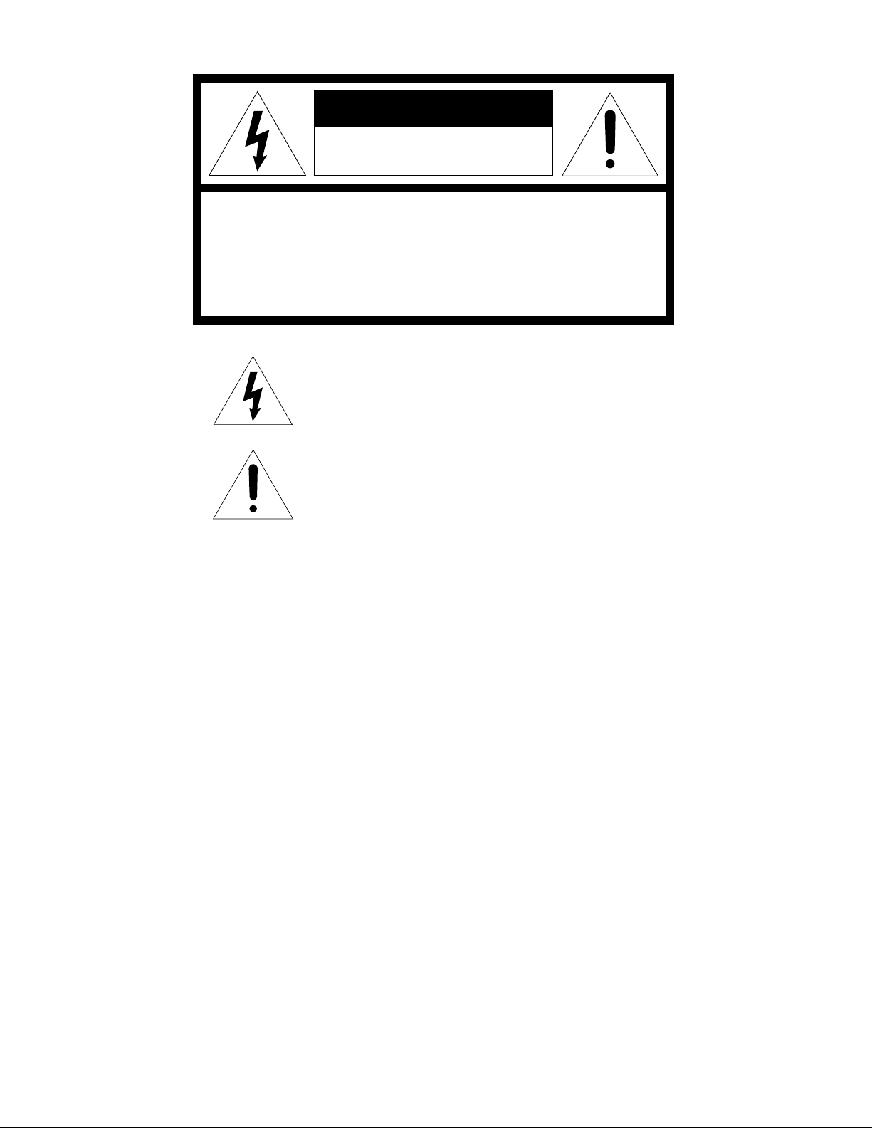
CAUTION
RISK OF ELECTRIC SHOCK
DO NOT OPEN
CAUTION: TO REDUCE THE RISK OF ELECTRIC SHOCK,
DO NOT REMOVE COVER (OR BACK)
NO USER-SERVICEABLE PARTS INSIDE
REFER SERVICING TO QUALIFIED SERVICE PERSONNEL
The lightning flash with arrowhead symbol, within
an equilateral triangle, is intended to alert the user
to the presence of uninsulated "dangerous voltage"
within the product's enclosure that may be of sufficient magnitude to constitute a risk of electric shock
to persons.
The exclamation point within an equilateral triangle
is intended to alert the user to the presence of
important operating and maintenance (servicing)
instructions in the literature accompanying the appliance.
WARNING
TO REDUCE THE RISK OF FIRE OR ELECTRIC SHOCK,
DO NOT EXPOSE THIS APPLIANCE TO RAIN OR MOISTURE.
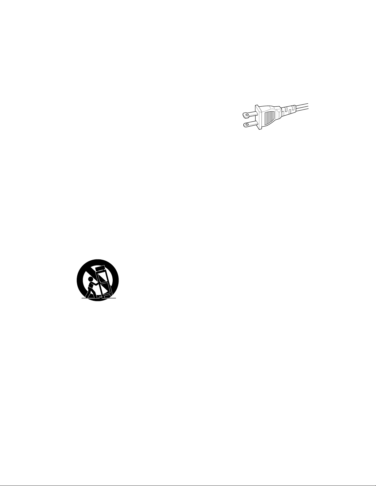
CAUTION: TO PREVENT ELECTRIC SHOCK, MATCH WIDE
BLADE OF PLUG TO WIDE SLOT, FULLY INSERT.
ATTENTION: POUR ÉVITER LES CHOCS ÉLECTRIQUES,
INTRODUIRE LA LAME LA PLUS LARGE DE LA
FICHE DANS LA BORNE CORRESPONDANTE DE LA
PRISE ET POUSSER JUSQU'AU FOND.
LASER SAFETY
This unit employs a laser, Only a qualified service person should remove
the cover or attempt to service this device, due to possible eye injury.
"CAUTION - USE OF CONTROLS OR ADJUSTMENTS
OR PERFORMANCE OF PROCEDURE
OTHER THAN THOSE SPECIFIED HEREIN
MAY RESULT IN HAZARDOUS RADIATION EXPOSURE.
1
Page 3
SAFETY
INSTRUCTIONS
READ BEFORE OPERATING EQUIPMENT
This product was designed and manufactured to meet strict quality
and safety standards. There are, however, some installation and
operation precautions which you should be particularly aware of.
1. Read Instructions — All the safety and operating instructions
should be read before the appliance is operated.
2. Retain Instructions — The safety and operating instructions
should be retained for future reference.
3. Heed Warnings — All warnings on the appliance and in the
operating instructions should be adhered to.
4. Follow Instructions — All operating and use instructions should
be followed.
5. Water and Moisture — The appliance should not be used near
water-for example, near a bathtub, wash-bowl, kitchen sink,
laundry tub, in a wet basement, or near a swimming pool, etc.
12. Grounding or Polarization — Precautions should be taken so that
the grounding or polarization means of an appliance is not
defeated.
AC POLARIZED PLUG
13. Power-Cord Protection — Power-supply cords should be routed
so that they are not likely to be walked on or pinched by items
placed upon or against them, paying particular attention to cords
at plugs, convenience receptacles, and the point where they
exit from the appliance.
14. Cleaning — The appliance should be cleaned only as recommended by the manufacturer.
6. Carts and Stands — The appliance should be used only with a
cart or stand that is recommended by the manufacturer.
7. An appliance and cart combination should be moved with care.
Quick stops, excessive force, and uneven surfaces may cause
the appliance and cart combination to overturn.
8. Wall or Ceiling Mounting — The appliance should be mounted
to a wall or ceiling only as recommended by the manufacturer.
9. Ventilation — The appliance should be situated so that its
location or position does not interfere with its proper ventilation.
For example, the appliance should not be situated on a bed,
sofa, rug, or similar surface that may block the ventilation
openings; or, placed in a built-in installation, such as a bookcase
or cabinet that may impede the flow of air through the ventilation
openings.
10. Heat — The appliance should be situated away from heat
sources such as radiators, heat registers, stoves, or other
appliances (including amplifiers) that produce heat.
11. Power Sources — The appliance should be connected to a
power supply only of the type described in the operating
instructions or as marked on the appliance.
15. Power Lines — An outdoor antenna should be located away
from power lines.
16. Outdoor Antenna Grounding — If an outside antenna is connected to the receiver, be sure the antenna system is grounded
so as to provide some protection against voltage surges and
built up static charges.
Section 810 of the National Electrical Code, ANSI/NFPA No. 70
— 1984, provides information with respect to proper grounding
of the mast and supporting structure, grounding of the lead-in
wire to an antenna discharge unit, size of grounding conductors,
location of antenna-discharge unit, connection to grounding
electrodes, and requirements for the grounding electrode. See
Fig. 1.
17. Nonuse Periods — The power cord of the appliance should be
unplugged from the outlet when left unused for a long period of
time.
18. Object and Liquid Entry — Care should be taken so that objects
do not fall and liquids are not spilled into the enclosure through
openings.
19. Damage Requiring Service — The appliance should be serviced
by qualified service personnel when:
A. The power-supply cord or the plug has been damaged; or
B. Objects have fallen, or liquid has spilled into the appliance;
or
C. The appliance has been exposed to rain; or
D. The appliance does not appear to operate normally or
exhibits a marked change in performance; or
E. The appliance has been dropped, or the enclosure dam-
aged.
20. Servicing — The user should not attempt to service the appliance beyond that described in the operating instructions. All
other servicing should be referred to qualified service personnel.
2
Page 4
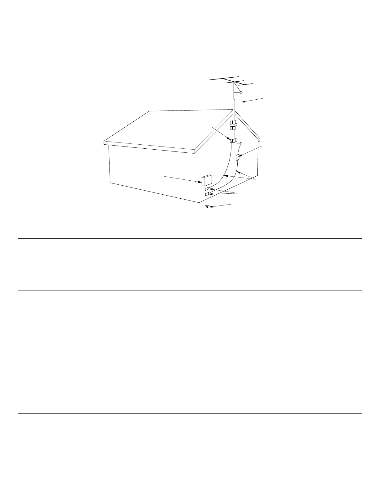
FIGURE 1
EXAMPLE OF ANTENNA GROUNDING ACCORDING TO
NATIONAL ELECTRICAL CODE INSTRUCYIONS
CONTAINED IN ARTICLE 810 -"RADIO AND TELEVISION EQUIPMENT"
ANTENNA LEAD
IN WIRE
GROUND CLAMP
ANTENNA
DISCHARGE UNIT
(NEC SECTION 810-20)
ELECTRIC
SERVICE
EQUIPMENT
POWER SERVICE GROUNDING
ELECTRODE SYSTEM
(NEC ART 250, PART H)
GROUNDING CONDUCTORS
(NEC SECTION 810-21)
GROUND CLAMPS
NEC - NATIONAL ELECTRICAL CODE
NOTE TO CATV SYSTEM INSTALLER:
This reminder is provided to call the CATV (Cable-TV) system installer's attention to Article 820-40 of the NEC, which
provides guidelines for proper grounding and, in particular, specifies that the cable ground shall be connected to the
grounding system of the building, as close to the point of cable entry as practical.
NOTE:
This equipment has been tested and found to comply with
the limits for a Class B digital device, pursuant to Part 15
of the FCC Rules. These limits are designed to provide
reasonable protection against harmful interference in a
residential installation. This equipment generates, uses
and can radiate radio frequency energy and, if not installed and used in accordance with the instructions, may
cause harmful interference to radio communications.
However, there is no guarantee that interference will not
occur in a particular installation. If this equipment does
cause harmful interference to radio or television reception, which can be determined by turning the equipment
off and on, the user is encouraged to try to correct the
interference by one or more of the following measures:
– Reorient or relocate the receiving antenna.
– Increase the separation between the equipment and
receiver.
– Connect the equipment into an outlet on a circuit
different from that to which the receiver is connected.
– Consult the dealer or an experienced radio/TV techni-
cian for help.
NOTE:Changes or modifications may cause this unit to
fail to comply with part 15 of the FCC Rules and may void
the user′s authority to operate the equipment.
This Class B digital apparatus meets all requirements
of the Canadian Interference-Causing Equipment
Regulations.
Cet appareil numérique de la Classe B respecte toutes
les exigences du Règlement sur le matérier brouilleur
du Canada.
3
Page 5
Page 6

ENGLISH
INTRODUCTION ................................................................................................................................................ 6
PRECAUTIONS .................................................................................................................................................. 6
FEATURES .........................................................................................................................................................6
REAR PANEL CONNECTIONS ..........................................................................................................................7
FRONT PANEL FEATURES ...............................................................................................................................7
DISPLAY INDICATORS...................................................................................................................................... 9
OPERATIONS.....................................................................................................................................................9
CASSETTE DECK OPERATION .........................................................................................................................9
CASSETTE TAPE REWIND/FAST FORWARD..................................................................................................9
CASSETTE TAPE RECORD................................................................................................................................9
COMPACT DISC PLAYER OPERATION ..........................................................................................................10
PROGRAMMING PLAYBACK TRACKS (PROGRAM PLAY MODE) ..............................................................10
CD TO TAPE DUBBING ................................................................................................................................... 10
MANUAL LEVEL TAPE DUBBING ..................................................................................................................10
AUTOMATIC RECORD LEVEL TAPE DUBBING ............................................................................................11
EXTENDED CASCADE OPERATION...............................................................................................................11
EXTENDED CASCADE PLAYBACK................................................................................................................. 11
EXTENDED CASCADE RECORDING ..............................................................................................................11
SYNCHRONIZED RECORDING CONTROL.....................................................................................................12
REMARKS ........................................................................................................................................................12
CARE AND MAINTENANCE............................................................................................................................12
REPAIRS ...........................................................................................................................................................12
TROUBLESHOOTING ......................................................................................................................................13
TAPE DECK ......................................................................................................................................................13
CD PLAYER ......................................................................................................................................................13
CLEANING OF EXTERIOR SURFACES...........................................................................................................14
COMPACT DISCS ............................................................................................................................................14
CONTENTS
GENERAL PRECAUTIONS ........................................................................................................................ 6
QUICK OPTICAL AUTOREVERSE.............................................................................................................6
TAPE AND CD PITCH CONTROL ..............................................................................................................6
RC-5 REMOTE CONTROL COMPATIBILITY .............................................................................................6
ONE TOUCH DUBBING.............................................................................................................................6
DUAL CD MEMO POINTS .........................................................................................................................6
LOCKABLE REM TRACK TIME MODE......................................................................................................6
ONE TRACK PLAY AND STOP MODE...................................................................................................... 6
AUDIO QUE CD PLAY ...............................................................................................................................6
DOLBY NR SYSTEMS ............................................................................................................................... 6
DOLBY HX PRO HEADROOM EXTENSION .............................................................................................6
TAPE DECK CONTROL BUTTONS ........................................................................................................... 7
CD PLAYER CONTROL BUTTONS ........................................................................................................... 7
CASSETTE TAPE PLAYBACK ...................................................................................................................9
COMPACT DISC PLAYBACK...................................................................................................................10
SELECTING THE TRACK FOR PLAYBACK .............................................................................................10
CAUTION..................................................................................................................................................12
ERASURE OF TAPE ................................................................................................................................. 12
AUTO TAPE SELECTOR .......................................................................................................................... 12
TO PROTECT VALUABLE RECORDINGS............................................................................................... 12
MAINTENANCE FOR TAPE.....................................................................................................................12
CLEANING OF EQUIPMENAL SURFACES............................................................................................12
5
Page 7

INTRODUCTION
Thank you for selecting the Marantz PMD350 combination Stereo Cassette
Deck/CD Player. Please read these operating instructions carefully. We
recommend that you read the entire user guide prior to connecting and
operating the unit. It is also recommended that all connections be made
prior to operating the unit.
Please refer to this manual to identify controls and connections
for operation of the unit.
PRECAUTIONS
The following precautions should be taken when operating the equipment.
GENERAL PRECAUTIONS
When setting the equipment ensure that:
- Air is allowed to circulate freely around the equipment.
- The equipment is on a vibration free surface.
- The equipment will not be exposed to interference from an external
source.
- The equipment will not be exposed to excessive heat , cold, moisture
or dust.
- The equipment will not be exposed to direct sunlight.
• In addition, never place heavy objects on the equipment.
• Never place heavy objects on the equipment.
• Should the unit become exposed to moisture do not operate the unit
until it has been thoroughly inspected by a electrically competent
technician.
• Do not break the connection to the AC main power by pulling the power
cord. Remove from the outlet by pulling on the plug only.
FEATURES
QUICK OPTICAL AUTOREVERSE
In addition to the normal tension reversing circuitry the PMD350 tape
transport also employs optically sensed quick autoreverse circuitry. This
circuitry reacts to the clear areas of the tape, usually the leader tape, and,
when detected will reverse the
direction of the tape transport. This process minimizes the lose of signal
being recorded or played back. This reverse process applies to all tape
playback and recording modes , including autoreverse and continuous
mode.
TAPE AND CD PITCH CONTROL
The PMD350 tape player and CD player both allow for adjustment of the
playback pitch from -12% to +12%.The feature is particularly usefully for
adjusting the unit playback pitch to allow you to tune the PMD350 to
accompanying instruments and choirs.
RC-5 REMOTE CONTROL COMPATIBILITY
The PMD350 comes equipped with an RC-5 remote in and out port.
Through the use of various remote control options
Marantz has available the major functions of the unit can be operated via
wired or wireless remote control.
ONE TOUCH DUBBING
The PMD350 allows for the dubbing of the CD to the tape with one button
start control. This feature allows you to manually or automatically select the
recording level you desire.
DUAL CD MEMO POINTS
The PMD350 allows you to select two points within the CD playback mode
and repeat the audio playback within these points until a stop command is
issued.
LOCKABLE REM TRACK TIME MODE
The CD time display can be toggled between the various modes of display.
In addition to this, when a display mode is set the unit will remain in the
selected mode until you change it.
This is particularly useful for DJ’s monitoring the audio during performances
and programs.
ONE TRACK PLAY AND STOP MODE
The PMD350 can be set to allow for the CD player to play the selected track
and return to the stop mode rather than continue on to the next track on the
CD.
AUDIO QUE CD PLAY
The CD player on the PMD350 contains the Audio Que feature. This feature
allows the CD player to advance to the beginning of the audio within the
track rather than start from the track start
flag. This feature helps to minimize the silence at the beginning of a CD track
playback.
DOLBY NR SYSTEMS
The Dolby Noise Reduction systems compress and amplify the tape during
recording in order to raise the signal-to-noise ratio on the tape. During
playback, these signals are expanded and
attenuated by the same amount in order to regain the original dynamic
range of music. An additional result of this expansion and attenuation is that
the noise floor of the recording is reduced significantly. Dolby B typically
reduces noise by 10dB.
Dolby C typically reduces noise by 20 dB.
DOLBY HX PRO HEADROOM EXTENSION
The Dolby HX PRO system monitors the total amount of effective bias
during recording and instantaneously compensates for any excess bias by
reducing the deck’s bias signal level accordingly. The system operates
independently on
each channel. HX Pro is unlike a noise reduction system because it
functions only during recording and no decoding is required. Therefore a
tape recorded with the HX Pro system
can be played back on any other cassette deck while retaining the benefits
of HX Pro.
6
Page 8

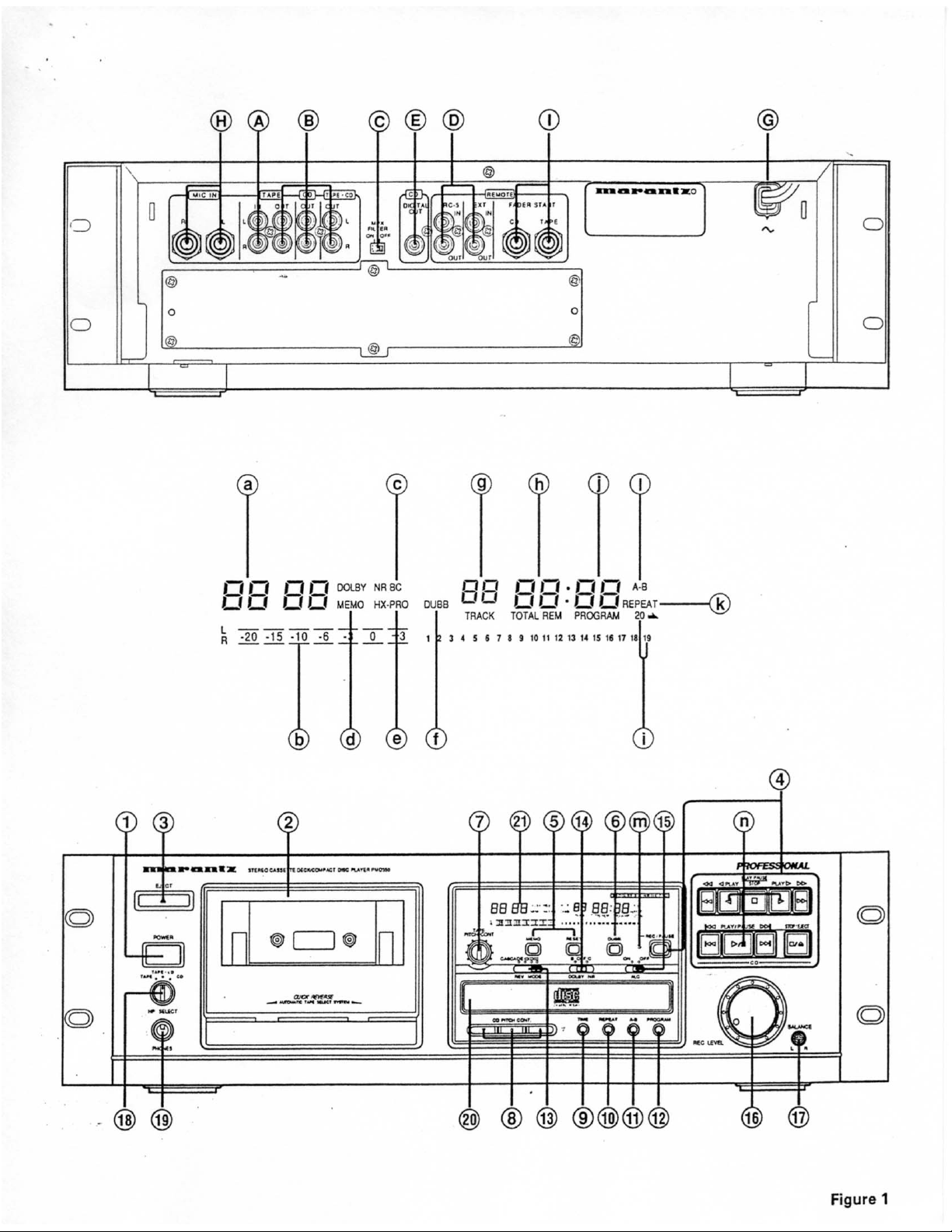
REAR PANEL CONNECTIONS
A LINE INPUT
These jacks should be connected to the LINE OUTPUT of your
source.
B LINE OUTPUT(Tape,CD,Mix)
These jacks should be connected to the appropriate INPUT of
your PA or monitoring system.
C MPX FILTER SWITCH
When recording FM broadcast with Dolby NR, set this switch
to the ON position.
D RC-5 REMOTE CONTROL JACKS
These jacks are used with the Marantz infrared or wired
remote accessories to provide remote control operation of
the PMD350. These jacks can be serially linked to provide
serial remote control operation of multiple RC-5 equipped
products as well.
E DIGITAL OUTPUT JACKS(IEC958 type II)
This connector outputs the digital signal of the CD Player.
Connect this jack to other IEC958 type II digital inputs such as
a D/A Converter, digital sound processor or amplifier with
IEC958 type II digital inputs such as the Marantz Compact Disc
Recorder.
F REMOTE EXT(extension) JACKS
Connection with other Marantz components equipped with
the REMOTE EXT. jacks will allow for extended cascade
operation of several units.
G POWER CORD
120VAC input power connector.
H MIC(MICROPHONE) INPUT JACKS
For use with microphones as the input source into the tape
deck. When microphones are installed into these jacks, the
line inputs are automatically switched off and only the microphone signal is input into the unit. For mono recording insert
the microphone into the L (Left) jack .
I FADER START JACKS
Upon receiving a dry switch contact closure on the jack
connections, the CD Player can be switched in and out of play
and play/pause mode. The Tape deck can be switched in and
out of play and stop or the record and stop mode.
FRONT PANEL FEATURES
q POWER SWITCH BUTTON
Push the POWER switch in to turn power to the unit on and
off. When power is turned off, all past setting are removed
from memory and the unit returns to its default setting upon
the next power up.
w CASSETTE TAPE HOLDER
This section holds the cassette tape for tape Play and Record functionality. Tapes that have the record protect knockout removed will not enter into the record mode.
e EJECT BUTTON
Press the eject button to open the cassette tape holder.
r TAPE DECK AND CD PLAYER CONTROL
TAPE DECK CONTROL BUTTONS
: STOP BUTTON
Press the stop button to cancel all current operations of the
tape deck.
: FORWARD PLAY BUTTON
Press the forward play button to engage the tape deck into the
forward play function.
: REVERSE PLAY BUTTON
Press the reverse play button to engage the tape deck into the
reverse play function.
: REWIND BUTTON
Press the rewind button to engage the tape transport into fast
rewind mode from the right(take-up) to the left(supply) reels.
: FAST FORWARD BUTTON
Press the fast forward button to engage the tape transport into
the fast forward wind mode from the left(supply) to the
right(take-up) reels.
: REC/PAUSE BUTTON
Press the rec / pause button to engage the tape transport into
the record pause mode. In this mode the tape deck is armed
to begin recording. The tape record mode can be engaged by
pressing the forward play
CD PLAYER CONTROL BUTTONS
or reverse play buttons.
STOP/EJECT BUTTON
Press the Stop/Eject button to stop the CD Player while in the
play mode. Press the Stop/ Eject button while in the Stop
mode to open the door and eject the disk. During the program
mode the Stop/Eject button will cancel the current program as
long as the CD player is in the Stop mode.
PLAY/PAUSE BUTTON
Press the PLAY/PAUSE button the change the CD player
mode from CD play to CD pause or from CD pause to CD play.
PREVIOUS BUTTON
When the CD player is in the play or pause mode, pressing the
PREVIOUS button will skip back one track for every time the
button is pushed.
During the program mode this function is used along with the
next button to select the desired tracks to be played.
Press and hold during playback to fast reverse the CD play.
NEXT BUTTON
When the CD player is in the play or pause mode, pressing the
NEXT button will skip forward one track for every time the
button is pushed. During the program mode this function is
used along with the previous button to select the desired
tracks to be played.
Press and hold during playback to fast forward the CD play.
t TAPE COUNTER BUTTON
MEMO BUTTON
Press the MEMO button to store a memory point into the
counter memory. Once this point is set, the tape deck will
rewind or fast forward until it reaches this point in the tape and
will stop. To cancel the memory control press the MEMO
button again.
RESET BUTTON
Press the RESET button to reset the current tape counter
reading from its existing point to “0000”.
7
Page 9

6 DUBB BUTTON
Press the DUBB button to engage the tape transport into the
dubbing mode from the CD player. Once the DUBB button is
pressed, the CD player will copy directly to the tape deck.
7 TAPE PITCH BUTTON
Rotate the tape deck pitch control to adjust the tape deck
playback pitch from -12% to +12%.
While the control is in the center detent position, the tape deck
is at normal(0% pitch variance) speed. This control has no
effect on the tape pitch during the record mode.
8 CD PITCH CONTROL BUTTON
By pressing the CD player pitch control buttons you can
adjust the CD player playback pitch from -12% to +12% in .1%
increments. You can return the CD player to the normal speed
position by pressing the center “0” control.
Holding the pitch + or - controls for 2 or more seconds will
cause the pitch to adjust in .5% increments.
CAUTION: When the CD pitch control is used, digital lock
may not occur with some D/A converters.
9 TIME BUTTON
By pressing the TIME button you can adjust the CD player time
displayed from the following formats. NORMAL- Displays the
time elapsed within the current track being played. REMDisplays the remaining time left of the current track being
played. TOTAL REM- Displays the total time remaining on the
current disk being played. This control can be toggled between the various displays by pressing the TIME button
multiple times.
0 REPEAT BUTTON
By pressing the REPEAT button you can program the CD
player to repeat all tracks of the current disk. When there is a
CD play program that is currently active, this function will
repeat the current program selections. To clear this function,
press the repeat control button again.
q A-B BUTTON
The A-B BUTTON allows you to repeat a specific section in
the current CD track that is being played. When this control is
pressed the first time, the A-B indicator flashes and this
position on the track is noted as the start or A point.
When this control is pressed again, the A-B indicator lights
continuously, and this position on the track is noted as the end
or B point. After setting the end point the CD player returns to
the start point (A), and plays until it reaches the end point (B).
The CD player will repeat this function until the stop or A-B
button is press again.
w PROGRAM BUTTON
The PROGRAM button will place the CD player into the
program entry mode or the single track play mode. When the
PROGRAM button is pressed once, the CD player enters the
program entry mode and the program indicator will begin to
flash. Pressing the PROGRAM button again will place the CD
player in the single track play mode, and the track indicator will
begin to flash. Pressing the PROGRAM button again will
return the CD player to the normal play mode.
e REVERSE MODE SWITCH
The Reverse Mode switch allows you to set the automatic
tape direction operation of the tape transport during playback,
normal recording or dubbing. The 4 positions of this switch are
as follows;
: One-way mode.
In this position the tape will play or record one side of the
tape and stop.
: Two-way mode.
In this position the tape will play or record both sides of the
tape and stop.
: Continuous mode
In this position the tape will play the tape in a continuous
loop until the stop command is given. In the record mode
the tape will record both sides of the tape and stop.
CASCADE MODE:
In this position multiple Marantz tape decks that are equipped
with the “EXT” cascade connector can be looped together
to allow for extended cascade playback or recording. In this
mode the tape will play or record both sides of the tape and
at the end of the tape on the first deck a command will be
issued causing the next deck in line to begin cascade play
or record. This will continue until the end of the last tape on
the last deck of the loop is reached.
r DOLBY NOISE REDUCTION SWITCH
The Dolby Noise Reduction switch allows for the encoding or
decoding of Dolby B or C Noise Reduction. When recording
with Dolby Noise Reduction on, select the type(B or C) of noise
reduction desired and place the switch in the appropriate
position. When playing a tape with Dolby Noise Reduction
encoded onto it, place this switch in the same position(B or C)
as it was record in.
t AUTOMATIC RECORD LEVEL SWITCH (ALC)
The ALC switch allows for automatic control of the source
level during recording. When this switch is set to the OFF
position, the level of recording is controlled by the manual
record level adjustment. When this control is set to the ON
position, the record level is set automatically. In this position
the manual record level adjustment has no effect on the
recording.
y MANUAL RECORD LEVEL CONTROL
The manual record level control allows you to adjust the record
level up or down during recording.
u RECORD BALANCE RECORD
The recessed balance control allows for the adjustment of the
record level between the left and right channels. By using a
phillips type screwdriver, you can adjust this balance control
between Left(Counter-clockwise) and Right(Clockwise).
i HEADPHONE SLECTOR SWITCH
Used to switch the headphone output.
o HEAPHONES JACK
The headphones jack is used to allow monitoring of the Tape,
CD or Tape/CD Mix through headphones. This jack requires
that a 1/4" headphone jack connection be made and the
desired source can be selected by the HP SELECT switch
located diectly above theheadphone input jack.
p COMPACT DISC TRAY
The Compact Disc tray is used to hold the desired CD for
8
playback.
Page 10

DISPLAY INDICATORS
Tape counter display indicates the amount of tape that has
been transported across the head in digits.
Level indicators display the record or playback signal levels of
the tape deck.
Dolby NR B C indicators display the type of Dolby noise
reduction that has been selected.
¶ MEMO indicator is Displayed when the tape deck memory
function is turned on.
« HX PRO indicator is displayed showing HX PRO is activated.
˜ DUBB indicator is displayed when dubbing from the CD player
to the tape deck.
' TRACK number indicator displays the track number that the
CD has identified in play or pause mode. In the stop mode, the
number of tracks on the entire CD or the numbers of the tracks
programmed to play are displayed. When the TRACK number
indicator is flashing it indicates that the CD player is in the
single track play mode. When in this mode the CD player will
play the selected track and go to the stop mode.
œ TRACK time indicator displays the playing time of the CD in 4
digits representing minutes and seconds. This display typically represents elapsed time of the track being played. When
the REM indicator is displayed, the time shown represents the
remaining time of the track being played. When the TOTAL REM indicator is displayed, this represents the total
remaining time of the CD or of the program currently being
played. In the stop mode the total playing time of the CD is
displayed. The flashing colon, “ : “ indicates that the CD pitch
control is in use.
Ò TRACK number indicator(1 through 20), displays the track
numbers on the CD. When in the program mode the tracks
programmed are displayed . Upon completion of playing
a track, the number will disappear. When playing a CD with
more than 20 tracks on it, the “=>” indicator is displayed.
D PROGRAM indicator is displayed to indicate that the CD player
is in the program mode. The indicator flashes during the
program play entry mode. This indicator can be turned on and
off by pressing the program button.
ß REPEAT indicator is displayed when the CD player is in the
repeat mode.
´ A-B indicator is displayed when the tape deck is in the A-B
repeat mode. When the A-B indicator is flashing, this indicates
standby for the setting of point B.
m REC indicator is displayed when the tape deck is in the Record
mode. When the REC indicator is flashing, this indicates the
tape deck is in the Record Pause mode.
£ TAPE DECK PLAY indicator(located inside of the tape play
button) displays the direction and mode of the tape transport,
Play or Pause.When the indicator is flashing this indicates the
transport is in the pause mode and the direction thetransport is assigned. When the indicator is constantly on, this
indicates that the transport is in the play or record mode and
the direction that the transport is assigned. This indicator
will not light if there is not a tape in the transport.
CD PLAYER PLAY indicator(located inside of the CD play
button) displays a constant indicator when the CD Player is in
the Play mode and a flashing indicator when the CD Player is
in the Pause mode.
Operations
The following operating procedures are based on the assumption
that the power switch is set to the ON position and that all input
and output connections have already been made. For examples of
input and output connections, please refer to the section in this
manual marked “Connections”.
CASSETTE DECK OPERATION
CASSETTE TAPE PLAYBACK
1. Open the cassette holder by pressing the eject button. Load a
cassette tape into the cassette holder and close. The 5 indicator
on the play control button will begin to flash.
2. Set the Dolby Noise Reduction control switch to the same
position as the tape was originally recorded in(i.e. tapes recorded with Dolby B noise reduction need to have this switch
in the Dolby B position, tapes recorded with Dolby C noise
reduction need to have this switch in the Dolby C position, and
tapes recorded without Dolby Noise Reduction need to have
this control set to the Off position).
3. Set the reverse mode control switch to the desired position.
4. Press the 5 play control button to begin playback in the forward
direction. Press the 4 play control button to begin playback in the
reverse play direction. When the tape enters into the playback
mode the indicator on the play control button will change from
the flashing mode to a constant on mode to indicate playback is
operating.
5. Pressing the stop control button will stop the tape transport
during playback.
CASSETTE TAPE REWIND/FAST
FORW ARD
Regardless of the direction that the tape transport is currently in,
pressing the 2 (Fast Forward) control button will place the tape
transport in the high speed fast forward mode and the tape will
advance quickly from left to right. Pressing the 1 (Rewind) control
button will place the tape transport in the high speed rewind mode
and the tape will retract quickly from right to left.
In either the fast forward or the rewind mode, the tape transport will continue to fast forward or re win d un til the stop control
button is pressed or the end of the tape is reached.
CASSETTE T APE RECORD
1. Open the cassette holder by pressing the eject button. Load a
recordable cassette tape into the cassette holder and close. The
5 indicator on the play control button will begin to
flash. (If you wish to change the tape direction, press the 4 play
control button and then press the stop control button).
2. Set the Dolby Noise Reduction control switch to the position
that you want to record the tapes noise reduction in(i.e. tapes to
be recorded with Dolby B noise reduction need to have this
switch in the Dolby B position, tapes to be recorded with Dolby
C noise reduction need to have this switch in the Dolby C
position, and tapes to be recorded without Dolby Noise Reduction need to have this control set to the Off position). When
recording FM broadcast with Dolby Noise reduction on, set the
MPX switch to the On position.
3. Set the reverse mode control switch to the desired position.
4. Set the ALC control mode switch to the ndesired position, on or
off.
9
Page 11

5. Press the rec/pause control button. The REC indicator will begin
to flash indicating the tape transport is in the record pause
mode.
6. If the ALC control button is in the Off position, using the manual
record level control adjust the input signal to the desired
recording level.
7. Press the 5 play control button to begin recording in the forward
direction. Press the 4 play control button to begin recording in the
reverse direction. When the tape enters into the playback mode
the REC indicator and the play control button indicator will
change from the flashing mode to the constant on mode.
Thisindicates the tape transport is in the record mode.
8. To pause the tape transport during recording press the rec/
pause control button. Press the play control button to resume
recording.
9. Pressing the stop control button will stop the tape transport
during recording. Pressing the 1 rewind in the 5 play/record
direction or the
2 FAST FORWARD in the 4 play/record direction will cause the
unit to return to the position the recording began at.
COMPACT DISC PLAYER OPERATION
COMPACT DISC PLAYBACK
1. Open the compact disc tray by pressing the STOP/EJECT
button. Load a compact disc onto the compact disc tray and
close the tray by gently pushing the front of the compact disc
tray or by pressing the STOP/EJECT button. The CD player
display will show the general data of the current CD.
2. To begin playback of the compact disc press the CD play/pause
control button. The 5 indicator in the CD PLAY/PAUSE button
will illuminate, the display will show the data for the first track
and the track will begin to play.
3. To pause the CD during playback, press the CD PLAY/PAUSE
button. The display will remain in the current position and the
5 indicator in the CD PLAY/PAUSE button will begin to flash.
Pressing the CD PLAY/PAUSE button will resume normal
playback from the point that the CD player was paused.
4. Upon completion of playback of the last track in the disc the CD
Player will return to the stop mode. You can also stop the CD
playback by pressing the STOP/EJECT button once.
Pressing the STOP/EJECT button again will cause the CD tray
to open.
SELECTING THE TRACK FOR PLAYBACK
1. By pressing the CD 7 NEXT or the CD 6 PREVIOUS buttons you
can select the track to be played. Each press of the CD 7 button
will advance the CD player to the beginning of the next track and
enter into the play pause mode.
Each press of the CD 6 button will cause the CD player to skip
to the beginning of the previous track and enter into the play
pause mode. Pressing the CD PLAY/PAUSE button will resume
playback at the beginning of the selected track.
PROGRAMMING PLAYBACK TRACKS
(PROGRAM PLAY MODE)
This procedure allows you to program selected tracks for playback
in the order you desire.
1. By pressing the PROGRAM button once you will place the CD
player into the programming mode for playback. Once the
PROGRAM button is pressed the PROGRAM indicator in the
CD display will begin to flash. This indicates the CD player is in
the program entry mode.
2. By pressing the CD 7 NEXT or the CD 6 PREVIOUS buttons you
can select the track to be programmed. Each press of the CD 7
button will advance the CD player to the beginning of the next
track. Each press of the CD 6 button will cause the CD player to
skip to the beginning of the previous track. When the
desired track number has been selected, leave the CD player
untouched for approximately 1.5 seconds and the selected
track will be stored in the playback program. Continue this
procedure until all desired tracks(20 tracks maximum) have
been programmed.
3. By pressing the PLAY/PAUSE button the CD player will exit the
program entry mode and enter the program play mode. The
PROGRAM indicator in the CD display will go to constant on and
the CD player will begin to play in the order selected during the
programming.
4. By pressing the STOP/EJECT button the CD player will stop
playing but will remain in the program play mode. The program
will remain in memory.
5. When the STOP/EJECT button is pressed while the CD player
is in the stop mode and while the program is still engaged, the
memorized program will be cleared.
CD TO TAPE DUBBING
The CD source can be dubbed directly on to the tape deck by two
means, manual recording or automatic level control(ALC On).
During manual record dubbing the level desired is adjusted by
manually adjusting the record level control. After the desired level
is adjusted, you then release the tape deck to record. During ALC
dubbing the record level is adjusted automatically based on the
peak levels of the source and the tape deck enters the dubbing
mode automatically.
MANUAL LEVEL TAPE DUBBING
1. By pressing the CD STOP/EJECT button and the tape eject
button you can load the CD to be dubbed onto the CD tray and
a recordable tape into the tape transport. Gently press the front
of each of the mechanism to close them. The CD display will
register the general CD data and the tape play indicator located
inside of the tape PLAY button will begin to flash.
2. Prepare the tape for dubbing by rewinding it to the beginning of
the first side that the tape is to be recorded onto.
3. Set the ALC switch to the OFF position.
4. Press the DUBB button once. The REC indicator will begin to
flash, the DUBB indicator will light and the CD player will enter
play mode. At this point you can adjust the record level control
to achieve the desired record level.
5. After adjusting the record level, press the DUBB button again.
The CD player will return to the stop mode, and the tape
transport will enter into the record mode. After approximately 5
seconds the CD player will enter the playback mode and begin
to play the first track, dubbing it onto the tape.
6. When either the CD transport or the tape transport have
reached the end and stopped, the other transport will also stop.
7. To end the dubbing during a session, press the STOP on the
tape transport or the STOP/EJECT button on the CD player.
10
Page 12

AUTOMATIC RECORD LEVEL TAPE
DUBBING
1. By pressing the CD STOP/EJECT button and the tape eject
button you can load the CD to be dubbed onto the CD tray and
a recordable tape into the tape transport. Gently press the front
of each of the mechanism to close them. The CD display will
register the general CD data and the tape play indicator located
inside of the Tape PLAY button will begin to flash.
2. Prepare the tape for dubbing by rewinding it to the beginning of
the first side that the tape is to be recorded onto.
3. Set the ALC switch to the ON position.
4. Press the DUBB button once. The REC indicator will begin to
flash, the DUBB indicator will light and the CD player will enter
play mode. The CD will automatically begin to search the
source for the peak level. This procedure could take as long as
5 minutes tocomplete. Once the peak level has been determined, the record level for dubbing will be set automatically.
5. After the record level has been set, the tape transport will enter
into the record mode. After approximately 5 seconds the CD
player will enter the playback mode and begin to play the first
track, dubbing it onto the tape.
6. When either the CD transport or the tape transport have
reached the end and stopped, the other transport will also stop.
7. To end the dubbing during a session, press the STOP on the
tape transport or the STOP/EJECT button on the CD player.
Notes:
When dubbing is started with a program of CD tracks, the
tracks are dubbed in the order that the original playback
was programmed for. For assistance in programming playback, see the section marked “Program Playback”.
During dubbing, a blank space of approximately 4 seconds is
automatically inserted between CD tracks. This may hinder some
dubbing such as live recordings on CD.
The CD peak level that is detected during ALC level dubbing may
vary from one recording to another, however the effect will be
minimal.
When recording with the reverse mode control set to the two way
or the continuous mode there may be an interruption in recording
of approximately 1 second during the optical reversing of the tape
transport.
EXTENDED CASCADE OPERATION
By using the cascade feature on the PMD350 with other PMD350’s
or other Marantz products offering the cascade feature, several
units can be connected to supply long playback or recording
functionality.
EXTENDED CASCADE PLAYBACK
1. Refer to the user guide of the other components to assure that
all connections and switch settings are set correctly.
2. Assure that the “EXT” jack on the rear of all units are connected.
Starting with the first unit to operate, connect the “EXT” out
jack to the “EXT input on the second unit to operate. Continue
this set-up procedure until all units that are to operate in the
cascade mode have the “EXT” control jacks serially linked
together.
3. Set the PMD350 reverse mode control switch to the cascade
position.
4. Begin the playback of the first source by pressing the play
control button. The unit will enter playback mode. After the first
source has completed playback, the next component in the
cascade will begin playback. This will continue until the last unit
linked in the cascade chain has completed playback and entered
the stop mode.
5. To exit out of the cascade playback mode, press the stop control
button of the source machine currently in playback mode.
EXTENDED CASCADE RECORDING
1. Refer to the user guide of the other components to assure that
all connections and switch settings are set correctly.
2. Assure that the “EXT” jack on the rear of all units are connected. Starting with the first unit to operate connect the
“EXT” out jack to the “EXT input on the second unit to operate.
Continue this set-up procedure until all units that are to operate
in the cascade mode have the “EXT” control jacks serially
linked together.
3. Set the PMD350 reverse mode control switch to the cascade
position.
4. Place all components that are linked together in the cascade
mode into the record pause mode.
5. Begin the recording of the first source by pressing the play
control button. The unit will enter record mode. After the first
source has completed recording, the next component in the
cascade will begin recording. This will continue until the last unit
linked in the cascade chain has completed recording and
entered the Stop mode.
6. To exit out of the cascade record mode, press the stop control
button of the source machine currently in record mode.
NOTES:
If all components have not be set up correctly, tape or CD
loaded, record pause armed, etc., the cascade function will
stop upon reaching this source machine.
If the cascade function is started with the tape first the PMD350
will go to CD playback next and then to the next component. If the
playback is started with the CD first the PMD350 will play the CD
then go to the next component.
Before beginning the cascade record function hand wind the tape
leaders so that no leader is showing. This will minimize interruptions in your recordings.
11
Page 13

SYNCHRONIZED RECORDING CONTROL
The PMD350 is capable of connecting with other Marantz RC-5
based products to allow for synchronized start of the product
recording through the starting of the play function of the CD player
or the tape transport of the PMD350.
By connecting the RC-5 output jack to the RC-5 input jack of
another Marantz recorder, the PMD350 will issue a command for
the recording to start as soon as the play control button is pressed
on the PMD350. Pressing the stop or the stop/eject control button
on the PMD source deck will place the attached component into
the record pause mode.
During the cascade recording mode, the PMD350 can be attached
to other Marantz RC-5 based decks for the purpose of small scale
duplication of the dubbing source. This is accomplished by linking
the RC-5 output connector to the RC-5 input of the recording deck
and placing the PMD350 reverse mode control switch into the
cascade position.
REMARKS
CAUTION
• If you must stop playback or recording in the middle of a tape,
be sure to press the STOP - button first, then turn the power off.
If the power is turned off in the middle of an operation, the
cassette tape remains loaded, and it may be impossible to eject.
In such a case, turn the power on, enter PLAY mode, then press
STOP, and the eject the tape.
• The same caution as above applies in case of power failure.
To prevent damage, never attempt to force the removal of a
cassette while the power is off.
ERASURE OF TAPE
When a program source is recorded onto a tape, the previously
recorded sound is erased automatically, and replaced with the new
recording. If you wish to erase a tape without recording, set the
REC LEVEL control to the minimum(0) position and let the tape
travel in the Record mode.
AUTO TAPE SELECTOR
This unit is equipped with an auto tape selector whitch automatically sets the bias and equalizer level using the detection holes
porovided in the cassette shell. The bias and equalizer levels are
automatically set according to the type of cassette as follows. (See
Figure 3)
• Normal tapes EQ; 120µS, Bias; Low
• HIGH/Position tapes EQ; 70µS, Bias; High
• Metal tapes EQ; 70µS, Bias; Metal
TO PROTECT VALUABLE RECORDINGS
In the record mode, information previously recorded on the tape
will automatically be erased. To prevent this from happening, use
a small screwdriver to break out one or both safety tabs (See Figure
4).
It is possible to restore the recording capability of either side of the
cassette by covering the opening with clear adhesive tape (See
Figure 5).
CARE AND MAINTENANCE
This section describes the care and maintenance tasks that must
be performed to optimize the operation of your Marantz equipment.
MAINTENANCE FOR TAPE
Head Cleaning
If the heads are not cleaned for a long period, dirt or dust may be
deposited on the heads and capstans, causing degraded highfrequency characteristics, volume drop, or degraded recording and
erasure performances.
To prevent this, clean the heads, etc., periodically as follows.
1. Turn the power off.
2. Open the cassette holder by pressing the EJECT button.
3. As shown in Figure 2, clean the parts which come in contact
with tape, including the heads, capstans, tape guides, pinch
wheels, etc., with a cotton swab soaked in head cleaning
solution.
Head Demagnetization
When a magnetized metallic objects (such as a screwdriver tip,
etc.) comes in contact with a head or capstan, or when the deck has
been used for a long period of time, the head may be magnetized
and noise may be generated. If the head is extremely magnetized,
the high frequencies in recorded tapes could even be erased.
To prevent this, demagnetize the heads and capstans periodically
(every 20 hours of use) using a commercially-available head demagnetizer. (For the operation, please refer to the instruction
manual supplied with your head demagnetizer.)
Caution: Be sure to turn the power of the cassette deck off
before using a head demagnetizer.
CLEANING OF EQUIPMENAL SURFACES
The exterior finish of your unit will last indefinitely with proper care
and cleaning. Never use scouring pads, steel wool, scouring
powders or harsh chemical agents (e.g., lye solution), alcohol,
thinners, benzine, insecticide or other volatile substances, as these
will mar the finish of the equipment. Likewise, never use cloths
containing chemical substances. If the equipment gets dirty, wipe
the external surfaces with a soft, lint -free cloth.
If the equipment becomes heavily soiled:
- dilute some liquid soap in water, in a ratio of one part detergent
to six parts water
- dip a soft, lint free cloth in the solution and wring the cloth out
until it is damp
- wipe the equipment with the damp cloth
- dry the equipment by wiping it with a dry cloth.
REPAIRS
Only the most competent and qualified technicians should be
allowed to service your unit. Marantz and its factory trained
warranty station personnel have the knowledge and special equipment needed for repair and calibration of this precision instrument.
In the event of difficulty, call the toll-free telephone number listed
on the face of the warranty to obtain the name address of the
Marantz Authorized Service Center nearest you. In many cases,
the dealer where you purchased your Marantz unit may be equipped
to provide service. Please include the model and serial number of
your unit together with a copy of your purchase receipt and a full
12
Page 14

description of what you feel is abnormal in its behavior.
TROUBLESHOOTING
Should faults occur it is in many cases not necessary to consult your
dealer or technical service department. On the basis of the following checks you will be able to rectify a number of conditions
yourself without difficulty.
If the condition cannot be remedied after the following check,
please consult your dealer or nearest Marantz service agent.
TAPE DECK
The tape does not travel.
1. Check that the power cord is plugged properly.
2. Check that the POWER switch is set to ON.
3. Check that the tape is rewound.
The tape travels, but no sound is output.
1. Check that the cassette tape is recorded.
2. Check that the mixer, amplifiers and speakers are connected and
functioning properly.
Tape will not record.
1. Check that the protection tabs of cassette tape are not broken.
2. Check that the recording level is set properly.
Sound is distored.
1. Check that the recording level is not too high.
2. Check that the head is not dirty.
Sound is unstable.
1. Check that the head is not dirty.
2. Check that the pinch wheels and capstans are not dirty.
3. Check that the tape is wound regularly.
Noise is noticeble.
1. Check that the head is not dirty.
2. Check that the head is not magnetized.
3. Check that the DOLBY NR switch is set properly according to
the tape.
Hum interferes with the sound.
1. Check that cords are connected properly.
2. Check that there is not any source of magnetism (TV, motor,
transformer, etc.) placed near the unit.
3. When this unit and amplifier are stacked, hum noise is sometimes generated depending on the amplifier model. In such a
case, place the components in positions where interference
does not occur.
correct input ("CD" or "AUX" whichever corresponds to the input
jacks the CD player is connected to).
The disc stops in mid-operation.
1. Check that the disc is not dirty.
2. Check that the disc is not scratched.
3. Check that the disc is not warped.
The sound drops out or noise is heard.
1. Check that the disc is not dirty.
CD PLA YER
The disc fails to rotate.
1. Check that the power cord is plugged in properly.
2. Check that the POWER switch is set to ON.
3. Check that the disc is placed in the correct position on disc tray.
4. Check that the disc is placed properly with the label side facing
up.
5. Check that the disc is not dirty.
6. Check that the disc is not scratched.
7. Check that the disc is not warped.
8. Check that the transport screws have been removed.
The disc is rotating but no sound is heard.
1. Check that the amplifier and speakers are connected properly.
2. Check that the amplifier is turned ON.
3. Check that the amplifier's volume control is not set at the
minimum level.
4. Check that the amplifier's input selector switch is set to the
13
Page 15

2. Check that the disc is not scratched.
3. Check that the disc is not warped.
CLEANING OF EXTERIOR SURF ACES
With proper care and cleaning, the exterior finish of your equipment will last indefinitely. Never use scouring pads, steel wool,
scouring powders or harsh chemical agents (e.g. lye solution),
alcohol, thinners,benzine, insecticide or other volatile substances,
as these will mar the finish of the cabinet. Likewise, never use
cloths containing chemical substances. If the equipment becomes
dirty, wipe the external surfaces with a soft, lint-free cloth.
If the cabinet becomes heavily soiled:
– dilute some washing-up liquid in water, in a ratio of one part
detergent to six parts water;
– dip a soft, lint-free cloth in the solution and wring the cloth out
until it is damp;
– wipe the equipment with the damp cloth;
– dry the equipment by wiping it with a dry cloth.
• Quick reverse operation will only occur after the transport has
been moving for 15 seconds. Before that time it take
approximatery 4 seconds to reverse.
• One second of audio is lost during quick reverse.
• Automatic search operations can only operate on one well at a
time.
• Eject buttons will not function unless the deck is in the stop
mode. Thus, if the power is turned off without hitting the STOP
button, the door may not open.
• The tape counters are only approximate measurements of min-
utes and seconds and are not intended for timing-critical applications. They are most accurate with 60 minute tapes.
NOTICE
capstans
heads
pinch wheels
Figure 2
COMPACT DISCS
The glossy side shining like a rainbow is the front side of the disc,
and the side on which the label is printed is the back.
Unlike conventional turntables for playing analog discs, Compact
Disc Player reads the information recorded on the disc from
underneath without contacting it using a beam of laser light.
Therefore, the performance of a compact disc will not degrade like
conventional analog records.
Handle discs carefully so as not to damage or scratch the front
side.
To protect the disc, avoid placing it in the following locations:
– In direct sunlight or near a source of heat like a heater.
– In a place which is damp or dirty.
– In a place which could be exposed to rain, such as near a
window.
Always keep the disc surface clean.
Up to six billion data units are recorded on the front side of the disc.
When cleaning the disc surface, always be sure to use a special
compact disc cleaner and wipe as shown below.
Figure 4
Metal tape
detection hole
HIGH/Position tape
detection hole
Figure 3
Wipe in a radial direction.
• Do not use conventional record cleaner for analog records, as
this will adversely affect the disc surface.
Store discs properly by placing them in their disc cases.
Do not wipe in circumferential direction.
Figure 5
14
Page 16

Dolby noise reduction and HX Pro headroom extension are manufactured under license from Dolby
Laboratories License Corporation. HX Pro was originated by Bang & Olufsen.
“DOLBY” the double D symbol and “HX PRO” are trademarks of Dolby Laboratories Licensing
Corporation.
is a registered trademark.
Printed in Japan 97/08 SK 474T851252
15
 Loading...