

Marantz PAC-750 Owners Manual
R
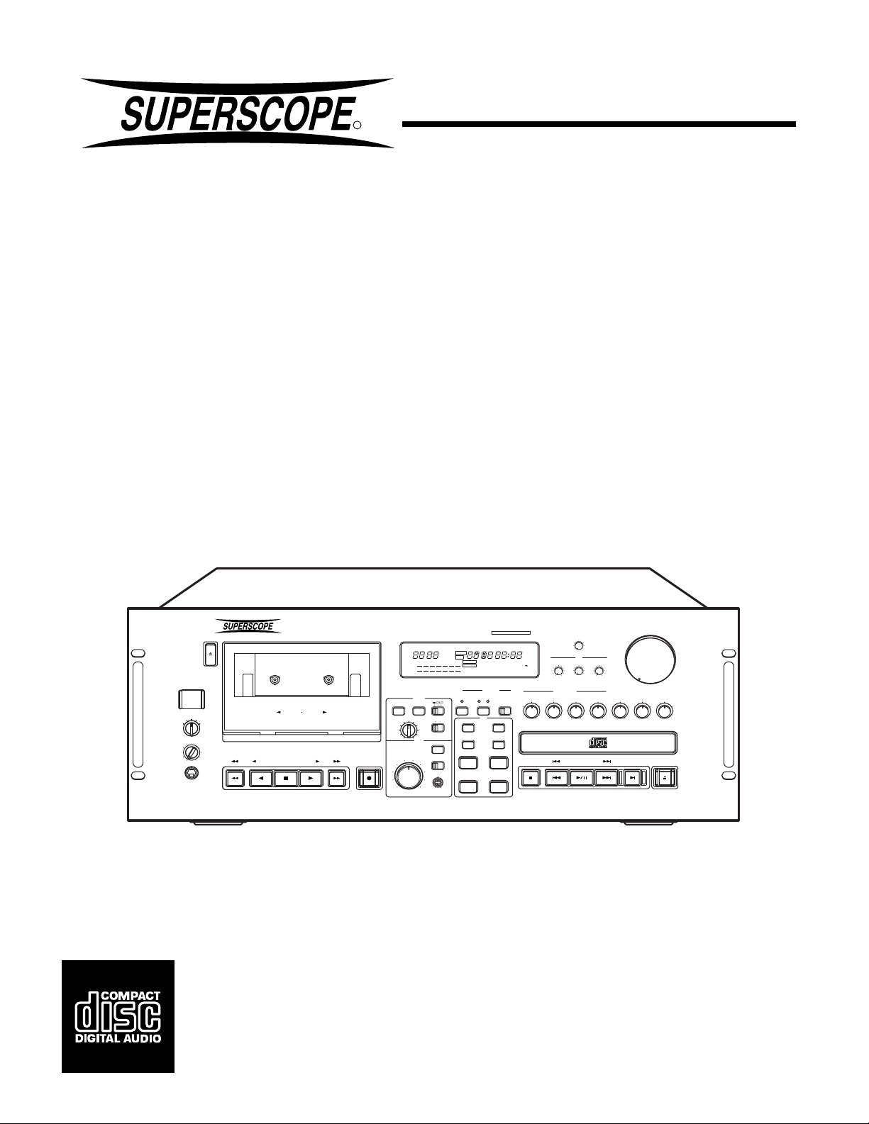
PAC750
PAC770
Professional
CD/Cassette/Mixer/
System
Professional
CD/Cassette/Mixer/
Amplifier System
MIC/LINE
POWER
HP SELECT
HP LEVEL
HEADPHONE
PAC770
EJECT
QUICK REVERSE
TAPE
AUXCD
SYSTEM
AUTOMATIC TAPE SELECT SYSTEM
PLAY PLAY
STOP
MEMO
REC
3
2
1
HX
PRO
MEMO
DUBBNRDOLBY
H-SP
L
-10-15-20
R
TAPE
RESET
DOLBY NR
PITCH
OFF B C
REC
AUTO DUBB
LEVEL
AUTO LEVEL
ON
OFF
654
7
BALANCE
8
9
L
R
10
0
DOLBY B-C NR HX PRO
2
AUTO
MEMO
STEREO
TRACK
BC
PRESET
REPEAT1
+30-3-6
CD+TAPE+AUX
VOICE
DUCKING
REDUCTION
-15
PROGRAM
REPEAT
KEY
DOWN
MHz
kHz
TOTAL
REM
PROGRAM
A-B
20
19181716151413121110
987654321
MIC/LINE
AUTO
AUTO
GAIN
-
∞
OFF
ON
CD
TIME
A-B
UP
STOP
TEMPO
LOW
MIC/LINE
BALANCE
PLAY/PAUSE
EQ
HIGH
MID
4
321
VOLUME
5
6
4
3
2
1
TAPE
SINGLE
PLAY
7
8
9
0
10
AUX
CD
OPEN/CLOSE
Owners Manual
1
CAUTION
RISK OF ELECTRIC SHOCK
DO NOT OPEN
CAUTION: TO REDUCE THE RISK OF ELECTRIC SHOCK,
DO NOT REMOVE COVER (OR BACK)
NO USER-SERVICEABLE PARTS INSIDE
REFER SERVICING TO QUALIFIED SERVICE PERSONNEL
The lightning flash with arrowhead symbol, within
an equilateral triangle, is intended to alert the user
to the presence of uninsulated “dangerous voltage”
within the product’s enclosure that may be of sufficient magnitude to constitute a risk of electric shock
to persons.
The exclamation point within an equilateral triangle
is intended to alert the user to the presence of
important operating and maintenance (servicing)
instructions in the literature accompanying the
appliance.
WARNING
TO REDUCE THE RISK OF FIRE OR ELECTRIC SHOCK,
DO NOT EXPOSE THIS APPLIANCE TO RAIN OR MOISTURE.
NOTE:
This equipment has been tested and found to comply
with the limits for a Class B digital device, pursuant to
Part 15 of the FCC Rules. These limits are designed to
provide reasonable protection against harmful interference in a residential installation. This equipment generates, uses and can radiate radio frequency energy and,
if not installed and used in accordance with the instructions, may cause harmful interference to radio communications. However, there is no guarantee that interference
will not occur in a particular installation. If this equipment
does cause harmful interference to radio or television
reception, which can be determined by turning the equipment off and on, the user is encouraged to try to correct
the interference by one or more of the following measures:
– Reorient or relocate the receiving antenna.
– Increase the separation between the equipment and
receiver.
– Connect the equipment into an outlet on a circuit
different from that to which the receiver is connected.
– Consult the dealer or an experienced radio/TV techni-
cian for help.
NOTE:Changes or modifications may cause this unit
to fail to comply with Part 15 of the FCC Rules and may
void the user's authority to operate the equipment.
This Class B digital apparatus meets all
requirements of the Canadian InterferenceCausing Equipment Regulations.
Cet appareil numérique de la Classe B respecte
toutes les exigences du Règlement sur le matérier
brouilleur du Canada.
2
SAFETY
INSTRUCTIONS
READ BEFORE OPERATING EQUIPMENT
This product was designed and manufactured to meet strict
quality and safety standards. There are, however, some installation and operation precautions which you should be particularly aware of.
1. Read Instructions — All the safety and operating instructions should be read before the appliance is operated.
2. Retain Instructions — The safety and operating instructions should be retained for future reference.
3. Heed Warnings — All warnings on the appliance and in
the operating instructions should be adhered to.
4. Follow Instructions — All operating and use instructions
should be followed.
5. Water and Moisture — The appliance should not be used
near water — for example, near a bathtub, wash-bowl,
kitchen sink, laundry tub, in a wet basement, or near a
swimming pool, etc.
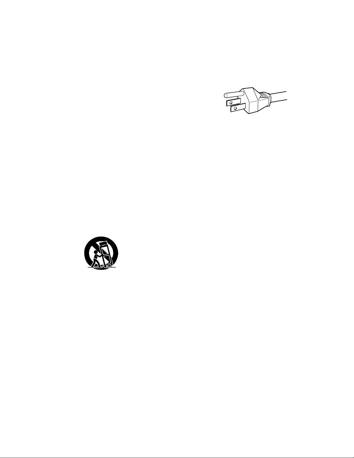
6. Carts and Stands — The appliance should be used only
with a cart or stand that is recommended by the manufacturer.
7. An appliance and cart combination should be moved with
care. Quick stops, excessive force, and uneven surfaces
may cause the appliance and cart combination to overturn.
8. Wall or Ceiling Mounting — The appliance should be
mounted to a wall or ceiling only as recommended by the
manufacturer.
9. Ventilation — The appliance should be situated so that its
location or position does not interfere with its proper ventilation. For example, the appliance should not be situated
on a bed, sofa, rug, or similar surface that may block the
ventilation openings; or, placed in a built-in installation,
such as a bookcase or cabinet that may impede the flow
of air through the ventilation openings.
10. Heat — The appliance should be situated away from heat
sources such as radiators, heat registers, stoves, or other
appliances (including amplifiers) that produce heat.
11. Power Sources — The appliance should be connected to
a power supply only of the type described in the operating
instructions or as marked on the appliance.
12. Grounding or Polarization — The precautions that should
be taken so that the grounding or polarization means of an
appliance is not defeated.
13. Power-Cord Protection — Power-supply cords should be
routed so that they are not likely to be walked on or pinched
by items placed upon or against them, paying particular attention to cords at plugs, convenience receptacles, and the
point where they exit from the appliance.
14. Cleaning — The appliance should be cleaned only as recommended by the manufacturer.
15. Nonuse Periods — The power cord of the appliance should
be unplugged from the outlet when left unused for a long
period of time.
16. Object and Liquid Entry — Care should be taken so that
objects do not fall and liquids are not spilled into the enclosure through openings.
17. Damage Requiring Service — The appliance should be
serviced by qualified service personnel when:
A. The power-supply cord or the plug has been damaged;
or
B. Objects have fallen, or liquid has spilled into the appli-
ance; or
C. The appliance has been exposed to rain; or
D. The appliance does not appear to operate normally or
exhibits a marked change in performance; or
E. The appliance has been dropped, or the enclosure
damaged.
18. Servicing — The user should not attempt to service the
appliance beyond that described in the operating instructions. All other servicing should be referred to qualified service personnel.
3

LASER SAFETY
This unit employs a laser. Only a qualified service
person should remove the cover or attempt to service
this device, due to possible eye injury.
CAUTION :
USE OF CONTROLS OR ADJUSTMENTS
OR PERFORMANCE OF PROCEDURE
OTHER THAN THOSE SPECIFIED HEREIN
MAY RESULT IN HAZARDOUS RADIATION
EXPOSURE.
4

TABLE OF CONTENTS
FRONT AND REAR PANEL DRAWINGS ....................................................................... 5
SPECIFICATIONS ........................................................................................................... 6
INTRODUCTION ............................................................................................................. 8
PRECAUTIONS............................................................................................................... 8
FEATURES...................................................................................................................... 8
REAR PANEL CONNECTIONS ...................................................................................... 9
FRONT PANEL FEATURES ......................................................................................... 10
OPERATION.................................................................................................................. 13
MIXER OPERATION ..................................................................................................... 13
The Mixer In Relation To The Tape Deck ............................................................. 13
CASSETTE DECK OPERATION................................................................................... 13
Cassette Tape Playback ....................................................................................... 13
Searching For Tracks ............................................................................................ 13
Rewind & Fast Forward......................................................................................... 13
Cassette Tape Record .......................................................................................... 13
Erasure Of Tape.................................................................................................... 13
To Protect Valuable Recordings ........................................................................... 13
Auto Tape Selector ............................................................................................... 13
CD PLAYER OPERATION ............................................................................................ 14
CD Playback ......................................................................................................... 14
Selecting The Playback Track............................................................................... 14
A-B Repeat............................................................................................................ 14
Programming Playback Tracks ............................................................................. 14
ENGLISH
Tempo Control ...................................................................................................... 14
Key Control ........................................................................................................... 15
CD-RW/CD-R Playback ........................................................................................ 15
CD TO TAPE DUBBING ................................................................................................ 15
Manual Record Level Dubbing .............................................................................. 15
Automatic Record Level Dubbing.......................................................................... 15
TROUBLESHOOTING................................................................................................... 16
REPAIRS ....................................................................................................................... 16
CLEANING OF EXTERIOR SURFACES ...................................................................... 16
COMPACT DISC CARE ................................................................................................ 17
CASSETTE TAPE CARE .............................................................................................. 17
BASIC HOOKUP ........................................................................................................... 51
PAC750 ................................................................................................................. 51
PAC770 ................................................................................................................. 52
7
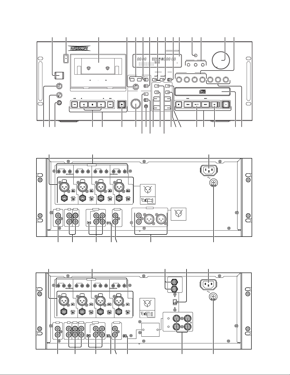
PAC750/PAC770 FRONT PANEL
!
@
@6@
@
!4#1#0@9@
qut
EJECT
POWER
CD
AUXTAPE
MIC/LINE
HP SELECT
HP LEVEL
HEADPHONE
!8
@2!9
PAC750 REAR PANEL
EQ EQ
LOW
INPUT 4
AUX
IN IN
L
L
R
R
ew
PAC770
QUICK REVERSE
SYSTEM
AUTOMATIC TAPE SELECT SYSTEM
PLAY PLAY
STOP
REC
n r mopr!6 !7
MIC/LINE
EQ
EQ
PAN PANPAN
HIGH
LLRL
PUSH
NEUTRIK
PHANTOM
ONOFF
MIC
LOW
HIGH
CD
TAPE
OUT
OUT
L
R
RLR
HIGH
LOW
NEUTRIK NEUTRIK NEUTRIK
PHANTOM PHANTOM
OFF ON
LINE
MIC
ONOFF
PAN
HIGH
LOW
INPUT 2 INPUT 1INPUT 3
PUSHPUSH
LINE
LOW
EFFECT
OUT
L
R
HIGH
LOW
PUSH
48V 48V48V48V
PHANTOM
OFF ON
MIC
LINE
MIC
LOW
HIGHHIGH
SENSITIVITIYSENSITIVITIY SENSITIVITIYSENSITIVITIY
MPX
FILTER
ONOFF
HIGH
REMOTE
IN
OUT
3
DOLBY B-C NR HX PRO
2
HX
PRO
AUTO
MEMO
MEMO
STEREO
TOTAL
DUBBNRDOLBY
H-SP
L
-10-15-20
R
TAPE
RESET
MEMO
DOLBY NR
PITCH
OFF B C
REC
AUTO DUBB
LEVEL
AUTO LEVEL
OFF
654
7
3
BALANCE
8
2
9
1
L
0
10
TRACK
BC
PRESET
REPEAT1
A-B
+30-3-6
987654321
CD+TAPE+AUX
VOICE
AUTO
DUCKING
REDUCTION
-
∞
-15
CD
TIME
PROGRAM
A-B
REPEAT
ON
UP
TEMPO
KEY
DOWN
R
1
MHz
kHz
REM
PROGRAM
MIC/LINE
AUTO
GAIN
OFF
ON
LOW
20
19181716151413121110
MIC/LINE
STOP
BALANCE
PLAY/PAUSE
7
8
VOLUME
5
4
EQ
MID
321
3
2
HIGH
1
0
4
TAPE
CD
SINGLE
OPEN/CLOSE
PLAY
5
6
7
8
9
10
AUX
i@3!1o!0 @0 @4
y!5
!2
IML
R
1
2
+
GND
ONOFF
3
UNBALANCED
OUT
L
R
-
COLD
HOT
COMMON
SYSTEM
NEUTRIK
R
BALANCED
OUT
L
NEUTRIK
+2GND
3
-
1
LINE
LOW
S
U
E
F
A BCDE H
PAC770 REAR PANEL
EQ EQ
LOW
INPUT 4
AUX
IN IN
L
R
R
AB CDEF G
MIC/LINE
EQ
EQ
PAN PANPAN
HIGH
LOW
NEUTRIK NEUTRIK NEUTRIKNEUTRIK
LINE
PRE-AMP
RLR
PHANTOM
OFF ON
MIC
ONOFF
LLRL
HIGH
PHANTOM
ON
OFF
MIC
LOW
HIGH
CD
TAPE
OUT
OUT OUT
LL
R
PAN
HIGH
LOW
INPUT 2 INPUT 1INPUT 3
LINE
LOW
EFFECT
OUT
L
R
HIGH
LOW
PUSHPUSHPUSHPUSH
48V 48V48V48V
PHANTOM
OFF ON
MIC
LINE
MIC
LOW
HIGHHIGH
SENSITIVITIYSENSITIVITIY SENSITIVITIYSENSITIVITIY
REMOTE
IN
MPX
FILTER
ONOFF
MONO
BRIDGE
OUT
OFF
N
KJIML
SPEAKER
(4ΩMIN)
L
SPEAKER
(4ΩMIN)
R
S
U
E
F
LR
+
-
R
2
PHANTOM
ONOFF
LINE
HIGH
LOW
ON
1
+
GND
3
-
COLD
HOT
COMMON
MONO BRIDGE ON:
CONNECT
++
R AND L
TO SPEAKER
(8Ω MIN)
SPEAKER
SELECT
H
5

SPECIFICATIONS
MIXER
Input sensitivity
MIC HIGH ................................................................................................................................................................................................ 4mV
MIC LOW ............................................................................................................................................................................................... 40mV
LINE ................................................................................................................................................................................................... 1000mV
PHANTOM output voltage .........................................................................................................................................................................DC 48V
Input
AUX in ...................................................................................................................................................................................... 1000mV/47kΩ
Pre-Out Output Level / Impedance (PAC770 Only) .................................................................................................................. 200mV / 1.5kohm
System (RCA) Output Level / Impedance (PAC750 Only) ...................................................................................................... 1000mV / 1.5kohm
System (XLR) Output Level / Imnpedance (PAC750 Only) ...................................................................................................... 1000mV / 150ohm
EQ - MASTER & MIC/LINE
Low Band Center .................................................................................................................................................................................. 100Hz
Mid Band Center .................................................................................................................................................................................... 1kHz
High Band Center ................................................................................................................................................................................. 15kHz
POWER AMPLIFIER (PAC770 Only))
Power output (RMS Continuous <0.08% THD)
Stereo 8ohm Load ....................................................................................................................................................................... 90W + 90W
Stereo 4ohm Load ................................................................................................................................................................... 110W + 110W
Mono 8ohm Load .................................................................................................................................................................................. 210W
Frequency response ............................................................................................................................................................ 5Hz-30kHz (+/- 3dB)
Rated input level ...................................................................................................................................................................................... 0.5Vrms
TAPE DECK
Track System ........................................................................................................................................................................... 4 Track, 2 Channel
Record/Erasure system ................................................................................................................................................................ AC105kHz Bias
Head System (Rotary type combination)
Rec/Play ............................................................................................................................................................................... Hard metal alloy
Erase ..................................................................................................................................................................................... Dual gap ferrite
Motor System
Capstan .............................................................................................................................................................................. DC Servo Control
Reel ........................................................................................................................................................................................................... DC
Wow and Flutter (JIS weighted) ................................................................................................................................................................ <0.07%
Frequency Characteristics
Frequency responese (no Dolby NR)
type 1 (Normal position) .................................................................................................................................................. 40Hz-15kHz± 3dB
type 2 (High position) ...................................................................................................................................................... 40Hz-16kHz± 3dB
type 3 (Metal position) ..................................................................................................................................................... 40Hz-16kHz±3dB
Overall S/N (no Dolby NR, IEC-A WTD)
type 1 (Normal position) ...................................................................................................................................................................... 53dB
type 2 (High position) .......................................................................................................................................................................... 54dB
type 3 (Metal position) ......................................................................................................................................................................... 55dB
Dolby NR effect (B/C S/N improvement, CCIR-ARM WTD) .................................................................................................................. 9dB/18dB
Analog output
Output level .................................................................................................................................................................................. 500mV
Output impedance .............................................................................................................................................................................1kΩ
CD
Channels ............................................................................................................................................................................................. 2 channels
Sampling frequency ................................................................................................................................................................................. 44.1kHz
Quantization .......................................................................................................................................................................... 16bit linear/channel
Error correction ............................................................................................................................... Cross-interleave read solomon code (CIRC)
D/A conversion ....................................................................................................................................................................... 1-bit linear/channel
Wow & flutter ........................................................................................................................................................................... Precision of quartz
Optical Readout System
Laser .......................................................................................................................................................................... GaAlAs semiconductor
Wavelength .......................................................................................................................................................................................... 780nm
Frequency Characteristics (Tempo control off)
Frequency response ...................................................................................................................................................... 20Hz-20kHz -1.5dB
Dynamic range ...................................................................................................................................................................................... 80dB
S/N ratio ................................................................................................................................................................................................. 70dB
Channel separation ............................................................................................................................................................................... 70dB
Distortion (THD 1kHz) ........................................................................................................................................................................... 0.05%
Analog output
Output level ....................................................................................................................................................................................... 2V RMS
Output impedance ................................................................................................................................................................................1.5kΩ
COMMON PART:
Power Consumption
PAC770 ................................................................................................................................................................................................. 500W
PAC750 ................................................................................................................................................................................................... 30W
Dimensions
Width ............................................................................................................................................................................... 19 inches (483mm)
Height (4U) ........................................................................................................................................................................ 7 inches (180mm)
Depth ............................................................................................................................................................................... 18 inches (455mm)
Net Weight ................................................................................................................................................................ PAC770 ..: 39.7 lbs (18kg)
These specifications represent design standards, Higher levels of performance can be expected under most conditions.
PAC750 : 26.4 lbs (12kg)
Subject to change without prior notice.
6

INTRODUCTION
Thank you for selecting the Superscope PAC750/PAC770. Please read
these operating instructions carefully. We recommend that you read the
entire user guide prior to connecting and operating the unit. It is also
recommended that all connections be made prior to operating the unit.
Please refer to this manual to identify controls and connections for
operation of the unit.
ENGLISH
PRECAUTIONS
The following precautions should be considered when operating the
equipment.
When setting the equipment ensure that :
– air is allowed to circulate freely around the equipment
– the equipment is on a vibration free surface
– the equipment will not be exposed to interference from an external
source
– the equipment will not be exposed to excessive heat, cold, moisture
or dust
– the equipment will not be exposed to direct sunlight
– the equipment will not be exposed to electrostatic discharges
¡In addition, never place heavy objects on the equipment.
¡If a foreign body or water does enter the equipment, contact your
nearest dealer or service center.
¡Do not pull out the plug by pulling on the mains lead. Hold the plug.
FEATURES
BUILT-IN MIXER
The PAC750/PAC770 incorporate a built-in mixer that includes inputs
and control for the built-in Tape and CD players, the stereo Aux input,
and the 4 mono Mic/Line inputs. The Aux input allows an unbalanced
stereo line level source to be connected. The 4 mono Mic/Line inputs
allow either a microphone (either high or low sensitivity) or line input to
be connected. EQ and pan controls are provided on those inputs to
allow for feedback elimination and mixer customization.
AUTO DUCKING
The PAC750/PAC770 incorporate an Auto Ducking feature that allows
the Mic/Line inputs to work in conjunction with the Tape, CD, and Aux
inputs. With the Auto Ducking feature set to -15dB, everything works as
normal except for when any of the Mic/Line inputs has an active signal.
When this occurs, the Tape, CD, and Aux inputs drop down in level by
-15dB. When Auto Ducking is set to -∞, the Tape, CD, and Aux inputs
are dropped out completely when the Mic/Line inputs are active.
VOICE REDUCTION
The Tape, CD, and Aux inputs to the mixer contain a Voice Reduction
circuit that can effectively reduce the vocal tracks in most music. Please
be aware that results vary according to the music and the way it was
recorded.
AMPLIFIER (PAC770)
The PAC770 contains a powerfull amplifier that allows versatile speaker
connection. The 1/4" connectors are very convenient for portable use
while the binding posts allow connection of single-ended banana plugs
or a secure bare wire connection.
TEMPO CONTROL
The PAC750/PAC770 CD player allows for the adjustment of the playing
speed (Tempo) from -50% to +50%. This feature is similar to Pitch
control except that the Key (musical pitch) of the CD output does not
change when the Tempo is adjusted.
KEY CONTROL
The PAC750/PAC770 CD player allows for the adjustment of the Key
(frequency/musical pitch) from -1 octave to +1 octave during playback.
This feature allows the music to be adjusted in order to match correctly
to an instrument or a voice.
A-B LOOP
The PAC750/PAC770 allows two points within the CD to be selected and
the audio within these points will be repeated until a stop command is
issued.
SINGLE TRACK PLAY
The PAC750/PAC770 can be set for the CD player to play the selected
track and then stop and cue up the next track.
AUTO CUE
This feature allows the CD player to advance to the beginning of the
audio within the track rather than start from the track start flag. This
feature helps to minimize the silence at the beginning of a CD track.
PITCH CONTROL
The PAC750/PAC770 tape player allows for adjustment of the playback
pitch (key + tempo) from -12% to +12%. The feature is particularly useful
to tune a tape to accompanying instruments and choirs.
QUICK OPTICAL AUTOREVERSE
In addition to the normal tension reversing circuitry the PAC750/PAC770
tape transport also employs optically sensing quick autoreverse circuitry. This circuitry reacts to the clear areas of the tape, usually the
leader tape, and when detected will reverse the direction of the tape
transport. This process minimizes the lose of signal being recorded or
played back. This reverse process applies to all tape playback and
recording modes, including autoreverse and continuous mode.
DOLBY NR SYSTEMS
The Dolby Noise Reduction systems compress and amplifies the input
signal during recording in order to raise the signal-to-noise ratio on the
tape. During playback, these signals are expanded and attenuated by
the same amount in order to regain the original dynamic range of the
music. An additional result of this expansion and attenuation is that the
noise floor of the recording is reduced significantly. Dolby B typically
reduces noise by 10dB and Dolby C typically reduces noise by 20 dB.
DOLBY HX PRO HEADROOM EXTENSION
The Dolby HX PRO system monitors the total amount of effective bias
during recording and instantaneously compensates for any excess bias
by reducing the tape deck’s bias signal level accordingly. The system
operates independently on each channel. HX Pro is unlike a noise
reduction system because it functions only during recording and no
decoding is required. Therefore a tape recorded with the HX Pro system
can be played back on any other cassette deck while retaining the
benefits of HX Pro.
ONE TOUCH DUBBING
The PAC750/PAC770 allows dubbing of the CD to the tape with one
button start control. This feature allows manual or automatic record level
control.
RC5 REMOTE CONTROL COMPATIBILITY
The PAC750/PAC770 comes equipped with an RC5 remote in and out
port. Through the use of various remote control options, major functions
of the unit can be operated via wired or wireless remote control.
8

REAR PANEL CONNECTIONS
A AUX INPUT JACKS
These jacks should be connected to the LINE OUTPUT of your
source.
B LINE OUTPUT (CD, TAPE, PRE-AMP(MIX)) JACKS
These jacks can be connected to the appropriate LINE INPUT of a
power amp, PA or monitoring system.
C EFFECT INPUT & OUTPUT JACKS
These jacks are used to connect to a graphic equalizer or an effects
processor. When such a device is connected, set the EFFECT
switch to the ON position. When such a device is not connected, set
the EFFECT switch to the OFF position.
¡If the switch is left ON without anything connected, no audio will be
output through the pre-out or the speakers.
D MPX FILTER SWITCH
When recording FM broadcasts, set this switch to the ON position to
eliminate the FM carrier signal.
E REMOTE CONTROL JACKS
These jacks are used with an infrared or wired remote control to
provide remote operation of the PAC750/PAC770.
The signal format of this interface is Philips RC5.
¡These jacks can be serially linked to provide serial remote control
operation of multiple RC5 equipped products as well.
F MONO BRIDGE SWITCH (PAC770)
¡This switch is used to select between mono bridge and stereo
amplified output mode.
When this switch is in the OFF position, the unit functions as a stereo
power amp. When this switch is in the ON position, the unit functions
as a monaural amp. (For details on how to connect the speakers,
refer to page 52.)
¡This switch only effects the binding post speaker outputs and not the
1/4” speaker outputs.
¡Make sure this switch is OFF when the 1/4” speaker outputs are
used.
G, K AMPLIFIED SPEAKER OUTPUTS (PAC770)
These jacks are used to connect to passive (non-powered) speakers.
When using a speaker system in stereo mode with left and right
channels, connect the right channel speaker to the output terminal
G labeled “R,” and the left channel speaker to the output terminal G
labeled “L”. In stereo mode, use a speaker system with an impedance
of 4 to 16 ohms.
When using a single (mono) speaker system, set the MONO BRIDGE
switch to “ON”. Connect the speaker to the red terminals for both the
“L” and “R” speaker terminals G. Do not use the black terminals. In
mono mode, use a speaker system with an impedance of 8 to 16
ohms.
¡MONO BRIDGE mode is only available on the binding post speaker
outputs and not the 1/4” speaker outputs.
H FUSE Holder
CAUTION : Disconnect AC power before removing.
This receptacle holds a specific fuse that is used to prevent overload
and shorting.
I AC TERMINAL
Connect the AC cord that is provided with the unit to this terminal.
J SPEAKER SELECT SWITCH (PAC770)
This switch is used to select between the two sets of speaker
terminals (K and G).
¡Speaker terminals K and G cannot both be used simultaneously.
¡Speaker terminal K does not permit mono bridge connection.
However, make sure the MONO BRIDGE switch is in the OFF
position.
L EQ & PAN CONTROLS
The recessed EQ controls allow the tone of each MIC/LINE input to
be adjusted to obtain optimum sound quality. Turning each control
to the right boosts the corresponding frequency range and to the left
attenuates it.
LOW : Controls the tone of the lower frequencies. (100Hz)
HIGH : Controls the tone of the higher frequencies. (15kHz)
The recessed PAN control adjusts the MIC/LINE input to the desired
position (L, R or L + R) in the mixing bus.
When the knob is at the center position, the MIC/LINE signal is
centered between the left and right. To position the output on the left
side, turn the knob towards “L”. To position the output on the right
side, turn the knob towards “R”.
M MIC/LINE INPUT JACKS
Each set of these inputs is designed to accept either a microphone
(MIC) or line (LINE) level signal. All of the input jacks are balanced.
For a microphone level signal, set the MIC ⇔ LINE switch to the MIC
position. For all MIC inputs, set the SENSITIVITY to either HIGH or
LOW, according to the sensitivity of the microphone. If a microphone
that requires phantom power is used with the XLR input, set the
PHANTOM switch to the “ON” position.
For a line level input, set the MIC ⇔ LINE switch to the LINE position.
¡The XLR input and the 1/4” input cannot be used at the same time.
N SYSTEM OUTPUT JACKS (PAC750)
The system output jacks are the final output of the mixer and can be
used when connecting the PAC750 to a power amp, PA, or monitoring
system. The RCA jacks are unbalanced outputs. The XLR jacks are
balanced outputs.
ENGLISH
9

FRONT PANEL FEATURES
q POWER BUTTON
Push this switch in to turn the unit on and off. When power is turned
off, all past settings are removed from memory and the unit returns
to its default setting upon the next power up.
w CASSETTE TAPE HOLDER
ENGLISH
This holds the cassette tape for playback and record functionality.
Tapes that have the record protect tab removed will not enter into the
record mode.
e EJECT BUTTON
Press this button to open the cassette tape holder.
r TAPE DECK AND CD PLAYER CONTROL
TAPE DECK CONTROL BUTTONS
77
7 STOP BUTTON
77
Press this button to cancel all current operations of the tape deck.
33
3 FORWARD PLAY BUTTON
33
Press this button to engage the tape deck into the forward play
function.
22
2 REVERSE PLAY BUTTON
22
Press this button to engage the tape deck into the reverse play
function.
11
1 REWIND BUTTON
11
Press this button to engage the tape transport into the fast rewind
mode from the right (take-up) to the left (supply) reels. When this
button is pressed during playback, the tape deck will search for the
next program in the reverse direction.
¡¡
¡ FAST FORWARD BUTTON
¡¡
Press this button to engage the tape transport into the fast forward
wind mode from the left (supply) to the right (take-up) reels. When
this button is pressed during playback, the tape deck will search for
the next program in the forward direction.
¶¶
¶ REC/PAUSE BUTTON
¶¶
Press this button to engage the tape transport into the record-pause
mode. In this mode the tape deck is ready to begin recording. The
tape record mode can be engaged by pressing the FORWARD
PLAY 3 or REVERSE PLAY 2 buttons.
CD PLAYER CONTROL BUTTONS
44
4 PREVIOUS/REVERSE SEARCH BUTTON
44
When this button is pressed during the stop mode, tracks can be
selected for playback by searching in the reverse order, starting
from the last track on the disc.
When this button is pressed during the play mode, the CD player will
skip back to the beginning of the current track. If immediately
pressed again, the CD player will skip back one track for every time
the button is pushed.
During the program mode, this button is used to select the tracks to
be saved in the program.
If this button is pressed and held during playback, the CD player will
enter audible reverse search mode until the button is released.
¢¢
¢ NEXT/FORWARD SEARCH BUTTON
¢¢
When this button is pressed during the stop mode, tracks can be
selected for playback by searching in the forward direction, starting
from track number 1.
When this button is pressed during the play mode, the CD player will
skip forward one track for every time the button is pushed.
During the program mode, this button is used to select the tracks to
be saved in the program.
If this button is pressed and held during playback, the CD player will
enter the audible forward search mode until the button is released.
SINGLE PLAY BUTTON
Press this button to toggle the Single Track Play feature on and off.
When on, the TRACK (g) indicator in the display will flash and, during
playback only, the Single Play button will light. When the CD player
is stopped, only the TRACK inicator will flash to indicate that the
Single Track play mode is active. The Single Track button will not
light so it does not look like the CD player is playing while it is
stopped.
Once the Single Track play mode has been activated, it will stay on,
even if discs are changed, until it is turned off or the power has been
switched off.
When Single Track Play is activated, the CD player will do two things
differently than normal: first, each time a track is selected via the 4
and ¢ buttons, the track will not start playing but will enter the
Pause mode at the beginning of the audio (cued up). Second, when
a track that is playing comes to an end, the next track will not start
playing but will be cued up to the audio in Pause mode.
¡While the CD player is stopped, Single Track play can be turned on
and off but is only indiated by the flashing TRACK (g) indicator.
Once playback starts, the Single Play button will light.
¡Single Track play can be switched on or off at any time by pressing
the Single Track button.
00
0 OPEN/CLOSE BUTTON
00
Press this button to open the CD door and eject the disk. Press this
button again to close the CD door and read the disc.
¡The OPEN/CLOSE button is disabled during the play mode.
77
7 STOP BUTTON
77
Press this button to stop the CD player while in the play mode. During
the program mode, the STOP button will cancel the current program
when the CD player is in the stop mode.
66
6 PLAY/PAUSE BUTTON
66
When this button is pressed during the stop mode, the CD player will
start playback from the beginning of the disc or program, and then
continue to play until the end of the disc or program.
When this button is pressed during the play mode, the CD player will
enter the pause mode.
When this button is pressed during the pause mode, the CD player
will enter the play mode.
t TAPE COUNTER BUTTON
MEMO BUTTON
Press this button to store the current tape location into the counter
memory. Once this memory point is set, the tape deck will rewind or
fast forward until it reaches this point in the tape and will stop. To
clear the memory press the MEMO button again.
RESET BUTTON
Press this button to reset the current tape counter reading from its
existing point to “0000”.
y AUTO DUBB BUTTON
Press this button to engage the tape transport into the dubbing
mode from the CD player.
¡See page 15 for more information on the operation of this function.
10

u TAPE PITCH KNOB
Rotate this knob to adjust the tape deck playback pitch (key +
tempo) from -12% to +12%. While the control is in the center detent
position, the tape deck is at normal (0% variance) pitch.
¡This control has no effect on the tape pitch during the record mode.
i KEY BUTTONS
These buttons can be used to change the key (frequency/musical
pitch) of the sound from the CD by up to ±1 octave.
The “+” key raises the key in 12 1/2 cent increments. Press and hold
the “+” button to quickly increase the key.
The “–” key lowers the key in 12 1/2 cent increments. Press and hold
the “–”button to quickly decrease the key.
Press both “+” and “–” at the same time to quickly return the key back
to 0.00 position (normal key).
¡See page 15 for more information on the operation of this function.
o TIME BUTTON
By pressing the TIME button you can toggle the CD player time
display with the following. Normal (no indication) - Displays the time
elapsed within the current track being played. REM- Displays the
remaining time left of the current track being played. TOTAL REMDisplays the total time remaining on the current disc being played.
!0 REPEAT BUTTON
This button can be used to set the CD player in all track or single track
repeat play mode. The first press of the REPEAT button places the
CD player in the all track repeat mode and the “REPEAT” indicator
will light in the display. The second press of the REPEAT button
places the CD player in single track repeat mode and the “REPEAT”
and “1” indicator will light in the display. The third press of the
REPEAT button will exit all repeat play modes.
!3 REVERSE MODE SWITCH
This switch sets the automatic tape direction of the tape transport
during playback, normal recording, or dubbing.
: One-way mode.
In this position the tape will play or record one side of the tape
and stop.
: Two-way mode.
In this position the tape will play or record both sides of the tape
and stop.
: Continuous mode
In this position the tape will play the tape in a continuous loop
until the stop command is given. In the record mode the tape will
record both sides of the tape and stop.
!4 DOLBY NOISE REDUCTION SWITCH
This switch allows for the encoding or decoding of Dolby B or C
Noise Reduction. When recording with Dolby Noise Reduction,
select the type (B or C) of noise reduction desired and place the
switch in the appropriate position. When playing a tape with Dolby
Noise Reduction encoded onto it, place this switch in the same
position (B or C) as it was recorded in.
!5 ALC (AUTOMATIC RECORD LEVEL CONTROL) SWITCH
This switch performs automatic control of the input level during
recording. When this switch is set to the OFF position, the recording
level is controlled by the record level knob. When this switch is set
to the ON position, the record level is set automatically and the
record level knob is disabled.
!6 RECORD LEVEL KNOB
This knob controls the record level up or down during manual
recording.
ENGLISH
!1 A-B BUTTON
This button allows you to repeat a specific section in the current CD
track that is being played. When this control is pressed the first time,
the A-B indicator flashes and this position on the track is noted as the
start or A point.
When this control is pressed again, the A-B indicator lights
continuously, and this position on the track is noted as the end or B
point. After setting the end point, the CD player returns to the start
point (A), and plays until it reaches the end point (B). The CD player
will repeat this function until the STOP or REPEAT button is pressed.
Subsequent press of this button will change the B point into the A
point and allow a new B point to be set.
¡See page 14 for more information on the operation of this function.
!2 PROGRAM BUTTON
When this button is pressed once, the CD player enters the program
entry mode and the program indicator will begin to flash. Pressing
the PROGRAM button again will return the CD player to the normal
play mode.
¡See page 14 for more information on the operation of this function.
!7 RECORD BALANCE CONTROL
This recessed control allows for the adjustment of the record level
between the left and right channels. By using a phillips type
screwdriver, you can adjust this balance control between left (counterclockwise) and right (clockwise).
!8 HP (HEADPHONE) SELECT SWITCH
This switch is used to select which source is monitored through the
headphone jack.
!9 HEADPHONE JACK
This output jack is used to connect to a set of headphones.
¡This jack requires a 1/4” type connector.
@0 CD TRAY
The CD tray is used to hold a CD for playback.
11
 Loading...