


Manitowoc Ice UD0140A, UD0140W, UD0140AE, UY0140A, UY0140W Operator’s Manual
... Manitowoc

UnderCounter
Ice Machines
Installation, Use & Care Manual
This manual is updated as new information and models are released.
Visit our website for the latest manual. www.manitowocice.com
America’s #1 Selling Ice Machine
Part Number 040002909 Rev02 4/15

Table of Contents
Section 1 |
|
General Information |
|
Model Numbers . . . . . . . . . . . . . . . . . . . . . . . . . . . . . . . . . . . . . . . . . . . . . . . . . . . . |
3 |
Accessories . . . . . . . . . . . . . . . . . . . . . . . . . . . . . . . . . . . . . . . . . . . . . . . . . . . . . . . |
5 |
Bin Caster . . . . . . . . . . . . . . . . . . . . . . . . . . . . . . . . . . . . . . . . . . . . . . . . . . . . . |
5 |
Arctic Pure Water Filter System . . . . . . . . . . . . . . . . . . . . . . . . . . . . . . . . . . . . |
5 |
Manitowoc Cleaner and Sanitizer . . . . . . . . . . . . . . . . . . . . . . . . . . . . . . . . . . . |
5 |
Section 2 |
|
Installation Instructions |
|
Location of Ice Machine . . . . . . . . . . . . . . . . . . . . . . . . . . . . . . . . . . . . . . . . . . . . . |
7 |
Ice Machine Heat of Rejection . . . . . . . . . . . . . . . . . . . . . . . . . . . . . . . . . . . . . . . . |
7 |
Leveling the Ice Machine . . . . . . . . . . . . . . . . . . . . . . . . . . . . . . . . . . . . . . . . . . . . . |
7 |
Electrical Service . . . . . . . . . . . . . . . . . . . . . . . . . . . . . . . . . . . . . . . . . . . . . . . . . . . |
8 |
General . . . . . . . . . . . . . . . . . . . . . . . . . . . . . . . . . . . . . . . . . . . . . . . . . . . . . . . |
8 |
Voltage . . . . . . . . . . . . . . . . . . . . . . . . . . . . . . . . . . . . . . . . . . . . . . . . . . . . . . . |
8 |
Fuse/Circuit Breaker . . . . . . . . . . . . . . . . . . . . . . . . . . . . . . . . . . . . . . . . . . . . . |
8 |
Total Circuit Ampacity . . . . . . . . . . . . . . . . . . . . . . . . . . . . . . . . . . . . . . . . . . . . |
8 |
Ground Fault Circuit Interrupter . . . . . . . . . . . . . . . . . . . . . . . . . . . . . . . . . . . . |
8 |
Electrical Specifications . . . . . . . . . . . . . . . . . . . . . . . . . . . . . . . . . . . . . . . . . . |
9 |
Water Service/Drains . . . . . . . . . . . . . . . . . . . . . . . . . . . . . . . . . . . . . . . . . . . . . . . . |
10 |
Water Supply . . . . . . . . . . . . . . . . . . . . . . . . . . . . . . . . . . . . . . . . . . . . . . . . . . |
10 |
Water Inlet Lines . . . . . . . . . . . . . . . . . . . . . . . . . . . . . . . . . . . . . . . . . . . . . . . . |
10 |
Drain Connections . . . . . . . . . . . . . . . . . . . . . . . . . . . . . . . . . . . . . . . . . . . . . . |
10 |
Cooling Tower Applications . . . . . . . . . . . . . . . . . . . . . . . . . . . . . . . . . . . . . . . |
10 |
Water Supply and Drain Line Sizing/Connections . . . . . . . . . . . . . . . . . . . . . . . . |
11 |
Water Level Adjustment . . . . . . . . . . . . . . . . . . . . . . . . . . . . . . . . . . . . . . . . . . |
11 |
Water/Drain Connections . . . . . . . . . . . . . . . . . . . . . . . . . . . . . . . . . . . . . . . . . |
11 |
Before Starting the Ice Machine . . . . . . . . . . . . . . . . . . . . . . . . . . . . . . . . . . . . . . . |
12 |
Installation Checklist . . . . . . . . . . . . . . . . . . . . . . . . . . . . . . . . . . . . . . . . . . . . . . . . |
12 |
Section 3 |
|
Operation |
|
Touch Pad Features . . . . . . . . . . . . . . . . . . . . . . . . . . . . . . . . . . . . . . . . . . . . . . . . . |
13 |
On/Off . . . . . . . . . . . . . . . . . . . . . . . . . . . . . . . . . . . . . . . . . . . . . . . . . . . . . . . . |
13 |
Delay . . . . . . . . . . . . . . . . . . . . . . . . . . . . . . . . . . . . . . . . . . . . . . . . . . . . . . . . . |
13 |
Clean . . . . . . . . . . . . . . . . . . . . . . . . . . . . . . . . . . . . . . . . . . . . . . . . . . . . . . . . . |
13 |
Bin Full . . . . . . . . . . . . . . . . . . . . . . . . . . . . . . . . . . . . . . . . . . . . . . . . . . . . . . . |
13 |
Service . . . . . . . . . . . . . . . . . . . . . . . . . . . . . . . . . . . . . . . . . . . . . . . . . . . . . . . |
13 |
Ice Making Sequence of Operation . . . . . . . . . . . . . . . . . . . . . . . . . . . . . . . . . . . . |
14 |
Safety Limits . . . . . . . . . . . . . . . . . . . . . . . . . . . . . . . . . . . . . . . . . . . . . . . . . . . |
14 |
Part Number 040002909 Rev02 4/15 |
1 |

Table of Contents (continued)
Section 4
Maintenance
Interior Cleaning and Sanitizing . . . . . . . . . . . . . . . . . . . . . . . . . . . . . . . . . . . . . . . 15 General . . . . . . . . . . . . . . . . . . . . . . . . . . . . . . . . . . . . . . . . . . . . . . . . . . . . . . . 15 Cleaning and Sanitizing Procedure . . . . . . . . . . . . . . . . . . . . . . . . . . . . . . . . . . 15 Remove Parts for Cleaning . . . . . . . . . . . . . . . . . . . . . . . . . . . . . . . . . . . . . . . . 17 Preventative Maintenance Cleaning . . . . . . . . . . . . . . . . . . . . . . . . . . . . . . . . . . . . 19 Ice Machine Inspection . . . . . . . . . . . . . . . . . . . . . . . . . . . . . . . . . . . . . . . . . . . . . . 19 Exterior Cleaning . . . . . . . . . . . . . . . . . . . . . . . . . . . . . . . . . . . . . . . . . . . . . . . . . . . 19 Cleaning the Condenser . . . . . . . . . . . . . . . . . . . . . . . . . . . . . . . . . . . . . . . . . . . . . 20 General . . . . . . . . . . . . . . . . . . . . . . . . . . . . . . . . . . . . . . . . . . . . . . . . . . . . . . . 20 Removal from Service/Winterization . . . . . . . . . . . . . . . . . . . . . . . . . . . . . . . . . . . 20
Section 5
Customer Support
Checklist . . . . . . . . . . . . . . . . . . . . . . . . . . . . . . . . . . . . . . . . . . . . . . . . . . . . . . . . . . 21
Safety Limit Feature . . . . . . . . . . . . . . . . . . . . . . . . . . . . . . . . . . . . . . . . . . . . . . . . . 22
Commercial Ice Machine Warranty . . . . . . . . . . . . . . . . . . . . . . . . . . . . . . . . . . . . . 23
Residential Ice Machine Limited Warranty . . . . . . . . . . . . . . . . . . . . . . . . . . . . . . . 24
2 |
Part Number 040002909 Rev02 4/15 |
Section 1
General Information
Model Numbers
This manual covers the following models:
Self-Contained |
Self-Contained |
Air-Cooled |
Water-Cooled |
UD0140A |
UD0140W |
UD0140AE |
-- |
UY0140A |
UY0140W |
UY0140AE |
-- |
UR0140A |
-- |
UR0140AE |
-- |
UD0190A |
-- |
UD0190AE |
-- |
UY0190A |
-- |
UY0190AE |
-- |
UR0190A |
-- |
UR0190AE |
-- |
UD0240A |
UD0240W |
UD0240AE |
UD0240WE |
UY0240A |
UY0240W |
UY0240AE |
UY0240WE |
UR0240A |
-- |
UR0240AE |
-- |
UD0310A |
UD0310W |
UD0310AE |
-- |
UY0310A |
UY0310W |
UY0310AE |
-- |
UR0310A |
UR0310W |
UR0310AE |
-- |
SHIPPING WEIGHT
Model Family |
Shipping Weight |
U0140 |
153 lbs (69 kg) |
U0190 |
153 lbs (69 kg) |
U0240 |
160 lbs (73 kg) |
U0310 |
211 lbs (96 kgs) |
Read These Before Proceeding:
|
|
|
|
|
! Warning |
|
|
|
|
|
|
||
|
Do not operate equipment that has been misused, |
|
|||||||||||
|
abused, neglected, damaged, or altered/modified |
|
|||||||||||
|
from |
that |
of |
or iginal |
manufactured |
specifications. |
|
||||||
|
This |
appliance |
is n ot |
intended for |
use |
by per sons |
|
||||||
|
(including children) with reduced physical, sensory |
|
|||||||||||
|
or mental capabilities, or lack of experience and |
||||||||||||
|
knowledge, |
|
unless |
they |
have |
|
been |
give |
|||||
|
supervision |
concerning |
use |
of the |
appliance |
by a |
|
||||||
|
person responsible for their safety. Do not allow |
||||||||||||
|
children to play with this appliance. |
|
|
|
|
|
|
||||||
|
|
|
|
|
|
|
|
|
|
|
|
||
|
|
|
|
|
|
|
|
|
|
|
|
||
|
|
|
|
|
! Caution |
|
|
|
|
|
|
||
|
Proper |
installation, |
care |
and |
maintenance |
|
are |
||||||
|
essential |
for |
maximum performance |
and trouble |
- |
||||||||
|
free operation of your equipment. Visit our website |
|
|
||||||||||
|
www.manitowocfsg.com |
|
for |
manual |
updates, |
||||||||
|
translations, |
|
or cont |
act |
information |
for |
service |
||||||
|
agents in your area. |
|
|
|
|
|
|
|
|
||||
|
|
|
|
|
|
|
|
|
|
|
|
|
|
Important
Routine adjustments and maintenance procedures outlined in this ma nual are not covered by the warranty.
|
|
! Warning |
|
|
|
|
Read this manual thoroughly before operating, |
|
|||||
installing |
or |
performing |
maintenance |
on |
the |
|
equipment. |
Failure to follow instructions in |
this |
|
|||
manual can cause property damage, injury or death. |
|
|||||
|
|
|
|
|
|
|
Part Number 040002909 Rev02 4/15 |
3 |


Section 1 |
General Information |
|
|
Accessories
Contact your Manitowoc distributor for these optional accessories:
BIN CASTER
Replaces standard legs.
ARCTIC PURE WATER FILTER SYSTEM
Engineered specifically for Manitowoc ice machines, Arctic Pure water filters are an efficient, dependable, and affordable method of inhibiting scale formation, filtering sediment, and removing chlorine taste and odor.
MANITOWOC CLEANER AND SANITIZER
Manitowoc Ice Machine Cleaner and Sanitizer are available in convenient 16 oz. (473 ml) and 1 gal (3.78 l) bottles. These are the only cleaner and sanitizer approved for use with Manitowoc products.
Cleaner Part Number |
Sanitizer Part Number |
||
16oz |
94-0456-3 |
16oz |
94-0565-3 |
1 Gallon |
94-0580-3 |
1 Gallon |
94-0581-3 |
LUMINICE™
The LuminIce™ growth inhibitor recirculates the air in the ice machine foodzone over a UV bulb. This process will inhibit the growth of common micro-organisms on all exposed foodzone surfaces.
•LuminIce™ bulbs require replacement on a yearly basis.
Cleanup Procedure for Accidental Bulb Breakage
The cleanup procedure is identical to the procedure used to clean up compact fluorescent (CFL) or fluorescent tube lights. These lights contain a small amount of mercury sealed within a glass tube. Breaking these types of lights will release mercury and mercury vapor. The broken bulb can continue to release mercury vapor until it is cleaned up and removed.
The latest EPA procedures can be viewed on their website at www.epa.gov/cfl/cflcleanup.html.
Part Number 040002909 Rev02 4/15 |
5 |

General Information |
Section 1 |
|
|
THIS PAGE INTENTIONALLY LEFT BLANK
6 |
Part Number 040002909 Rev02 4/15 |
Section 2
Installation Instructions
Location of Ice Machine
The location selected for the ice machine must meet the following criteria. If any of these criteria are not met, select another location.
•The location must be indoors.
•The location must be free of airborne and other contaminants.
•The air temperature must be at least 40 F (4 C), but must not exceed 110 F (43 C).
•The location must not be near heat-generating equipment or in direct sunlight.
•The location must be capable of supporting the weight of the ice machine and a full bin of ice.
•The location must allow enough clearance for water, drain and electrical connections in the rear of the ice machine.
•The location must not obstruct airflow through or around the ice machine (condenser airflow is in and out the front). Refer to the chart below for clearance requirements.
•The location must not be near garbage or other contaminants.
•The ice machine must use legs or be sealed to the floor. Before sealing to the floor the rubber bumpers on the bottom of the ice machine must be removed.
|
Self-Contained |
Self-Contained |
|
Air-Cooled |
Water-Cooled |
Top/Sides |
5" (127 mm)* |
5" (127 mm)* |
Back |
5" (127 mm)* |
5" (127 mm)* |
NOTE: The ice machine may be built into a cabinet. There is no minimum clearance requirement for the top or left and right sides of the ice machine. The listed values are recommended for efficient operation and servicing only.
|
|
! Caution |
|
|
|
The ice |
mac hine |
must beprotected |
if it |
will be |
|
subjected |
to temperatures below F32 (0C). |
|
|||
Failure |
caused |
by exposur |
e |
to fre |
|
temperatures is not covered by the warranty. See |
|||||
“Removal from Service/Winterization” Section 4. |
|||||
|
|
|
|
|
|
Ice Machine Heat of Rejection
Series |
Heat of Rejection* |
|
Ice Machine |
Air Conditioning** |
Peak |
U140 |
2400 |
2900 |
U190 |
2200 |
2600 |
U240 |
2400 |
3400 |
U310 |
3800 |
6000 |
*B.T.U./Hour
**Because the heat of rejection vari es during the ice making cycle, the figure shown is an average.
Ice machines, like other refrigeration equipment, reject heat through the condenser. It is helpful to know the amount of heat rejected by the ice machine when sizing air conditioning equipment where self-contained aircooled ice machines are installed.
! Warning
Two or more people or a lifting device are required to lift this appliance.
Leveling the Ice Machine
1.Screw the leveling legs onto the bottom of the ice machine.
2.Screw the foot of each leg in as far as possible.
! Caution
The legs must be screwed in tightly to prevent them from bending.
3. Move the ice machine into its final position.
! Warning
Do not obstruct ice machine vents or openings.
4.Level the ice machine by using a level on top of the ice machine. Turn each foot as necessary to level the ice machine from front to back and side to side.
ezing
Part Number 040002909 Rev02 4/15 |
7 |
Installation Instructions |
Section 2 |
|
|
Electrical Service
GENERAL
! Warning
All wiring must conform to local, state and national codes.
! Caution
Operate equipment only onthe type of electricity indicated on the specification plate.
VOLTAGE
The maximum allowable voltage variation is 10% of the rated voltage on the ice machine model/serial number plate at start-up (when the electrical load is highest).
The 115/1/60 ice machines are factory pre-wired with a 8’ power cord, and NEMA 5-15P-plug configuration.
The 208-230/1/60 and 230/50/1 ice machines are factory pre-wired with a 8’ power cord only, no plug is supplied.
FUSE/CIRCUIT BREAKER
A separate fuse/circuit breaker must be provided for each ice machine.
! Warning
The ice machine must be grounded in accordance with national and local electrical codes.
TOTAL CIRCUIT AMPACITY
The total circuit ampacity is used to help select the wire size of the electrical supply.
The wire size (or gauge) is also dependent upon location, materials used, length of run, etc., so it must be determined by a qualified electrician.
GROUND FAULT CIRCUIT INTERRUPTER
Ground Fault Circuit Interrupter (GFCI/GFI) protection is a system that shuts down the electric circuit (opens it) when it senses an unexpected loss of power, presumably to ground. Manitowoc does not recommend the use of a GFCI/GFI circuit protection with our equipment. If code requires the use of a GFCI/GFI then you must follow the local code. The circuit must be dedicated, sized properly and there must be a panel GFCI/GFI breaker. We do not recommend GFCI/GFI outlets as they are known for more intermittent nuisance trips than panel breakers.
! Warning
If the supply cord is damaged, do not operate the equipment until the cord isreplaced by a service agent or similarly qualified person.
8 |
Part Number 040002909 Rev02 4/15 |
Section 2 |
|
|
|
Installation Instructions |
||
|
|
|
|
|
|
|
ELECTRICAL SPECIFICATIONS |
|
|
|
|
|
|
|
|
|
|
|
|
|
Ice Machine |
Voltage |
Air-Cooled |
Water Cooled |
|
||
|
Phase |
Maximum Fuse/ |
Total Amps |
Maximum Fuse/ |
Total Amps |
|
|
Cycle |
Circuit Breaker |
|
Circuit Breaker |
|
|
U140 |
115/1/60 |
15 |
5.0 |
15 |
5.0 |
|
|
208-230/1/60 |
15 |
2.5 |
-- |
-- |
|
|
230/1/50 |
15 |
2.5 |
-- |
-- |
|
U190 |
115/1/60 |
15 |
6.0 |
-- |
-- |
|
|
208-230/1/60 |
15 |
2.5 |
-- |
-- |
|
|
230/1/50 |
15 |
2.5 |
-- |
-- |
|
U240 |
115/1/60 |
15 |
7.0 |
15 |
6.0 |
|
|
208-230/1/60 |
15 |
4.0 |
15 |
3.0 |
|
|
230/1/50 |
15 |
4.0 |
15 |
3.0 |
|
U310 |
115/1/60 |
15 |
10.0 |
15 |
10.0 |
|
|
208-230/1/60 |
15 |
4.5 |
15 |
4.0 |
|
|
|
|
|
|
|
|
|
230/1/50 |
15 |
4.5 |
-- |
-- |
|
Part Number 040002909 Rev02 4/15 |
9 |
Installation Instructions |
Section 2 |
|
|
Water Service/Drains
WATER SUPPLY
Local water conditions may require treatment of the water to inhibit scale formation, filter sediment, remove chlorine, and improve taste and clarity.
! Caution
Plumbing must conform to state and local codes.
DRAIN CONNECTIONS
Follow these guidelines when installing drain lines to prevent drain water from flowing back into the ice machine and storage bin:
•Drain lines must have a 1.5 inch drop per 5 feet of run (2.5 cm per meter), and must not create traps.
•The floor drain must be large enough to accommodate drainage from all drains.
|
Important |
|
|
|
|
If you |
are inst alling |
a nitowocMa water |
filter |
|
|
system, |
refer to the |
Inst |
allation |
Instructions |
|
supplied with the filter system for ice making water |
|||||
inlet connections. |
|
|
|
|
|
|
|
|
|
|
|
! Warning
For ice making, connect to a potable water supply only.
WATER INLET LINES
Follow these guidelines to install water inlet lines:
•Do not connect the ice machine to a hot water supply. Be sure all hot water restrictors installed for other equipment are working. (Check valves on sink faucets, dishwashers, etc.)
•If water pressure exceeds the maximum
(80 psig-551.5 kPA) recommended pressure, obtain a water pressure regulator from your Manitowoc distributor.
•Install a water shut-off valve and union for both the ice making and condenser water lines.
•Insulate water inlet lines to prevent condensation.
•Run separate bin and water-cooled condenser drain lines. Insulate them to prevent condensation.
•Vent the ice machine drain. Do not vent the condenser drain on water-cooled models.
COOLING TOWER APPLICATIONS
(Water-Cooled Models)
A water cooling tower installation does not require modification of the ice machine. The water regulator valve for the condenser continues to control the refrigeration discharge pressure.
It is necessary to know the amount of heat rejection and the pressure drop through the condenser and water valves (inlet and outlet) when using a cooling tower on an ice machine.
•Water entering the condenser must not exceed 90 F (32 C).
•Water flow through the condenser must not exceed 5 gallons (19 liters) per minute.
•Allow for a pressure drop of 7 psi (48 kPA) between the condenser water inlet and the outlet of the ice machine.
•Water exiting the condenser must not exceed 110 F (43 C).
|
Important |
|
|
The |
Commonwealth |
of Massachusetts requires |
|
that |
all water-cooled |
models must be connected |
|
only to a closed loop, cooling tower system. |
|
||
|
|
|
|
10 |
Part Number 040002909 Rev02 4/15 |
Section 2 |
|
|
|
|
Installation Instructions |
|
|
|
|
|
|
|
|
Water Supply and Drain Line Sizing/Connections |
|
|
|
|||
|
|
|
|
|
|
|
Location |
Water |
Water |
|
|
Ice Machine |
Tubing Size Up to Ice |
|
Temperature |
Pressure |
|
|
Fitting |
Machine Fitting |
Ice Making |
40 F (4 C) Min. |
20 psi (137.9 kPA) Min. |
|
3/8" Female Pipe |
3/8" (9.5 mm) minimum |
|
Water Inlet |
90 F (32 C) Max. |
80 psi (551.5 kPA) Max. |
|
Thread |
inside diameter |
|
CondenserWater |
|
|
|
|
3/8" Female Pipe |
3/8" (9.5 mm) minimum |
Inlet |
40 F (4 C) Min. |
20 psi (137.9 kPA) Min. |
|
Thread |
inside diameter |
|
|
|
U310 Only |
U310 Only |
|||
|
90 F (32 C) Max. |
150 psi (1034.2 kPA) Max. |
||||
|
1/2" Female Pipe |
1/2" (12.7 mm) |
||||
|
|
|
|
|
||
|
|
|
|
|
Thread |
minimum inside diameter |
CondenserWater |
--- |
--- |
|
|
1/2" Female Pipe |
1/2" (12.7 mm) minimum |
Drain |
|
|
|
|
Thread |
inside diameter |
|
--- |
--- |
|
|
1/2" Female Pipe |
1/2" (12.7 mm) minimum |
Bin Drain |
|
|
|
|
Thread |
inside diameter |
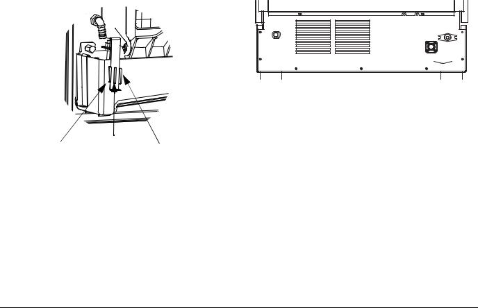
ICE THICKNESS ADJUSTMENT |
|
|
|
|
|
|
The ice thickness can be adjusted to three levels. |
|
|
|
|
||
1. Pull forward on the bottom of the bracket until clear |
WATER/DRAIN CONNECTIONS |
|||||
of the tab. |
|
|
|
A. Potable Water Inlet |
|
|
2. Slide the bracket over the desired tab and release. |
|
|
||||
|
B. Drain |
|
||||
• The center position is the normal factory setting. |
|
|
||||
|
C. Condenser Water Inlet - (Water-cooled Only) |
|||||
• To increase bridge thickness, raise the water level. |
|
|||||
|
D. Condenser Water Outlet - (Water-cooled Only) |
|||||
|
|
|
|
|||
•To decrease bridge thickness, lower the water level.
 C D
C D
A
B 


|
Thicker |
Factory |
Thinner |
|||
|
Default |
|||||
|
Bridge |
|
Setting |
Bridge |
|
|
|
|
|
|
|
|
|
Model |
|
|
|
Total ice weight from one cycle |
||
|
Minimum - Maximum |
Minimum - Maximum |
||||
|
|
|||||
U140 |
|
|
1.13 - 1.36 lbs |
513 |
- 617 grams |
|
U190 |
|
|
2.26 - 2.93 lbs |
1025 |
- 1329 grams |
|
U240 |
|
|
2.26 - 2.93 lbs |
1025 |
- 1329 grams |
|
U310 |
|
|
2.26 - 2.93 lbs |
1025 |
- 1329 grams |
|
Part Number 040002909 Rev02 4/15 |
11 |
Installation Instructions |
Section 2 |
|
|
Before Starting the Ice Machine
All Manitowoc ice machines are factory-operated and adjusted before shipment. Normally, new installations do not require any adjustment.
To ensure proper operation, follow the Operational Checks in Section 3 of this manual. Starting the ice machine and completing the Operational Checks are the responsibilities of the owner/operator.
Adjustments and maintenance procedures outlined in this manual are not covered by the warranty.
! Warning
Do not operate equipment that has been misused, abused, neglected, damaged, or altered/modified from that of original manufactured specifications.
Installation Checklist
Is the ice machine level?
Has all of the internal packing been removed?
Have all of the electrical and water connections been made?
Has the supply voltage been tested and checked against the rating on the nameplate?
Is there proper clearance around the ice machine for air circulation?
Is the ice machine grounded and polarity correct?
Has the ice machine been installed where ambient temperatures will remain in the range of 40° – 110°F (4° – 43°C)?
Has the ice machine been installed where the incoming water temperature will remain in the range of 40° – 90°F (4° – 32°C)?
Is there a separate drain for the water-cooled condenser?
Is the ice machine drain vented?
Are all electrical leads free from contact with refrigeration lines and moving equipment?
Has the owner/operator been instructed regarding maintenance and the use of Manitowoc Cleaner and Sanitizer?
Has the owner/operator completed the warranty registration card?
Has the ice machine and bin been sanitized?
Has the On/Off button been pressed?
Is there a separate drain for the bin?
12 |
Part Number 040002909 Rev02 4/15 |
Section 3
Operation
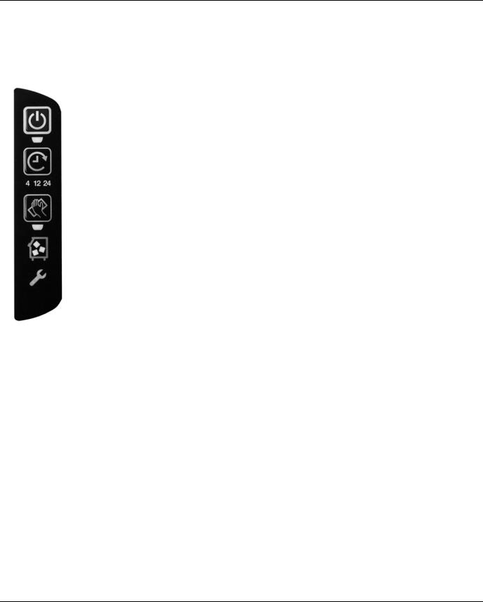
Touch Pad Features
The touch pad offers a series of pressure sensitive buttons to control ice machine operation and provide operational status.
On/Off - Blue = Machine On
Off = Machine Is Off
Delay - Blue = Delay Mode On
Off = Delay Mode Is Off
Clean - Yellow = Clean Cycle On
Flashing = Clean Cycle Paused
Off = Cleaning is Off
Bin Full - Blue = Bin Is Full
Off = Bin Is Not Full
Service - Red = Safety Limit
Off = Doesn’t Need Service
ON/OFF
The On/Off Button is used to start and stop ice making. The blue light indicates whether the ice machine is in Ice Making (light on) or Off (light off).
NOTE: If ice is on the evaporator (during the freeze or harvest cycle) and the On/Off button is pressed; the next cycle will have a thick slab of ice. Press the On/Off button and allow the ice to melt off the evaporator, then start a new freeze cycle.
DELAY
Pressing the Delay button will start a delay period. The ice machine will finish the freeze and harvest cycle and then start the delay period.
•Pressing the button once will start a 4 hour delay period.
•Pressing the button twice will start a 12 hour delay period.
•Pressing the button three times will start a 24 hour delay period.
•Pressing the button four times will cancel the delay periods.
NOTE: The delay period will be canceled if power is interrupted to the ice machine. When power is restored, the ice machine will remain Off.
CLEAN
Pressing the Clean button for 3 seconds with the machine off will start a clean cycle. After the clean cycle is complete, the ice machine will automatically start an ice making cycle.
•Pressing the Clean button ag ain within 45 seconds of the clean cycle starting will abort the clean cycle.
•Pressing the On/Off button anytime during the Clean cycle will de-energize the On/Off LED and the ice machine will stop after the Clean cycle is complete.
•Pressing the Clean button will pause the Clean cycle. The On/Off and Clean lights will flash on/off to indicate pause mode. Pressing the Clean button again will continue the Clean cycle from the point of interruption.
NOTE: Opening the ice damper for 30 seconds will cancel the clean cycle.
BIN FULL
The Bin Full light energizes when the bin is full or is deenergized if the bin is not full.
SERVICE
The service light indicates the machine needs attention.
•Refer to Section 5 for more information if this light is energized.
Part Number 040002909 Rev02 4/15 |
13 |

Operation |
Section 3 |
|
|
Ice Making Sequence of Operation
NOTE: The On/Off button must be depressed and the ice damper must be closed before the ice machine will start.
Water Purge Cycle
The ice machine purges any remaining water from the water trough down the drain.
Freeze Cycle
Prechill - The refrigeration system chills the evaporator before water flow over the evaporator starts. The water inlet valve energizes during the pre-chill and remains on until the ice thickness float switch is satisfied.
Freeze - Water flowing across the evaporator freezes and builds ice on the evaporator. After a sheet of ice has formed, the harvest float switch signals the control board to start a harvest cycle.
Harvest Cycle
Any remaining water is purged down the drain as refrigerant gas warms the evaporator. When the evaporator warms, the sheet of cubes slides off the evaporator and into the storage bin. If all cubes fall clear of the ice damper the ice machine starts another freeze cycle.
Full Bin Cycle
If the ice damper is held open by ice cubes the ice machine shuts off. When the ice damper closes the ice machine starts a new cycle at the water purge.
Control Board Timers
The control board has the following non-adjustable timers:
•The ice machine is locked into the freeze cycle for 6 minutes before a harvest cycle can be initiated.
•The maximum freeze time is 45 minutes at which time the control board automatically initiates a harvest sequence.
•The maximum harvest time is 7 minutes. The control board automatically initiates a freeze sequence when these times are exceeded.
SAFETY LIMITS
Safety limits are stored and indicated by the control board. The number of cycles required to stop the ice machine varies for each safety limit.
Safety limits can be reset by pressing the On/Off button and starting a new ice making cycle.
A safety limit is indicated by an energized Service Light on the touch pad. Refer to Section 5 if you receive a safety limit indication.
•Safety Limit 1 -If the freeze time reaches 45 minutes, the control board automatically initiates a harvest cycle. After 6 consecutive 45-minute freeze cycles occur, the ice machine stops.
•Safety Limit 2 - If the harvest time reaches 3.5 minutes, the control board automatically energizes the water pump and extends the harvest cycle another 3.5 minutes (7 minutes total). After 7 minutes the ice machine automatically starts a new freeze cycle. If 3 consecutive 7 minute harvest cycles occur, the ice machine stops.
•Safety Limit 3 - If the freeze time reaches 4 minutes and water is not sensed, the ice machine stops and initiates a 30 minute delay period. The ice machine will automatically restart at the end of the 30 minute delay period. If 100 consec utive failures occur the ice machine stops.
14 |
Part Number 040002909 Rev02 4/15 |
 Loading...