

Page 1
Owner’s Manual
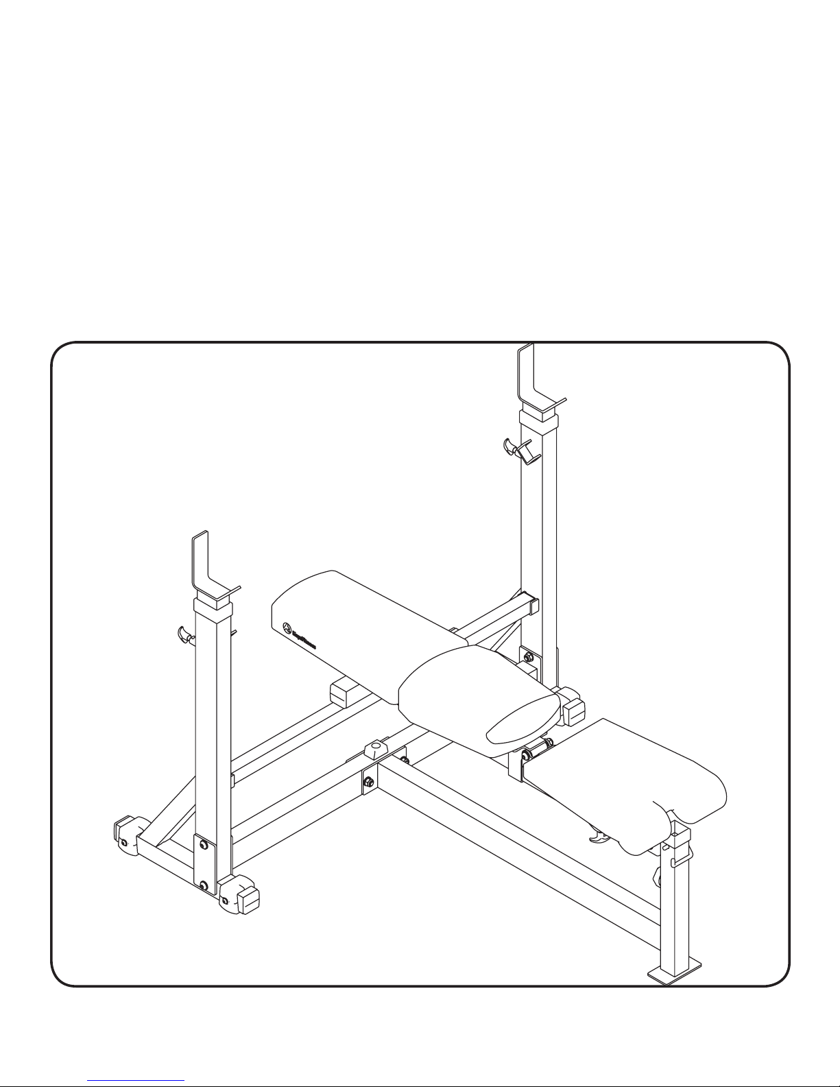
KF-OB
O
lympic
B
ench
215-00121
10/06 Rev A
Page 2

Table Of Contents
Before You Start 3
Important Safety Information 4
Assembly 5-10
Parts List 11
Exploded View 12
Warranty Information 13
2
Page 3

Before You Start
THANK YOU for making this unit a part of your exercise program.
Keys Fitness assures the very best in value, appearance, durability
and biomechanics.
This manual will guide you through the assembly process. If at any time you are
having trouble with the assembly or use of this product, then please contact us
at our Keys Fitness Help line. We have trained service technicians on site to take
care of you, our valued customer.
REGISTRATION CARD
To avoid unnecessary delays in warranty parts and to insure that a permanent
record of your purchase is on file with our company, be sure to send in the warranty registration card or register on-line at www.keysfitness.com within 10 days
of purchase.
3
Page 4

Important Safety Information
Prior to assembly, remove components from the box and verify that all the listed parts were
supplied.
NOTE
Read all precautions and instructions in this manual before using this equipment.
:
Hand tighten bolts and nylon nuts until machine is fully assembled.
WARNING!
Before using this unit or starting any exercise program, consult your
physician. This is especially important for persons over the age of
35 and/or persons with pre-existing health problems. Keys Fitness
Products LP assumes no responsibility for personal injury or property
damage sustained by or through the use of this product.
It is the owner’s responsibility to ensure that all users of this unit have
read the Owner’s Manual and are familiar with safety information and
precautions.
SAFETY PRECAUTIONS
• This unit should only be used on a level surface and is intended for
indoor use only. Keys Fitness recommends an equipment mat be
placed under the unit to protect the floor or carpet and for easier
cleaning.
• Wear comfortable, good-quality walking or running shoes and
appropriate clothing. Do not use this unit with bare feet, sandals,
socks or stockings!
• Always examine your unit before using to ensure all parts are in
working order.
• Do not leave children unsupervised near or on the unit.
• Service to your unit should only be performed by an authorized
service representative, unless authorized and/or instructed by a
Keys Fitness technician. Failure to follow these instructions will void
the warranty.
4
Page 5

Assembly
5
Page 6

Assembly
NOTE: Hand tighten bolts and nylon nuts until machine is fully assembled.
STEP 1
Connect Cross Frame (3) to Left and Right Uprights (1 and 2) using
Bolts (31), Washers (37), Square Plate (18) and Nylon Nuts (35).
Slide Support Bar (17) into holders in Left and Right Uprights.
Insert Adjustable Weight Supports (7) into Left and Right Uprights.
Secure with Short Pop Pins (16).
66
Page 7

Assembly
NOTE: Hand tighten bolts and nylon nuts until machine is fully assembled.
STEP 2
Connect Main Frame (4) to Cross Frame (3) using Bolts (31), Washers
(37) and Nylon Nuts (35).
Connect Guide Frame (5) to top of Main Frame (4) using Bolt (30),
Washers (37) and Nylon Nut (35).
77
Page 8

A
A
Assembly
NOTE: Hand tighten bolts and nylon nuts until machine is fully assembled.
STEP 3
CARRIAGE ASSEMBLY (A): Slide Adjustable Pin (11) down into
Carriage (8) and secure with Washer (37) and Nylon Nut (35).
Connect Spring (27) to Adjustable Pin (11) and Carriage (8).
Connect Decline Handle (6) to Guide Frame (5) using Bolt (32),
Washers (38) and Nylon Nut (36).
88
Page 9

B
B
Assembly
NOTE: Hand tighten bolts and nylon nuts until machine is fully assembled.
STEP 4
CARRIAGE ASSEMBLY (B): Connect Seat Support (10) to Carriage
(8) with Bolt (29), Washers (37) and Nylon Nut (35).
Connect Back Pad Support (9) to Carriage (8) with Bolt (29), Washers
(37) and Nylon Nut (35).
99
Page 10

Assembly
NOTE: Hand tighten bolts and nylon nuts until machine is fully assembled.
STEP 5
Connect Back Pad (12) to Back Pad Support (9) using Screws (34).
Connect Lower Back Pad (44) to Back Pad Support (9) using Screws (34).
Connect Seat Pad (13) to Seat Support (10) using Bolts (33) and Washers
(38).
Insert L Pin (28) and screw in Knob (15) into front of unit - both (28) and
(15) are used to secure attachments.
1010
Page 11

A
Parts List
KF-OB Parts List Rev
Ref # Part # Description Qty
1 223-00967 UPRIGHT, RIGHT KF-OB 1
2 223-00968 UPRIGHT, LEFT KF-OB 1
3 223-00970 CROSS FRAME, KF-OB 1
4 223-00969 MAIN FRAME, KF-OB 1
5 223-00971 GUIDE FRAME, KF-OB 1
6 219-00492 DECLINE HANDLE, KF-OB 1
7 223-00972 ADJUSTABLE WEIGHT SUPPORT, KF-OB 2
8 223-00973 CARRIAGE, KF-OB 1
9 223-00974 SUPPORT, BACK PAD KF-OB 1
10 223-00974 SUPPORT, BACK PAD KF-OB 1
11 210-00015 ADJ PIN FOR SEAT 1
12 228-00221 BACK PAD, UPPER KF-OB 1
13 228-00222 SEAT PAD, KF-OB 1
14 206-00467 BALL HEAD, KF-OB 1
15 210-00022 KNOB BOLT M12*25 1
16 210-00021 POP PIN 2
17 223-00975 SUPPORT BAR, KF-OB 1
18 219-00493 SQUARE PLATE, KF-OB 2
19 206-00103 LAT BAR GRIP - KPS 1
20 206-00392 FOOT CAP, RIGHT 50.8 KF SERIES 4
21 206-00035 PLASTIC SLEEVE, 63.5X50.8 2
22 206-00029 PLASTIC SLEEVE 50.8*76.2 2
23 206-00391 SQUARE PLUG, 50.8 KF SERIES 6
24 206-00023 END CAP KPS-OB 1
25 206-00182 PLUG 38 2
26 202-00023 BRONZE BUSHING, ID 12.2 6
27 202-00118 SPRING 1
28 210-00146 U PIN, KPS-HCL, KPS-LEGA, KPS-OB 1
29 202-00685 SCREW, BUTTON HD SOCKET CAP M12X90 2
30 202-00686 SCREW, BUTTON HD SOCKET CAP M12X85 1
31 202-00687 SCREW, BUTTON HD SOCKET CAP M12X80 6
32 202-00640 SCREW, M12X80 BUTTON HEAD SOCKET CAP 1
33 202-00665 SCREW, BUTTON HEAD SOCKET CAP M10X65 2
34 202-00688 SCREW, FLAT SOCKET HD M10X25 4
35 202-00092 NYLON NUT, M12 10
36 202-00091 NYLON NUT, M10 1
37 202-00222 WASHER, 13X26X2 KPSFI #32 19
38 202-00223 WASHER, 11X23X2 4
39 206-00114 PLASTIC SLEEVE, 50.8x44.5 1
40 210-00034 LONG POP PIN, KPS-OB/KPS-1800 1
41 202-00636 SCREW, M8X25 BUTTON HEAD SOCKET CAP 9
42 202-00224 WASHER, 9X16X1.6 9
43 206-00022 RUBBER BUMPER KPS-OB #43 1
44 228-00223 BACK PAD, LOWER KF-OB 1
45 206-00393 FOOT CAP, LEFT 50.8 KF SERIES 4
# 202-00689 BOLT PACK, KF-OB 1
1111
Page 12

Exploded View
1212
 Loading...