

Page 1

TABLE
OF
FLASHCODES
FOR FAULT MEMORIES
SD 206-2.97 e
Page 1 of 62
Page 2

Note:
For notes on setting and repair of individual systems please
consult the Repair Manuals or the relevant Service Information sheets.
Notes/additions
SD 206-2.97
Page 2 of
62
Page 3

Index
ABS/ASR
⇒ 2E Bosch.........................................................................Page 4 - 5
⇒ 3E Bosch.........................................................................Page 6 - 7
⇒ 2M Bosch........................................................................Page 8 - 9
⇒ 2M Stage 1 Bosch...........................................................Page10 - 11
⇒ CI 12 Bosch....................................................................Page12 - 15
⇒ Knorr...............................................................................Page16 - 17
⇒ Wabco "C".......................................................................Page18 - 21
Running gear:
⇒ ECAS, buses...................................................................Page22 - 24
⇒ ECAS, trucks...................................................................Page26 - 27
⇒ EFR running gear control, trucks.....................................Page28 - 30
Gearboxes:
⇒ Automated pre-selector shift (AVS).................................Page40 - 41
⇒ Renk Doromat.................................................................Page42 - 43
⇒ SAMT B...........................................................................Page44 - 45
⇒ Voith-Diwa 3....................................................................Page46 - 47
⇒ Voith retarder..................................................................Page48 - 49
⇒ ZF HP 500.......................................................................Page52 - 54
⇒ ZF retarder (Intarder).......................................................Page50 - 51
Heating/air-conditioning
⇒ D1LCC/D3LCC, Eberspächer..........................................Page32 - 33
⇒ Heater controls, Dreiha....................................................Page34 - 35
⇒ Air-conditioner, Behr........................................................Page36 - 37
⇒ Heater/air-conditioner control, Wabco (ATC)...................Page38 - 39
⇒ Airtop 2000, Webasto......................................................Page 31
Engine:
⇒ EDC M7..........................................................................Page56 - 57
⇒ EDC MS5........................................................................Page58 - 59
⇒ EMS 3.3..........................................................................Page 55
⇒ Speed limiter VDO AGB-S..............................................Page60 - 61
⇒ Air injection, Wabco........................................................Page 62
Door control, IFE..................................................................Page 25
SD 206-2.97
Page 3 of
62
Page 4
BOSCH ABS/ASR 2E
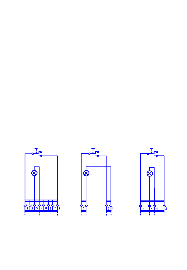
Reading out the fault memory
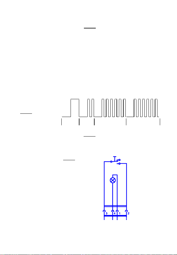
− Switch off ignition and connect up request button
− Switch on ignition and press button for more than 1 second
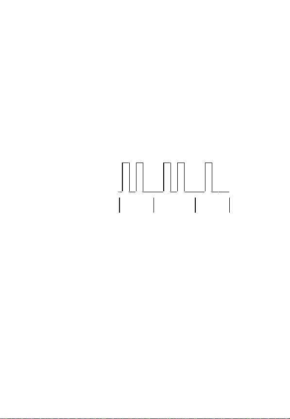
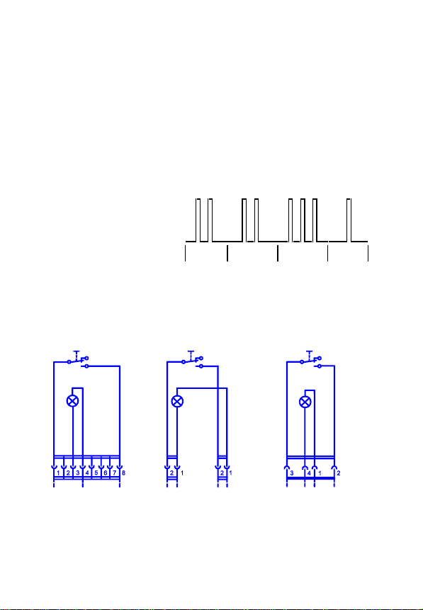
The fault codes are emitted in three blocks. The first block indicates which control unit
status (configuration) is set. In the second and third blocks the faults in the diagonals FL/RR
(second block) and FR/RL (third block) can be read out.
Pause between flashes............................................................ approx. 0.5 s
Duration of flashes................................................................... approx. 0.5 s
Pause between individual blocks............................................. approx. 1.5 s
Example of flashcode: Flashcode 2 in Block 1 for an ABS unit,
flashcode 2 in Block 2 and flashcode 1 in
Block 3.
Lamp in
request
button
Erasing the fault memory
− Switch off ignition and connect up request button
− Press button and keep it pressed
− Switch on ignition and release button after > 3 seconds
on
off
Block 1 Block 2 Block 3
SD 206-2.97
Page 4 of
62
Page 5
Block 1: Flashcode
ABS unit................................................................................................................2
ABS unit with ASR engine control (not an MAN application))................................3
ABS unit with ASR brake control (not an MAN application)...................................4
ABS unit with ASR brake and engine control....................................................5
Flashcodes 3 and 4 may be emitted if components are not connected up or are defective.
Block 2 (FL/RR) and Block 3 (FR/RL):
Fault type Flashcode
No fault...................................................................................................................1
Control unit defective .............................................................................................2
Speed sensor signal path:
⇒ front: inadmissible gap ......................................................................................3
⇒ rear: inadmissible gap.......................................................................................4
⇒ front: crack or short-circuit.................................................................................6
⇒ rear: crack or short-circuit..................................................................................7
Undervoltage, or relay for pressure control valve cannot be triggered ..................9
Pressure control valve signal path:
⇒ front.................................................................................................................10
⇒ rear ..................................................................................................................11
Relay for pressure control valve cannot switch (sticking))...................................13
Signal path for ASR solenoid valve......................................................................14
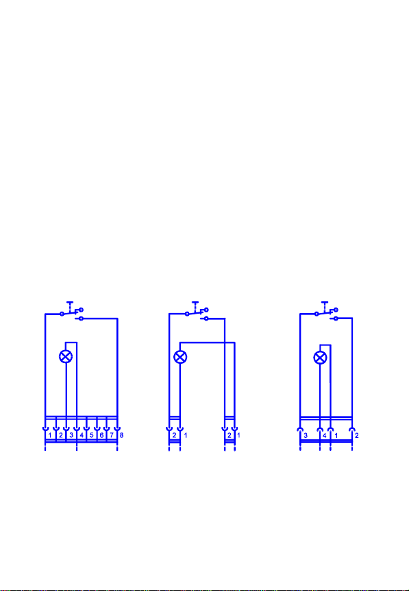
Connection diagram for request button
X124
X202X202X201Bus X40
SD 206-2.97
Page 5 of
62
Page 6
BOSCH ABS/ASR 3E
Reading out the fault memory
− Switch off ignition and connect up request button
− Switch on ignition
− Press button for > 2 seconds
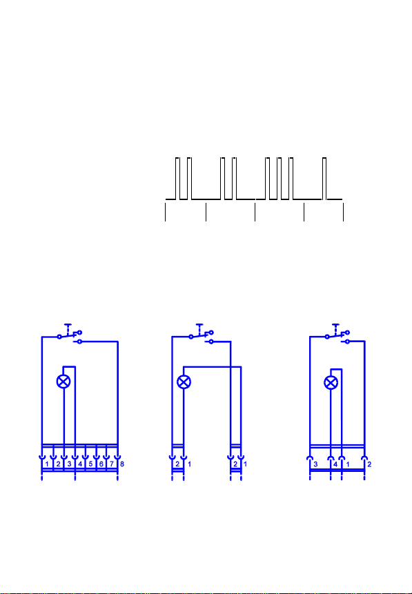
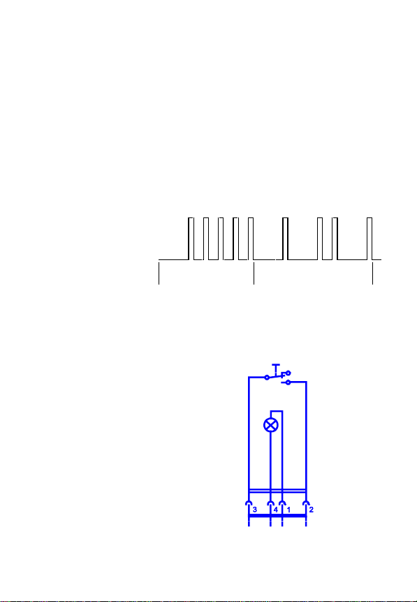
Blocks 1 and 2 indicate the configuration of the control unit. In Blocks 3 and 4 the faults in
the diagonals FL/CR/RL (Block 3) and FR/CL/RR (Block 4) can be read out.
Example of flashcode: Flashcode 2 in Block 1, Flashcode 2 in Block 2, Flashcode 3 in
Block 3 and Flashcode 1 in Block 4.
Lamp in
request
button
Erasing the fault memory
− Switch off ignition and connect up request button
− Press button and keep it pressed
− Switch on ignition and release button after > 3 seconds
Connection diagram for request button
on
off
Block 1 Block 2 Block 3 Block 4
SD 206-2.97
Page 6 of
62
X124
X202X202X201Bus X40
Page 7

Block 1: Flashcode
ABS unit............................................................................................................................2
ABS unit with ASR engine control (not an MAN application).............................................3
ABS unit with ASR brake control at rear (not an MAN application)....................................4
ABS unit with ASR brake control at rear and engine control......................................5
ABS unit with ASR brake control in centre (not an MAN application)................................6
ABS unit with ASR brake control in centre and engine control
(not an MAN application)....................................................................................................7
ABS unit with ASR brake control at rear and in centre
(not an MAN application)....................................................................................................8
ABS unit with ASR brake control at rear and in centre and engine control
(not an MAN application)....................................................................................................9
Flashcodes 3, 4, 6, 7, 8 and 9 may occur if components are defective or not connected up.
Block 2: Flashcode
24 V operation, modified individual control on front axle ...................................................2
Block 3 (FL/CR/RL) and Block 4 (FR/CL/RR):
Type of fault Flashcode
No fault...............................................................................................................................1
Control unit defective .........................................................................................................2
Speed sensor signal path:
⇒ front: inadmissible gap ..................................................................................................3
⇒ centre: inadmissible gap................................................................................................4
⇒ rear: inadmissible gap...................................................................................................5
⇒ front: crack or short-circuit.............................................................................................6
⇒ centre: crack or short-circuit..........................................................................................7
⇒ rear: crack or short-circuit..............................................................................................8
Undervoltage, or relay for pressure control valves cannot be triggered.............................9
Signal path for pressure control valve:
⇒ front.............................................................................................................................10
⇒ centre...........................................................................................................................11
⇒ rear ..............................................................................................................................12
Relay for pressure control valve cannot switch (sticking) ................................................13
Signal path for ASR solenoid valve..................................................................................14
Inadmissible configuration (incorrect solenoid valve may be fitted).................................15
SD 206-2.97
Page 7 of
62
Page 8
BOSCH ABS/ASR 2M
Reading out the fault memory
− Switch off ignition and connect up request button
− Switch on ignition
− Press button for > 1 second
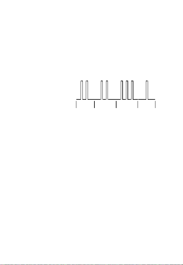
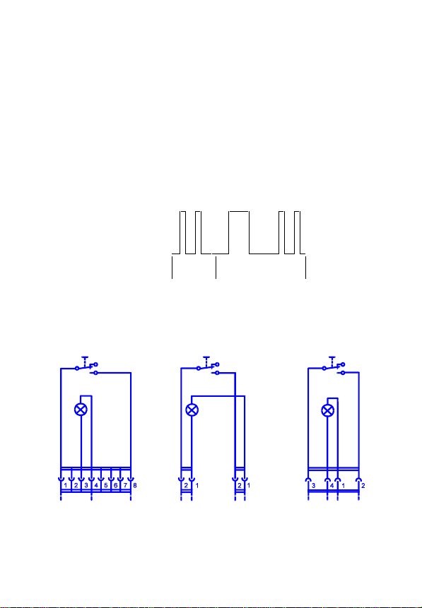
Blocks 1 and 2 indicate the configuration to which the control unit is set. In Blocks 3 and 4
the faults in the diagonals FL/RR (Block 3) and FR/RL (Block 4) can be read out.
Duration of a flash.................................................................... approx. 0,2 s
Pause between flashes............................................................ approx. 0,4 s
Pause between blocks............................................................. approx. 1,5 s
Example of flashcode: Flashcode 2 in Block 1, Flashcode 2 in Block 2,
Lamp in
request
button
Erasing the fault memory
− Switch off ignition and connect up request button
− Press button and keep it pressed
− Switch on ignition and release button after > 2 seconds
ASR check lamp: Continually on: fault in servomotor path
Gap recognition from control unit 81.25935-6410 onwards
− Drive vehicle at speed > 20 km/h
− Stop vehicle and switch off ignition
− Switch on ignition
⇒ Gap in order: ABS lamp continually on.
⇒ Gap enlarged: ABS lamp flashes 3 x and then remains continually on.
Adjust speed sensors and accelerate vehicle several times from standstill
to > 20 km/h so that the control unit can adjust to the change in the gaps.
Flashcode 3 in Block 3 and Flashcode 1 in Block 4.
on
off
Block 1 Block 2 Block 3 Block 4
Dimmed permanent light: fault in signal at terminal W
SD 206-2.97
Page 8 of
62
Page 9
Block 1: Flashcode
ABS unit with HGB (from control unit 81.25935-6410)......................................2
ABS unit with ASR engine control and HGB (not an MAN application)..................3
ABS unit with ASR brake control (not an MAN application)...................................4
ABS unit with ASR brake and engine control and HGB...................................5
Flashcodes 3 and 4 may occur if components are defected or not connected up.
Block 2: Flashcode
24 V operation: individual control modified on front axle .......................................2
Block 3 (FL/RR) and Block 4 (FR/RL):
Type of fault Flashcode
No fault...................................................................................................................1
Control unit defective .............................................................................................2
Speed sensor signal path:
⇒ front: inadmissible gap or short-circuit...............................................................3
⇒ rear: inadmissible gap or short-circuit...............................................................4
⇒ front: crack or short-circuit.................................................................................5
⇒ rear: crack or short-circuit..................................................................................6
Undervoltage or relay for pressure control valve cannot be triggered ...................7
Pressure control valve signal path:
⇒ front...................................................................................................................9
⇒ rear ..................................................................................................................10
Relay for pressure control valve cannot switch (sticking) ....................................13
Signal path for ASR solenoid valve......................................................................14
Connection diagram for request button
Bus X40
X124
X201
X202X202
SD 206-2.97
Page 9 of
62
Page 10
BOSCH ABS/ASR 2M Stage 1
Reading out the fault memory
− Switch off ignition and connect up request button
− Switch on ignition
− Press button for > 1 second
Blocks 1 and 2 indicate the configuration to which the control unit is set. In Blocks 3 and 4
the faults in the diagonals FL/RR (Block 3) and FR/RL (Block 4) can be read out.
Duration of a flash............................................................................................approx. 0.2 s
Pause between flashes....................................................................................approx. 0.4 s
Pause between blocks.....................................................................................approx. 1.5 s
Example of flashcode: Flashcode 2 in Block 1, Flashcode 2 in Block 2,
Lamp in
request
button
Erasing the fault memory
− Switch off ignition and connect up request button
− Press button and keep it pressed
− Switch on ignition and release button after > 3 seconds
Connection diagram for request button
Flashcode 3 in Block 3 and Flashcode 1 in Block 4.
on
off
Block 1 Block 2 Block 3 Block 4
Bus X40 X201 X202 X202
SD 206-2.97
Page 10 of
62
Page 11

Block 1: Flashcode
ABS unit with HGB...............................................................................................................2
ABS unit with ASR engine control and HGB (not an MAN application)..................................3
ABS unit with ASR brake control and HGB (not an MAN application)...................................4
ABS unit with ASR brake and engine control and HGB...................................................5
Flashcodes 3 and 4 may occur if components are defective or not connected up.
Block 2: Flashcode
24 V operation: individual control modified on front axle .......................................................2
Block 3 (FL/RR) and Block 4 (FR/RL):
Type of fault Flashcode
No fault...................................................................................................................................1
Control unit defective .............................................................................................................2
Speed sensor signal path:
⇒ front: inadmissible gap or short-circuit...............................................................................3
⇒ rear: inadmissible gap or short-circuit...............................................................................4
⇒ front: crack or short-circuit.................................................................................................6
⇒ rear: crack or short-circuit..................................................................................................7
Undervoltage or relay for pressure control valves cannot be triggered..................................9
Pressure control valve signal path:
⇒ front.................................................................................................................................10
⇒ rear ..................................................................................................................................11
Relay for pressure control valve cannot switch (sticking) ....................................................13
Signal path for ASR control valve ........................................................................................14
Fault in servomotor ..............................................................................................................15
Fault in C3/B7-Signal...........................................................................................................16
Fault in signal at terminal W ................................................................................................17
Wheel equalisation difference too large...............................................................................18
Fault in signal path for relay for engine brake/retarder switch-off
(emission possible only in Block 4)......................................................................................19
Fault in signal path for clutch switch ....................................................................................20
Gap recognition
− Drive vehicle at > 20 km/h
− Stop vehicle and switch off ignition
− Switch on ignition
⇒ Gap in order: ABS lamp is continually on.
⇒ Gap enlarged: ABS lamp flashes 3x and then remains continually on.
Adjust speed sensors and accelerate vehicle several times from standstill to > 20 km/h
so that the control unit can adjust to the changed gaps.
SD 206-2.97
Page 11 of
62
Page 12
BOSCH ABS/ASR CI 12
Reading out the fault memory
− Switch off ignition and connect up request button
− Switch on ignition
− Wait for 2 seconds and then press button for at least 2 seconds.
The flashcodes are emitted in two blocks. Block 1 indicates the configuration to which the
control unit is set. Block 2 indicates the actual fault code. Each fault code must be requested individually.
Pause before first flash ....................................................................................approx. 3 s
Duration of a flash............................................................................................approx. 0.5 s
Pause between hundreds and tens or tens and units.......................................approx. 3 s
Pause between hundreds and hundreds..........................................................approx. 1 s
Pause between tens and tens..........................................................................approx. 1 s
Pause between units and units.........................................................................approx. 1 s
Example of flashcode: Flashcode 5 in Block 1, Flashcode 121 in Block 2.
Lamp in
request
button
Erasing the fault memory
− Switch off ignition and connect up request button
− Press the button
− Switch on ignition and keep button pressed for > 2 seconds
− Do not switch off ignition until at least 5 seconds have passed.
Connection diagram for request button
on
off
Block 1 Block 2
SD 206-2.97
Page 12 of
X202
62
Page 13

Block 1: Flashcode
Pure ABS unit, modified individual control on front axle.................................................2
ABS unit with ASR engine control (not an MAN application).................................................3
ABS unit with ASR brake control (not an MAN application)...................................................4
ABS unit with ASR brake and engine control....................................................................5
Pure ABS unit with Select-Low control on front axle
(not an MAN application)........................................................................................................6
ABS unit with Select-Low control on front axle and
ASR engine control (not an MAN application)........................................................................7
ABS unit with Select-Low control on front axle and
ASR brake control (not an MAN application) .........................................................................8
ABS unit with Select-Low control on front axle and
ASR brake and engine control (not an MAN application).......................................................9
Flashcodes 3, 4, 6, 7, 8 and 9 may occur if components are defective or not connected up.
Block 2:
Type of fault Flashcode
No fault...............................................................................................................................121
CAN data bus:
⇒ BusOff, repair CAN bus.................................................................................................211
⇒ Tachograph signal, plausibility......................................................................................212
⇒ Communication interrupted, repair CAN bus.................................................................213
⇒ Time-out, gearbox messages, repair CAN bus .............................................................214
⇒ Time-out, engine messages, repair CAN bus................................................................215
⇒ Time-out, retarder messages, repair CAN bus..............................................................216
Brake light switch not yet actuated, check cabling.............................................................217
Control unit defective .........................................................................................................221
Control unit defective .........................................................................................................222
Control unit defective .........................................................................................................223
Control unit defective .........................................................................................................224
Control unit defective .........................................................................................................225
Control unit defective .........................................................................................................226
Control unit defective .........................................................................................................227
Configuration EEPROM parameters defective...................................................................228
Axle tyres or pulse ring incorrect........................................................................................232
Voltage supply to pressure control valve, undervoltage.....................................................242
Voltage supply to pressure control valve, interruption .......................................................243
Control unit defective .........................................................................................................244
Pressure control valve:
⇒ Earth, FR or RL, control unit output, short-circuit to earth.............................................251
⇒ Earth, FR or RL, control unit output, short-circuit to +UBatt..........................................252
⇒ Earth, diagonal FR/RL, interruption (PIN X1, 12)..........................................................253
⇒ Voltage supply, diagonal FR/RL, incorrect polarity of +/-..............................................254
⇒ Earth, FL or RR, control unit output, short-circuit to earth.............................................255
⇒ Earth, FL or RR, control unit output, short-circuit to +UBatt..........................................256
SD 206-2.97
Page 13 of
62
Page 14

Pressure control valve:
⇒ Earth, diagonal FL/RR, interruption (PIN X1, 11)..........................................................257
⇒ Voltage supply, diagonal FL/RR, incorrect polarity of +/-..............................................258
Speed sensors:
⇒ RL, interruption/short-circuit ..........................................................................................312
⇒ RL, pulse ring defective, gap too large..........................................................................316
⇒ FL, interruption/short-circuit...........................................................................................322
⇒ FL, pulse ring defective, gap too large ..........................................................................326
⇒ RR, interruption/short-circuit..........................................................................................342
⇒ RR, pulse ring defective, gap too large .........................................................................346
⇒ FR, interruption/short-circuit..........................................................................................362
⇒ FR, pulse ring defective, gap too large..........................................................................366
⇒ RL, interturn fault, gap, pole wheel, signal ....................................................................411
⇒ RL, tyres or pulse ring incorrect ....................................................................................415
⇒ FL, interturn fault, gap, pole wheel, signal.....................................................................421
⇒ FL, tyres or pulse ring incorrect.....................................................................................425
Speed sensors:
⇒ RR, interturn fault, gap, pole wheel, signal....................................................................441
⇒ RR, tyres or pulse ring incorrect....................................................................................445
⇒ FR, interturn fault, gap, pole wheel, signal....................................................................461
⇒ FR, tyres or pulse ring incorrect ....................................................................................465
Pressure control valve:
⇒ FL, inlet valve, interruption............................................................................................512
⇒ FL, inlet valve, short-circuit to earth ..............................................................................513
⇒ FL, inlet valve, short-circuit to +UBatt ...........................................................................514
⇒ FL, earth connection, interruption..................................................................................515
⇒ FL, outlet valve, interruption..........................................................................................516
⇒ FL, outlet valve, short-circuit to earth ............................................................................517
⇒ FL, outlet valve, short-circuit to +UBatt .........................................................................518
⇒ RL, inlet valve, interruption............................................................................................522
⇒ RL, inlet valve, short-circuit to earth..............................................................................523
⇒ RL, inlet valve, short-circuit to +UBatt ...........................................................................524
⇒ RL, earth connection, interruption..................................................................................525
⇒ RL, outlet valve, interruption..........................................................................................526
⇒ RL, outlet valve, short-circuit to earth............................................................................527
⇒ RL, outlet valve, short-circuit to +UBatt.........................................................................528
⇒ RR, inlet valve, interruption...........................................................................................532
⇒ RR, inlet valve, short-circuit to earth .............................................................................533
⇒ RR, inlet valve, short-circuit to +UBatt ..........................................................................534
⇒ RR, earth connection, interruption.................................................................................535
⇒ RR, outlet valve, interruption.........................................................................................536
⇒ RR, outlet valve, short-circuit to earth ...........................................................................537
⇒ RR, outlet valve, short-circuit to +UBatt ........................................................................538
⇒ FR, inlet valve, interruption............................................................................................552
SD 206-2.97
Page 14 of
62
Page 15

Block 2:
Type of fault Flashcode
Pressure control valve:
⇒ FR, inlet valve, short-circuit to earth..............................................................................553
⇒ FR, inlet valve, short-circuit to +UBatt...........................................................................554
⇒ FR, earth connection, interruption.................................................................................555
⇒ FR, outlet valve, interruption .........................................................................................556
⇒ FR, outlet valve, short-circuit to earth............................................................................557
⇒ FR, outlet valve, short-circuit to +UBatt.........................................................................558
⇒ FL, short-circuit to another valve...................................................................................611
⇒ FL, incorrectly configured..............................................................................................616
⇒ RL, short-circuit to another valve...................................................................................621
⇒ RR, short-circuit to another valve..................................................................................631
⇒ FR, short-circuit to another valve...................................................................................651
⇒ FR, incorrectly configured .............................................................................................656
ASR solenoid valve:
⇒ Interruption....................................................................................................................712
⇒ Short-circuit to earth......................................................................................................713
⇒ Short-circuit to +UBatt ...................................................................................................714
⇒ Short-circuit to another valve.........................................................................................721
⇒ Recognised but not configured......................................................................................726
Interaxle lock/shut-off valve, short-circuit to earth..............................................................811
Interaxle lock/shut-off valve, short-circuit to +UBatt...........................................................812
Engine interface:
⇒ DKR, short-circuit to earth or +UBatt.............................................................................813
⇒ DKV, actuator reports fault............................................................................................814
⇒ DKV, interruption/short-circuit........................................................................................815
⇒ DKV, time-out................................................................................................................816
Triggering of relay for engine brake/retarder:
⇒ Short-circuit to +UBatt ...................................................................................................817
⇒ Interruption or short-circuit to earth ...............................................................................818
SD 206-2.97
Page 15 of
62
Page 16
KNORR ABS
Reading out the fault memory
− Switch off ignition and connect up request button
− Switch on ignition and wait for 2 seconds
− Press button for 2 seconds
The first block indicates the configuration to which the control unit is set. The second block
indicates the fault codes. Each fault code must be requested individually.
Duration of a ten...............................................................................................approx. 2 s
Duration of a unit..............................................................................................approx. 0.5 s
Pause between tens and units .........................................................................approx. 3 s
Pause between units and units.........................................................................approx. 1 s
Pause between tens and tens..........................................................................approx. 1 s
Example of flashcode: Flashcode 2 in Block 1 and Flashcode 12 in Block 2.
Lamp in
request
button
Erasing the fault memory
− Switch of ignition and connect up request button
− Press button and keep it pressed
− Switch on ignition and release it after > 2 seconds
Connection diagram for request button
X124 X201 X202 X202
on
off
Block 1 Block 2
SD 206-2.97
Page 16 of
62
Page 17

Block 1: Flashcode
ABS unit without ASR..........................................................................................................2
ABS unit with ASR engine control (not an MAN application).................................................3
ABS unit with ASR brake control (not an MAN application)...................................................4
ABS unit with ASR brake and engine control (not an MAN application)................................5
Flashcodes 3, 4 and 5 may occur if components are defective or not connected up.
Block 2 (Diagonal 1 FR/RL, Diagonal 2 FL/RR):
Type of fault Flashcode
No fault...................................................................................................................................1
Speed sensors:
⇒ FL, interruption or short-circuit.........................................................................................10
⇒ FL, gap too large, interturn fault, pole wheel fault...........................................................11
⇒ FR, interruption or short-circuit........................................................................................12
⇒ FR, gap too large, interturn fault, pole wheel fault...........................................................13
⇒ RL, interruption or short-circuit........................................................................................14
⇒ RL, gap too large, interturn fault, pole wheel fault...........................................................15
⇒ RR, interruption or short-circuit........................................................................................16
⇒ RR, gap too large, interturn fault, pole wheel fault...........................................................17
Pressure control valve:
⇒ FL, interruption or short-circuit.........................................................................................22
⇒ FR, interruption or short-circuit........................................................................................23
⇒ RL, interruption or short-circuit........................................................................................24
⇒ RR, interruption or short-circuit........................................................................................25
ASR brake valve, RL, interruption or short-circuit................................................................28
ASR brake valve, RR, interruption or short-circuit...............................................................29
ASR engine control, E-Gas/EDC interface fault...................................................................31
Relay voltage supply for pressure control valve:
⇒ Diagonal 1 cannot be switched off (contact sticking).......................................................32
⇒ Diagonal 1 cannot be switched off...................................................................................33
⇒ Diagonal 2 cannot be switched off (contact sticking).......................................................34
⇒ Diagonal 2 cannot be switched off...................................................................................35
ABS engine brake/retarder switch-off, interruption or short-circuit.......................................36
ABS warning lamp, tractor, interruption or short-circuit........................................................38
Switch-on time monitoring of valves (implausible triggering)...............................................52
ASR recognised but not configured......................................................................................53
Differences in wheel diameter too large...............................................................................54
Voltage supply for pressure-control valves, diagonal 1, overvoltage...................................56
Voltage supply for pressure-control valves, diagonal 2, overvoltage...................................57
Speed recording, signals with frequency > 1500 Hz, unwanted signals..............................91
Pressure control valves, bleeding and holding times too long.............................................92
Configuration error (defective EEPROM parameters)..........................................................98
Control unit defective...........................................................................................................99
SD 206-2.97
Page 17 of
62
Page 18
WABCO „C“ ABS/ASR
Reading out the fault memory
− Switch-off ignition and connect up request switch
− Switch on ignition and wait for 2 seconds
− Close the switch
If the switch is opened the fault entry in the fault memory will be erased. Switching off the
ignition before the switch is opened ends the flashcode emission without erasing the fault in
the fault memory. The first block is a "starting block"; this begins the fault code emission.
The second block indicates the configuration to which the control unit is set. Blocks 3 and 4
indicate the actual fault codes. The flashcode emission may be deactivated (ended) only in
the pauses between the constantly repeated flashcodes.
Duration of starting block .................................................................................approx. 2.5 s
Pause between blocks.....................................................................................approx. 2.5 s
Duration of a flash............................................................................................approx. 0.5 s
Pause between flashes....................................................................................approx. 0,5 s
Example of flashcode: Starting block (Block1), Flashcode 2 in Block 2,
Lamp in
request
switch
Erasing the fault memory
− Switch off ignition and connect up request switch
− Switch on ignition and wait for 2 seconds
− Close the switch
− Open the switch during flashcode emission.
Connection diagram for request switch
Flashcode 6 in Block 3 and Flashcode 6 in Block 4.
on
off
Block 1 Block 2 Block 3 Block 4
SD 206-2.97
Page 18 of
X202
62
Page 19

Block 2:
ABS system 6S/6K.................................................................................................................1
ABS system 4S/4K.................................................................................................................2
ABS system 4S/3K.................................................................................................................3
ABS system 6S/4K.................................................................................................................4
ABS system 6S/3K.................................................................................................................5
Flashcodes 3, 4 and 5 may occur if parts are defective or not connected up.
Block 3 and Block 4:
Type of fault Flashcode
Valve relay FR/RL, undervoltage...........................................................................6 .............6
Valve relay FL/RR, undervoltage...........................................................................6 .............7
Speed sensor:
⇒ FR, wheel speed signal fault (failure)................................................................6 .............8
⇒ FL, wheel speed signal fault (failure).................................................................6 .............9
⇒ FR, interruption or short-circuit in cable ............................................................6 ...........10
⇒ FL, interruption or short-circuit in cable.............................................................6 ...........11
⇒ FR, wheel speed signal implausible..................................................................6 ...........12
⇒ FL, wheel speed signal implausible ..................................................................6 ...........13
⇒ RL, wheel speed signal fault (failure)................................................................7 .............0
⇒ RR, wheel speed signal fault (failure)................................................................7 .............1
⇒ RL, interruption of short-circuit in cable.............................................................7.............2
⇒ RR, interruption or short-circuit in cable............................................................7 .............3
⇒ RL, wheel speed signal implausible..................................................................7 .............4
⇒ RR, wheel speed signal implausible .................................................................7 .............5
⇒ ML, wheel speed signal fault (failure)................................................................7.............8
⇒ MR, wheel speed signal fault (failure)...............................................................7 .............9
⇒ ML, inadmissible impedance, interruption/short-circuit.....................................7 ...........10
⇒ MR, interruption or short-circuit in cable............................................................7 ...........11
⇒ ML, wheel speed signal implausible..................................................................7...........12
⇒ MR, wheel speed signal implausible.................................................................7 ...........13
Control unit defective .............................................................................................8 .............0
Control unit defective .............................................................................................8 .............1
ASR proportional valve (not an MAN application)..................................................8 .............2
ASR interface, DKR signal, interruption in cable (PIN 29).....................................8 .............3
ASR proportional valve (not an MAN application)..................................................8 .............4
ASR interface, DKV signal, faulty data transfer (PIN 28).......................................8 .............5
Interface for V signal (not an MAN application)......................................................8 .............6
ASR interface, DKV signal, interruption in cable (PIN 28) .....................................8 .............7
ASR interface, DKV signal, faulty data transfer (PIN 28).......................................8 .............9
Flashcode
Block 3 Block 4
SD 206-2.97
Page 19 of
62
Page 20

Type of fault Flashcode
Pressure control valve:
⇒ FR, inlet, short-circuit to earth ...........................................................................8 ...........10
⇒ FL, inlet, short-circuit to earth............................................................................8...........11
⇒ FR, inlet, interruption in cable............................................................................8 ...........12
⇒ FL, inlet, interruption in cable ............................................................................8 ...........13
⇒ FR, outlet, short-circuit to earth.........................................................................8 ...........14
⇒ FL, outlet, short-circuit to earth..........................................................................8 ...........15
⇒ FR, outlet, interruption in cable .........................................................................9 .............0
⇒ FL, outlet, interruption in cable..........................................................................9 .............1
⇒ RL, inlet, short-circuit to earth ...........................................................................9 .............2
⇒ RR, inlet, short-circuit to earth...........................................................................9.............3
⇒ RL, inlet, interruption in cable............................................................................9.............4
⇒ RR, inlet, interruption in cable ...........................................................................9 .............5
⇒ RL, outlet, short-circuit to earth .........................................................................9 .............6
⇒ RR, outlet, short-circuit to earth.........................................................................9 .............7
⇒ RL, outlet, interruption in cable..........................................................................9 .............8
⇒ RR, outlet, interruption in cable.........................................................................9 .............9
⇒ ML, inlet, short-circuit to earth...........................................................................9 ...........10
⇒ MR, inlet, short-circuit to earth ..........................................................................9 ...........11
⇒ ML, inlet, interruption in cable ...........................................................................9 ...........12
⇒ MR, inlet, interruption in cable...........................................................................9...........13
⇒ ML, outlet, short-circuit to earth.........................................................................9...........14
⇒ MR, outlet, short-circuit to earth ........................................................................9 ...........15
⇒ ML, outlet, interruption in cable .......................................................................10 .............0
⇒ MR, outlet, interruption in cable.......................................................................10 .............1
ASR valve RL, short-circuit to earth.....................................................................10 .............2
ASR valve RR, short-circuit to earth ....................................................................10 .............3
ASR valve RL, interruption in cable .....................................................................10 .............4
ASR valve RR, interruption in cable.....................................................................10 .............5
Retarder shut-off relay (PIN 11), short-circuit to +UBatt ......................................10 .............7
ASR engine control: inadmissible drive slip (EMS/EDC) .....................................10 .............8
ASR engine control: inadmissible drive slip (EMS/EDC) .....................................10 .............9
Pressure control valve:
⇒ FR, short-circuit to +UBatt or output stage defective.......................................11 ...........12
⇒ FL, short-circuit to +UBatt or output stage defective .......................................11 ...........13
⇒ RL, short-circuit to +UBatt or output stage defective.......................................11 ...........14
⇒ RR, short-circuit to +UBatt or output stage defective ......................................11 ...........15
⇒ ML, short-circuit to +UBatt or output stage defective ......................................12.............0
⇒ MR, short-circuit to +UBatt or output stage defective......................................12 .............1
ASR valve RL, short-circuit to +UBatt or output stage defective..........................12 .............2
ASR valve RR, short-circuit to +UBatt or output stage defective.........................12 .............3
ASR proportional valve (not an MAN application)................................................12 .............4
Retarder shut-off relay (PIN 11), short-circuit to earth.........................................12 .............7
Block 3 Block 4
SD 206-2.97
Page 20 of
62
Page 21

Type of fault Flashcode
Pressure control valve:
⇒ FR, short-circuit to +UBatt...............................................................................12 .............8
⇒ FL, short-circuit to +UBatt................................................................................12 .............9
⇒ RL, short-circuit to +UBatt ...............................................................................12 ...........10
⇒ RR, short-circuit to +UBatt...............................................................................12 ...........11
⇒ ML, short-circuit to +UBatt...............................................................................12 ...........12
⇒ MR, short-circuit to +UBatt ..............................................................................12 ...........13
ASR valve RL, short-circuit to +UBatt..................................................................12 ...........14
ASR valve RR, short-circuit to +UBatt .................................................................12 ...........15
ASR proportional valve (not an MAN application)................................................13 .............0
Valve relay RL/FR, relay contact sticking ............................................................13 .............4
Valve relay RR/FL, relay contact sticking ............................................................13 .............5
Control unit defective ...........................................................................................13 .............6
Control unit overvoltage, check alternator charge voltage...................................13 .............7
Control unit defective ...........................................................................................13 .............8
Control unit defective ...........................................................................................13 .............9
Control unit defective ...........................................................................................13 ...........10
Control unit defective ...........................................................................................13 ...........11
Control unit defective ...........................................................................................13 ...........12
Control unit defective ...........................................................................................13 ...........13
Control unit defective ...........................................................................................13 ...........14
Control unit defective ...........................................................................................13 ...........15
Control unit defective ...........................................................................................14 .............0
Control unit defective ...........................................................................................14 .............1
Control unit defective ...........................................................................................14 .............2
Control unit defective ...........................................................................................14 .............3
Control unit defective ...........................................................................................14 .............4
Control unit defective ...........................................................................................14 .............5
Pressure control valve modulation RL/FR, switch-on time too long.....................14 .............6
Pressure control valve modulation RR/FL, switch-on time too long.....................14 .............7
ASR valve RL, switch-on time too long................................................................14 .............8
ASR-valve RR, switch-on time too long...............................................................14 .............9
Control unit defective ...........................................................................................14 ...........10
Control unit defective ...........................................................................................14 ...........11
Control unit defective ...........................................................................................14 ...........12
Control unit defective ...........................................................................................14 ...........13
Control unit defective ...........................................................................................14 ...........14
Control unit defective ...........................................................................................14 ...........15
Block 3 Block 4
SD 206-2.97
Page 21 of
62
Page 22

ECAS air suspension for buses
Reading out the fault memory
− Switch off ignition and connect up request button
− Switch on ignition
− Wait for > 2 seconds and press button
Emission of the flashcode begins after 3 seconds. When the first flashcode has been emitted further emission is automatically interrupted. For the next fault the button be pressed
again for at least 2 seconds.
Duration of a unit..............................................................................................approx. 0.5 s
Duration of a ten...............................................................................................approx. 2 s
Pause between a ten and a unit.......................................................................approx. 3 s
Pause between a unit and a unit......................................................................approx. 1 s
Pause between a ten and a ten........................................................................approx. 1 s
Example of flashcode: fault code 12
Lamp in
request
button
Erasing the fault memory
− Switch off ignition and connect up request button
− Press button and keep it pressed
− Switch on ignition and release button after > 2 seconds
In vehicles with 2 ECAS control units (articulated buses) each control unit must be read
and/or erased separately. For this the 35-pole plug on the control unit not affected must be
pulled out when the ignition is switched off.
Connection diagram for request button
on
off
X201
SD 206-2.97
Page 22 of
62
X203
X203
Page 23

Type of fault Flashcode
Internal fault in control unit:
⇒ Control unit defective.........................................................................................................1
⇒ Cumulative test fault in calibration data, recalibrate displacement sensors......................2
⇒ Control unit defective.........................................................................................................3
⇒ Control unit defective.........................................................................................................4
⇒ Control unit defective.........................................................................................................5
⇒ Control unit defective.........................................................................................................6
⇒ Cumulative test fault in calibration data, recalibrate pressure sensor............................ (8)
⇒ Control unit or ECAS fuse, terminal 30, defective.............................................................9
Sensor fault, interruption or short-circuit to +UB:
⇒ Displacement sensor rear [front] right .............................................................................10
⇒ Displacement sensor rear [front] left ...............................................................................11
⇒ Displacement sensor front [centre]..................................................................................12
Pressure sensor, short-circuit to +UB...............................................................................(15)
Anti-trap device contact strip, interruption or short-circuit to +UB..................................... (17)
Sensor fault, interruption or short-circuit to earth:
⇒ Displacement sensor rear [front] right .............................................................................20
⇒ Displacement sensor rear [front] left ...............................................................................21
⇒ Displacement sensor front [centre]..................................................................................22
Pressure sensor, short-circuit or interruption to earth.......................................................(25)
Anti-trap device contact strip, short-circuit to earth...........................................................(27)
Fault in solenoid valve, interruption or short-circuit to +UB:
⇒ Central solenoid valve, reservoir A *...............................................................................30
⇒ Valve RA [FA] left C *......................................................................................................31
⇒ Valve RA [FA] right B *....................................................................................................32
⇒ Valve FA [CA] left F * ......................................................................................................33
⇒ Valve FA [CA] right E *....................................................................................................34
⇒ Bus-stop brake valve....................................................................................................(35)
⇒ Valve for primary current throttle.................................................................................. (39)
⇒ Valve, transverse throttle D *........................................................................................ (70)
Solenoid valve fault, interruption or short-circuit to earth:
⇒ Central solenoid valve, reservoir A *...............................................................................40
⇒ Valve RA [FA] left C *......................................................................................................41
⇒ Valve RA [FA] right B *....................................................................................................42
⇒ Valve FA [CA] left F * ......................................................................................................43
⇒ Valve FA [CA] right E *....................................................................................................44
⇒ Bus-stop brake valve....................................................................................................(45)
⇒ Valve, primary current throttle ......................................................................................(49)
⇒ Valve, transverse throttle D *........................................................................................ (71)
[ ] For the forebody of articulated buses the data in the square brackets apply.
( ) For vehicles with this equipment.
* The letter is on the corrugated tube of the relevant valve.
SD 206-2.97
Page 23 of
62
Page 24

Type of fault Flashcode
Relay, door release:
⇒ Interruption or short-circuit to +UB ...............................................................................(36)
⇒ Short-circuit to earth..................................................................................................... (46)
Plausibility fault (mechanical fault) during raising:
⇒ Displacement sensor rear [front] right .............................................................................50
⇒ Displacement sensor rear [front] left ...............................................................................51
⇒ Displacement sensor front [centre]..................................................................................52
Plausibility fault (mechanical fault) during lowering:
⇒ Displacement sensor rear [front] right .............................................................................60
⇒ Displacement sensor rear [front] left ...............................................................................61
⇒ Displacement sensor front [centre]..................................................................................62
Control unit defective ...........................................................................................................80
Speed signal interruption or short-circuit to +UB .................................................................81
[ ] For the forebodies of articulated buses the data in square brackets apply.
( ) For vehicles with this equipment.
* The letter is on the corrugated tube of the relevant valve.
SD 206-2.97
Page 24 of
62
Page 25

Door control system IFE
Reading out the fault memory
− Switch off ignition and connect up request button
− Switch on ignition
− Press button for > 2 seconds
Duration of a ten...............................................................................................approx. 2 s
Duration of a unit..............................................................................................approx. 0.5 s
Pause between a ten and a unit.......................................................................approx. 3 s
Pause between a unit and a unit......................................................................approx. 1 s
Example of flashcode: Fault code 11
Lamp in
request
button
Erasing the fault memory
− Switch off ignition and connect up request button
− Press button and keep it pressed
− Switch on ignition and release button after > 2 seconds
Type of fault Flashcode
Break in connecting cable from door motor ...........................................................................1
Inward-swinging door: more than 10 seconds to reach fully open position..........................*2
Slide-glide door: limit switch reports door closed, door displacement
sensor report displacement pulses ......................................................................................*2
Door does not unlock within 3 seconds..................................................................................3
Inward-swinging door: more than 10 seconds to reach fully closed position ....................... *4
Slide-glide door: fault in door displacement sensor.............................................................*4
Door monitoring in opening direction responded 3x during opening......................................5
Motor current monitor responded at 5 closing procedures in succession..............................6
Short-circuit at one output of door control system..................................................................7
Fault in pressure wave switch (responded continuously for more than 1 minute)..................8
Fault in electronic eye (responded continuously for more than 1 minute)..............................9
Fault in door opening button (actuated continuously for more than 1 minute)......................10
Fault in driver’s button (actuated continuously for more than 1 minute)...............................11
* Slide-glide door and inward-swinging door have the same fault code number
Flashcodes 1, 2, 3 and 4 lead to switch-off of door motor.
on
off
SD 206-2.97
Page 25 of
62
Page 26

ECAS air suspension for trucks
Reading out the fault memory
− Switch off ignition and connect up request button
− Switch on ignition
− Press button for > 2 seconds
Emission of the flashcode begins after 3 seconds. After emission of the first fault further
emission is automatically interrupted. For the next fault the button must be pressed again for
at least 2 seconds.
Duration of a unit..............................................................................................approx. 0.5 s
Duration of a ten...............................................................................................approx. 2 s
Pause between a ten and a unit.......................................................................approx. 3 s
Pause between a unit and a unit......................................................................approx. 1 s
Pause between a ten and a ten........................................................................approx. 1 s
Example of flashcode: Fault code 12
Lamp in
request
button
Erasing the fault memory
− Switch off ignition and connect up request button
− Press button and keep it pressed
− Switch on ignition and release button after at least 2 and at most 4 seconds
Connection diagram for request button
on
off
X201 X203
SD 206-2.97
Page 26 of
62
X203
Page 27

Type of fault Flashcode
Control unit defective
Cumulative test fault in calibration data (recalibrate displacement sensors)...................2 ............. 2
Control unit defective.......................................................................................................3 ............. 3
Control unit defective.......................................................................................................4 ............. 4
Control unit defective.......................................................................................................5 ............. 5
Control unit defective.......................................................................................................6 ............. 6
Control unit defective....................................................................................................... - ............ *7
Pressure switch, moving-off aid/empty run...................................................................... - ............. 8
Control unit or ECAS fuse, terminal 30 defective ............................................................- ............. 9
Sensor fault, interruption or short-circuit to +UB:
⇒ Displacement sensor RR..........................................................................................10 ........... 10
⇒ Displacement sensor RL...........................................................................................11 ........... 11
⇒ Displacement sensor, front.......................................................................................12 ........... 12
Sensor fault, short-circuit to earth:
⇒ Displacement sensor RR..........................................................................................14 ........... 20
⇒ Displacement sensor RL...........................................................................................15 ...........21
⇒ Displacement sensor, front.......................................................................................16 ........... 22
Valve fault, interruption or short-circuit to +UB:
⇒ Central solenoid valve, reservoir..............................................................................20 ........... 30
⇒ Solenoid valve, RA or drive axle left.........................................................................21 ........... 31
⇒ Solenoid valve, RA or drive axle right ......................................................................22 ........... 32
⇒ Solenoid valve, lowering/burdening lifting/trailing axle.............................................. -- ........... 33
⇒ Solenoid valve, raising/relieving lifting/trailing axle................................................... -- ........... 34
⇒ Solenoid valve, front axle .........................................................................................23 ........... 36
⇒ ALB control............................................................................................................... 24 ........... 35
⇒ Solenoid valve, lifting bellows....................................................................................-- ........... 37
Valve fault, interruption or short-circuit to earth:
⇒ Central solenoid valve, reservoir..............................................................................30 ........... 40
⇒ Solenoid valve, RA or drive axle left.........................................................................31 ........... 41
⇒ Solenoid valve, RA or drive axle right ......................................................................32 ........... 42
⇒ Solenoid valve, lowering/burdening lifting/trailing axle.............................................. -- ........... 43
⇒ Solenoid valve, raising/relieving lifting/trailing axle................................................... -- ........... 44
⇒ Solenoid valve, front axle .........................................................................................33 ........... 46
⇒ Solenoid valve, lifting bellows....................................................................................-- ........... 47
Plausibility fault (mechanical fault) during raising:
⇒ Displacement sensor, RR.........................................................................................40 ........... 50
⇒ Displacement sensor, RL..........................................................................................41 ........... 51
⇒ Displacement sensor, front.......................................................................................42 ........... 52
Plausibility fault (mechanical fault) during lowering:
⇒ Displacement sensor, RR.........................................................................................44 ........... 60
⇒ Displacement sensor, RL..........................................................................................45 ........... 61
⇒ Displacement sensor, front.......................................................................................46 ........... 62
Control unit defective...................................................................................................... -- .........**80
Speed signals interrupted or short-circuit to +UB...........................................................-- .........**81
* = up to control unit: 81.25935-6416; 466 055 041 0
** = from control unit 81.25935-6547; 466 055 047 0
....................................................................................................1 ............. 1
4x2 6x2
SD 206-2.97
Page 27 of
62
Page 28

EFR running-gear control for trucks
Reading out the fault memory
− Switch off ignition and connect up request button
− Switch on ignition
− Press button for > seconds
Emission of the flashcode begins after 3 seconds. After emission of the first fault further
emission in automatically interrupted. For the next fault the button must be pressed again for
at least 2 seconds.
Duration of a unit..............................................................................................approx. 0.5 s
Duration of a ten...............................................................................................approx. 2 s
Pause between a ten and a unit.......................................................................approx. 3 s
Pause between a unit and a unit......................................................................approx. 1 s
Pause between a ten and a ten........................................................................approx. 1 s
Example of flashcode: Fault code 12
Lamp in
request
button
Erasing the fault memory
− Switch off ignition and connect up request button
− Press button and keep it pressed
− Switch on ignition and release button after at least 2 and at most 4 seconds.
Connection diagram for request button
on
off
SD 206-2.97
Page 28 of
X203
62
Page 29

Type of fault Flashcode
Control unit defective .............................................................................................................1
Cumulative test error in calibration data, recalibrate displacement sensors..........................2
Control unit defective .............................................................................................................3
Control unit defective .............................................................................................................4
Control unit defective .............................................................................................................5
Control unit defective .............................................................................................................6
Cumulative test error in calibration data, recalibrate pressure sensors.................................8
Valve relay or ECAS fuse, terminal 30, defective ..................................................................9
Sensor fault, interruption or short-circuit to +UB:
⇒ Displacement sensor RR.................................................................................................10
⇒ Displacement sensor RL .................................................................................................11
⇒ Displacement sensor, front..............................................................................................12
Sensor fault, short-circuit to +UB:
⇒ Pressure sensor, drive axle right.....................................................................................13
⇒ Pressure sensor RA or drive axle left..............................................................................14
⇒ Pressure sensor, brake ...................................................................................................15
Sensor fault, short-circuit to earth:
⇒ Displacement sensor RR.................................................................................................20
⇒ Displacement sensor RL .................................................................................................21
⇒ Displacement sensor, front..............................................................................................22
Sensor fault, interruption or short-circuit to earth:
⇒ Pressure sensor, RA or drive axle right...........................................................................23
⇒ Pressure sensor, RA or drive axle left.............................................................................24
⇒ Pressure sensor, brake ...................................................................................................25
Valve fault, interruption or short-circuit to +UB:
⇒ Central solenoid valve, reservoir.....................................................................................30
⇒ Solenoid valve, RA or drive axle left ...............................................................................31
⇒ Solenoid valve, RA or drive axle right.............................................................................32
⇒ Solenoid valve, lowering/burdening lifting/trailing axle....................................................33
⇒ Solenoid valve, raising/relieving lifting/trailing axle.........................................................34
⇒ ALB control......................................................................................................................35
⇒ Solenoid valve, front axle ................................................................................................36
⇒ Solenoid valve, dampers soft ..........................................................................................37
⇒ Solenoid valve, dampers medium...................................................................................38
Electronics, 4x2, 6x2
SD 206-2.97
Page 29 of
62
Page 30

Type of fault Flashcode
Valve fault, interruption or short-circuit to earth:
⇒ Central solenoid valve, reservoir.....................................................................................40
⇒ Solenoid valve, RA or drive axle left ...............................................................................41
⇒ Solenoid valve, RA or drive axle right.............................................................................42
⇒ Solenoid valve, lowering/burdening lifting/trailing axle....................................................43
⇒ Solenoid valve, raising/relieving lifting/trailing axle.........................................................44
⇒ ALB control......................................................................................................................45
⇒ Solenoid valve, front axle ................................................................................................46
⇒ Solenoid valve, dampers soft ..........................................................................................47
⇒ Solenoid valve, dampers medium...................................................................................48
Plausibility fault (mechanical fault) during raising:
⇒ Displacement sensor RR.................................................................................................50
⇒ Displacement sensor RL .................................................................................................51
⇒ Displacement sensor, front..............................................................................................52
Plausibility fault (mechanical fault) during lowering:
⇒ Displacement sensor RR.................................................................................................60
⇒ Displacement sensor RL .................................................................................................61
⇒ Displacement sensor, front..............................................................................................62
Control unit defective ...........................................................................................................80
Speed signals, interruption or short-circuit to +UB...............................................................81
Electronics 4x2, 6x2
SD 206-2.97
Page 30 of
62
Page 31

WEBASTO auxiliary heater Airtop 2000
Reading out the fault memory
− The fault is shown automatically in the display when it occurs.
The faults are shown in the display of the control box. Only one fault can be displayed. If
more than one fault is present, the next fault will not be shown in the display until after the
first fault has been rectified.
Erasing the fault memory
− After repairs switch off the heater, wait for after-running and switch heater on again. The
fault will be erased automatically.
Type of fault Flashcode
No start, after 2 attempts to start...................................................................................... F 01
Flame interrupted, more than 5x within one heating cycle............................................... F 02
Under/overvoltage............................................................................................................ F 03
Premature flame recognition............................................................................................ F 04
Flame monitor, interruption or short-circuit ...................................................................... F 05
Temperature sensor for heater, interruption or short-circuit............................................. F 06
Metering pump, short-circuit............................................................................................. F 07
Blower motor, interruption/short-circuit or defective speed.............................................. F 08
Glow plug, interruption or short-circuit ............................................................................. F 09
Overheating...................................................................................................................... F 10
SD 206-2.97
Page 31 of
62
Page 32

Eberspächer auxiliary heater D1LCC/D3LCC
Reading out the fault memory
− Switch off the auxiliary heater
− Switch on auxiliary heater with button
− Press button
The last fault to occur will be shown in the display, e.g.: AF:64
With buttons
F:13.
Erasing the fault memory
− Switch off the auxiliary heater-
− Switch on auxiliary heater with button
− Press button
− Open the 1-pole plug connection X 683, which is at the plug connection between wiring
harness and control box.
− Press buttons and simultaneously and close plug connection X 683.
Type of fault Fault code
No fault present............................................................................................................... (0)00
Control unit, chamber 1, to relay for fresh-air blower, short-circuit
to earth or control unit defective...................................................................................... (0)04
Control unit, chamber 2, to relay for electrical isolator switch or input for
anti-theft system, short-circuit to earth or control unit defective...................................... (0)05
TRS switch-off due to signal change from plus to minus at control unit,
chamber 10, or plus at control unit, chamber 12............................................................. (0)09
Voltage between control unit chamber 5 and chamber 11:
⇒ Overvoltage > 31.8 V (30.4 V if glow plug switched on).............................................(0)10
⇒ Undervoltage < 21 V (19 V if glow plug switched on).................................................(0)11
Connection between control unit and overheating sensor: no continuity.........................(0)12
Overtemperature in flame sensor > 340° C or > 2270 Ω ............................................... (0)13
To many overheatings, control unit locked......................................................................(0)15
Check glow plug (approx. 1 Ω to 2 Ω), control units chambers 6 and 9
to glow plug, interruption or control unit defective........................................................... (0)20
Glow plug or control unit, chamber 6, to glow plug: short-circuit
or control unit defective...................................................................................................(0)21
If the fault code is read out with an Eberspächer diagnosis unit, it has 3 digits
(e.g. 021). If it is read out with the module clock, it has only 2 digits (e.g. 21).
and with 2 seconds also press button .
and a further four faults, if present, can be read out. E.g.: F:10,
and within 2 seconds also press button .
.
.
SD 206-2.97
Page 32 of
62
Page 33

Type of fault Fault code
Control unit, chamber 4, to connection plug for module clock:
short-circuit to plus..........................................................................................................(0)25
Burner motor or speed control defective: speed discrepancy.........................................(0)33
Metering pump or control unit, chamber 3, to metering pump:
⇒ Short-circuit................................................................................................................ (0)47
⇒ No continuity, check minus supply for metering pump............................................... (0)48
Too many attempts to start, control unit locked ..............................................................(0)50
Flame already present at switch-on (flame sensor > 62° or >1240 Ω)............................(0)51
No start, safety time exceeded........................................................................................(0)52
Flame interrupted:
⇒ During starting............................................................................................................ (0)53
⇒ At high speed..............................................................................................................(0)54
⇒ At medium speed ....................................................................................................... (0)55
⇒ At low speed...............................................................................................................(0)56
External temperature control sensor:
⇒ Interruption > 2800 Ω..................................................................................................(0)60
⇒ Short-circuit < 280 Ω ..................................................................................................(0)61
Control box potentiometer:
⇒ Interruption >2800 Ω (normal value 1750 Ω to 2080 Ω ±80 Ω)..................................(0)62
⇒ Short-circuit < 280 Ω (normal value 1750 Ω to 2080 Ω ±80 Ω).................................. (0)63
Flame sensor or flame sensor lead:
⇒ Interruption > 3200 Ω..................................................................................................(0)64
⇒ Short-circuit < 200 Ω ..................................................................................................(0)65
Overheating sensor, interruption > 3200 Ω or short-circuit <200 Ω................................ (0)71
Control unit defective ......................................................................................................(0)90
External interference voltage ..........................................................................................(0)91
Control unit defective:
⇒ ROM error.................................................................................................................. (0)92
⇒ RAM error...................................................................................................................(0)93
⇒ EEPROM fault............................................................................................................ (0)94
⇒ Internal temperature sensor defective........................................................................(0)96
⇒ Oscillator or undervoltage fault...................................................................................(0)97
If the fault code is read out with an Eberspächer diagnosis unit, it has 3 digits
(e.g. 021). If it is read out with the module clock, it has only 2 digits (e.g. 21).
SD 206-2.97
Page 33 of
62
Page 34

DREIHA control box
Reading out the fault memory
− Switch on ignition
− Press buttons
After 3 seconds the flashcode is emitted via the check lamp
fault code the display is automatically interrupted. For the next fault code buttons
2
must be pressed again for at least 2 seconds.
Erasing the fault memory
− Switch off ignition
− Press buttons
− Switch on ignition and release buttons
Dark phase before emission ............................................................................approx. 3 s
Duration of a ten...............................................................................................approx. 2 s
Duration of a unit..............................................................................................approx. 0.5 s
Pause between a ten and a ten........................................................................approx. 1 s
Pause between a ten and a unit.......................................................................approx. 3 s
Pause between a unit and a unit......................................................................approx. 1 S
Example of flashcode: Fault code 12
1
and 2 simultaneously for > 2 seconds
3
1
and 2 simultaneously and keep them pressed
1
and 2 after 2 seconds
3
. After emission of the first
1
2
1
and
Lamp 3 in
control box
SD 206-2.97
Page 34 of
on
off
62
Page 35

Type of fault Flashcode
Valve: (check cabling to heater or drive in heater)
⇒ Short-circuit.....................................................................................................................11
⇒ Interruption......................................................................................................................12
⇒ Stepping error..................................................................................................................13
Button defective (change control box)..................................................................................21
Short-circuit in blower...........................................................................................................26
Interruption in blower............................................................................................................27
Passenger compartment flap drive: short-circuit..................................................................31
Passenger compartment flap drive: interruption ..................................................................32
Footwell flap drive: short-circuit ...........................................................................................33
Footwell flap drive: interruption............................................................................................34
Window flap drive: short-circuit............................................................................................35
Window flap drive: interruption.............................................................................................36
Fresh-air flap: short-circuit ...................................................................................................37
Fresh-air flap: interruption....................................................................................................38
Air-conditioning flap: short-circuit.........................................................................................39
Air-conditioning flap: interruption..........................................................................................41
Output:
⇒ V short-circuit..................................................................................................................43
⇒ V interruption...................................................................................................................44
⇒ W short-circuit.................................................................................................................45
⇒ W interruption..................................................................................................................46
⇒ X short-circuit...................................................................................................................47
⇒ X interruption...................................................................................................................48
⇒ Y short-circuit...................................................................................................................49
⇒ Y interruption...................................................................................................................51
⇒ Z short-circuit...................................................................................................................52
⇒ Z interruption ...................................................................................................................53
Fault in memory (change control box)..................................................................................54
SD 206-2.97
Page 35 of
62
Page 36

BEHR air-conditioner
Reading out the fault memory
− Switch off ignition and connect up request button
− Switch on ignition
− Press button for at least 2 seconds
When the first fault code has been emitted display of further codes will be automatically interrupted. for the next fault code the button must be pressed again for at least 2 seconds.
Duration of a ten...............................................................................................approx. 2 s
Duration of a unit..............................................................................................approx. 0.5 s
Pause between a ten and a unit.......................................................................approx. 3 s
Pause between a unit and a unit......................................................................approx. 1 s
Pause between a ten and a ten........................................................................approx. 1 s
Pause before emission of flashcode................................................................approx. 3 s
Example of flashcode:Fault code 13
Lamp in
request
button
Erasing the fault memory
− Switch off ignition and connect up request button
− Press button and keep it pressed
− Switch on ignition and release button after > 2 seconds
on
off
SD 206-2.97
Page 36 of
62
Page 37

Type of fault Flashcode
Temperature sensor:
⇒ Interior (IF): short-circuit to earth.......................................................................................1
⇒ Interior (IF): short-circuit to +UB or interruption.................................................................2
⇒ Exterior (AF): short-circuit to earth ....................................................................................3
⇒ Exterior (AF): short-circuit to +UB or interruption ..............................................................4
⇒ Heat exchanger (TF): short-circuit to earth........................................................................5
⇒ Heat exchanger (TF):short-circuit to +UB or interruption...................................................6
⇒ Evaporator (VF): short-circuit to earth...............................................................................7
⇒ Evaporator (VF): short-circuit to +UB or interruption.........................................................8
Compressor coupling: short-circuit to earth, +UB or interruption...........................................9
Water clock valve: short-circuit to earth or interruption........................................................11
Water clock valve: short-circuit to +UB................................................................................12
Blower relay: short-circuit to earth or interruption ..............................................................*13
Blower relay: short-circuit to +UB....................................................................................... *14
Coding not stored in control unit...........................................................................................15
Coding stored does not correspond to the components dependent on the
control unit............................................................................................................................16
* For air-conditioner only
Connection diagram for request button
X201 X204
SD 206-2.97
Page 37 of
62
Page 38

WABCO ATC (Automatic Temperature Control) heater/air-conditioner control
Reading out the fault memory
− Switch off ignition and connect up request button
− Switch on ignition
− Press button for at least 2 seconds
When the first fault code has been emitted, display of further fault codes will be automatically interrupted. For further codes the button must be pressed again for at least 2 seconds.
Duration of a ten...............................................................................................approx. 2 s
Duration of a unit..............................................................................................approx. 0.5 s
Pause between a ten and a ten........................................................................approx. 1 s
Pause between a ten and a unit.......................................................................approx. 3 s
Pause between a unit and a unit......................................................................approx. 1 s
Pause before flashcode emission....................................................................approx. 3 s
Example of flashcode: Fault code 13
Lamp in
request
button
Erasing the fault memory
− Switch off ignition and connect up request button
− Press button and keep it pressed
− Switch on ignition
− Release button after > 2 seconds an < 4 seconds
on
off
SD 206-2.97
Page 38 of
62
Page 39

Type of fault Flashcode
Control unit defective (cumulative test fault, fan curves)........................................................1
Control unit defective (cumulative test fault, setting data)......................................................2
Spec. temperature transmitter, short-circuit to +UBatt...........................................................3
Spec. temperature transmitter, short-circuit to earth/interruption in cable..............................4
Temperature sensor:
⇒ Evaporator, short-circuit to +UBatt ....................................................................................6
⇒ Evaporator, short-circuit to earth.......................................................................................7
⇒ evaporator, interruption in cable........................................................................................8
⇒ Inside air, short-circuit to +UBatt .......................................................................................9
⇒ Inside air, short-circuit to earth........................................................................................10
⇒ Inside air, interruption in cable ........................................................................................11
⇒ Air outlet, short-circuit to +UBatt .....................................................................................12
⇒ Air outlet, short-circuit to earth ........................................................................................13
⇒ Air outlet, interruption in cable.........................................................................................14
⇒ External air, short-circuit to +UBatt..................................................................................15
⇒ External air, short-circuit to earth.....................................................................................16
⇒ External air, interruption in cable.....................................................................................17
Mode switch defective..........................................................................................................18
Control unit defective (cumulative test fault, calibration data)..............................................21
Connection diagram for request button
X204
SD 206-2.97
Page 39 of
62
Page 40

Automated pre-selector shift (AVS)
Reading out the fault memory
− Turn rotary switch to neutral position
− Hold stalk switch in "Plus" position
The fault codes are emitted on the gear display as long as the stalk switch is held in the
"Plus" position.
Erasing the fault memory
− Possible only with MAN-cats
Type of fault Display
Short-circuit to earth:
⇒ Solenoid valve Y6 (Y135)................................................................................................21
⇒ Solenoid valve Y1 (Y135)................................................................................................23
⇒ Solenoid valve Y2 (Y135)................................................................................................24
⇒ Solenoid valve Y3 (Y135)................................................................................................25
⇒ Solenoid valve Y4 (Y135)................................................................................................26
⇒ Solenoid valve Y5 (Y135)................................................................................................27
⇒ Solenoid valve Y8 (Y135)................................................................................................28
⇒ Lamp for substitute driving program switch (S167).........................................................34
⇒ Solenoid valve, confirm (Y137) .......................................................................................35
⇒ Clutch retention valve (136).............................................................................................36
Interruption or short-circuit to +UB:
⇒ Solenoid valve Y6 (Y135)................................................................................................41
⇒ Solenoid valve Y1 (Y135)................................................................................................43
⇒ Solenoid valve Y2 (Y135)................................................................................................44
⇒ Solenoid valve Y3 (Y135)................................................................................................45
⇒ Solenoid valve Y4 (Y135)................................................................................................46
⇒ Solenoid valve Y5 (Y135)................................................................................................47
⇒ Solenoid valve Y8 (Y135)................................................................................................48
⇒ Lamp for substitute driving program switch (S167).........................................................54
⇒ Solenoid valve, confirm (Y137) .......................................................................................55
⇒ Clutch retention valve (136).............................................................................................56
Gearbox in neutral signal missing / Gear engaged signal does not drop out.......................61
Gear engaged signal:
⇒ Missing during shifting.....................................................................................................62
⇒ Missing without shifting ...................................................................................................63
Group engaged signal does not drop out if group is engaged,
or drops out and is no longer present...................................................................................64
Group engaged signal drops out without shifting and is no longer present..........................65
Overrevving during gearshift................................................................................................66
Gear engaged signal and gearbox in neutral signals present simultaneously.....................67
Voltage from actual value transmitter (B138) or duty factor of PWM interface:
⇒ too low (cable 74502)......................................................................................................71
⇒ too high (cable 74502).....................................................................................................72
SD 206-2.97
Page 40 of
62
Page 41

Type of fault Display
Supply voltage from actual value transmitter (B138):
⇒ too low.............................................................................................................................73
⇒ too high............................................................................................................................74
Battery voltage:
⇒ too low.............................................................................................................................75
⇒ too high............................................................................................................................76
Signal from speed pickup (B135) faulty ...............................................................................77
Signal from tachograph missing...........................................................................................78
Fault in stalk switch (S157) / pre-selector switch (S171) .....................................................81
Cable 40502 to display (A145) disturbed.............................................................................82
Short-circuit to earth (more detailed analysis not possible) .................................................83
Mechanical defect in gearbox/wrong control unit.................................................................84
Substitute driving program has been activated....................................................................88
Control unit defective ...........................................................................................................91
Control unit defective ...........................................................................................................92
Control unit defective ...........................................................................................................93
SD 206-2.97
Page 41 of
62
Page 42

RENK DOROMAT
Reading out the fault memory
− Switch off ignition and set gearbox to neutral
− Connect up request button
− Switch on ignition and press button for > 2.5 seconds
The fault codes are emitted only via the gearbox oil temperature check lamp.
If no fault has been stored, the gearbox oil temperature check lamp goes out after the lamp
test and remains out.
If a fault has been stored, the fault code will be emitted 6 seconds after the lamp test. The
display is interrupted automatically after the first fault code. For further fault codes the button must be pressed again for > 2.5 seconds.
Duration of a ten...............................................................................................approx. 2 s
Duration of a unit..............................................................................................approx. 0.5 s
Dark period between a ten and a unit..............................................................approx. 3 s
Dark period between a unit and a unit..............................................................approx. 1 s
Dark period between a ten and a ten...............................................................approx. 1 s
Example of flashcode: Fault code 13
Lamp in
request
button
Erasing the fault memory
− Switch off ignition and connect up request button
− Press button and keep it pressed
− Switch on ignition and release button after > 2 seconds
on
off
2.5 seconds
(lamp test)
SD 206-2.97
Page 42 of
62
Page 43

Type of fault Flashcode
1st gear solenoid defective, cable or output stage.................................................................1
2nd gear solenoid defective, cable or output stage................................................................2
3rd gear solenoid defective, cable or output stage ................................................................3
4th gear solenoid defective, cable or output stage.................................................................4
Reverse gear solenoid defective, cable or output stage........................................................5
Converter solenoid defective, cable or output stage..............................................................6
Gearbox PTO defective, cable or output stage......................................................................7
Modulation solenoid 1 defective cable or output stage..........................................................9
Neutral solenoid defective, cable or output stage................................................................11
Drive pickup (engine speed) defective, cable, output stage or earth fault in pickup............12
Output pickup (road speed) defective, cable, output stage or earth fault in pickup..............13
Engine brake defective, cable or output stage.....................................................................14
Temperature lamp defective cable or output stage..............................................................15
Starter interlock defective, cable or output stage.................................................................16
Locking solenoid defective, cable or output stage ...............................................................17
Modulation solenoid 2 defective, cable or output stage.......................................................18
Connection diagram for request button
X201 X211
SD 206-2.97
Page 43 of
62
Page 44

SAMT B
Reading out the fault memory
− Switch off ignition, set gearbox to neutral, do not depress the clutch
− Switch on ignition
− Move gearshift lever to downshift position and hold it there
− Briefly switch ignition off and on again (once only)
− Read off fault codes at gear display, thereby keeping the gearshift lever in the downshift
position. A buzzer sounds after the last fault code and the display switches back to neutral
− Release gearshift lever
Erasing the fault memory
− Switch off ignition and set gearbox to neutral. Do not depress the clutch
− Switch on ignition
− Move gearshift lever to downshift position and hold it there
− Briefly switch ignition off and on again twice
− When the fault memory has been erased a buzzer briefly sounds and "00" appears briefly
in the display. After this the display returns to neutral
− Release gearshift lever
Type of fault Flashcode
Relay for power supply K314:
⇒ Short-circuit in coil to earth.............................................................................................A0
⇒ Interruption in coil or short-circuit to +UBatt ...................................................................A1
Battery voltage too high ......................................................................................................A2
Battery voltage too low........................................................................................................ A3
"Ignition on" signal missing .................................................................................................A4
Voltage at XY switch unit too high.......................................................................................A5
Voltage at XY switch unit too low........................................................................................A6
Voltage supply for gearshift lever: short-circuit................................................................... A7
Voltage supply for gear display, short-circuit ......................................................................A8
Solenoid valve for low splitter range:
⇒ Short-circuit.................................................................................................................... B0
⇒ Interruption or short-circuit to +UBatt .............................................................................B1
Solenoid valve for high splitter range:
⇒ Short-circuit.................................................................................................................... B2
⇒ Interruption or short-circuit to +UBatt .............................................................................B3
Mechanical fault in slow splitter range ................................................................................B4
Mechanical fault in high splitter range................................................................................. B5
"Splitter" switch defective....................................................................................................B6
Solenoid valve for high range-change group:
⇒ Short-circuit....................................................................................................................C0
⇒ Interruption or short-circuit to +UBatt .............................................................................C1
Solenoid valve for low range-change group:
⇒ Short-circuit....................................................................................................................C2
⇒ Interruption or short-circuit to +UBatt ............................................................................C3
SD 206-2.97
Page 44 of
62
Page 45

Type of fault Flashcode
Mechanical fault in high range-change group......................................................................C4
Mechanical fault in low range-change group.......................................................................C5
"Range-change" switch defective........................................................................................C6
Short-circuit in solenoid valve for clutch or external short-circuit........................................D0
Interruption or short-circuit to +UBatt in solenoid valve for clutch....................................... D1
Fault in data cable between SAMT control unit in cab and SAMT control unit
on gearbox.......................................................................................................................... E0
Fault in CAN data bus:
⇒ between SAMT control unit and EDC control unit.......................................................... E1
⇒ between SAMT control unit and retarder control unit..................................................... E2
⇒ between SAMT control unit and ABS/ASR control unit.................................................. E3
⇒ general communication fault, SAMT control unit switched off........................................E4
Fault in data cable between SAMT control unit and gear display,
or faulty data transfer..........................................................................................................EE
Fault in SAMT control unit (cab).......................................................................................... F0
Fault in SAMT control unit (gearbox)...................................................................................F1
Current at X motor of XY switch unit ...................................................................................H0
Interruption or short-circuit to earth at X motor of XY switch unit........................................H1
X potentiometer outside normal operating range................................................................H2
"Gate selector rail" cannot be triggered ..............................................................................H3
Current at Y motor of XY switch unit ....................................................................................J0
Interruption or short-circuit to earth at Y motor of XY switch unit.........................................J1
Y potentiometer outside normal operating range.................................................................J2
One forward gear cannot be triggered.................................................................................J3
One reverse gear cannot be triggered.................................................................................J4
Neutral position cannot be triggered....................................................................................J5
Signal from countershaft speed sensor missing...................................................................L0
Signal from mainshaft speed sensor missing.......................................................................L1
Signal from output shaft speed sensor missing....................................................................L2
Solenoid valve for gearbox brake:
⇒ Short-circuit....................................................................................................................U0
⇒ Interruption or short-circuit to +UBatt .............................................................................U1
Reservoir air pressure to gearbox too low ..........................................................................U2
Position of gearshift lever illogical; up- and downshift requested
simultaneously at SAMT control unit in cab or short-circuit to +UBatt ...............................U3
SD 206-2.97
Page 45 of
62
Page 46

VOITH DIWA.3
Reading out the fault memory
− Switch off ignition and connect up request button
− Switch on ignition
− Press button for > 2 seconds
Emission of the flashcode begins after 3 seconds. When the first fault code has been emitted emission of further codes is automatically interrupted. For the next fault the button must
be pressed again for at least 2 seconds.
Duration of a flash............................................................................................approx. 0.5 s
Pause between a hundred and a hundred........................................................approx. 1 s
Pause between a hundred and a ten................................................................approx. 3 s
Pause between a ten and a ten........................................................................approx. 1 s
Pause between a ten and a unit......................................................................approx. 3 s
Pause between a unit and a unit......................................................................approx. 1 s
Example of flashcode: Fault code 221
Lamp in
request
button
Erasing the fault memory
− Switch off ignition and connect up request button
− Press button and keep it pressed
− Switch on ignition and release button after > 2 seconds
Connection diagram for request button
on
off
SD 206-2.97
Page 46 of
X211
62
Page 47

Type of fault Flashcode
Sensor:
⇒ Input speed....................................................................................................................221
⇒ Output speed.................................................................................................................222
⇒ Turbine speed................................................................................................................223
⇒ Oil temperature..............................................................................................................224
Input clutch.........................................................................................................................331
Through clutch....................................................................................................................332
Clutch for 4th gear..............................................................................................................333
Pump brake........................................................................................................................334
Converter brake, small piston ............................................................................................335
Turbine brake.....................................................................................................................336
Pressure, converter outlet valve WP..................................................................................337
Pressure, converter outlet valve WR .................................................................................338
Converter brake, large piston.............................................................................................339
Control element REA1 .......................................................................................................341
Relays:
⇒ Control...........................................................................................................................342
⇒ Converter brake.............................................................................................................343
⇒ Speed switch.................................................................................................................344
⇒ Reversing lights.............................................................................................................345
Button lighting ....................................................................................................................346
Bus-stop brake relay..........................................................................................................347
Relay, adhesion display.....................................................................................................348
Central warning lamp.........................................................................................................358
Gearbox oil warning lamp ..................................................................................................359
Service brake.....................................................................................................................361
Parking brake.....................................................................................................................362
Load pickup........................................................................................................................363
Button.................................................................................................................................364
Control reset.......................................................................................................................391
Software.............................................................................................................................392
REA0 control element........................................................................................................399
Monitoring controller...........................................................................................................451
Supply voltage....................................................................................................................481
Control pressure.................................................................................................................499
SD 206-2.97
Page 47 of
62
Page 48

Voith-Retarder
Reading out the fault memory
− Retarder step switch in zero position. Switch off ignition and connect up request button
− Switch on ignition
− Press button for > 2 seconds
When the first fault code has been emitted, emission of further codes will be automatically
interrupted. For the next fault the button must be pressed again for at least 2 seconds.
Duration of a ten...............................................................................................approx. 2 s
Duration of a unit..............................................................................................approx. 1 s
Dark phase.......................................................................................................approx. 1 s
Example of flashcode: Fault code 12
Lamp in
request
button
Erasing the fault memory
− Retarder step switch in zero position. 0, Switch off ignition and connect up request button.
− Press button and keep it pressed
− Switch on ignition and release button after >2 seconds.
Connection diagram for request button
on
off
SD 206-2.97
Page 48 of
X207
62
Page 49

Type of fault Flashcode
Relay, retarder operation in stages, short-circuit to earth......................................................1
Output, relay for speed reduction, short-circuit to +UBatt......................................................2
Engine brake relay, short-circuit to earth ...............................................................................3
LED output in stage switch, short-circuit to earth...................................................................4
PIN X1/7, undervoltage (< 17,5 Volt) .....................................................................................5
PIN X1/7, overvoltage (> 32,5 Volt) .......................................................................................6
Water temperature sensor:
⇒ Interruption or short-circuit to UBatt (> 2000 Ohm) ...........................................................8
⇒ Short-circuit to earth (< 600 Ohm).....................................................................................9
Oil temperature sensor:
⇒ Interruption or short-circuit to UBatt (> 2000 Ohm) .........................................................11
⇒ Short-circuit to earth (< 600 Ohm)...................................................................................12
Stage switch:
⇒ Undefined switching status..............................................................................................13
⇒ Short-circuit to UBatt .......................................................................................................14
⇒ Short-circuit to earth........................................................................................................15
Speedo signal, interruption ..................................................................................................16
Speedo signal, short-circuit to UBatt or undefined signal ....................................................18
ABS signal, short-circuit to earth..........................................................................................19
ABS signal, signal level undefined.......................................................................................21
ABS signal, internal fault in Digiprop control unit.................................................................22
Fault in prop. valve:
⇒ Short-circuit to UBatt at prop. valve, or control unit defective .........................................23
⇒ Short-circuit in prop. valve solenoid, short-circuit in prop. valve cable,
interruption in prop. valve solenoid, interruption in prop. valve cable,
short-circuit to earth at prop. valve..................................................................................24
⇒ Control unit defective.......................................................................................................25
⇒ Control unit defective.......................................................................................................26
⇒ Control unit defective.......................................................................................................27
PIN X1/13, undervoltage (< 17.5 Volt) .................................................................................28
Internal fault relating to safety module.................................................................................29
Data record / parameters, faulty coding...............................................................................31
Retarder operation lamp:
⇒ Interruption or short-circuit to earth .................................................................................32
⇒ Short-circuit to UBatt .......................................................................................................33
Engine speed signal missing................................................................................................34
Internal fault relating to ROM / EEPROM.............................................................................35
SD 206-2.97
Page 49 of
62
Page 50

ZF-Retarder (Intarder)
Reading out the fault memory
− Switch off ignition and connect up request button
− Switch on ignition
− Press request button for > 2 seconds
The flashcode is emitted after 3 seconds. After the first fault code emission of further codes
is automatically interrupted. For the next fault code the button must be pressed again for at
least 2 seconds.
Duration of a ten...............................................................................................approx. 2 s
Duration of a unit..............................................................................................approx. 1 s
Dark phase between a ten and a unit...............................................................approx. 2 s
Dark phase between a unit and a unit..............................................................approx. 1 s
Dark phase between a ten and a ten................................................................approx. 1 s
Example of flashcode: Fault code 22
Lamp in
request
button
Erasing the fault memory
− Switch off ignition and connect up request button
− Press button and keep it pressed
− Switch on ignition and release button after > 2 seconds
on
off
SD 206-2.97
Page 50 of
62
Page 51

Type of fault Flashcode
Charge valve, interruption....................................................................................................21
Intarder check lamp, interruption..........................................................................................22
Charge valve, short-circuit ...................................................................................................41
Intarder check lamp, short-circuit.........................................................................................42
Brake light, short-circuit........................................................................................................44
Coolant temperature sensor:
⇒ Short-circuit or < 1000 Ohm ............................................................................................51
⇒ Interruption or > 400 kOhm..............................................................................................55
Brake stage switch, signal combination implausible............................................................66
Output speed sensor, interruption or short-circuit................................................................77
Proportional solenoid, interruption .......................................................................................88
Overvoltage in vehicle electrics > +38Volt...........................................................................99
Connection diagram for request button
X201 X207 X207
SD 206-2.97
Page 51 of
62
Page 52

ZF HP500
Reading out the fault memory
− Switch off ignition and connect up request button
− Switch on ignition
− Press request button for > seconds
If no fault has been stored, the lamp goes out when the button is pressed. If a fault is present, emission of the flashcode begins after 3 seconds. After emission of the first fault code
emission is automatically interrupted. For the next fault code the button must be pressed
again for at least 2 seconds.
Duration of a ten...............................................................................................approx. 2 s
Duration of a unit..............................................................................................approx. 1 s
Dark phase between a ten and a unit...............................................................approx. 2 s
Dark phase between a unit and a unit..............................................................approx. 1 s
Dark phase between a ten and a ten................................................................approx. 1 s
Example of flashcode: Fault code 23
X201
on
off
X211 X211
Lamp in
request
button
Erasing the fault memory
− Switch off ignition and connect up request button
− Press button and keep it pressed
− Switch on ignition and release button after > 3 seconds
Connection diagram for request button
SD 206-2.97
Page 52 of
62
Page 53

Type of fault Flashcode
Slip fault ...............................................................................................................................11
Slipping time too long (gear change 1->2)...........................................................................12
Slipping time too long (gear change 2-->3)..........................................................................13
Slipping time too long (gear change 3-->4)..........................................................................14
Slipping time too long (gear change 4-->5)..........................................................................15
Slipping time too long (gear change 5-->6)..........................................................................16
Slipping time too long (gear change 6-->7)..........................................................................17
Slipping time too long (gear change 7-->8)..........................................................................18
Load pickup faulty, tap voltage too high/low ........................................................................23
Output speed sensor faulty..................................................................................................25
Turbine speed sensor faulty.................................................................................................27
Speedo output SD3:
⇒ Short-circuit to 24 Volt.....................................................................................................28
⇒ Short-circuit to earth........................................................................................................29
Short-circuit to earth
⇒ Brake G, cable 45 AD1....................................................................................................31
⇒ Brake F, cable 44 AD 2 ...................................................................................................32
⇒ Brake E, cable 42 AD 3...................................................................................................33
⇒ Brake D, cable 39 AD 4...................................................................................................34
⇒ Clutch C, cable 4 AD 5....................................................................................................35
⇒ Clutch B, cable 22 AD 6 ..................................................................................................36
⇒ Clutch A, cable 3 AD 7 ....................................................................................................37
⇒ Converter clutch WK, cable 1 AD 8.................................................................................38
⇒ Retarder output, cable 49 AD 9.......................................................................................39
⇒ Engine brake output, cable 50 AD 10..............................................................................40
⇒ Engine brake output, cable 53 AD 11..............................................................................41
⇒ V signal, cable 55 AD 12.................................................................................................42
⇒ PTO output, cable 11 AD 13............................................................................................43
⇒ Antigas signal, cable 30 AD 14 .......................................................................................44
⇒ Load reduction/gear signal 1, cable 12 AD 15 ................................................................45
⇒ Bar magnet/fault display (H1), cable 54 AD 16 ...............................................................46
Interruption or short-circuit to 24 Volt
⇒ Brake G, cable G.............................................................................................................51
⇒ Brake F, cable F..............................................................................................................52
⇒ Brake E, cable E..............................................................................................................53
⇒ Clutch D, cable D ............................................................................................................54
⇒ Clutch C, cable C ............................................................................................................55
SD 206-2.97
Page 53 of
62
Page 54

Type of fault Flashcode
Interruption or short-circuit to 24 Volt
⇒ Clutch B, cable B.............................................................................................................56
⇒ Clutch A, cable A.............................................................................................................57
⇒ Converter clutch, cable WK.............................................................................................58
⇒ Retarder output, check lamp not working, cable 1 BN2 ..................................................59
⇒ Engine brake output, engine brake not working, cable 12 BN2.......................................60
⇒ Retarder reduction output, retarder not reduced, cable 632............................................61
⇒ V signal 1, cable 5 BN1...................................................................................................62
⇒ PTO output, cable 6 BN2.................................................................................................63
⇒ Antigas signal, cable 4 BN2 ............................................................................................64
⇒ Load reduction/gear signal 2, cable 9 BN2 .....................................................................65
⇒ Bar magnet/fault display (driving switch lamp), cable 15 BN2........................................66
Load pickup, incorrect setting ..............................................................................................71
Driving switch defective/interrupted .....................................................................................73
Vehicle electrics faulty .........................................................................................................75
Constricted pressure valve, fault at current output AI1........................................................77
Load pickup, supply voltage faulty.......................................................................................79
SD 206-2.97
Page 54 of
62
Page 55

EMS 3.3
Reading out the fault memory
− Switch off ignition and connect up request button
− Switch on ignition and press button for > 1 second
The flashcode is emitted only via the E-Gas lamp, not via the lamp in the request button.
Erasing the fault memory
− Switch off ignition and connect up request button
− Press button and keep it pressed
− Switch on ignition and release button after > 1 second
Type of fault Flashcode
No fault...................................................................................................................................1
Control unit defective .............................................................................................................2
Actuator check-back...............................................................................................................3
Pedal potentiometer 1, fault...................................................................................................4
Actuator fault..........................................................................................................................5
Pedal potentiometer, signal not identical with that from pedal potentiometer 2.....................6
Speed signal fault...................................................................................................................7
ASR interface fault.................................................................................................................8
Pedal potentiometer 2, fault...................................................................................................9
Road speed fault (cruise control).........................................................................................10
Actuator current, fault...........................................................................................................11
Actuator, learning fault.........................................................................................................12
Speed signal (signal fault)....................................................................................................13
Control unit trigger to solenoid valve, engine stop is interrupted .........................................14
Connection diagram for request button
X210X210X201X70
SD 206-2.97
Page 55 of
62
Page 56

EDC M7
Reading out the fault memory
− Switch off ignition and connect up request button
− Diagram A for control units up to end of 990 (290/300/330 hp)
− Diagram B for control unit from 1991 onwards (320/420 hp)
− Remove feet from clutch and brake pedals (otherwise the fault code will be erased)
− Switch on ignition
− Press button for > 2 seconds
After emission of the first fault code further emission is automatically interrupted. For the
further fault codes the button must be pressed again for at least 2 seconds.
Example of flashcode: Fault code 5
Lamp in
request
button
Erasing the fault memory (290/300/330 hp with control units up to end of 1990)
− Switch off ignition and connect up request button in accordance with
diagram (A)
− Switch on ignition
− Press request button and at the same time actuate clutch or brake pedal
Erasing the fault memory (320/420 hp with control units from 1991 onwards)
− Switch off ignition and connect up request button in accordance with diagram (B)
− Press button and keep it pressed
− Switch on ignition
− Release button after > 3 seconds
on
off
SD 206-2.97
Page 56 of
62
Page 57

Type of fault Flashcode
Pedal value transmitter defective...........................................................................................1
Fuel temperature sensor (only for 290/300/330 hp)...............................................................2
Charge air temperature sensor..............................................................................................3
System speed pickup in mechanism......................................................................................4
Boost pressure sensor...........................................................................................................5
Control rod travel pickup in mechanism.................................................................................6
Coolant temperature sensor...................................................................................................7
Road speed pickup: no signal or fault in signal......................................................................8
Idling switch in pedal value transmitter faulty (with 320/420 hp only) ....................................9
Quantity mechanism, system deviation................................................................................10
Not occupied........................................................................................................................11
Not occupied........................................................................................................................12
Control unit defective ...........................................................................................................13
Auxiliary speed sensor: no signal (terminal W))...................................................................14
Control unit defective ...........................................................................................................15
Connection diagram for request button:
A B
X116 X210X201
SD 206-2.97
Page 57 of
62
Page 58

EDC MS5
Reading out the fault memory
− Switch off ignition and connect up request button
− Switch on ignition
− Press button for > seconds
After emission of the first fault code further emission is automatically interrupted. For further
fault codes the button must be pressed again for at least 2 seconds.
Pause before first emission..............................................................................approx. 3 s
Duration of a long flash....................................................................................approx. 2 s
Duration of a short flash...................................................................................approx. 0.5 s
Pause between two short flashes.....................................................................approx. 0.5 s
Pause between a long and a short flash..........................................................approx. 5 s
Pause between two long flashes......................................................................approx. 1 s
Example of flashcode: Fault code, 1x long, 4x short
Lamp in
request
button
Erasing the fault memory
− Switch off ignition and connect up request button
− Press button and keep it pressed
− Switch on ignition
− Release button after > 2.5 seconds and < 10 seconds
Connection diagram for request button
on
off
X210 X210X201
SD 206-2.97
Page 58 of
62
Page 59

Type of fault Please observe SI 97 04 22/2 Flashcode
Pedal value transmitter...........................................................................................-.............1
Charge air temperature sensor...............................................................................-.............3
Primary speed sensor.............................................................................................-.............4
Boost pressure sensor............................................................................................-.............5
Control rod recording in mechanism.......................................................................-.............6
Coolant temperature sensor....................................................................................-.............7
Road speed pickup.................................................................................................-.............8
Idling switch in pedal value transmitter...................................................................-.............9
Quantity mechanism (system deviation).................................................................-...........10
Auxiliary speed sensor............................................................................................-...........14
Fuel temperature sensor........................................................................................1.............1
Battery undervoltage..............................................................................................1.............3
Brake proximity switch...........................................................................................1.............4
Clutch proximity switch...........................................................................................1.............5
Control unit (computer link)....................................................................................1.............6
Overrevving............................................................................................................1.............7
Start of injection, system deviation........................................................................1.............8
Boost pressure controller, system deviation..........................................................1.............9
Needle movement sensor......................................................................................1...........10
Mechanical defect in needle movement sensor (needle sticks).............................1...........11
Multistage switch for torque limiter.........................................................................1...........12
Control element (stalk switch)................................................................................1...........13
ASR interface.........................................................................................................1...........14
Control unit (CAN module).....................................................................................1...........15
CAN signal, ASR2..................................................................................................2.............1
CAN signal, gearbox control..................................................................................2.............3
Idling switch in pedal value transmitter, plausibility with brake..............................2.............4
Main relay...............................................................................................................2.............5
Multistage switch, top speed..................................................................................2.............7
Atmospheric pressure sensor (in control unit)........................................................2.............8
CAN signal from ASR to retarder...........................................................................2...........10
CAN signal from gearbox to retarder.....................................................................2...........11
CAN signal from vehicle management to engine brake.........................................2...........12
CAN signal from vehicle management...................................................................2...........13
CAN signal from gearbox to EDC..........................................................................2...........14
Control unit (computer after-running not completed, EHAB)..................................3.............1
Control unit defective (computer 1 defective).........................................................3.............2
Control unit defective (computer 2 defective).........................................................3.............3
External stop recording..........................................................................................3.............4
Boost pressure control VTG...................................................................................3.............5
Intercooling bypass................................................................................................3.............6
After-running not complete.....................................................................................3.............8
After-running watchdog fault..................................................................................3.............9
long short
SD 206-2.97
Page 59 of
62
Page 60

VDO speed limiter AGB-S
Reading out the fault memory
− Switch off ignition and connect up request button
− Switch on ignition and wait for 2 seconds
− Press button for > 2 seconds
Emission is automatically interrupted after emission of the first fault code. For further fault
codes the button must be pressed again for at least 2 seconds.
Dark phase before emission ............................................................................approx. 3 s
Duration of long flash.......................................................................................approx. 2 s
Duration of short flash......................................................................................approx. 0.5 s
Pause between a long and a short flash..........................................................approx. 3 s
Pause between two short flashes.....................................................................approx. 1 s
Pause between two long flashes......................................................................approx. 1 s
Example of flashcode: Fault code 1x long and 2x short flashes
Lamp in
request
button
Erasing the fault memory
− Switch off ignition and connect up request button
− Press button and keep it pressed
− Switch on ignition and release button after > 2 seconds
on
off
SD 206-2.97
Page 60 of
62
Page 61

Type of fault Flashcode
Clutch switch, if present.............................................................................................1 .........2
Road speed signal, cable, short-circuit to earth or cable
capacity too high........................................................................................................2 .........2
Road speed signal, cable open or short-circuit to +UB or signal fault .......................2 .........4
Servomotor, potentiometer cable(s)...........................................................................3 .........1
Fault in signal path for terminal W .............................................................................3 .........2
Program fault, (control unit defective)........................................................................3 .........3
Configuration error, data out of tolerance...................................................................3 .........5
Servomotor cable, short-circuit to +UB ......................................................................4 .........1
Servomotor cable, short-circuit to earth.....................................................................4 .........2
Servomotor, internal short-circuit...............................................................................4 .........3
Servomotor or servomotor cable interrupted..............................................................4 .........4
Positioning fault, servomotor incorrectly adjusted......................................................4 .........5
Connection diagram for request button
X210X210X201
long short
SD 206-2.97
Page 61 of
62
Page 62

WABCO air injection
Reading out the fault memory
− Switch off ignition and connect up request button
− Switch on ignition
− Press button for at least 2 seconds
Erasing the fault memory
− Switch off ignition and connect up request button
− Press button and keep it pressed
− Switch on ignition
− Release button after > 2 seconds
Type of fault Flashcode
Control unit defective:
⇒ Cumulative test, ROM .......................................................................................................1
⇒ Cumulative test, Wabco data............................................................................................2
⇒ Cumulative test, parameters .............................................................................................3
⇒ RAM cells defective...........................................................................................................4
Solenoid valve path:
⇒ Short-circuit.......................................................................................................................5
⇒ Interruption........................................................................................................................6
Connection diagram for request button
SD 206-2.97
Page 62 of
x201
62
x208
x208
 Loading...